

Page 1
RS485 I/O
Expansion System
June 10, 2015
USER GUIDE
Page 2

Page 3

User Guide
Your Feedback Please
We always want you to feel that you made the right decision to use our products. If you have suggestions,
comments, compliments or complaints about our products, documentation, or support, please write or call us.
How to Contact Us
ProSoft Technology
5201 Truxtun Ave, 3rd Floor
Bakersfield, CA 93309
+1 (661) 716-5100
+1 (661) 716-5101 (Fax)
http://www.prosoft-technology.com
support@prosoft-technology.com
Copyright © 2015 ProSoft Technology, Inc. All rights reserved.
RS485 I/O Expansion System User Guide
June 10, 2015
ProSoft Technology® Product Documentation
In an effort to conserve paper, ProSoft Technology no longer includes printed manuals with our product
shipments. User Manuals, Datasheets, Sample Ladder Files, and Configuration Files are provided on the
enclosed DVD in Adobe® Acrobat Reader file format (.PDFs). These product documentation files may also be
freely downloaded from our web site: www.prosoft-technology.com
ProSoft Technology, Inc. Page 3 of 36
February 18, 2015
Page 4

ILX34-MBS User Manual
Page 4 of 36 ProSoft Technology, Inc.
June 10, 2015
Page 5

ILX34-MBS User Manual
Contents
Your Feedback Please ........................................................................................................................ 3
How to Contact Us .............................................................................................................................. 3
ProSoft Technology® Product Documentation .................................................................................... 3
1 Preface 7
1.1 Compliances .............................................................................................................. 8
2 System Overview 9
2.1 Highlights ................................................................................................................... 9
2.2 Hardware ................................................................................................................. 10
3 Specifications 11
3.1 Hardware and System ............................................................................................. 11
3.2 Safety and Compliance ........................................................................................... 11
3.3 RS485 Expansion I/O Module ................................................................................. 12
3.4 Digital I/O Module .................................................................................................... 12
3.5 4-20 mA I/O Module ................................................................................................ 13
3.6 0-10 V I/O Module ................................................................................................... 13
3.7 Ordering Information ............................................................................................... 13
4 Installation 15
4.1 Outdoor Enclosure Installation ................................................................................ 15
4.2 RS485 I/O Expansion System Assembly ................................................................ 16
4.3 RS485 Daisy-Chain Diagram .................................................................................. 20
4.4 Detaching Components from the DataRail .............................................................. 21
5 Wiring Diagrams 23
5.1 RS485 I/O Expansion Module ................................................................................. 23
5.2 Digital Module .......................................................................................................... 24
5.3 Analog 4-20 mA Module .......................................................................................... 25
5.4 Analog 0-10 V Module ............................................................................................. 26
6 Modbus Mapping 27
6.1 Supported Modbus Function Codes ........................................................................ 27
6.2 Digital I/O Module – Modbus Mapping Table .......................................................... 27
6.3 4-20 mA I/O Module - Modbus Mapping Table ....................................................... 28
6.4 0-10 V I/O Module - Modbus Mapping Table .......................................................... 29
7 Diagnostics 31
7.1 Radio Module .......................................................................................................... 31
ProSoft Technology, Inc. Page 5 of 36
June 10, 2015
Page 6

ILX34-MBS User Manual
8 Frequently Asked Questions 33
9 Support, Service & Warranty 35
9.1 Warranty Information .............................................................................................. 36
Page 6 of 36 ProSoft Technology, Inc.
June 10, 2015
Page 7

Preface
1 Preface
Thank you for choosing the RS485 I/O Expansion System. This I/O expansion
solution is designed for use with any Modbus RS485 Master device as a
standalone system. This System follows the Modbus Application Protocol
Specification, v1.1b3, for Data Encoding with values represented in Big-Endian
format or MSB first (word order).
Digital/Discrete, Analog 4-20 mA, or Analog 0-10 V are available for use with the
RS485 I/O Expansion System. This System provides fast, accurate, reliable I/O's
and requires no software programming, making it extremely easy and quick to
use.
To interface with a RS485 Master device, the System utilizes a RS485 I/O
Expansion Module that transfers I/O signals between Modbus Master and
connected I/O Modules. The RS485 Module also distributes power to the I/O
Modules allowing for single point power termination.
This document is designed to guide you through setting up the system by
familiarizing you with the hardware, installation, wiring, and overall system
management.
ProSoft Technology
5201 Truxtun Ave, 3rd Floor
Bakersfield, CA 93309
+1 (661) 716-5100
+1 (661) 716-5101 (Fax)
http://www.prosoft-technology.com
support@prosoft-technology.com
ProSoft Technology, Inc. Page 7 of 36
June 10, 2015
Page 8

Preface
1.1 Compliances
Changes or modifications not expressly approved by the manufacturer may
void the user’s authority to operate the equipment.
Warning: Ensure system installation meets applicable state and national electrical code
requirements. The installation of the system should only be performed by a qualified installer or a
factory representative.
Warning: To prevent ignition of flammable or combustible atmospheres, disconnect power before
servicing.
Caution: The RS485 I/O Expansion System must be installed within an enclosure that requires a
tool to access. This is to prevent inadvertent disconnection of any of the power wiring, signal wiring
or communication cables.
Caution: EXPLOSION HAZARD. Do not disconnect equipment unless power has been switched
off or the area is known to be non-hazardous.
Caution: EXPLOSION HAZARD. Do not remove or replace fuse when energized.
Note: This equipment is designed for use in Class I, Division 2 (Zone 2) or non-hazardous
locations only.
Page 8 of 36 ProSoft Technology, Inc.
June 10, 2015
Page 9

System Overview
2 System Overview
2.1 Highlights
Local I/O expansion solution for use with any RS485 Modbus Master device.
System utilizes a pass-through RS485 Interface/Module for transferring I/O signals
between Modbus Master and connected I/O Modules
One RS485 Expansion I/O Module supports multiple Wireless I/O Modules.
System can support up to sixteen (16) Digital Modules
System can support up to eight (8) 0-10 V Modules
System can support up to five (5) 4-20 mA Modules
When adding more than five (5) I/O Modules and mixing different I/O
Modules, please determine maximum allowable I/O Module combination per
system by utilizing the power budget calculator: http://psft.com/A7U
Supports Digital, 0-10 V, and 4-20 mA Modules in any combination.
Each I/O Module provides field isolated inputs and outputs.
Easy to use: no software configuration required.
System attaches onto 35 mm x 7.5 mm DIN rail with easy, clip-on mounting system.
Reduced wire clutter: single power termination.
Wiring label provided on each Module for quick reference.
All Modules are color-coded for quick reference and identification.
The same I/O Modules can also be used for wireless application with Wireless I/O
Radio Kit.
Reduced wire clutter: single power termination.
Quick wiring reference label provided on each Module.
Wireless I/O System can support multiple I/O Modules.
System can support up to sixteen (16) Digital Modules max.
System can support up to eight (8) 0-10 V Modules max.
System can support up to five (5) 4-20 mA Modules max.
Warning: When adding more than five (5) I/O Modules and mixing different I/O Module
combinations, please determine the maximum allowable I/O Module combination per system by
utilizing the power budget calculator. See http://psft.com/A7U
ProSoft Technology, Inc. Page 9 of 36
June 10, 2015
Page 10
System Overview
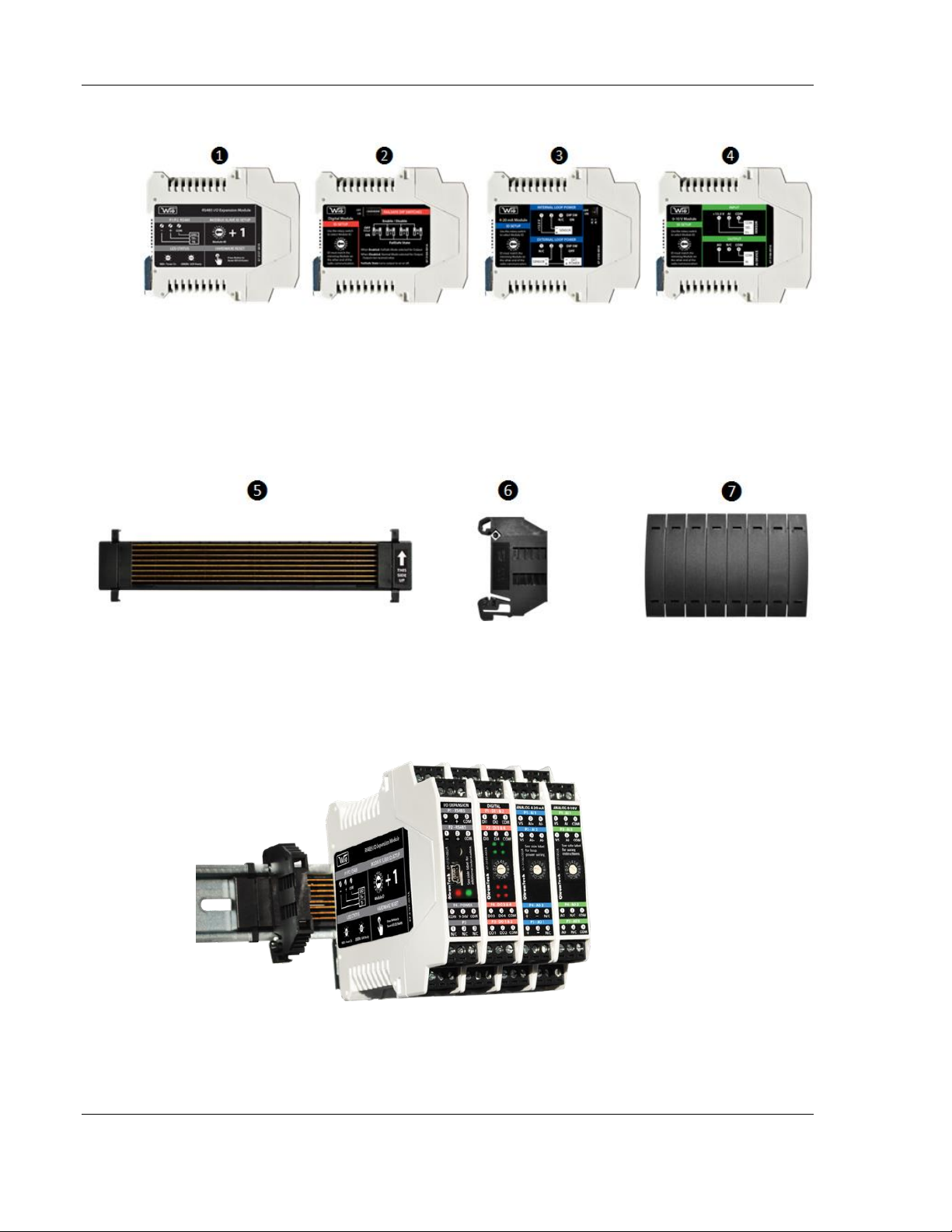
2.2 Hardware
1. RS485 I/O Expansion Module: BM-1000-PM1 (US), BM-0915-RM1 (Int),
BM-2400-RM1 (US), BM-2410-RM1 (Int)
2. Digital Module: BM-D100-144 (US); BM-D100-244 (International)
3. 4-20 mA Analog Module: BM-A420-122 (US); BM-A420-122 (International)
4. 0-10 V Analog Module: BM-A010-122 (US); BM-A010-122 (International)
5. DataRail attaches onto 35 mm x 7.5 mm DIN rail (Standard length included in Radio Kit can
support 1 RS485 I/O Expansion Module + 5 I/O Modules)
6. End Terminal Bracket for securing DataRail and Modules to DIN Rail
7. DataRail Cover for protecting empty DataRail slots
Page 10 of 36 ProSoft Technology, Inc.
June 10, 2015
Page 11
Specifications
HARDWARE & SYSTEM
Unique Features
Works with Any Modbus RS485 Master Device
No Software Configuration Required
Single Point Power Termination
Maximum Network Capacity*
System can support up to sixteen (16) Digital Modules max
System can support up to eight (8) 0-10 V Modules max
System can support up to five (5) 4-20 mA Modules max
When adding more than five (5) I/O Modules and creating different
I/O Module combinations, please determine maximum allowable I/O
Module combination per system by utilizing the power budget
calculator.
Power Budget Calculator
http://psft.com/A7U
Data Encoding Method
MSB First
I/O Module Slave ID Selection
16-Position Rotary Switch (+1 for Modbus Slave ID)
DIN Rail Mounting Compatibility
35 mm x 7.5 mm DIN Rail
DataRail™ (Included w/ Kit)
6.1" / 156 mm - Supports Up to Exp. + 5x I/O Modules
Auto-Detection of Modules
Yes, via DataRail at Power-Up
DataRail Mounting Hardware
4-Claw Attachment to 35 mm DIN Rail with End Terminal Bracket
Built-In Mounting Hardware
Spring-Loaded Clip-On System
Wire Gauge
Solid / Stranded (AWG) 28-12 Gauge
Wire Rating
UL: 300 V RMS, 80 °C and 300 V, 105 °C
CSA: 300 V RMS, 105 °C
Warranty
2-Year Limited
SAFETY & COMPLIANCE
RADIO
Operational Temperature
-40 °C to 85 °C / -40 °F to 185 °F
Ambient Temperature
-20 °C to 85 °C / -4 °F to 185 °F
Humidity
0 to 99 %, Non-condensing
Degree of Protection / Housing Type
IP20 / Plastic
Hazardous Locations Classifications
Class I; Division 2 (Zone 2), Pending
3 Specifications
3.1 Hardware and System
3.2 Safety and Compliance
ProSoft Technology, Inc. Page 11 of 36
June 10, 2015
Page 12
Specifications
RS485 Expansion I/O Module
Baud Rate
9600 bits per second
Data Bits
8
Parity / Stop Bits
None / 1
RS485 Modbus Slave Addressing
Interface Supports up to 16 Addresses / I/O Modules*
Red LED (Left)
Power
Green LED (Right)
USB-Ready (For Firmware Update)
Supply Voltage Range
9 - 30 VDC (± 5 %)
Protection Against Polarity
Yes
Power Consumption
Typical: 20 mA / Max: 24 mA @12 VDC
Packaging Dimensions (WxHxD)
5.5 x 10.1 x 2.8-in / 140 x 257 x 72mm
Net Dimensions (WxHxD)
0.7 x 3.9 x 4.5-in / 17.5 x 99 x 114mm
Packaging Weight
0.8 lbs / 363 g
Net Weight
0.3 lbs / 136 g
Digital I/O Module
Number of Inputs
4
Number of Outputs
4
Isolation Voltage
2500 V r.m.s.
Input Voltage Range
3-30 VDC
Input Voltage Threshold
1 Signal ("H"): > 2.3 VDC
0 Signal ("L"): < 1.1 VDC
Output Rating
1 A Sink Current for Open-Drain Outputs / NPN
Green LEDs
Input Indicators
Red LEDs
Output Indicators
Power Consumption
Typical: 18 mA / Max: 26 mA @12 VDC
Packaging Dimensions
(WxHxD) 4.8 x 5.1 x 2.8-in / 123 x 129 x 72mm
Net Dimensions
0.7 x 3.9 x 4.5-in / 17.5 x 99 x 114mm
Packaging Weight
Single: 0.5 lbs / 227 g; Double: 0.8 lbs / 363 g
Net Weight (Single)
0.3 lbs / 136 g
3.3 RS485 Expansion I/O Module
3.4 Digital I/O Module
Page 12 of 36 ProSoft Technology, Inc.
June 10, 2015
Page 13
Specifications
Analog 4-20 mA I/O Module
Number of Inputs
2 (24-bit Resolution)
Number of Outputs
2 (16-bit Resolution)
Isolation Voltage
2500 V r.m.s.
Signal Range
4 mA to 20 mA
Accuracy
< 0.28 % of Full Scale
Internal Loop Power
+13.5 VDC
AI Input Impedance (loop)
128 Ohm
AO Terminal Voltage Range
10 VDC Min. / 31.5 VDC Max.
Power Consumption
Typical: 50 mA / Max: 75 mA @12 VDC
Packaging Dimensions
(WxHxD) 4.8 x 5.1 x 2.8-in / 123 x 129 x 72mm
Net Dimensions
0.7 x 3.9 x 4.5-in / 17.5 x 99 x 114mm
Packaging Weight
Single: 0.5 lbs / 227 g; Double: 0.8 lbs / 363 g
Net Weight (Single)
0.3 lbs / 136 g
Analog 0-10 V I/O Module
Number of Inputs
2 (24-bit Resolution)
Number of Outputs
2 (16-bit Resolution)
Isolation Voltage
2500 V r.m.s.
Signal Range
0 VDC to 10 VDC (10.5 V Max)
Accuracy
< 0.1 % of Full Scale
AI Input Impedance
40K Ohm
AO Output Impedance
10 Ohm
Power Consumption
Typical: 40 mA / Max: 45 mA @12 VDC
Packaging Dimensions
(WxHxD) 4.8 x 5.1 x 2.8-in / 123 x 129 x 72mm
Net Dimensions
0.7 x 3.9 x 4.5-in / 17.5 x 99 x 114mm
Packaging Weight
Single: 0.5 lbs / 227 g; Double: 0.8 lbs / 363 g
Net Weight (Single)
0.3 lbs / 136 g
ORDERING INFORMATION
RS485
RS485 Expansion Kit
BM-1000-PM1K
Kit Content
RS485 Expansion I/O Module, DataRail,
2x End Terminal Brackets, DataRail Cover,
Quick Start Guide, Technician's Screwdriver
Digital I/O
1-Pack: BM-D100-144S
2-Pack: BM-D100-144D
4-20 mA I/O
1-Pack: BM-A420-122S
2-Pack: BM-A420-122D
0-10 V I/O
1-Pack: BM-A010-122S
2-Pack: BM-A010-122D
3.5 4-20 mA I/O Module
3.6 0-10 V I/O Module
3.7 Ordering Information
ProSoft Technology, Inc. Page 13 of 36
June 10, 2015
Page 14

Specifications
Page 14 of 36 ProSoft Technology, Inc.
June 10, 2015
Page 15

Installation
4 Installation
4.1 Outdoor Enclosure Installation
1. Install or use existing outdoor NEMA-type enclosure.
2. Be sure the RS485 I/O Expansion System meets applicable grounding requirements
in the enclosure.
3. Install a 35 mm x 7.5 mm DIN rail (at least 166 mm (6.5-inch) wide) inside the
enclosure.
4. Provide external power supply: 9-30 VDC.
5. Make a hole on the bottom of the enclosure to run wires.
6. Run conduit for power and I/O cabling.
7. Feed power wiring into enclosure.
8. Terminate RS485 wiring.
ProSoft Technology, Inc. Page 15 of 36
June 10, 2015
Page 16

Installation
4.2 RS485 I/O Expansion System Assembly
Warning: Power must be disconnected or turned off prior to attaching or removing any I/O
Modules from the system – failure to comply may cause damage hardware.
1. Securely attach the DataRail onto a 35 mm x 7.5 mm DIN rail by gently
pressing on all four (4) corner clips.
2. Secure DataRail to DIN rail by attaching an End Terminal Bracket.
a. First, hook the metal end of the Bracket to DIN rail and then snap the
other end onto the DIN rail. (Make sure to position the Bracket on the far
left of the DataRail where metal blades meet the plastic).
Page 16 of 36 ProSoft Technology, Inc.
June 10, 2015
Page 17

Installation
3. Attach RS485 I/O Expansion Module to DataRail (place it next to the Bracket
4. Attach I/O Module(s) to the system.
without any gap).
a. First, latch the top hook onto the rail, then snap-in the spring-loaded clip
into place.
a. Place Modules in any combination (do not leave gaps between Modules).
b. When using more than five (5) I/O Modules, determine maximum I/O
Module combination by using power budget calculator: http://psft.com/A7U
c. Use the 16-position switch located on the front of each I/O Module to set
the Modbus Slave ID(s). Slave ID = Switch position number + 1.
Ex: Switch ID 0 + 1 = Slave ID 1
ProSoft Technology, Inc. Page 17 of 36
June 10, 2015
Page 18

Installation
5. Attach the other End Terminal Bracket to secure the Modules. (Place it next
to the last module without leaving a gap)
6. Protect any unused DataRail slots with the cover. Snap-off extra pieces and
store for future use.
7. Terminate the RS485 terminals.
Page 18 of 36 ProSoft Technology, Inc.
June 10, 2015
Page 19
Installation
8. Terminate I/O and supply power as required. Use solid or stranded wire
(AWG) 28-12.
ProSoft Technology, Inc. Page 19 of 36
June 10, 2015
Page 20
Installation
4.3 RS485 Daisy-Chain Diagram
1. If more I/O Modules are required, another RS485 I/O Expansion Module (Kit) set
can be deployed simply using the daisy-chain method.
2. The System holds up to 16 I/O Module Slave addresses regardless of the number
of RS485 I/O Expansion Modules deployed.
3. Each Module must be set to a unique Modbus Slave address.
Page 20 of 36 ProSoft Technology, Inc.
June 10, 2015
Page 21

Installation
4.4 Detaching Components from the DataRail
Warning: All live wiring connections and power must be safely disconnected before taking any
components off the DataRail or Wireless I/O System!
1. The End Terminal Bracket can be removed from the DIN rail by inserting the
tip of a flathead screwdriver into the removal slot. Control the direction with
the screwdriver handle to pull the latch away from the DIN rail.
2. Wireless I/O Modules can be removed from the DIN rail by inserting the tip of
a flathead screwdriver into removal slot located on the metal clip. Lift-up on
the screwdriver handle to pull the spring-loaded clip away from the DIN rail.
ProSoft Technology, Inc. Page 21 of 36
June 10, 2015
Page 22

Page 23
Wiring Diagrams
Data Encoding Method
(Word Order):
MSB First
Data Encoding Method
(Word Order):
MSB First
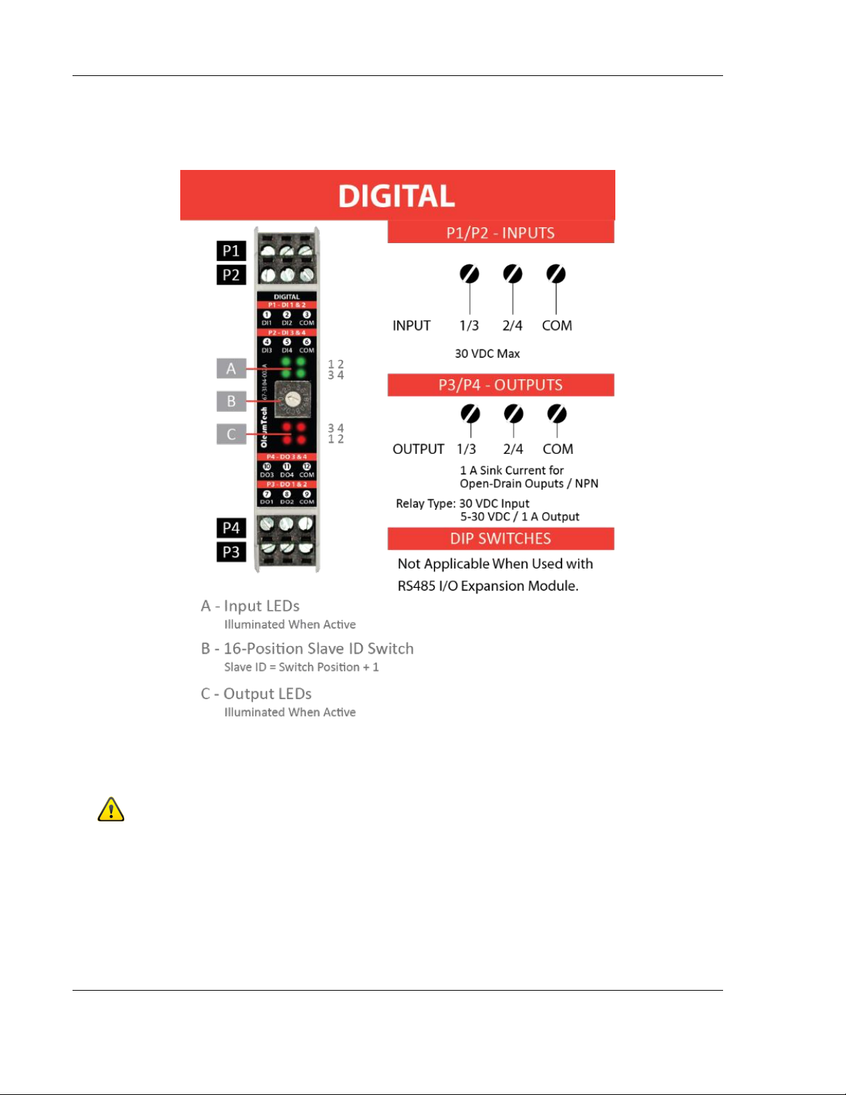
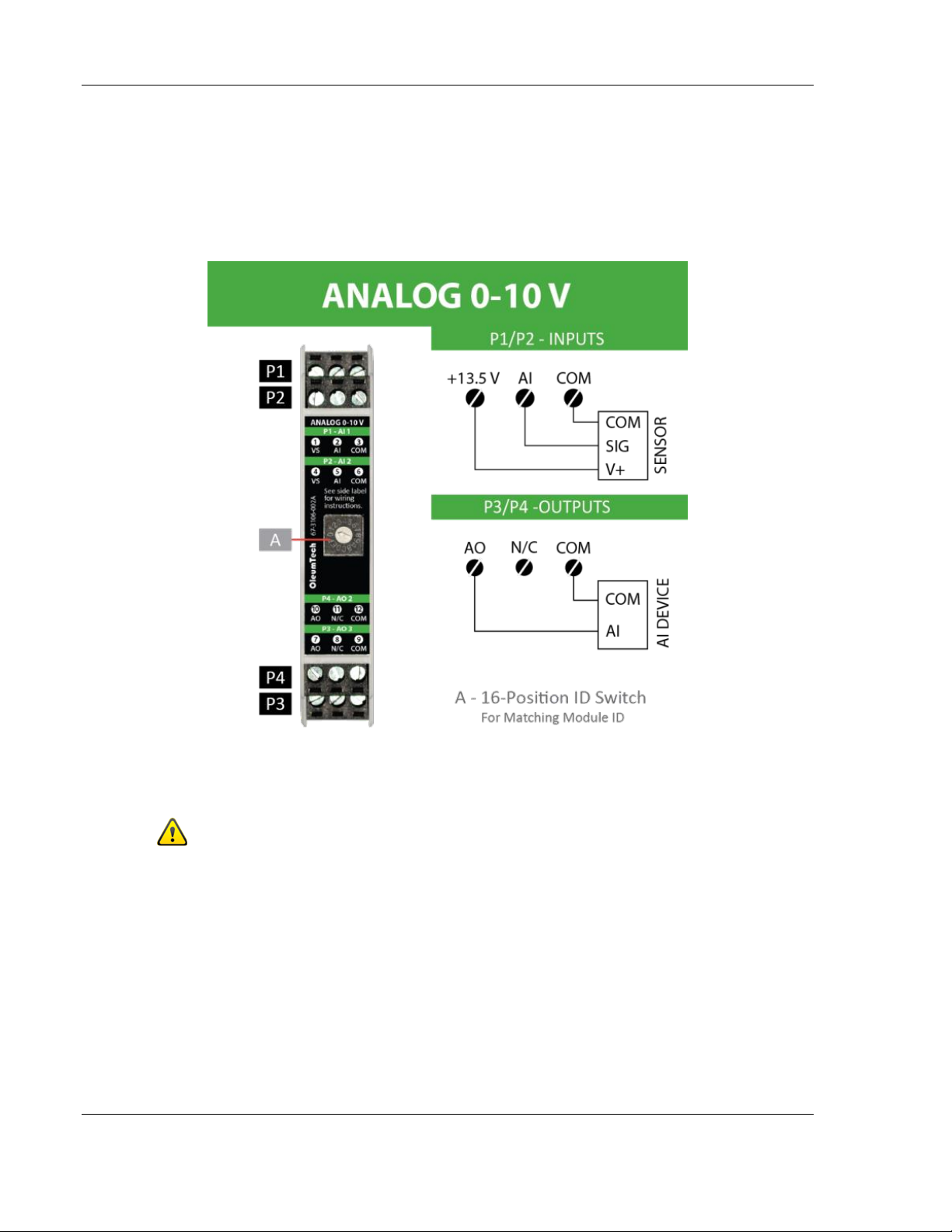
5 Wiring Diagrams
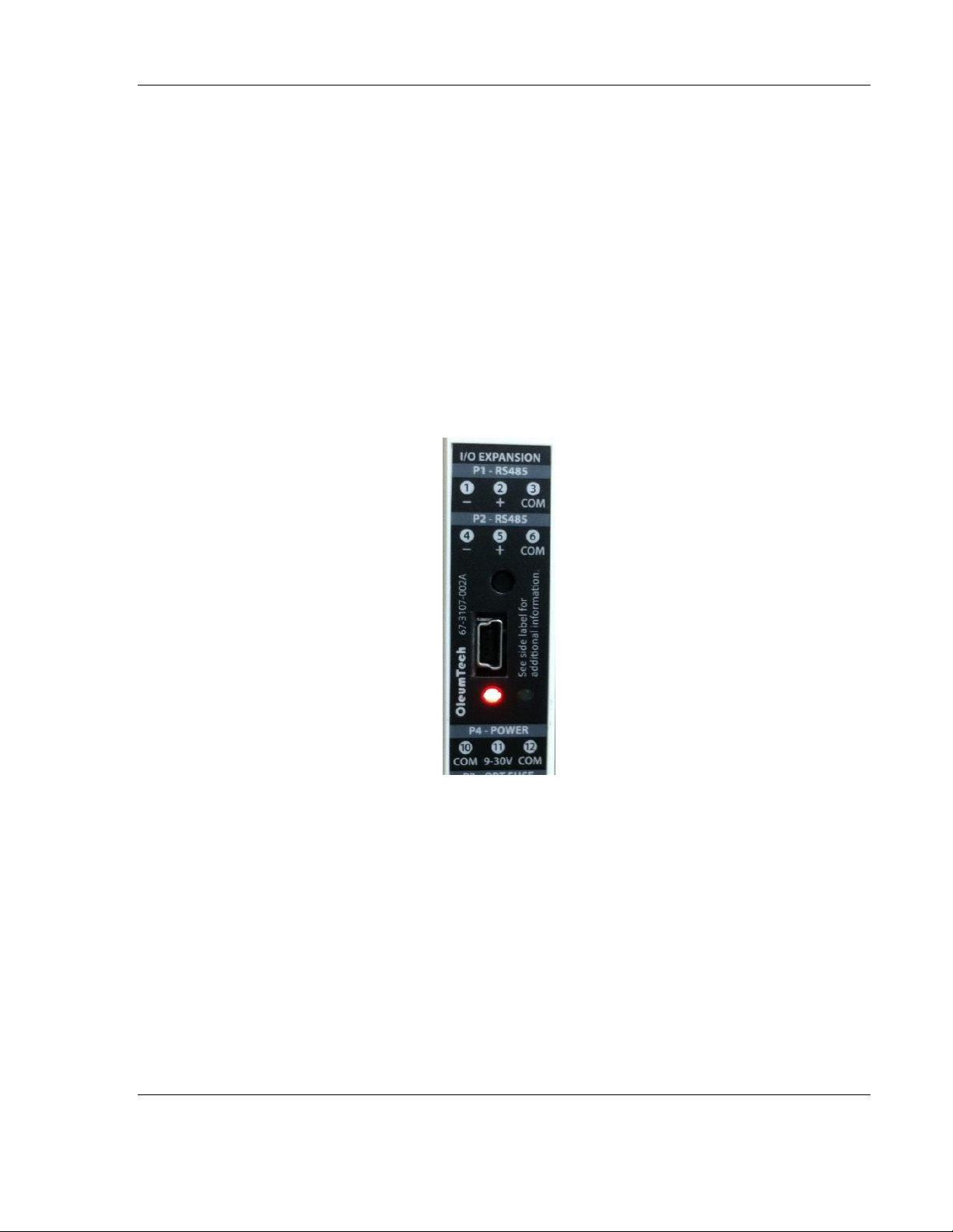
5.1 RS485 I/O Expansion Module
(BM-1000-PM1 Shown)
ProSoft Technology, Inc. Page 23 of 36
June 10, 2015
Use Solid / Stranded (AWG) 28-12 Wire Gauge
RS485 I/O Expansion Module does not share a common ground with I/O
Modules. All inputs and outputs on I/O Modules provide field isolation.
Page 24
Wiring Diagrams
5.2 Digital Module
(BM-D100-144 Shown)
Use Solid / Stranded (AWG) 28-12 Wire Gauge
Digital I/O Module does not share a common ground with RS485 Module. All inputs and
outputs on I/O Modules provide field isolation.
If input sensor is powered from the same source as RS485 Module, be sure to
establish a common ground, otherwise sensor will not work properly.
Page 24 of 36 ProSoft Technology, Inc.
June 10, 2015
Page 25
Wiring Diagrams
5.3 Analog 4-20 mA Module
(BM-A420-122 Shown)
VS/External Power (min) = 10 + Max Current (Amp) * R
R
4-20 mA I/O Module does not share a common ground with RS485 Module.
All inputs and outputs on I/O Modules provide field isolation.
= Total Loop Impedance
loop
Use Solid / Stranded (AWG) 28-12 Wire Gauge
loop
ProSoft Technology, Inc. Page 25 of 36
June 10, 2015
Page 26
Wiring Diagrams
5.4 Analog 0-10 V Module
(BM-A010-122 Shown)
Use Solid / Stranded (AWG) 28-12 Wire Gauge
0-10 V I/O Module does not share a common ground with RS485 Module.
All inputs and outputs on I/O Modules provide field isolation.
Page 26 of 36 ProSoft Technology, Inc.
June 10, 2015
Page 27

Modbus Mapping
Digital
Digital, 4-20mA, 0-10 V
Digital, 4-20mA, 0-10 V
Digital
0x10
0x0F
Write Single Coil
Write Single Register
Write Multiple Registers
Write Multiple Coils
0x06
Definitions
Applicable Module(s)
Digital
Digital
Digital, 4-20mA, 0-10 V
Read Coils
Read Discrete Inputs
Read Holding Registers
0x01
0x02
0x03
0x05
Supported Function Codes
6 Modbus Mapping
6.1 Supported Modbus Function Codes
6.2 Digital I/O Module – Modbus Mapping Table
ProSoft Technology, Inc. Page 27 of 36
June 10, 2015
Page 28
Modbus Mapping
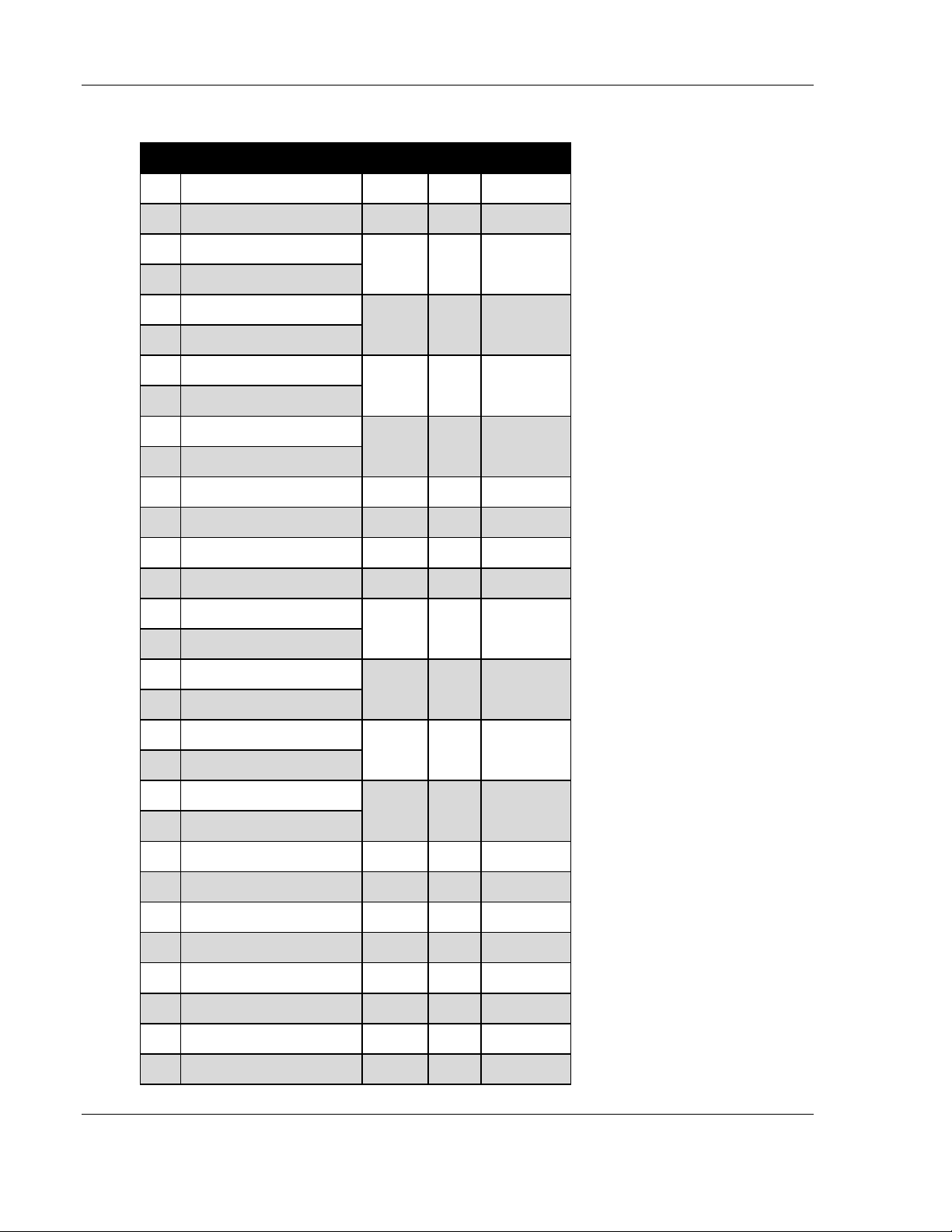
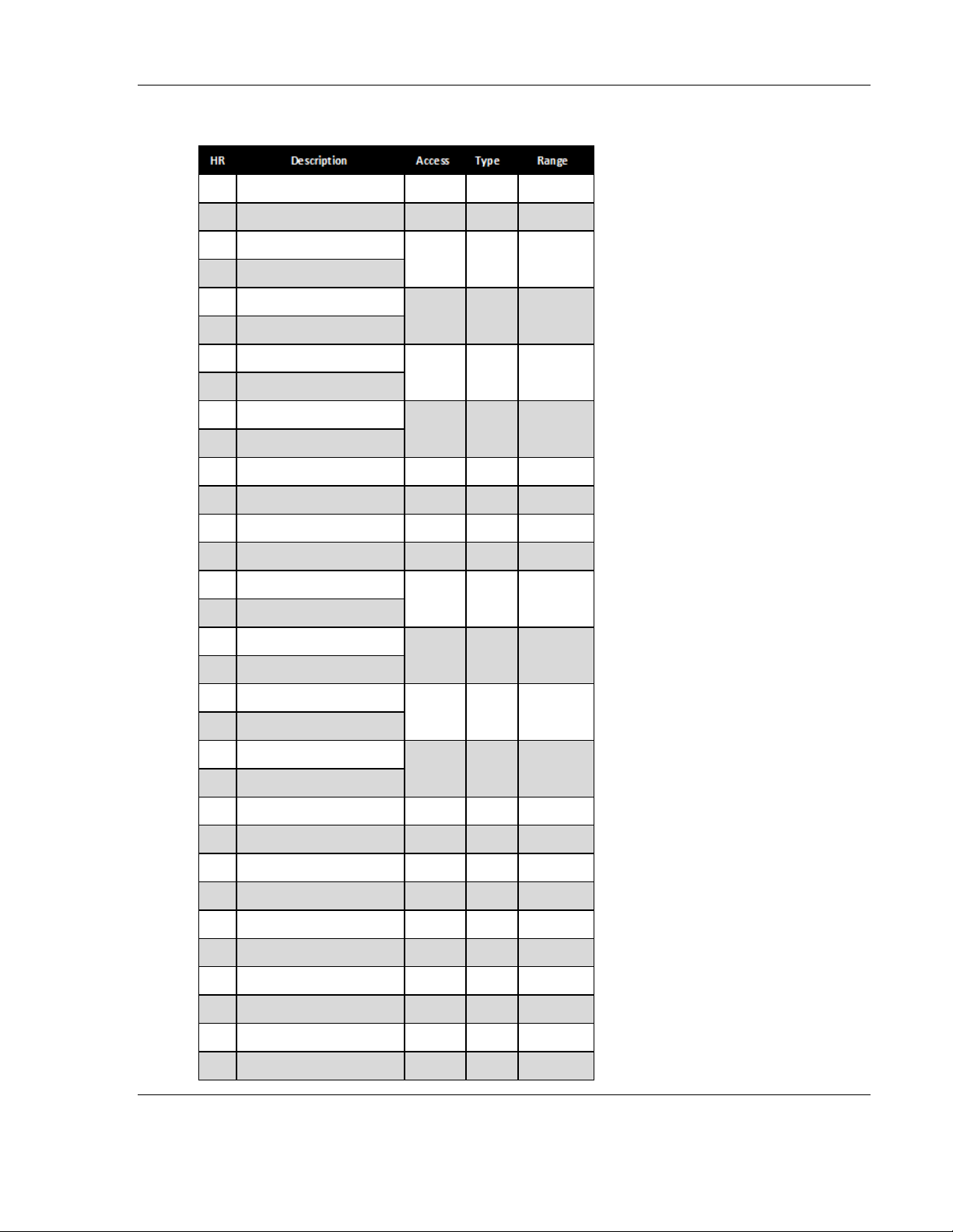
HR Description Access Type Range
3001 Analog Input 1 Current /1 000 Read UINT 16 4000..20,000
3002 Analog Input 2 Current /1 000 Read UINT 16 4000..20,000
3003 Analog Input 1 Raw Split-Hi
3004 Analog Input 1 Raw Split-Lo
3005 Analog Input 2 Raw Split-Hi
3006 Analog Input 2 Raw Split-Lo
3007 Analog Input 1 Current Split-Hi
3008 Analog Input 1 Current Split-Lo
3009 Analog Input 2 Current Split-Hi
3010 Analog Input 2 Current Split-Lo
3011 Analog Output 1 Current /1 000 Read/Write UINT 16 0..20,000
3012 Analog Output 2 Current /1 000 Read/Write UINT 16 0..20,000
3013 Analog Output 1 % /100 Read/Write UINT 16 0..10,000
3014 Analog Output 2 % /100 Read/Write UINT 16 0..10,000
3015 Analog Output 1 Current Split-Hi
3016 Analog Output 1 Current Split-Lo
3017 Analog Output 2 Current Split-Hi
3018 Analog Output 2 Current Split-Lo
3019 Analog Output 1 % Split-Hi
3020 Analog Output 1 % Split-Lo
3021 Analog Output 2 % Split-Hi
3022 Analog Output 2 % Split-Lo
5001 Analog Input 1 Raw Read UINT 32 0..8,388,607
5002 Analog Input 2 Raw Read UINT 32 0..8,388,607
7001 Analog Input 1 Current Read IEE FLOAT 4 .0..20.0
7002 Analog Input 2 Current Read IEE FLOAT 4 .0..20.0
7003 Analog Output 1 Current Read/Write IEE FLOAT 4.0..20.0
7004 Analog Output 2 Current Read/Write IEE FLOAT 4.0..20.0
7005 Analog Output 1 % Read/Write IEE FLOAT 0.0..100.0
7006 Analog Output 2 % Read/Write IEE FLOAT 0.0..100.0
Read/Write
UINT 32
0..8,388,607
UINT 32
0..8,388,607
Read
Read
IEE FLOAT
0.0..100.0
IEE FLOAT
0.0..100.0
IEE FLOAT
4.0..20.0
IEE FLOAT
4.0..20.0
IEE FLOAT
4.0..20.0
IEE FLOAT
4.0..20.0
Read
Read
Read/Write
Read/Write
Read/Write
6.3 4-20 mA I/O Module - Modbus Mapping Table
Page 28 of 36 ProSoft Technology, Inc.
June 10, 2015
Page 29
Modbus Mapping
3001 Analog Input 1 Volts /1000 Read UINT 16 0..10,000
3002 Analog Input 2 Volts /1000 Read UINT 16 0..10,000
3003 Analog Input 1 Raw Split-Hi
3004 Analog Input 1 Raw Split-Lo
3005 Analog Input 2 Raw Split-Hi
3006 Analog Input 2 Raw Split-Lo
3007 Analog Input 1 Volts Split-Hi
3008 Analog Input 1 Volts Split-Lo
3009 Analog Input 2 Volts Split-Hi
3010 Analog Input 2 Volts Split-Lo
3011 Analog Output 1 Raw Read/Write UINT 16 0..65,535
3012 Analog Output 2 Raw Read/Write UINT 16 0..65,535
3013 Analog Output 1 Volts / 1000, % /100 Read/Write UINT 16 0..10,000
3014 Analog Output 2 Volts /1000, % / 100 Read/Write UINT 16 0..10,000
3015 Analog Output 1 V olts Split-Hi
3016 Analog Output 1 Volts S plit-Lo
3017 Analog Output 2 V olts Split-Hi
3018 Analog Output 2 Volts S plit-Lo
3019 Analog Output 1 % Split-Hi
3020 Analog Output 1 % Split-Lo
3021 Analog Output 2 % Split-Hi
3022 Analog Output 2 % Split-Lo
5001 Analog Input 1 Raw Read UINT 32 0..8,388,607
5002 Analog Input 2 Raw Read UINT 32 0..8,388,607
7001 Analog Input 1 Volts Read IEE FLOAT 0.0..10.0
7002 Analog Input 2 Volts Read IEE FLOAT 0.0..10.0
7003 Analog Output 1 Raw Read/Write IEE FLOAT 0.0..65,535.0
7004 Analog Output 2 Raw Read/Write IEE FLOAT 0.0..65,535.0
7005 Analog Output 1 Volts Read/Write IEE FLOAT 0.0..10.0
7006 Analog Output 2 Volts Read/Write IEE FLOAT 0.0..10.0
7007 Analog Output 1 % Read/Write IEE FLOAT 0.0..100.0
7008 Analog Output 2 % Read/Write IEE FLOAT 0.0..100.0
0..8,388,607
UINT 32
0..8,388,607
UINT 32
Read
Read
IEE FLOAT
0.0..10.0
IEE FLOAT
0.0..100.0
IEE FLOAT
0.0..100.0
IEE FLOAT
0.0..10.0
IEE FLOAT
0.0..10.0
IEE FLOAT
0.0..10.0
Read/Write
Read
Read
Read/Write
Read/Write
Read/Write
6.4 0-10 V I/O Module - Modbus Mapping Table
ProSoft Technology, Inc. Page 29 of 36
June 10, 2015
Page 30

Page 30 of 36 ProSoft Technology, Inc.
June 10, 2015
Page 31
Diagnostics
7 Diagnostics
7.1 Radio Module
1. Power LED (Left)
a. Red: Power on
b. LED not on: No power
i. Verify power supply wiring and polarity. (+ to 9-30V, - to COM)
ii. Verify correct pin outs are used. (pin 11 for +, pin 10 or 12 for - )
iii. Verify 9-30 VDC is supplied to the unit.
ProSoft Technology, Inc. Page 31 of 36
June 10, 2015
Page 32

Diagnostics
2. I/O LED (Right):
a. Green: USB enabled
b. LED not on: No power
i. Connect USB to PC first, then to I/O Expansion Module.
ii. Verify unit is powered on, Power LED (left) should be red.
iii. Verify the PC is on.
3. Unable to Read/Write Modbus Values
a. Verify that the Modbus slave ID is the Module ID + 1
Example: If the Module ID is 0, the Modbus slave ID will be 1
b. Select MSB first when applicable when setting up Modbus Master device.
c. Verify Modbus RS485 wiring (3-wire).
d. Verify baud rate, data bits, parity, and stop bits (9600 / 8 / None / 1).
e. Refer to Modbus Mapping (page 27).
i. Verify the Modbus function code.
ii. Verify the Modbus register address.
iii. Verify the data type (integer/float, 16/32 bit).
iv. Verify if address has read/write or only read function capabilities.
Page 32 of 36 ProSoft Technology, Inc.
June 10, 2015
Page 33

Frequently Asked Questions
8 Frequently Asked Questions
1. What is the RS485 I/O Expansion System designed for?
a. It is designed to easily and economically add local I/O points to any industrial
monitoring or control system via RS485 Modbus connectivity.
2. What type of I/O’s are available?
a. Digital/discrete
b. Analog 4-20 mA
c. Analog 0-10 V
3. Does this System require software configuration?
a. No, it requires absolutely no software.
b. Slave ID switch on each I/O Module is used to set the Slave ID.
c. The RS485 I/O Expansion Modules provides power and controls the I/O images.
4. How many I/O Modules can I connect to one RS485 expansion I/O system?
a. Digital: up to 16
b. 4-20 mA: up to 5
c. 0-10 V: up to 8
d. When mixing Modules, use Power Budget Calculator to determine max number
of Modules per system: http://psft.com/A7U
5. Can I use the same I/O Modules with the WIO® Wireless System for replicating
hardwire?
a. Yes, the WIO I/O Modules can be used for both wireless and RS485 I/O
applications
6. Do the I/O Modules require a firmware change when changing from RS485 to
wireless application?
a. No, the I/O Modules are designed to work with either the WIO® Radios or RS485
I/O Expansion Module.
7. How many I/O modules can be connected with the standard DataRail (6.1”) shipped
with RS485 Kit?
a. Standard DataRail supports up to five (5) I/O modules in addition to one RS485
Module.
8. What is the mini USB port on the RS485 Module used for?
a. For updating device firmware via PC.
9. Can the RS485 I/O Expansion System be used in hazardous locations?
a. Yes, the system can be used in Class 1, Division 2 or Zone 2 locations.
Certification pending.
10. How can I obtain tech support or RMA?
a. Please email us at support@prosoft-technology.com or give us a call to begin the
service process. You will be guided by our helpful customer service staff member
to help you get through any issue you are having with the Wireless I/O System.
ProSoft Technology, Inc. Page 33 of 36
June 10, 2015
Page 34

Page 34 of 36 ProSoft Technology, Inc.
June 10, 2015
Page 35

Support, Service & Warranty
9 Support, Service & Warranty
ProSoft Technology, Inc. (ProSoft) is committed to providing the most efficient
and effective support possible. Before calling, please gather the following
information to assist in expediting this process:
1 Product Version Number
2 System architecture
3 Network details
If the issue is hardware related, we will also need information regarding:
1 Module configuration and associated ladder files, if any
2 Module operation and any unusual behavior
3 Configuration/Debug status information
4 LED patterns
5 Details about the serial, Ethernet or fieldbus devices interfaced to the module,
if any.
Note: For technical support calls within the United States, an after-hours answering system allows
24-hour/7-days-a-week pager access to one of our qualified Technical and/or Application Support
Engineers. Detailed contact information for all our worldwide locations is available on the following
page.
ProSoft Technology, Inc. Page 35 of 36
June 10, 2015
Page 36

Support, Service & Warranty
Internet
Web Site: www.prosoft-technology.com/support
E-mail address: support@prosoft-technology.com
Asia Pacific
(location in Malaysia)
Tel: +603.7724.2080, E-mail: asiapc@prosoft-technology.com
Languages spoken include: Chinese, English
Asia Pacific
(location in China)
Tel: +86.21.5187.7337 x888, E-mail: asiapc@prosoft-technology.com
Languages spoken include: Chinese, English
Europe
(location in Toulouse, France)
Tel: +33 (0) 5.34.36.87.20,
E-mail: support.EMEA@prosoft-technology.com
Languages spoken include: French, English
Europe
(location in Dubai, UAE)
Tel: +971 (0)4.214.6911,
E-mail: mea@prosoft-technology.com
Languages spoken include: English, Hindi
North America
(location in California)
Tel: +1 661-716-5100,
E-mail: support@prosoft-technology.com
Languages spoken include: English, Spanish
Latin America
(Oficina Regional)
Tel: +1-281-298-9109,
E-Mail: latinam@prosoft-technology.com
Languages spoken include: Spanish, English
Latin America
(location in Puebla, Mexico)
Tel: +52-222-399-6565,
E-mail: soporte@prosoft-technology.com
Languages spoken include: Spanish
Brasil
(location in Sao Paulo)
Tel: +55-11-5083-3776,
E-mail: brasil@prosoft-technology.com
Languages spoken include: Portuguese, English
9.1 Warranty Information
For complete details regarding ProSoft Technology’s TERMS & CONDITIONS
OF SALE, WARRANTY, SUPPORT, SERVICE AND RETURN MATERIAL
AUTHORIZATION INSTRUCTIONS please see the documents on the Product
DVD or at www.prosoft-technology.com/warranty.
All documentation is subject to change without notice.
Page 36 of 36 ProSoft Technology, Inc.
June 10, 2015
 Loading...