

Page 1

RIO
ProLinx Gateway
®
Rockwell Automation
Adapter
Remote I/O
February 04, 2010
DRIVER MANUAL
Page 2

Important Installation Instructions
Power, Input, and Output (I/O) wiring must be in accordance with Class I, Division 2 wiring methods, Article 501-4 (b)
of the National Electrical Code, NFPA 70 for installation in the U.S., or as specified in Section 18-1J2 of the Canadian
Electrical Code for installations in Canada, and in accordance with the authority having jurisdiction. The following
warnings must be heeded:
A WARNING - EXPLOSION HAZARD - SUBSTITUTION OF COMPONENTS MAY IMPAIR SUITABILITY FOR
CLASS I, DIV. 2;
B WARNING - EXPLOSION HAZARD - WHEN IN HAZARDOUS LOCATIONS, TURN OFF POWER BEFORE
REPLACING OR WIRING MODULES
C WARNING - EXPLOSION HAZARD - DO NOT DISCONNECT EQUIPMENT UNLESS POWER HAS BEEN
SWITCHED OFF OR THE AREA IS KNOWN TO BE NONHAZARDOUS.
D THIS DEVICE SHALL BE POWERED BY CLASS 2 OUTPUTS ONLY.
All ProLinx® Products
WARNING – EXPLOSION HAZARD – DO NOT DISCONNECT EQUIPMENT UNLESS POWER HAS BEEN
SWITCHED OFF OR THE AREA IS KNOWN TO BE NON-HAZARDOUS.
AVERTISSEMENT – RISQUE D'EXPLOSION – AVANT DE DÉCONNECTER L'EQUIPMENT, COUPER LE
COURANT OU S'ASSURER QUE L'EMPLACEMENT EST DÉSIGNÉ NON DANGEREUX.
Markings
UL/cUL ISA 12.12.01 Class I, Div 2 Groups A, B, C, D
cUL C22.2 No. 213-M1987
243333 183151
CL I Div 2 GPs A, B, C, D
Temp Code T5
II 3 G
Ex nA nL IIC T5 X
0° C <= Ta <= 60° C
II – Equipment intended for above ground use (not for use in mines).
3 – Category 3 equipment, investigated for normal operation only.
G – Equipment protected against explosive gasses.
ProLinx Gateways with Ethernet Ports
Series C ProLinx™ Gateways with Ethernet ports do NOT include the HTML Web Server. The HTML Web Server
must be ordered as an option. This option requires a factory-installed hardware addition. The HTML Web Server now
supports:
8 MB file storage for HTML files and associated graphics files (previously limited to 384K)
32K maximum HTML page size (previously limited to 16K)
To upgrade a previously purchased Series C model:
Contact your ProSoft Technology distributor to order the upgrade and obtain a Returned Mercha ndise Authorization
(RMA) to return the unit to ProSoft Technology.
To Order a ProLinx Plus gateway with the -WEB option:
Add -WEB to the standard ProLinx part number. For example, 5201-MNET-MCM-WEB.
Page 3

Your Feedback Please
We always want you to feel that you made the right decision to use our products. If you have suggestions, comments,
compliments or complaints about the product, documentation, or support, please write or call us.
ProSoft Technology
5201 Truxtun Ave., 3rd Floor
Bakersfield, CA 93309
+1 (661) 716-5100
+1 (661) 716-5101 (Fax)
www.prosoft-technology.com
support@prosoft-technology.com
Copyright © 2010 ProSoft Technology, Inc., all rights reserved.
RIO Driver Manual
February 04, 2010
ProSoft Technology
Technology, Inc. All other brand or product names are or may be trademarks of, and are used to identify products
and services of, their respective owners.
®
, ProLinx ®, inRAx ®, ProTalk®, and RadioLinx ® are Registered Trademarks of ProSoft
ProSoft Technology® Product Documentation
In an effort to conserve paper, ProSoft Technology no longer includes printed manuals with our product shipments.
User Manuals, Datasheets, Sample Ladder Files, and Configuration Files are provide d on the enclosed CD-ROM,
and are available at no charge from our web site: www.prosoft-technology.com
Printed documentation is available for purchase. Contact ProSoft Technology for pricing and availability.
North America: +1.661.716.5100
Asia Pacific: +603.7724.2080
Europe, Middle East, Africa: +33 (0) 5.3436.87.20
Latin America: +1.281.298.9109
Page 4

Page 5

Contents RIO ♦ ProLinx Gateway
Driver Manual Rockwell Automation® Remote I/O Adapter
Contents
Important Installation Instructions: MVI and ProLinx products ...........................................................2
Your Feedback Please........................................................................................................................3
ProSoft Technology® Product Documentation....................................................................................3
1 Protocol Functional Overview 7
1.1 Remote I/O Port ........................................................................................................7
1.2 Module Internal Database.........................................................................................7
2 Protocol Functional Specifications 11
2.1 Remote I/O Specifications.......................................................................................11
3 RIO Protocol Configuration 13
3.1 Install ProSoft Configuration Builder Software........................................................13
3.2 [RIO]........................................................................................................................18
3.3 Remote I/O Adapter Cable Connection...................................................................20
4 LED Indicators 21
4.1 Remote I/O Interface...............................................................................................21
5 Remote I/O Adapter Status and Error Data 23
5.1 Remote I/O Adapter Error Codes............................................................................24
6 Ladder Programming for RIO Module 25
6.1 Initial Setup..............................................................................................................25
6.2 Input and Output Data Images................................................................................26
6.3 Ladder Logic Programming.....................................................................................27
7 Support, Service & Warranty 31
7.1 How to Contact Us: Technical Support...................................................................31
7.2 Return Material Authorization (RMA) Policies and Conditions................................32
7.3 LIMITED WARRANTY.............................................................................................34
Index 39
ProSoft Technology, Inc. Page 5 of 39
February 4, 2010
Page 6

RIO ♦ ProLinx Gateway Contents
Rockwell Automation® Remote I/O Adapter Driver Manual
Page 6 of 39 ProSoft Technology, Inc.
February 4, 2010
Page 7
Protocol Functional Overview RIO ♦ ProLinx Gateway
Driver Manual Rockwell Automation® Remote I/O Adapter
1 Protocol Functional Overview
In This Chapter
Remote I/O Port ......................................................................................7
Module Internal Database .......................................................................7
The ProLinx Remote I/O (RIO) Adapter communication interface can be used to
interface Rockwell Automation Remote I/O Scanners (PLC, SLC, ControlLogix)
to other communication networks. The RIO interface, as the other solutions in the
ProLinx family, interface to the other communication networks via the module's
internal data table.
1.1 Remote I/O Port
Blue Shield Clear
Blue Shield Clear
12
12
The RIO interface is an adapter (slave) and is connected to a scanner (master)
that controls the data transfer.
For example, the master/slave relationship can be accomplished using the 460XRIO-XXX module (adapter/slave unit) with the Rockwell Automation PLC5
(scanner/master unit). Ladder logic must be programmed into a PLC to perform
BTR/BTW commands to receive and transmit data between the module and the
PLC. The module also supports limited high speed data transfer via the Input and
Output images.
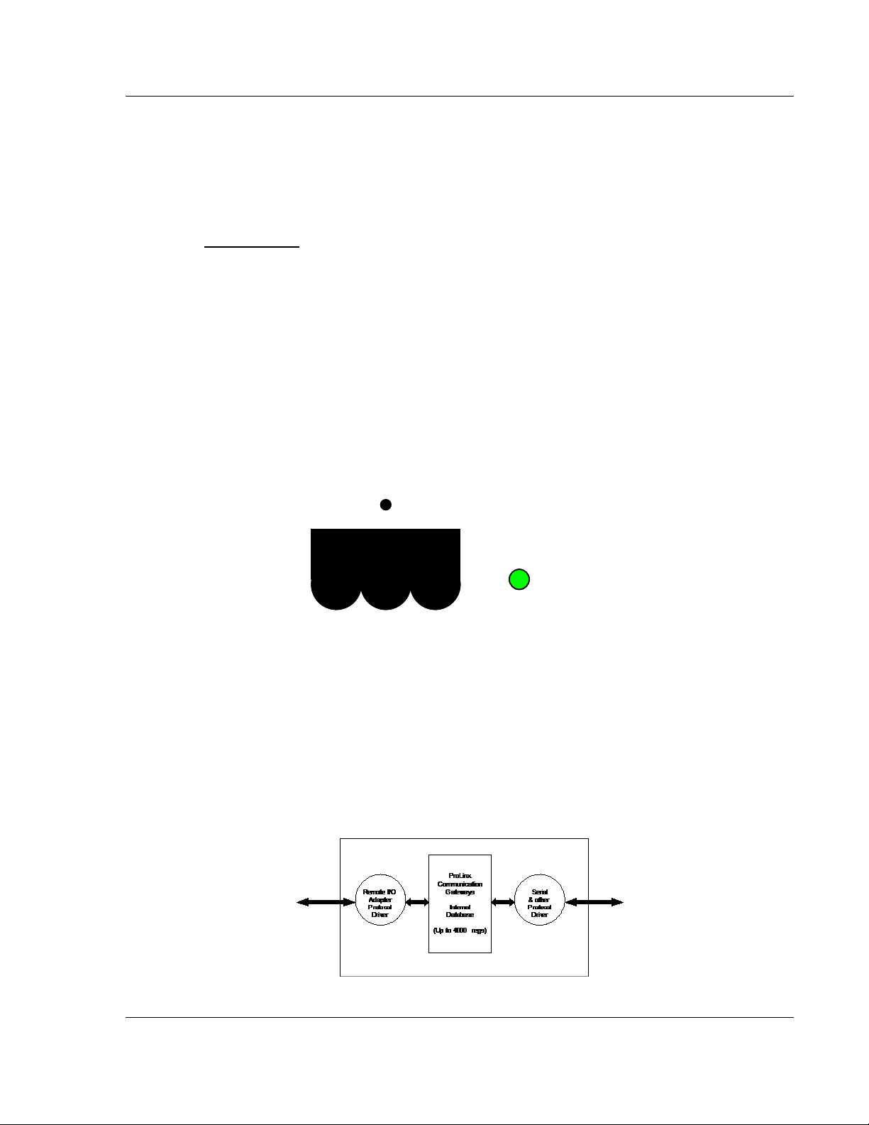
1.2 Module Internal Database
ACTIVE
ACTIVE
ProSoft Technology, Inc. Page 7 of 39
February 4, 2010
Page 8
RIO ♦ ProLinx Gateway Protocol Functional Overview
Rockwell Automation® Remote I/O Adapter Driver Manual
The internal database is central to the functionality of the module. This database
is shared between all the ports on the module and is used as a conduit to pass
information from one device on one network to one or more devices on another
network. This permits data from devices on one communication port to be viewed
and controlled by devices on another port.
In addition to data from the slave and master ports, status and error information
generated by the module can also be mapped into the internal database.
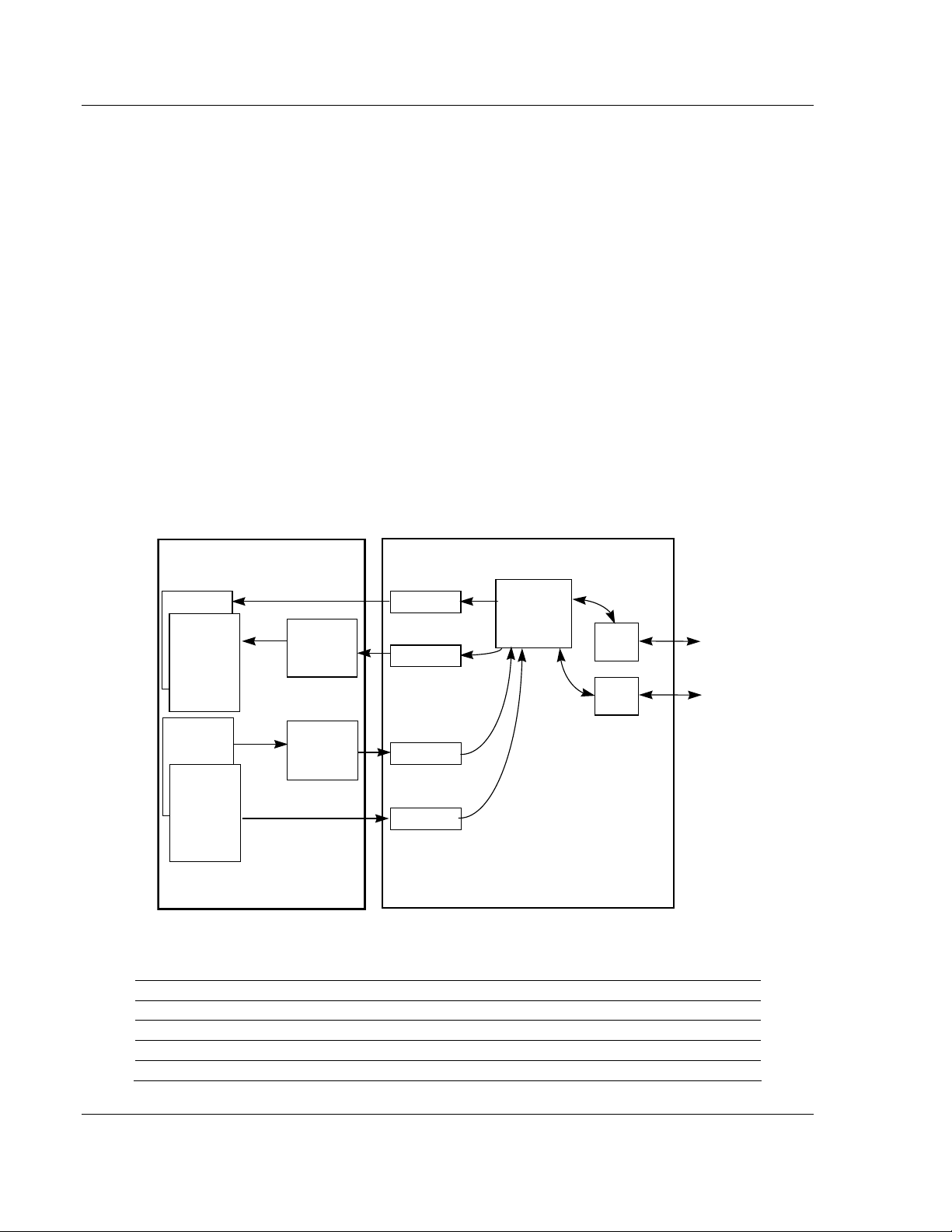
1.2.1 Remote I/O Access to Database
This same internal database is used by the RIO interface to pass information
between the module and the RIO scanner.
A RIO scanner attached to the module can request data from the module’s
database using BTR commands. BTW commands transfer data from the RIO
scanning device to the module’s database. Each data-block is capable of
transferring up to 60-words of data in each block. The module sequentially steps
through the list of read and write blocks configured in the module to transfer the
data between the module and the RIO scanner. The following illustration shows
these relationships:
4601-RIO-MCM Module
Module’s
Internal
Database
Master
Driver
Logic
Slave
Driver
Logic
To Modbus
Slave
Devices
To Modbus
Master
Device
Input Image
Read Data
Write Data
Output Image
Processor
Ladder logic
transfers
data from
module using
BTR commands
Ladder logic
transfers
data to
module using
BTW commands
Input Image
BTR Blocks
RIO Interface
BTW Blocks
Output image
In addition to the block transfer operations, the module reports high-speed data to the RIO scanner
through the input and output image table. The size of this table depends on the rack size selected.
The following table defines the input/output word count for the different rack size selections:
Rack Size Input Word Count Output Word Count
1/4 Rack 1 1
1/2 Rack 3 3
3/4 Rack 5 5
Full Rack 7 7
Page 8 of 39 ProSoft Technology, Inc.
February 4, 2010
Page 9
Protocol Functional Overview RIO ♦ ProLinx Gateway
Driver Manual Rockwell Automation® Remote I/O Adapter
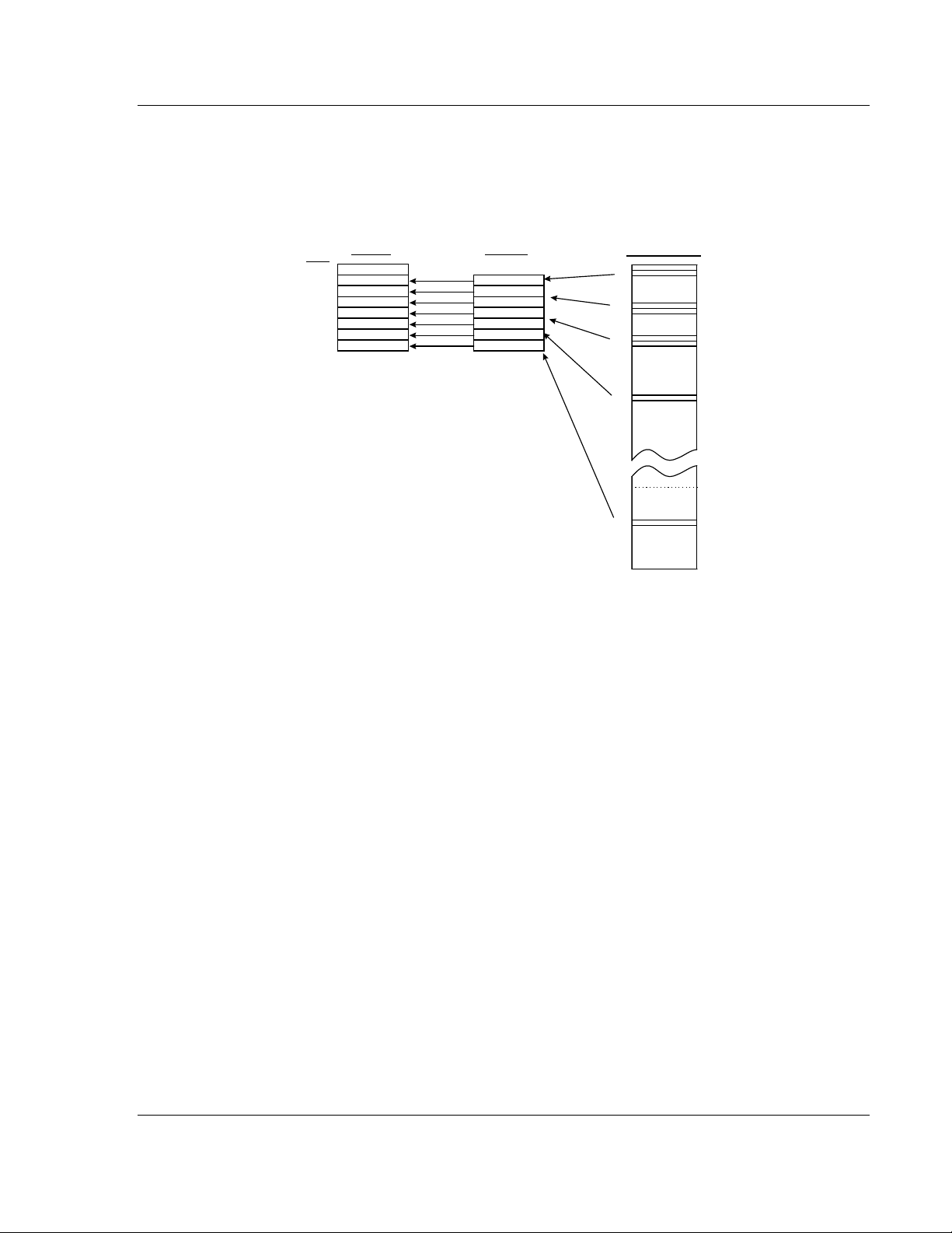
The source for the input word(s) and the destination of the output word(s) in the
internal database is user configured via the CFG file (See [RIO] section in this
manual). Each word is associated with an independent register in the database.
The following illustration shows the relationship between the internal database,
the input map and processor input image:
Input File
Word
0
1
2
3
4
5
6
7
The Input Map acts as a data routing table,
allowing the user to configure the source of data
for the Input Image transferred to the RIO scanner
processor on a high-p ri o r i ty basis.
Input Map
1
100
101
200
201
405
4141
Module Database
0
1
100
101
200
201
405
4141
The same relationship exists for the output image except the data is transferred
from the PLC to the module’s database.
ProSoft Technology, Inc. Page 9 of 39
February 4, 2010
Page 10

RIO ♦ ProLinx Gateway Protocol Functional Overview
Rockwell Automation® Remote I/O Adapter Driver Manual
Page 10 of 39 ProSoft Technology, Inc.
February 4, 2010
Page 11

Protocol Functional Specifications RIO ♦ ProLinx Gateway
Driver Manual Rockwell Automation® Remote I/O Adapter
2 Protocol Functional Specifications
2.1 Remote I/O Specifications
Type Specifications
Software Configurable Parameters
Rack Number Addressing 0 to 63
Rack Size ¼-rack, ½-rack, ¾-rack and full rack
Starting Group 0,2,4,6
Last Rack Yes or No
Baud Rate 57.6K, 115K, 230K
Functional Specifications
Physical Connection
Remote I/O connector
Supports block-transfers of data with scanner
Supports I/O data movement. Amount determined by
rack size configuration
BTW Command: 62 words
BTR Command: 63 words
Standard 3-screw termination connector. Terminal
orientation to allow cable to exit top of connector
ProSoft Technology, Inc. Page 11 of 39
February 4, 2010
Page 12

RIO ♦ ProLinx Gateway Protocol Functional Specifications
Rockwell Automation® Remote I/O Adapter Driver Manual
Page 12 of 39 ProSoft Technology, Inc.
February 4, 2010
Page 13

RIO Protocol Configuration RIO ♦ ProLinx Gateway Driver Manual Rockwell Automation® Remote I/O Adapter
3 RIO Protocol Configuration
In This Chapter
Install ProSoft Configuration Builder Software.......................................13
[RIO]......................................................................................................18
Remote I/O Adapter Cable Connection.................................................20
3.1 Install ProSoft Configuration Builder Software
You must install the ProSoft Configuration Builder (PCB) software to configure
the module. You can always get the newest version of ProSoft Configuration
Builder from the ProSoft Technology web site.
To install ProSoft Configuration Builder from the ProSoft Web Site
1 Open your web browser and navigate to
http://www.prosoft-technology.com/pcb
2 Click the D
Configuration Builder.
3 Choose "S
4 Save the file to your Windows Desktop, so that you can find it easily when
you have finished downloading.
5 When the download is complete, locate and open the file, and then follow the
instructions on your screen to install the program.
If you do not have access to the Internet, you can install ProSoft Configuration
Builder from the ProSoft Solutions CD-ROM, included in the package with your
module.
To install ProSoft Configuration Builder from the Product CD-ROM
1 Insert the ProSoft Solutions Product CD-ROM into the CD-ROM drive of your
PC. Wait for the startup screen to appear.
2 On the startup screen, click P
Windows Explorer file tree window.
3 Click to open the U
and files you will need to set up and configure your module.
4 Double-click the S
"PCB_*.
software on your PC. The information represented by the "*" character in the
file name is the PCB version number and, therefore, subject to change as
new versions of PCB are released.
OWNLOAD HERE link to download the latest version of ProSoft
AVE" or "SAVE FILE" when prompted.
RODUCT DOCUMENTATION. This action opens a
TILITIES folder. This folder contains all of the applications
ETUPCONFIGURATIONTOOL folder, double-click the
EXE" file and follow the instructions on your screen to install the
Note: Many of the configuration and maintenance procedures use files and other utilities on the
CD-ROM. You may wish to copy the files from the Utilities folder on the CD-ROM to a convenient
location on your hard drive.
ProSoft Technology, Inc. Page 13 of 39
February 4, 2010
Page 14

RIO ♦ ProLinx Gateway RIO Protocol Configuration
Rockwell Automation® Remote I/O Adapter Driver Manual
3.1.1 Set Up the Project
To begin, start ProSoft Configuration Builder. If you have used other Windows
configuration tools before, you will find the screen layout familiar. ProSoft
Configuration Builder’s window consists of a tree view on the left, an information
pane, and a configuration pane on the right side of the window. When you first
start ProSoft Configuration Builder, the tree view consists of folders for Default
Project and Default Location, with a Default Module in the Default Location
folder. The following illustration shows the ProSoft Configuration Builder window
with a new project.
Page 14 of 39 ProSoft Technology, Inc.
February 4, 2010
Page 15

RIO Protocol Configuration RIO ♦ ProLinx Gateway
Driver Manual Rockwell Automation® Remote I/O Adapter
Your first task is to add the RIO module to the project.
1 Use the mouse to select D
EFAULT MODULE in the tree view, and then click the
right mouse button to open a shortcut menu.
2 On the shortcut menu, choose C
C
HOOSE MODULE TYPE dialog box.
HOOSE MODULE TYPE. This action opens the
3 In the P
S
ELECT MODULE TYPE dropdown list, select RIO, and then click OK to save
your settings and return to the P
RODUCT LINE FILTER area of the dialog box, select PROLINX. In the
ROSOFT CONFIGURATION BUILDER window.
The next task is to set the module parameters.
3.1.2 To Configure Module Parameters
1 Click on the plus sign next to the icon to expand module information.
2 Double-click the
3 To edit a parameter, select the parameter in the left pane and make your
changes in the right pane.
4 Click OK
to save your changes.
ProSoft Technology, Inc. Page 15 of 39
February 4, 2010
icon to open the EDIT dialog box.
Page 16

RIO ♦ ProLinx Gateway RIO Protocol Configuration
Rockwell Automation® Remote I/O Adapter Driver Manual
3.1.3 To Create Optional Comment Entries
1 Click the plus sign to the left of the icon to expand the module
Comments.
2 Double-click the
appears.
icon. The EDIT - MODULE COMMENT dialog
3 Enter your comment and click OK
to save your changes.
3.1.4 Printing a Configuration File
1 Select the MODULE icon, and then click the right mouse button to open a
shortcut menu.
2 On the shortcut menu, choose V
V
IEW CONFIGURATION window.
3 On the V
RINT. This action opens the PRINT dialog box.
P
4 On the P
IEW CONFIGURATION window, open the FILE menu, and choose
RINT dialog box, choose the printer to use from the dropdown list,
select printing options, and then click OK.
IEW CONFIGURATION. This action opens the
Page 16 of 39 ProSoft Technology, Inc.
February 4, 2010
Page 17

RIO Protocol Configuration RIO ♦ ProLinx Gateway
Driver Manual Rockwell Automation® Remote I/O Adapter
3.1.5 Downloading a File from PC to the module
1 Verify that your PC is connected to the module with a null-modem serial cable
connected to the serial port on your PC and the serial port on the module
2 Open the P
3 On the M
scans for communication ports on your PC. When the scan is complete, the
D
OWNLOAD dialog box opens.
ROJECT menu, and then choose MODULE.
ODULE menu, choose DOWNLOAD. Wait while ProSoft Configuration
4 Select the port to use for the download.
5 Click the D
OWNLOAD button.
ProSoft Technology, Inc. Page 17 of 39
February 4, 2010
Page 18

RIO ♦ ProLinx Gateway RIO Protocol Configuration
Rockwell Automation® Remote I/O Adapter Driver Manual
3.2 [RIO]
The [RIO] section of the CFG file contains the information used to configure and
operate the RIO interface in the ProLinx module.
The amount of data and the placement of the data that is to transfer to/from the
module and the scanner is user configured in this section. In addition, this section
also contains the communication parameters for the RIO adapter configuration,
as well as the Input and Output register map. The Input/Output register map
associates the internal database registers with the PLC input and output images.
3.2.1 BTR Start Register
0 to 3999
This parameter specifies the starting register in the virtual database for the BTR
data to be transferred from the module to a processor.
3.2.2 BTR Register Count
0 to 4000
This parameter specifies the number of database words to be transferred from
the module using the BTR operation. Each block of data transferred from the
module to processors can contain up to 60 words of data.
3.2.3 BTW Start Register
0 to 3999
This parameter specifies the starting register in the virtual database for the BTW
data to be read from processors to the module.
Page 18 of 39 ProSoft Technology, Inc.
February 4, 2010
Page 19

RIO Protocol Configuration RIO ♦ ProLinx Gateway
Driver Manual Rockwell Automation® Remote I/O Adapter
3.2.4 BTW Register Count
0 to 4000
This parameter specifies the number of words to be accepted using the BTW
operation. Each block received by the module can contain up to 60 words of
data.
3.2.5 Rack Size
0 to 3
This parameter specifies the rack size that the module is to emulate. The code
values entered represent the following rack sizes: 0=1/4 rack, 1=1/2 rack, 2=3/4
rack and 3=full rack. The rack size determines the number of input and output
words.
3.2.6 Rack Number
0 to 63
This parameter specifies the rack number of the RIO interface. Valid entries are 0
to 63 and the number must be unique on the RIO network.
The following table describes the relationship between the Rack Number
parameter in the module (decimal), and the corresponding octal value in the
PLC5 processor.
Prolinx
(decimal)
0 0 16 20 32 40 48 60
1 1 17 21 33 41 49 61
2 2 18 22 34 42 50 62
3 3 19 23 35 43 51 63
4 4 20 24 36 44 52 64
5 5 21 25 37 45 53 65
6 6 22 26 38 46 54 66
7 7 23 27 39 47 55 67
8 10 24 30 40 50 56 70
9 11 25 31 41 51 57 71
10 12 26 32 42 52 58 72
11 13 27 33 43 53 59 73
12 14 28 34 44 54 60 74
13 15 29 35 45 55 61 75
14 16 30 36 46 56 62 76
15 17 31 37 47 57 63 77
PLC5
(octal)
Prolinx
(decimal)
PLC5
(octal)
Prolinx
(decimal)
PLC5
(octal)
Prolinx
(decimal)
PLC5
(octal)
3.2.7 Group Number
0,2,4,6
This parameter specifies the group number for the RIO interface. Valid entries
are 0, 2, 4 and 6.
ProSoft Technology, Inc. Page 19 of 39
February 4, 2010
Page 20

RIO ♦ ProLinx Gateway RIO Protocol Configuration
Rockwell Automation® Remote I/O Adapter Driver Manual
3.2.8 Last Rack
Yes or No
This parameter specifies if the module is the last rack. A value of Yes signifies
the module is the last rack, and a value of No indicates the module is not the last
rack.
3.2.9 Data Rate
57,115,230
This parameter specifies the data transfer rate to be used on the RIO interface.
Valid values for the parameter are as follows: 57 = 57K baud, 115 = 115K baud
and 230 = 230K baud. Invalid entries for this parameter will automatically set the
data rate to 57K baud.
3.2.10 Input Word 1 ... 7
0 to 3999
This parameter specifies the virtual database address to be associated with the
input value. The module will constantly update the Input word value with the data
stored in the register selected.
3.2.11 Output Word 1 ... 7
0 to 3999
This parameter specifies the virtual database address to be associated with the
output value. The module will constantly update the database register selected
with the data present in the Output Image word.
3.3 Remote I/O Adapter Cable Connection
Blue Shield Clear
Blue Shield Clear
12
12
The RIO interface uses the standard Belden 9463 (Blue Hose) cable and is
terminated as described in the Rockwell Automation Remote I/O documentation.
No termination resistor is provided on the RIO adapter communication card,
therefore any necessary termination resistance must be applied via the screw
terminal connector.
ACTIVE
ACTIVE
Page 20 of 39 ProSoft Technology, Inc.
February 4, 2010
Page 21

LED Indicators RIO ♦ ProLinx Gateway Driver Manual Rockwell Automation® Remote I/O Adapter
4 LED Indicators
In This Chapter
Remote I/O Interface.............................................................................21
Troubleshooting the Remote I/O adapter communication modules can be
performed using several methods.
The first and quickest is to scan the LEDs on the module to determine the
existence and possibly the cause of a problem. This section provides insight into
the operation of the Remote I/O status LED. The ProLinx Reference Guide
provide information on the module’s other LEDs.
4.1 Remote I/O Interface
LED Color Description
ACTIVE
Off
Green
Flashing
Green Solid
No communication detected on the Remote I/O link. Verify
connection to scanner, power, and use Debug terminal capabilities.
Remote adapter not actively controlling I/O (Scanner to adapter
communication link is normal). Verify if the processor is in program,
or duplicate node address on network.
Normal indication. Remote I/O adapter is operational. Check base
module APPERR led to be sure
ProSoft Technology, Inc. Page 21 of 39
February 4, 2010
Page 22

RIO ♦ ProLinx Gateway LED Indicators
Rockwell Automation® Remote I/O Adapter Driver Manual
Page 22 of 39 ProSoft Technology, Inc.
February 4, 2010
Page 23

Remote I/O Adapter Status and Error Data RIO ♦ ProLinx Gateway
Driver Manual Rockwell Automation® Remote I/O Adapter
5 Remote I/O Adapter St atus and Error Data
In This Chapter
Remote I/O Adapter Error Codes..........................................................24
The second and most thorough troubleshooting method is the powerful Debug
port on the module which provides much more complete access to the internal
operation and status of the module. Accessing the Debug capabilities of the
module is accomplished easily by connecting a PC to the Debug port and loading
a terminal program such as ProSoft Configuration Builder or HyperTerminal.
The following topics list the register addresses that contain error and status data.
Use the Database View option from the ProLinx Main Menu to view the contents
of each register. The ProLinx Reference Guide provides information on using this
option.
The module uses internal database addresses from 9000 through 9013.
Addresses 9014 through 9099 contain no valid data.
The data area is initialized with zeros whenever the module is initialized. This
occurs during a cold-start (power-on), reset (reset push-button pressed) or a
warm-boot operation (commanded or loading of new configuration).
Example Internal
Database Address
9000 0 Output/Reset Command Count (1|7)
9001 1 Output Command Count
9002 2 BTW Received Count
9003 3 Communication Failure Count
9004 4 BTW Processed Block Count
9005 5 BTW Parsed Block Count
9006 6 BTW Command Control Count
9007 7 BTW Bad Block Number Count
9008 8 BTW Bad Data Size Count
9009 9 BTR Block Built Count
9010 10 BTR Request Block Count
9011 11 Read Image Update Count
9012 12 Current RIO Error Code
9013 13 Last RIO Error Code
9014 14 No Valid Data
---
9099
Word Offset Description
ProSoft Technology, Inc. Page 23 of 39
February 4, 2010
Page 24

RIO ♦ ProLinx Gateway Remote I/O Adapter Status and Error Data
Rockwell Automation® Remote I/O Adapter Driver Manual
Note: The example addresses shown above assumes RIO Port. Note that each active serial port
will have one of these Error Status data blocks available in the internal database.
Refer to the Error Codes to interpret the status/error codes present in the data
area (page
24).
5.1 Remote I/O Adapter Error Codes
The list of potential error codes reported in the RIO communication status block
are listed below:
Code Description
0 Normal Operation
1 Remote I/O cable disconnected
2 Remote I/O disconnected, rack inhibited
3 PLC faulted or not in run mode, rack reset
Page 24 of 39 ProSoft Technology, Inc.
February 4, 2010
Page 25

Ladder Programming for RIO Module RIO ♦ ProLinx Gateway
Driver Manual Rockwell Automation® Remote I/O Adapter
6 Ladder Programming for RIO Module
In This Chapter
Initial Setup............................................................................................25
Input and Output Data Images ..............................................................26
Ladder Logic Programming...................................................................27
In order to communicate with the RIO interface on a ProLinx module, the Remote
I/O Scanner (usually a PLC) must be set up and programmed to scan the
interface. The example given in this document is for the Rockwell Automation
PLC5 processor. Other examples may be available on the ProSoft Technology
web site at www.prosoft-technology.com. Refer to this site for the latest
information on this and other ProLinx products.
6.1 Initial Setup
This section discusses the initial configuration parameters that must be set to
interface with the RIO communication module on the PLC5. Parameters set in
this configuration must match those set in the ProLinx module.
The first parameter that must be defined for the module is the rack size. This
parameter determines the number of words in the input and output images.
These words will appear in the I1: and O0: files on the PLC. Use the RSLogix 5
software to configure the 1B channel on the PLC as displayed below:
ProSoft Technology, Inc. Page 25 of 39
February 4, 2010
Page 26

RIO ♦ ProLinx Gateway Ladder Programming for RIO Module
Rockwell Automation® Remote I/O Adapter Driver Manual
This example setup defines the module to be a full rack (8-input words and 8output words) at rack address 1, group 0. You must define the configuration and
I/O status files when installing and configuring the module. The configuration file
is defined in the field shown in the display above (Diagnostic File: 101 in the
example). The RSLogix software will automatically generate this file. The I/O
status file is defined in the controller setup dialog box displayed below (I/O Status
S:16 = 99):
6.2 Input and Output Data Images
Data in the input and output images is automatically transferred between the
module and the PLC. Therefore, no ladder logic is required to interface with this
data. The input and output map information in the ProLinx module’s configuration
file (RIOMCM.CFG) defines the source and destination of this data. Each word in
the I/O image is assigned by the user to be associated with a register in the
module’s virtual database.
Using the configuration defined above, the input image data will be stored in the
PLC data table I1:010 to I1:017. Data in the table is sourced from the module and
placed in the data table by the RIO driver. An example of the file is shown below:
Page 26 of 39 ProSoft Technology, Inc.
February 4, 2010
Page 27

Ladder Programming for RIO Module RIO ♦ ProLinx Gateway
Driver Manual Rockwell Automation® Remote I/O Adapter
The output image for the example is stored in data table O0:010 to O0:017. Data
in this table is set in the ladder logic and used for the control of devices attached
to the ProLinx communication module. An example of the file is shown below:
6.3 Ladder Logic Programming
After this initial configuration is performed, it is now time to build the ladder logic.
It is highly recommended that the ladder logic provided by ProLinx be used as a
starting point to make certain the module communicates. Additionally, it provides
a base from which to expand. If you deviate from the ladder logic provided, it will
be difficult for technical support to provide an expedient answer to your problem.
The ladder logic is defined in two rungs: a BTR rung to transfer data from the
module to the processor and a BTW rung to transfer data from the processor to
the module. Each rung is discussed below.
6.3.1 BTR Ladder Rung
The BTR rung transfers data from the module to the PLC. Data is loaded into the
data block by the module in a fixed format. The block contains a header and a
data section as defined below:
Word # Description
0 BTR block identification code to indicate data set being transferred in the data block.
1
2
3 to 62
The first word of the header defines the block number being transferred from the
module to the PLC. This block code identifies the data set transferred in the
block. Block numbers less than 0 are used if the module is transferring less than
two blocks of data. If the module transfers only blocks -1 and -2, the module is
configured for no read data transfers. If the module transfers blocks -1 and 0, the
module is configured for one data block (1 to 60 words of data) and only the data
in block 0 is valid. The data set transferred is identified by the block as follows:
Data Start Address = Block ID * 60
BTW block identification code of block the module wishes to receive from the PLC.
This word is copied to the BTW block by the ladder logic.
This word specifies the number of valid data values in the block. The range of values
contained in this field is from 0 to 60.
These words in the block contain the data being transferred from the module to the
PLC.
ProSoft Technology, Inc. Page 27 of 39
February 4, 2010
Page 28
RIO ♦ ProLinx Gateway Ladder Programming for RIO Module
Rockwell Automation® Remote I/O Adapter Driver Manual
Therefore, the first word of data received in block 0 should be stored at data word
offset 0. The first word of data received in block 1 should be stored at data word
offset 60.
The next word in the header represents the BTW block identification code the
module is requesting from the PLC. The BTW logic should handle all blocks
requested by the module. This word should be copied to the first word of the
BTW block to be transferred next. Refer to the BTW Rung section below for a
discussion of how this word should be handled in the logic.
The last word of header information defines the number of valid words of data in
the block. The simplest way to handle the ladder logic is to configure the data
read area to be an even multiple of 60 words. This prevents the ladder logic from
having to handle short block messages. The BTR operations that interface with
the RIO module always transfer the same block sizes, therefore, there is no
optimization by setting the data area to a smaller size. In fact, the added code in
the ladder logic may slow the data transfer operation.
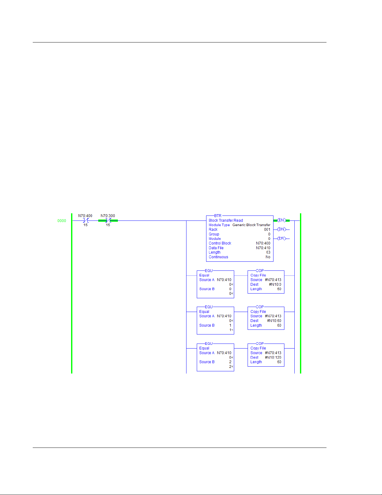
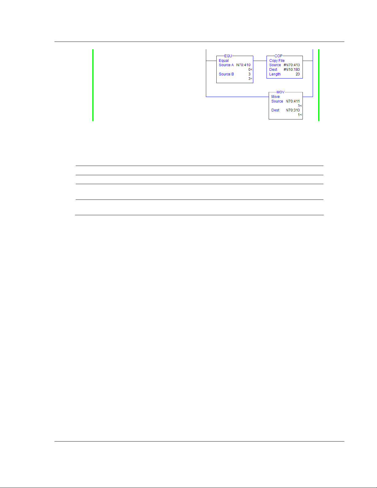
The data area follows the header section.This is the portion of the data block that
must be transferred to the user defined data table. The user is responsible for
setting up data tables and ladder logic to handle the BTR blocks. An example of
ladder logic to process four BTR blocks is displayed below:
Page 28 of 39 ProSoft Technology, Inc.
February 4, 2010
Page 29
Ladder Programming for RIO Module RIO ♦ ProLinx Gateway
Driver Manual Rockwell Automation® Remote I/O Adapter
6.3.2 BTW Ladder Rung
The BTW rung transfers data from the PLC to the ProLinx communication
module. Data is loaded into the data block by the user defined ladder logic in the
PLC. The block contains a header and a data section as defined below:
Word # Description
0 BTW block identification code to indicate data set being transferred in the data block.
1
2 to 61
This word specifies the number of valid data values in the block. The range of values
contained in this field is from 0 to 60.
These words in the block contain the data being transferred from the PLC to the
module.
The first word of the header defines the block number being transferred from the
PLC to the module. This block code identifies the data set transferred in the
block.
This block number is normally copied from the BTW identification code field in
the BTR block received by the PLC. Block numbers less than 0 are used if the
module is requesting less than two blocks of data. If the module transfers only
blocks -1 and -2, the module is configured for no write data transfers. If the
module transfers blocks -1 and 0, the module is configured for one data block (1
to 60 words of data) and only the data in block 0 is valid. The data set transferred
is identified by the block as follows:
Data Start Address = Block ID * 60
Therefore, the first word of data received in block 0 will be stored at the BTW
Start Register address specified in the user configuration of the module. The first
word of data received in block 1 will be stored at data word offset 60 from the
BTW Start Register parameter in the module.
The last word of header information defines the number of valid words of data in
the block. The simplest way to handle the ladder logic is to configure the data
write area to be an even multiple of 60 words. This prevents the ladder logic from
having to handle short block messages. The BTW operations that interface with
the RIO module always transfer the same block sizes, therefore, there is no
optimization by setting the data area to a smaller size. In fact, the added code in
the ladder logic may slow the data transfer operation.
ProSoft Technology, Inc. Page 29 of 39
February 4, 2010
Page 30

RIO ♦ ProLinx Gateway Ladder Programming for RIO Module
Rockwell Automation® Remote I/O Adapter Driver Manual
The data area follows the header section. This portion of the data block is filled in
by the user ladder logic in the PLC. This information is transferred from the PLC
and placed in the RIO communication module's database. An example of ladder
logic to process four BTW blocks is displayed below:
Page 30 of 39 ProSoft Technology, Inc.
February 4, 2010
Page 31

Support, Service & Warranty RIO ♦ ProLinx Gateway
Driver Manual Rockwell Automation® Remote I/O Adapter
7 Support, Service & Warranty
In This Chapter
How to Contact Us: Technical Support..................................................31
Return Material Authorization (RMA) Policies and Conditions...............32
LIMITED WARRANTY...........................................................................34
7.1 How to Contact Us: Technical Support
ProSoft Technology, Inc. (ProSoft) is committed to providing the most efficient
and effective support possible. Before calling, please gather the following
information to assist in expediting this process:
1 Product Version Number
2 System architecture
3 Network details
If the issue is hardware related, we will also need information regarding:
1 Module configuration and associated ladder files, if any
2 Module Operation
o Configuration/Debug status information
o LED patterns
3 Details about the serial, Ethernet or fieldbus devices interfaced with, if any.
Note: For technical support calls within the United States, an after-hours answering system allows
pager access to one of our qualified technical and/or Application Support Engineers at any time to
answer your questions.
Internet
Asia Pacific
(location in Malaysia)
Asia Pacific
(location in China)
Europe
(location in Toulouse,
France)
Europe
(location in Dubai, UAE)
Web Site: www.prosoft-technology.com/support
E-mail address: support@prosoft-technology.com
Tel: +603.7724.2080, E-mail:
Languages spoken include: Chinese, English
Tel: +86.21.5187.7337 x888, E-mail:
Languages spoken include: Chinese, English
Tel: +33 (0) 5.34.36.87.20,
E-mail:
Languages spoken include: French, English
Tel: +971-4-214-6911,
E-mail: mea@prosoft-technology.com
Languages spoken include: English, Hindi
support.EMEA@prosoft-technology.com
asiapc@prosoft-technology.com
asiapc@prosoft-technology.com
ProSoft Technology, Inc. Page 31 of 39
February 4, 2010
Page 32

RIO ♦ ProLinx Gateway Support, Service & Warranty
Rockwell Automation® Remote I/O Adapter Driver Manual
North America
(location in California)
Latin America
(Oficina Regional)
Latin America
(location in Puebla, Mexico)
Brasil
(location in Sao Paulo)
Tel: +1.661.716.5100,
E-mail: support@prosoft-technology.com
Languages spoken include: English, Spanish
Tel: +1-281-2989109,
E-Mail:
Languages spoken include: Spanish, English
Tel: +52-222-3-99-6565,
E-mail:
Languages spoken include: Spanish
Tel: +55-11-5083-3776,
E-mail:
Languages spoken include: Portuguese, English
latinam@prosoft-technology.com
soporte@prosoft-technology.com
brasil@prosoft-technology.com
7.2 Return Material Authorization (RMA) Policies and Conditions
The following RMA Policies and Conditions (collectively, "RMA Policies") apply to
any returned Product. These RMA Policies are subject to change by ProSoft
without notice. For warranty information, see Limited Warranty (page
event of any inconsistency between the RMA Policies and the Warranty, the
Warranty shall govern.
34). In the
7.2.1 All Product Returns:
a) In order to return a Product for repair, exchange or otherwise, the
Customer must obtain a Return Material Authorization (RMA) number
from ProSoft and comply with ProSoft shipping instructions.
b) In the event that the Customer experiences a problem with the Product for
any reason, Customer should contact ProSoft Technical Support at one of
the telephone numbers listed above (page
Engineer will request that you perform several tests in an attempt to
isolate the problem. If after completing these tests, the Product is found to
be the source of the problem, we will issue an RMA.
c) All returned Products must be shipped freight prepaid, in the original
shipping container or equivalent, to the location specified by ProSoft, and
be accompanied by proof of purchase and receipt date. The RMA number
is to be prominently marked on the outside of the shipping box. Customer
agrees to insure the Product or assume the risk of loss or damage in
transit. Products shipped to ProSoft using a shipment method other than
that specified by ProSoft, or shipped without an RMA number will be
returned to the Customer, freight collect. Contact ProSoft Technical
Support for further information.
d) A 10% restocking fee applies to all warranty credit returns, whereby a
Customer has an application change, ordered too many, does not need,
etc. Returns for credit require that all accessory parts included in the
original box (i.e.; antennas, cables) be returned. Failure to return these
items will result in a deduction from the total credit due for each missing
item.
31). A Technical Support
Page 32 of 39 ProSoft Technology, Inc.
February 4, 2010
Page 33

Support, Service & Warranty RIO ♦ ProLinx Gateway
Driver Manual Rockwell Automation® Remote I/O Adapter
7.2.2 Procedures for Return of Units Under Warranty:
A Technical Support Engineer must approve the return of Product under
ProSoft’s Warranty:
a) A replacement module will be shipped and invoiced. A purchase order will
be required.
b) Credit for a product under warranty will be issued upon receipt of
authorized product by ProSoft at designated location referenced on the
Return Material Authorization
i. If a defect is found and is determined to be customer generated, or if
the defect is otherwise not covered by ProSoft’s warranty, there will
be no credit given. Customer will be contacted and can request
module be returned at their expense;
ii. If defect is customer generated and is repairable, customer can
authorize ProSoft repair the unit by providing a purchase order for
30% of the current list price plus freight charges, duties and taxes as
applicable.
7.2.3 Procedures for Return of Units Out of Warranty:
a) Customer sends unit in for evaluation to location specified by ProSoft,
freight prepaid.
b) If no defect is found, Customer will be charged the equivalent of $100
USD, plus freight charges, duties and taxes as applicable. A new
purchase order will be required.
c) If unit is repaired, charge to Customer will be 30% of current list price
(USD) plus freight charges, duties and taxes as applicable. A new
purchase order will be required or authorization to use the purchase order
submitted for evaluation fee.
The following is a list of non-repairable units:
o 3150 - All
o 3750
o 3600 - All
o 3700
o 3170 - All
o 3250
o 1560 - Can be repaired, only if defect is the power supply
o 1550 - Can be repaired, only if defect is the power supply
o 3350
o 3300
o 1500 - All
ProSoft Technology, Inc. Page 33 of 39
February 4, 2010
Page 34

RIO ♦ ProLinx Gateway Support, Service & Warranty
Rockwell Automation® Remote I/O Adapter Driver Manual
7.3 LIMITED WARRANTY
This Limited Warranty ("Warranty") governs all sales of hardware, software and
other products (collectively, "Product") manufactured and/or offered for sale by
ProSoft, and all related services provided by ProSoft, including maintenance,
repair, warranty exchange, and service programs (collectively, "Services"). By
purchasing or using the Product or Services, the individual or entity purchasing or
using the Product or Services ("Customer") agrees to all of the terms and
provisions (collectively, the "Terms") of this Limited Warranty. All sales of
software or other intellectual property are, in addition, subject to any license
agreement accompanying such software or other intellectual property.
7.3.1 What Is Covered By This Warranty
a) Warranty On New Products: ProSoft warrants, to the original purchaser,
that the Product that is the subject of the sale will (1) conform to and
perform in accordance with published specifications prepared, approved
and issued by ProSoft, and (2) will be free from defects in material or
workmanship; provided these warranties only cover Product that is sold as
new. This Warranty expires three (3) years from the date of shipment for
Product purchased on or after January 1st, 2008, or one (1) year from the
date of shipment for Product purchased before January 1st, 2008 (the
"Warranty Period"). If the Customer discovers within the Warranty Period
a failure of the Product to conform to specifications, or a defect in material
or workmanship of the Product, the Customer must promptly notify
ProSoft by fax, email or telephone. In no event may that notification be
received by ProSoft later than 39 months from date of original shipment.
Within a reasonable time after notification, ProSoft will correct any failure
of the Product to conform to specifications or any defect in material or
workmanship of the Product, with either new or remanufactured
replacement parts. ProSoft reserves the right, and at its sole discretion,
may replace unrepairable units with new or remanufactured equipment.
All replacement units will be covered under warranty for the 3 year period
commencing from the date of original equipment purchase, not the date of
shipment of the replacement unit. Such repair, including both parts and
labor, will be performed at ProSoft’s expense. All warranty service will be
performed at service centers designated by ProSoft.
b) Warranty On Services: Materials and labor performed by ProSoft to repair
a verified malfunction or defect are warranteed in the terms specified
above for new Product, provided said warranty will be for the period
remaining on the original new equipment warranty or, if the original
warranty is no longer in effect, for a period of 90 days from the date of
repair.
Page 34 of 39 ProSoft Technology, Inc.
February 4, 2010
Page 35

Support, Service & Warranty RIO ♦ ProLinx Gateway
Driver Manual Rockwell Automation® Remote I/O Adapter
7.3.2 What Is Not Covered By This Warranty
a) ProSoft makes no representation or warranty, expressed or implied, that
the operation of software purchased from ProSoft will be uninterrupted or
error free or that the functions contained in the software will meet or
satisfy the purchaser’s intended use or requirements; the Customer
assumes complete responsibility for decisions made or actions taken
based on information obtained using ProSoft software.
b) This Warranty does not cover the failure of the Product to perform
specified functions, or any other non-conformance, defects, losses or
damages caused by or attributable to any of the following: (i) shipping; (ii)
improper installation or other failure of Customer to adhere to ProSoft’s
specifications or instructions; (iii) unauthorized repair or maintenance; (iv)
attachments, equipment, options, parts, software, or user-created
programming (including, but not limited to, programs developed with any
IEC 61131-3, "C" or any variant of "C" programming languages) not
furnished by ProSoft; (v) use of the Product for purposes other than those
for which it was designed; (vi) any other abuse, misapplication, neglect or
misuse by the Customer; (vii) accident, improper testing or causes
external to the Product such as, but not limited to, exposure to extremes
of temperature or humidity, power failure or power surges; or (viii)
disasters such as fire, flood, earthquake, wind and lightning.
c) The information in this Agreement is subject to change without notice.
ProSoft shall not be liable for technical or editorial errors or omissions
made herein; nor for incidental or consequential damages resulting from
the furnishing, performance or use of this material. The user guide
included with your original product purchase from ProSoft contains
information protected by copyright. No part of the guide may be duplicated
or reproduced in any form without prior written consent from ProSoft.
7.3.3 Disclaimer Regarding High Risk Activities
Product manufactured or supplied by ProSoft is not fault tolerant and is not
designed, manufactured or intended for use in hazardous environments requiring
fail-safe performance including and without limitation: the operation of nuclear
facilities, aircraft navigation of communication systems, air traffic control, direct
life support machines or weapons systems in which the failure of the product
could lead directly or indirectly to death, personal injury or severe physical or
environmental damage (collectively, "high risk activities"). ProSoft specifically
disclaims any express or implied warranty of fitness for high risk activities.
ProSoft Technology, Inc. Page 35 of 39
February 4, 2010
Page 36

RIO ♦ ProLinx Gateway Support, Service & Warranty
Rockwell Automation® Remote I/O Adapter Driver Manual
7.3.4 Intellectual Property Indemnity
Buyer shall indemnify and hold harmless ProSoft and its employees from and
against all liabilities, losses, claims, costs and expenses (including attorney’s
fees and expenses) related to any claim, investigation, litigation or proceeding
(whether or not ProSoft is a party) which arises or is alleged to arise from Buyer’s
acts or omissions under these Terms or in any way with respect to the Products.
Without limiting the foregoing, Buyer (at its own expense) shall indemnify and
hold harmless ProSoft and defend or settle any action brought against such
Companies to the extent based on a claim that any Product made to Buyer
specifications infringed intellectual property rights of another party. ProSoft
makes no warranty that the product is or will be delivered free of any person’s
claiming of patent, trademark, or similar infringement. The Buyer assumes all
risks (including the risk of suit) that the product or any use of the product will
infringe existing or subsequently issued patents, trademarks, or copyrights.
a) Any documentation included with Product purchased from ProSoft is
protected by copyright and may not be duplicated or reproduced in any
form without prior written consent from ProSoft.
b) ProSoft’s technical specifications and documentation that are included
with the Product are subject to editing and modification without notice.
c) Transfer of title shall not operate to convey to Customer any right to make,
or have made, any Product supplied by ProSoft.
d) Customer is granted no right or license to use any software or other
intellectual property in any manner or for any purpose not expressly
permitted by any license agreement accompanying such software or other
intellectual property.
e) Customer agrees that it shall not, and shall not authorize others to, copy
software provided by ProSoft (except as expressly permitted in any
license agreement accompanying such software); transfer software to a
third party separately from the Product; modify, alter, translate, decode,
decompile, disassemble, reverse-engineer or otherwise attempt to derive
the source code of the software or create derivative works based on the
software; export the software or underlying technology in contravention of
applicable US and international export laws and regulations; or use the
software other than as authorized in connection with use of Product.
f) Additional Restrictions Relating To Software And Other Intellectual
Property
In addition to compliance with the Terms of this Warranty, Customers
purchasing software or other intellectual property shall comply with any
license agreement accompanying such software or other intellectual
property. Failure to do so may void this Warranty with respect to such
software and/or other intellectual property.
7.3.5 Disclaimer of all Other Warranties
The Warranty set forth in What Is Covered By This Warranty (page 34) are in lieu
of all other warranties, express or implied, including but not limited to the implied
warranties of merchantability and fitness for a particular purpose.
Page 36 of 39 ProSoft Technology, Inc.
February 4, 2010
Page 37

Support, Service & Warranty RIO ♦ ProLinx Gateway
Driver Manual Rockwell Automation® Remote I/O Adapter
7.3.6 Limitation of Remedies **
In no event will ProSoft or its Dealer be liable for any special, incidental or
consequential damages based on breach of warranty, breach of contract,
negligence, strict tort or any other legal theory. Damages that ProSoft or its
Dealer will not be responsible for include, but are not limited to: Loss of profits;
loss of savings or revenue; loss of use of the product or any associated
equipment; loss of data; cost of capital; cost of any substitute equipment,
facilities, or services; downtime; the claims of third parties including, customers of
the Purchaser; and, injury to property.
** Some areas do not allow time limitations on an implied warranty, or allow the exclusion or
limitation of incidental or consequential damages. In such areas, the above limitations may not
apply. This Warranty gives you specific legal rights, and you may also have other rights which vary
from place to place.
7.3.7 Time Limit for Bringing Suit
Any action for breach of warranty must be commenced within 39 months
following shipment of the Product.
7.3.8 No Other Warranties
Unless modified in writing and signed by both parties, this Warranty is
understood to be the complete and exclusive agreement between the parties,
suspending all oral or written prior agreements and all other communications
between the parties relating to the subject matter of this Warranty, including
statements made by salesperson. No employee of ProSoft or any other party is
authorized to make any warranty in addition to those made in this Warranty. The
Customer is warned, therefore, to check this Warranty carefully to see that it
correctly reflects those terms that are important to the Customer.
7.3.9 Allocation of Risks
This Warranty allocates the risk of product failure between ProSoft and the
Customer. This allocation is recognized by both parties and is reflected in the
price of the goods. The Customer acknowledges that it has read this Warranty,
understands it, and is bound by its Terms.
7.3.10 Controlling Law and Severability
This Warranty shall be governed by and construed in accordance with the laws of
the United States and the domestic laws of the State of California, without
reference to its conflicts of law provisions. If for any reason a court of competent
jurisdiction finds any provisions of this Warranty, or a portion thereof, to be
unenforceable, that provision shall be enforced to the maximum extent
permissible and the remainder of this Warranty shall remain in full force and
effect. Any cause of action with respect to the Product or Services must be
instituted in a court of competent jurisdiction in the State of California.
ProSoft Technology, Inc. Page 37 of 39
February 4, 2010
Page 38

RIO ♦ ProLinx Gateway Support, Service & Warranty
Rockwell Automation® Remote I/O Adapter Driver Manual
Page 38 of 39 ProSoft Technology, Inc.
February 4, 2010
Page 39

Support, Service & Warranty RIO ♦ ProLinx Gateway
Driver Manual Rockwell Automation® Remote I/O Adapter
M
Module Internal Database • 6
Index
[
[RIO] • 14
A
All Product Returns: • 30
All ProLinx® Products • 2
Allocation of Risks • 35
B
BTR Ladder Rung • 25
BTR Register Count • 15
BTR Start Register • 15
BTW Ladder Rung • 26
BTW Register Count • 15
BTW Start Register • 15
C
Controlling Law and Severability • 35
D
Data Rate • 17
Disclaimer of all Other Warranties • 34
Disclaimer Regarding High Risk Activities • 33
Downloading a File from PC to the module • 13
G
Group Number • 17
H
How to Contact Us
Technical Support • 29, 30
I
Important Installation Instructions
MVI and ProLinx products • 2
Initial Setup • 22
Input and Output Data Images • 24
Input Word 1 ... 7 • 17
Install ProSoft Configuration Builder Software • 10
Intellectual Property Indemnity • 34
L
Ladder Logic Programming • 24
Ladder Programming for RIO Module • 22
Last Rack • 17
LED Indicators • 19
Limitation of Remedies ** • 35
LIMITED WARRANTY • 30, 32
N
No Other Warranties • 35
O
Output Word 1 ... 7 • 18
P
Pinouts • 2, 18
Printing a Configuration File • 13
Procedures for Return of Units Out of Warranty: • 31
Procedures for Return of Units Under Warranty: • 31
ProLinx Gateways with Ethernet Ports • 2
ProSoft Technology® Product Documentation • 3
Protocol Functional Overview • 6
Protocol Functional Specifications • 9
R
Rack Number • 15
Rack Size • 15
Remote I/O Access to Database • 7
Remote I/O Adapter Cable Connection • 18
Remote I/O Adapter Error Codes • 21
Remote I/O Adapter Status and Error Data • 20
Remote I/O Interface • 19
Remote I/O Port • 6
Remote I/O Specifications • 9
Return Material Authorization (RMA) Policies and
Conditions • 30
RIO Protocol Configuration • 10
S
Set Up the Project • 11
Support, Service & Warranty • 29
T
Time Limit for Bringing Suit • 35
To Configure Module Parameters • 12
To Create Optional Comment Entries • 12
To Order a ProLinx Plus gateway with the -WEB
option: • 2
To upgrade a previously purchased Series C model: •
2
W
What Is Covered By This Warranty • 32, 34
What Is Not Covered By This Warranty • 33
Y
Your Feedback Please • 3
ProSoft Technology, Inc. Page 39 of 39
February 4, 2010
 Loading...