

Page 1
CarAudio
CMD-170
TABLEOFCONTENTS
Page
TechnicalSpecifications....................................................1-2
Measurementsetup....................................................1-3
ServiceAids,SafetyInstruction,etc....................1-4to1-5
Preparations&Controls.....................................1-6to1-9
Maintenance&Troubleshooting.................................1-10
DisassemblyInstructions&Servicepositions..................2
SetBlockdiagram.........................................................3
SetWiringdiagram........................................................4
KeyBoard.....................................................................5
ServoBoard..................................................................6
MainBoard...................................................................7
SetMechanicalExplodedview&partslist........................8
......
......
......
......
......
......
......
......
......
......
......
Page 2

SPECIFICATIONS
1-2
General
Powersupply:
Maximumpoweroutput:
Continuouspoweroutput:
Suitablespeakerimpedance:
Pre-Ampoutputvoltage:
Fuse:
Dimensions(WxHxD)
Weight:
FMStereoRadio
Frequencyrange:
Usablesensitivity:
quietingsensitivity(S/N=50dB):
Frequencyresponse:
Stereoseparation:
Imageresponseratio:
IFresponseratio:
Signal/noiseratio
12VDC(11V-16V)
Testvoltage14.4V,negativeground
50Wx4channels
25Wx4channels(4,10%T.H.D.)Ω
4-8ohm
2.0V(CDplaymode:1KHz,0dB,10Kload)Ω
15A
178x50x162mm
1.7kg
87.5-108.0MHz(EUROPEmode)
65.0-74.0MHz(OIRTmode)
8dB
μ
12dB
μ
30Hz-15kHz
30dB(1kHz)
50dB
70dB
55dB
Components
Mountingcollar
MachinescrewsM5x6mm
Mountingbolt(50mm)
Wireconnector
Removablefaceplatecase
Trimplate
L-key
Operatinginstructions
Rubbercushion
1
4
1
1
1
1
2
1
1
DiscPlayer
System:
Frequencyresponse:
Signal/noiseratio:
Totalharmonicdistortion:
Wowandflutter:
Channelseparation:
Note:Specificationsanddesignaresubjecttochange
withoutnoticeforproductimprovements.
Discdigitalaudiosystem
20Hz-20kHz
>86dB
Lessthan0.20%(1kHz)
Belowmeasurablelimits
>60dB
Page 3
PREPARATIONS
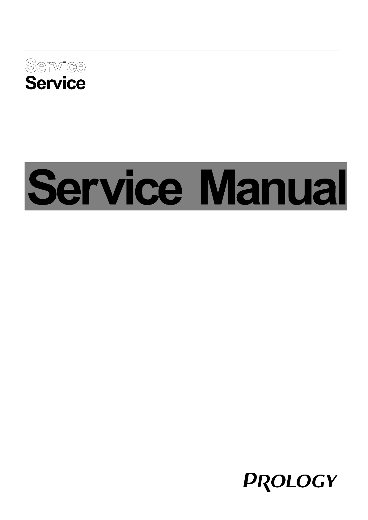
WiringDiagram
1-6
Purple
Black
Stripe
Antenna
GrayGreenPurple/
Black
Stripe
White/
Black
Stripe
Fuse15A
Connector
Line-out(Gray)
R(Red)
Amplifier
L(White)
ISOConnector
ForsomeVW/AudiorOpel(Vauxhall)
carmodels,youmayneedtomodify
wiringofthesuppliedpowercordas
Yellow
Black
Blue
Red
WhiteGray/
Green/
Black
Stripe
Tocarbattery(+)Continuous+12VDC
GroundLead
Motor/ElectricAntennarelaycontrolLead
AmplifierrelaycontrolLead
Ignitionkey
+12VDCWhenON/ACC
illustrated,orelsethememoryofthe
unitmaybelostafteryoupoweroff.
Contactyourauthorizedcardealer
beforeinstallingthisunit.
Originalwiring
Yellow Yellow
Red
Modifiedwiring
YellowYellow
Red
Red
Red
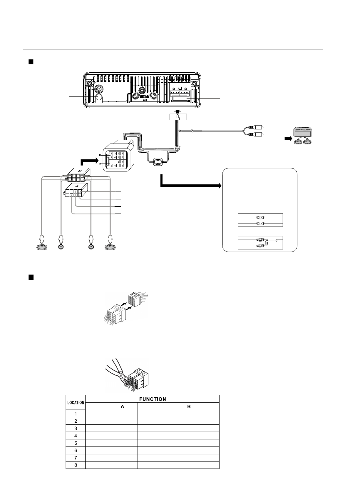
UsingtheISOConnector
1.IfyourcarisequippedwiththeISOconnector,thenconnecttheISOconnectorsasillustrated.
2.ForconnectionswithouttheISOconnectors,checkthewiringinthevehiclecarefully
incorrectconnectionmaycauseseriousdamagetothisunit.
Cuttheconnector,connectthecoloredleadsofthepowercordtothecarbattery,
codetablebelowforspeakerandpowercableconnections
ConnectorConnector
RearRight(+)---Purple
RearRight(-)---Purple/BlackStripe
FrontRight(+)---Gray
ACC+/red
AutoAntenna/blue
FrontRight(-)---Gray/BlackStripe
FrontLeft(+)---White
FrontLeft((-)---White/BlackStripe
Battery12V(+)/yellow
Ground/black
RearLeft(+)---Green
RearLeft(-)---Green/BlackStripe
beforeconnecting,
asshowninthecolour
Page 4

KEYBOARD-CIRCUITDIAGRAM
5-25-2
Page 5

6-26-2
SERVOBOARD-CIRCUITDIAGRAM
Page 6

MAINBOARD-CIRCUITDIAGRAM
7-27-2
Page 7

www.mobiteh.com
 Loading...