


MOBILE STAGE STAND
PLWIN60C
2

INDICE
1. INTRODUZIONE………………………………………………………………………………... 3
2. DATI TECNICI…………………………………………………………………………………... 3
3. POSIZIONAMENTO DEL SOLLEVATORE………………………………………………….. 4
4. SOLLEVAMENTO………………………………………………………………………………. 5
5. INSERIMENTO E DISINSERIMENTO DEL CARICO………………………………………. 5
6. CHIUSURA E TRASPORTO DEL SOLLEVATORE………………………………………... 6
7. IMPORTANTI MISURE DI SICUREZZA……………………………………………………... 6
8. RESPONSABILITA’…………………………………………………………………………….. 7
9. AVVERTENZE………………………………………………………………………………….. 8
INDEX
1. INTRODUCTION………………………………………………………………………………...9
2. TECHNICAL DATA……………………………………………………………………………... 9
3. POSITIONING THE STAND……………….………………………………………………….. 10
4. LIFTING THE MASTS…………………………………………………………………………. 11
5. ADDING AND LOWERING OF THE LOAD…………………………………………………. 11
6. RESTORING AND TRANSPORT THE STAND……..……………………………………... 12
7. IMPORTANT SAFETY MEASURES….……………………………………………………... 12
8. THE RESPONSIBILITY OF THE FAULT…………………………………………………….. 13
9. WARNING……………………………………………………………………………………….. 14
2
Rev.04- 04/11
1. INTRODUZIONE
Grazie per aver scelto il sollevatore PROEL PLWIN60C
Ideale per sollevare apparecchiature luminose, sistemi audio e truss in alluminio
2. DATI TECNICI
Ogni PLWIN60C è costituito da:
- 4 gambe indipendenti regolabili per garantire la massima verticalità su ogni superficie
- Argano manuale con frizione di sicurezza
- 3 colonne telescopiche per il sollevamento
- Foro femmina universale 28mm
Capacità di carico massima: 100 Kg uso all’aperto (vento max 50 km/h)
150 Kg uso al chiuso (assenza di vento)
Altezza massima: 5.8 m
Altezza minima: 1.95 m
Ingombro base: 2.7 m
Peso: 70 kg
Altezza chiuso: 1.95 m
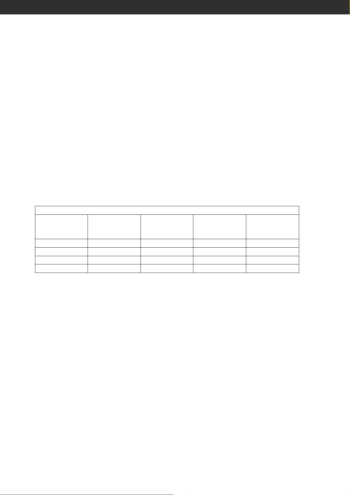
TABELLA DI CARICO PER PLWIN60C
Deformazione
Altezza (mm) Vento 0 km/h Vento 50 km/h Zavorra (kg)
max (mm), per
vento 50 km/h
5800 150 100 200 90
4500 200 115 130 45
3100 250 150 70 12
1950 280 230 30 1
3
3. POSIZIONAMENTO DEL SOLLEVATORE
1. Posizionare il sollevatore in verticale.
2. Assicurarsi che il terreno sia solido e compatto per evitare che i piedi possano affondarvi. La stabilità
del sollevatore è di primaria importanza per la sicurezza.
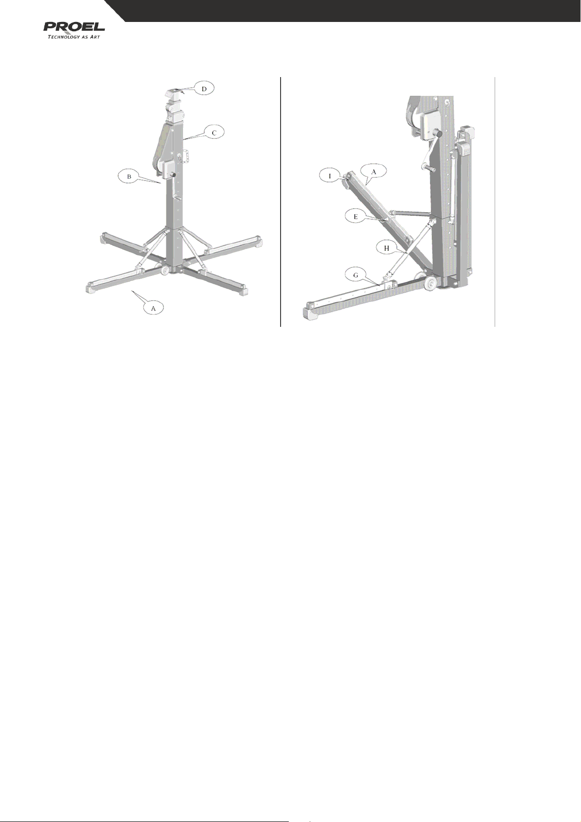
3. Tirare il pin a molla (E) ed aprire i piedi di appoggio fino alla posizione orizzontale. Se l’esatta posizione
non è stata raggiunta, utilizzare i bracci regolatori (H).
4. Inserire il pin a molla (E) nell’apposito foro della gamba (A) facendo attenzione che la slitta (G) sia
bloccata.
5. Utilizzare i bracci regolatori (H) per assicurarsi che i piedi (I) tocchino perfettamente il terreno.
6. Ripetere l’operazione su tutti i piedi fino a che la base non sia leggermente sollevata da terra.
7. Quando il sollevatore è in sicurezza ed in perfetta posizione verticale, verificare di nuovo che le slitte
(G) sui piedi siano bloccate e che il pin a molla (E) sia bloccato nel rispettivo foro. La stabilità del
sollevatore è di primaria importanza per la sicurezza.
4
4. SOLLEVAMENTO
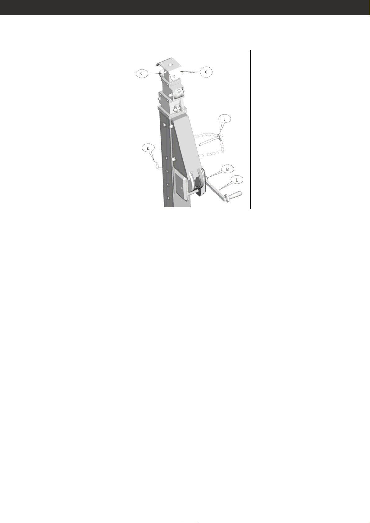
1. Rimuovere il pin (J) dalla colonna estraendo la coppiglia (K)
2. Se il sollevatore è fornito con la manovella dell’argano smontata, montarla come segue:
- rimuovere il tappo rosso dalla manovella (L);
- rimuovere la vite e la rondella dal pin (M);
- avvitare la manovella senza applicare forza sul pin, fino allo stop;
- fissare la manovella avvitando le vite con la rondella e la molla, nel corretto ordine sul pin (M). Per
serrare usare una chiave dinamometrica a 25Nm;
- verificare che la manovella sia montata correttamente: essa deve poter ruotare liberamente per ½ giro
con la ruota degli ingranaggi ferma;
- rimettere il tappo rosso sulla manovella.
3. girare la manovella dell’argano in senso orario per alzare il sollevatore, viceversa in senso antiorario
per abbassare.
4. Quando il carico è all’altezza desiderata, inserire sempre il pin (J) nel foro appena disponibile
ricordandosi di inserire anche la coppiglia (K)
5. Girare la manovella leggermente in senso antiorario per evitare che tutto il peso sia sule cinghie di
sollevamento.
5. INSERIMENTO E DISINSERIMENTO DEL CARICO
1. Assicurare il carico serrando la manopola (N). Nel caso di utilizzo di una barra a T, bilanciare il carico.
2. Per uso all’esterno assicurare lo stativo con delle funi di sicurezza (non fornite) utilizzando i fori (O).
Evitare di caricare riflettori troppo larghi.
3. Per disinserire il carico seguire la procedura inversa.
5

6. CHIUSURA E TRASPORTO DEL SOLLEVATORE
1. Eseguire la procedura inversa al sollevamento per abbassare il sollevatore, ricordandosi di inserire
sempre il pin (J)e la coppiglia (K) per evitare il movimento della colonna.
2. Eseguire la procedura inversa per la chiusura di piedi. Assicurarsi che in posizione di chiusura i pin a
molla (E) siano reinseriti nel rispettivo foro in modo che i piedi siano bloccati in posizione di chi usura.
Serrare poi i bracci regolatori (H) in modo da garantire la verticalità di tutti i piedi.
3. Per la movimentazione utilizzare la maniglia (P) e le ruote (Q).
7. IMPORTANTI MISURE DI SICUREZZA E LIMITAZIONI D’USO
1. Rispettare le indicazioni del fornitore riguardo i limiti di carico e tutte le norme relative alla sicurezza. La
scelta delle truss da utilizzare deve essere fatta compatibilmente al carico da applicare.
2. Adeguate misure di sicurezza devono essere prese, per le persone che lavorano nei pressi dei carichi
sospesi; per ogni apparecchiatura sospesa alle truss deve essere utilizzato un apposito cavo di
sicurezza in acciaio.
3. Le portate indicate si intendono in assenza di carico neve o carico da sisma.
4. Nel calcolo delle portate, l’operatore deve tener conto anche del peso del traliccio e sottrarre il peso di
questo alla portata massima dello stativo per avere il massimo carico effettivamente applicabile.
5. Il massimo carico applicabile è da intendersi statico, verticale ed in asse. L’area del carico non deve
superare 1.0 mq frontalmente.
6. Il carico appeso deve essere statico e ne deve essere impedita ogni oscillazione.
7. Per carichi diversi da quelli specificati o per superfici eccedenti, deve essere realizzata una nuova
relazione di calcolo a cura di tecnico competente ed abilitato.
8. La struttura deve essere appoggiata su di un piano perfettamente orizzontale e di sufficiente solidità.
9. Per vento superiore a 50 km/h (13,89 m/s) la struttura diviene instabile e pertanto deve essere
abbassato a terra il carico. E’ necessaria pertanto la presenza di un tecnico specializzato adde tto ad un
controllo costante della struttura.
6

10. E’ necessario predisporre pesi di zavorra sulla base della struttura, applicabili anche a mezzo di cavi
per evitare il ribaltamento della stessa. Lo schema di carico delle zavorre va valutato in base
all’ubicazione della struttura.
11. La struttura deve essere correttamente montata secondo le istruzioni riportate nel presente manuale.
12. Assicurarsi di ottemperare alle norme di sicurezza previste in normativa per il montaggio e lo
smontaggio delle strutture.
13. Prima di montare la struttura assicurarsi di essere in possesso di tutte le autorizzazioni degli enti
preposti al controllo o previsti dalla normativa.
14. Tutte le apparecchiature elettriche appese sul sollevatore devono soddisfare ai relativi requisiti di
sicurezza.
15. Il sollevatore deve essere utilizzato solo se in perfetta posizione verticale.
16. Il sollevatore non deve essere mai utilizzato su una superficie in pendenza.
17. Agganciare il carico al sollevatore applicando gli accessori adatti.
18. Il carico deve essere centrato o equamente distribuito sul sollevatore. Fare attenzione a che il carico
non scivoli, per evitarne la caduta.
19. Non muovere mai il sollevatore quando è carico.
20. Non utilizzare mai il sollevatore per il sollevamento di persone.
21. Non appoggiare mai una scala al sollevatore.
22. Non eccedere mai con i carichi consentiti.
23. Non utilizzare mai il sollevatore all’esterno in condizioni meteorologiche particolarmente avverse (es.
vento forte).
24. E’ molto pericoloso sollevare un carico ingombrante in condizioni di vento.
25. Il sollevatore non deve essere mai utilizzato su una superficie morbida, mobile o cedevole.
26. Tutti i meccanismi scorrevoli e rotanti (ingranaggi e perni di scorrimento), devono essere lubrificati se il
sollevatore è utilizzato in condizioni particolarmente avverse.
8. RESPONSABILITA’
1. L’uso del sollevatore in installazioni temporanee è sotto l’esclusiva responsabilità dell’operatore.
2. Durante il periodo di garanzia sarà nostra cura (o di un nostro centro di assistenza autorizzato)
effettuare le riparazioni di qualsiasi rottura dovuta a materiali difettosi.
3. La garanzia non copre i danni dovuti a: noncuranza dell’operatore; sovraccarichi. Non copre inoltre
quelle parti soggette a normale usura.
4. L’uso di ricambi non originali o modifiche non autorizzate, implicano la decadenza immediata della
garanzia.
5. La manutenzione di verifica del funzionamento e di sicurezza deve essere eseguita periodicamente
(ogni anno) a cura dell’operatore, anche in caso di utilizzo non intensivo del sollevatore.
7

9. AVVERTENZE
E’ esclusiva responsabilità dell’operatore eseguire ogni 5 anni una verifica ad invecchiamento e ad usura,
del funzionamento di tutti i meccanismi, affinché essi siano integri.
Tale verifica deve essere effettuata presso la casa costruttrice o ente preposto.
130
140
150
160
8

1. INTRODUCTION
Thank you for choosing a light stand system PLWIN60C.
It is designed to support lighting fixture, speakers, and aluminium trusses.
2. TECHNICAL DATA
All models are equipped with:
- Independently adjustable support legs ensure vertical positioning on uneven ground.
- Protected manual winch with safety friction brake
- 3 columns extended simultaneously: the first
- Universal 28mm female attachment.
Technical Data:
Maximum load: 100 kg – outdoor use (max wind speed 50 km/h)
150 kg – indoor use (no wind) – axial load
Maximum height : 5,8 m
Minimum height: 1.95 m
Footprint: 2.7 m
Weight: 70 kg
Closed size: 1.95 m
LOAD TABLE FOR PLWIN60C
Max deflection
Height (mm) Wind 0 km/h Wind 50 km/h Ballast (kg)
(mm), wind
50 km/h
5800 150 100 200 90
4500 200 115 130 45
3100 250 150 70 12
1950 280 230 30 1
9

3. POSITIONING THE STAND
1. Place the stand in the vertical position.
2. Ensure that the ground is strong enough to prevent any sinking of the stand into the ground. The
stability of the stand is of prime importance for a secure operation.
3. Pull out the spring pin (E), and flip the legs (A) from vertical position to horizontal position. If precisely
desired legs angle is not available please turn the leg-brace screw jack (H).
4. Choose the proper hole in the leg (A) and restore the spring pin (E).
5. Use the leg-brace screw jacks (H) to ensure the feet (I) touch the ground.
6. Continue the leg-brace screw jacks (H) of each leg in sequence until the base plate slightly lift off the
ground.
7. When the stand in securely positioned and vertical, check again that the leg-brace sliders(G) are
properly locked into their holes on the legs. The stability of the stand is of prime importance for a secure
operation.
10

4. LIFTING THE MASTS
1. Remove the mast pin (J) from the column extracting the split pin (K).
2. If the stand is supplied with crack (L), which is folding, dismantled, mount the crank as follow:
- Remove the red cap from the crank (L),
- Remove the screw and the washer from the pin (M),
- Screw the crank without applying force on the pin (M) until to reach the stop,
- Fix the crank, screwing the screw with the washer and the spring washer curved in corre ct ord er, on the
pin (M), holding stopped the gear wheel with a screwdriver use a dynamom etric key and lock at 25Nm.
- Check the crank is correctly mounted: the crank must freely rotate 1/2 turn with the gear wheel stopped.
- Reassemble the red cap onto the crank.
3. Turn the which crank (L) clockwise to raise the masts. Turn the winch crank (L) anti-clo ckwise to lower
the masts
4. When the load is at the required height. ALWAYS INSERT the mast pin (J) into the upper free hole
among the available; remember to insert the split pin (K).
5. Turn the winch crank(L) anti-clo ckwise a little to avoid the belt to support any load.
5. ADDING AND LOWERING OF THE LOAD
1. Secure the load in position by locking the handle (N). When using a T-bar, load should be balanced.
2. For out door use secure the stand with safety cables (not supplied) fixing them at the hole (O) in windy
condition. Avoid to load large reflectors.
3. Reverse the adding load procedure to lower of the load.
11

6. RESTORING AND TRANSPORT THE STAND
1. Reverse the lifting procedure to restore the masts, insert the mast pin (J) in the highest hole to avoid
the movement of the masts. remember to insert the split pin (K).
2. Reverse the position the stand procedure to fold up the legs. Make sure that the spring pin (E) are
restored to lock the leg-brace slider (G) to the legs (A). Tighten all of the leg-brace screw jacks (H) to
make sure all of the legs (A) are in the vertical position.
3. For moving, use handle (P) and the wheels (Q).
7. IMPORTANT SAFETY MEASURES
1. Be respect the factory guidelines concerning the load limits as well as the safety codes of material and
staff. The choice of trussing and the stand capacity must be adapted to the load.
2. Adequate safety measures must be taken when people work under the loads carried by the truss and
the stands, safety steel slings and chains must be used on every item hung on the truss.
3. The indicated loads are without load of snow and load of earthquake.
4. The operator must take into account the weight of the holding truss on the stand and deduct it from its
allowable load.
5. The maximum load applied shall be considered static, vertical and axial. The area of the load should
not exceed 1.0 m on the front.
6. The suspended load must be static and it must be prevented each movement.
7. For other loads than those specified and for surfaces bigger than 1,0 mq on the front, it must be
realized a new technical report by competent and qualified technician.
8. The structure must be placed on a perfectly horizontal plane and with sufficient strength.
9. With winds exceeding 50 km / h (13.89 m / s) the structure becomes unstable and the load must be
lowered to the ground. Therefore it is required the presence of a technician assigned to a constant
control of structure.
12

10. It is necessary to provide some ballasts on the base of the structure. It is possible also apply them by
using cables. It is important to prevent roll over of the structure. The diagram of the ballasts must be
evaluated according to the location of the structure.
11. The structure must be properly assembled and installed according to the instructions in this manual.
12. Be sure to comply with safety standards in legislation for the assembly and disassembly of structures.
13. Before assembling and installing the structure it must be sure to have all the permissions of the
responsible institutions or required by law.
14. All electrical devices hung on the stand or by the stand must absolutely conform to the technical codes
concerning electrical devices (EC NORMS).
15. The stand must only be operated in an exactly vertical position.
16. The stand do not allow to be used on a sloping surface.
17. Load the stand using only adaptive accessories.
18. The load must be centred or evenly distributed on the stand, be careful that the load does not slide to
avoid any overhang of the load.
19. Never move the stand when it is loaded.
20. Never use the stand to carry people.
21. Never lean a ladder on the stand.
22. Never exceed the allowed load limits.
23. Never use the stand in outdoor in typhoon weather condition.
24. It is dangerous to support a very large size load in windy outdoor condition.
25. The stand do not allow to be used on a soft, moveable or
yielding surface.
26. All sliding and rotating mechanisms used in bad weather must be regularly lubricated.
8. THE RESPONSIBILITY OF THE FAULT
1. The use of trussing and lifting equipment in temporary or mobile installation is the sole responsibility of
the operator.
2. During the guarantee period, we or one of our contract service organizations undertake to repair, free of
charge any damage attributable to faulty materials.
3. The guarantee does not cover damage due to negligent handling, overload or parts subject to normal
wear and tear.
4. The fitting of replacement parts not supplied by us or modifications of our design by third parties
invalidates the guarantee.
5. The maintenance of security and verification of operation should be performed regularly (annually) by
the operator, even in case of non-intensive use of the lift
13

9. WARNING
It is the sole responsibility of the operator to perform a review every five years to aging and wear and verify
the operation of all mechanisms, so that they are intact.
This verification must be performed by the manufacturer or authorized service center.
1300
1400
1500
1600
14

15 16 16

 Loading...