

Page 1
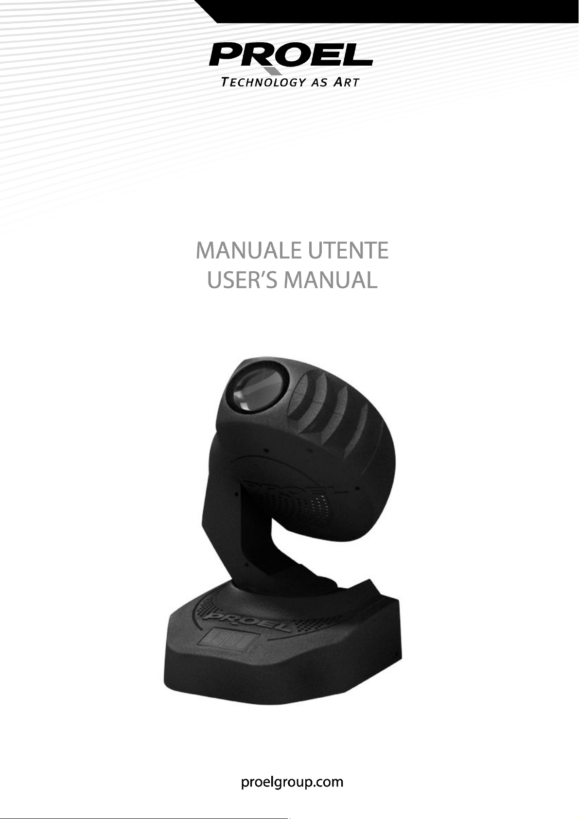
TESTAMOBILE 150
MONOBRACCIO
PLML150E
Page 2
INDICE
INDICE
INDICEINDICE
NORME DI SICUREZZA ............................................................................................................................................3
AVVERTENZE...............................................................................................................................................................3
ISTRUZIONI DI SICUREZZA ....................................................................................................................................4
FUNZIONI OPERATIVE .............................................................................................................................................5
CARATTERISTICHE.....................................................................................................................................................6
INSTALLAZIONE.........................................................................................................................................................6
MENU DISPLAY...........................................................................................................................................................7
SCHEMA DI CONNESSIONE DMX........................................................................................................................9
PERSONALITY........................................................................................................................................................... 10
MODALITÀ 8 CANALI............................................................................................................................................ 12
MANUTENZIONE .................................................................................................................................................... 12
SPECIFICHE TECNICHE.......................................................................................................................................... 13
Tutte le specifiche riportate nel presente manuale sono soggette a
variazioni senza preavviso
Rev. 00 – 25/2008
Page 3

Nel continuo sforzo di migliorare la qualità dei suoi prodotti, la Proel SpA
può introdurre cambiamenti tecnici nel corso della produzione. Pertanto le
specifiche tecniche ed il disegno possono subire variazioni senza
preavviso. La Proel SpA non è responsabile dei danni derivanti da uso
improprio o diverso da quello previsto di questo prodotto.
NORME DI SICUREZZA
Per garantire il corretto e duraturo funzionamento della testa mobile
PLML150E,
presente manuale.
Osservare le seguenti norme di sicurezza durante l’uso e le operazioni di
manutenzione.
- Questo prodotto non è adatto all’uso domestico.
- Conservare il prodotto in un luogo asciutto, al riparo da acqua o
umidità.
- Non toccare il prodotto con le mani bagnate.
- Non smontare o modificare il prodotto.
- Se il prodotto viene a contatto con liquidi, scollegare immediatamente
l’alimentazione.
- Non aprire il prodotto: all’interno non vi sono parti manutenibili
dall’utente.
- Manovrare il prodotto con cautela, eventuali urti o sollecitazioni
possono provocare malfunzionamenti.
, si consiglia di leggere e conservare con particolare cura il
, ,
AVVERTENZE
- Prima di mettere in funzione l’apparecchiatura, verificare che non abbia
subito danni durante il trasporto. In presenza di eventuali danni, non
procedere con la messa in funzione e contattare immediatamente il
rivenditore di zona.
- Si declina qualsiasi responsabilità relativa a danni dovuti alla mancata
osservanza delle norme di sicurezza o ad un uso improprio del prodotto.
Qualsiasi intervento sul prodotto deve essere effettuato esclusivamente
da personale autorizzato e qualificato.
- Le specifiche di prodotto possono essere modificate senza preavviso.
Per ottenere ulteriori informazioni o gli ultimi aggiornamenti del
software, fare riferimento al nostro sito web: www.proelgroup.com
Copyright:
Copyright: è espressamente vietata qualsiasi forma di riproduzione,
Copyright: Copyright:
trasmissione o traduzione di parti di questo manuale.
.
3
Page 4

ISTRUZIONI DI SICUREZZA
Il prodotto ha lasciato i nostri stabilimenti in condizioni perfette. Al fine di
mantenere queste condizioni e assicurare operazioni sicure, è necessario
che l’utente segua le istruzioni e le avvertenze contenute in questo
manuale.
)))) Importante
Importante
Importante Importante
Danneggiamenti derivanti dalla mancata osservanza di quanto riportato in
questo manuale non sono coperti da garanzia.
Non usare questo prodotto in ambienti con temperature inferiori a 0°C o
superiori a 45°C Fenomeni di condensa potrebbero pregiudicare il
funzionamento del prodotto.
Assicurarsi che non ci siano danni dovuti da trasporto. Se si notano danni
su qualunque parte di questo prodotto, non collegare lo stesso alla rete
elettrica e recarsi dal proprio venditore.
Il prodotto è di classe di protezione I. La spina di alimentazione va perciò
collegata ad una presa di classe protezione I.
Assicurarsi che i valori della tensione e della frequenza di rete siano
::::
compatibile con quanto riportato sul prodotto.
Evitare che il cavo di alimentazione venga a contatto con altri cavi.
Manovrare il cavo di alimentazione con particolare attenzione.
Non toccare con mani bagnate il cavo di alimentazione per evitare shock
elettrici.
Non manomettere, piegare, tirare e schiacciare il cavo di alimentazione.
Non tirare il cavo di alimentazione quando lo stesso è direttamente
connesso alla presa di alimentazione.
Tutte le avvertenza per il cavo di alimentazione sono valide per ogni tipo
di prolunga.
Ricordarsi di disconnettere l’unità dall’alimentazione appena terminato
l’uso o prima della sua pulizia.
Evitare l’uso del prodotto se lo stesso risulta sporco.
Procedere alla pulizia come descritto nel relativo paragrafo.
Non permettere a qualunque tipo di liquido di venire a contatto col
prodotto o col cavo di alimentazione. In caso di contatto spegnere
immediatamente l’unità. Lo stesso se l’unità si trova in un ambiente con
alta presenza di umidità.
Nessun tipo di oggetto deve penetrare nell’unità, soprattutto parti
metalliche. Spegnere immediatamente l’unità se questo avviene.
4
Page 5
Attenzione: durante il funzionamento, il prodotto raggiunge alte
temperature.
Non spegnere ed accendere per brevi intervalli di tempo la lampada per
non pregiudicare il ciclo di vita della stessa.
Non guardare direttamente la sorgente luminosa al fine di
evitare danni agli occhi.
Non lasciare il prodotto in funzione senza presenza di personale.
FUNZIONI OPERATIVE
La testa mobile PLML150E è un prodotto studiato per la creazione di effetti
decorativi luminosi.
Il prodotto è stato progettato per un utilizzo interno e per essere
alimentato a 230V-50 Hz ( o, a richiesta, a120V-60Hz).
Evitare scuotimenti ed urti durante l’installazione del prodotto.
Nella scelta della zona di installazione, evitare la presenza di alta
temperatura, alta umidità e alta presenza di polvere. L’alta umidità o
vapore riducono l’isolamento del prodotto rendendolo inadatto all’uso e
pericoloso.
La temperatura ambiente non deve mai superare i 45°C e l’umidità il 50%.
Il valore presente nel simbolo determina la minima distanza delle
superfici illuminate. Questa non deve essere mai minore a 0.5m.
Permettere una ventilazione lasciando uno spazio di almeno 10cm dalle
superfici esterne dell’unità.
Fissare l’unità sempre con un una fune di sicurezza.
Usare l’imballo originale per il trasporto. Non rimuovere l’etichetta del
codice a barre presente sul cartone di imballo al fine di non perdere la
garanzia.
È vietata ogni modifica non autorizzata sul prodotto per ragioni di
sicurezza.
5
Page 6
CARATTERISTICHE
- Modalità di funzionamento a 8canali o 11 canali
- Ruota colore con 7 filtri dicroici + bianco
- Effetto rainbow con velocità regolabile in entrambe le direzioni
- Ruota gobo con 7 gobo intercambiabili + bianco
- Rotazione indicizzata dei gobo
- Effetto shake
- Focus motorizzato
- Lampada a scarica 150W
INSTALLAZIONE
Inserimen
Inserimento/sostituzione della lampada
InserimenInserimen
to/sostituzione della lampada
to/sostituzione della lampadato/sostituzione della lampada
Assicurasi che il proiettore NON sia collegato
all’alimentazione di rete prima di eseguire manutenzione.
La lampada deve essere maneggiata con cura e indossando dei guanti
protettivi puliti. Evitare di sporcare il bulbo con grassi ed altre sostanze.
La lampada deve essere sostituita quando la stessa è
danneggiata o deformata.
Il tempo di utilizzo della lampada non deve MAI superare il ciclo di vita
dichiarato dal produttore della lampada stessa.
Durante l’utilizzo, la lampada raggiunge temperature fino a 600°C.
Dopo lo spegnimento, permettere alla lampada di raffreddarsi per almeno
10 minuti.
Non installare lampade diverse da quella indicata su questo manuale.
Procedura:
Procedura:
Procedura:Procedura:
- Svitare le quattro viti sulla parte posteriore della testa;
- Estrarre il portalampada con delicatezza;
- Se si sostituisce la lampada, rimuovere con molta attenzione la vecchia
lampada dalla presa;
- Inserire la nuova lampada Master Colour CDM-SA/T 150W/942;
- Richiudere il portalampada;
- Avvitare le quattro viti sulla parte posteriore.
6
Page 7

ISTRUZIONI DI FUNZIONAMENTO
MENU DISPLAY
Indirizzamento DMX
Indirizzamento DMX
Indirizzamento DMXIndirizzamento DMX
DISPLAY DESCRIZIONE
DMX Addr Premere e ruotare la manopola per scegliere il valore DMX
di indirizzamento.
Premere la manopola per mantenere il valore, poi
selezionare Exit per confermare ed uscire dal menu.
Inversione del PAN e del TILT
Inversione del PAN e del TILT
Inversione del PAN e del TILTInversione del PAN e del TILT
DISPLAY DESCRIZIONE
PAN rev Inversione del movimento PAN. Premere la manopola di
controllo e ruotarla fino a selezionare PAN rev. Premere la
manopola e selezionare yes per invertire la posizione PAN.
Selezionare no per avere il PAN in modalità normale.
Premere la manopola per mantenere il valore, poi
selezionare Exit per confermare ed uscire dal menu.
TILT rev Inversione del movimento TILT. Premere la manopola di
controllo e ruotarla fino a selezionare TILT rev. Premere la
manopola e selezionare yes per invertire la posizione TILT.
Selezionare no per avere la posizione TILT in modalità
normale.
Premere la manopola per mantenere il valore, poi
selezionare Exit per confermare ed uscire dal menu.
Modalità 8bit
Modalità 8bit –––– 16bit
Modalità 8bit Modalità 8bit
DISPLAY DESCRIZIONE
RSLTN Selezionare 16bit per avere la modalità a 11 canali o 8bit
16bit
16bit 16bit
per la modalità a 8 canali.
Premere la manopola per mantenere il valore, poi
selezionare Exit per confermare ed uscire dal menu.
7
Page 8

Calibrazione della posizione motori
Calibrazione della posizione motori
Calibrazione della posizione motoriCalibrazione della posizione motori
DISPLAY DESCRIZIONE
ADJUST Premere e ruotare la manopola per selezionare il motore di
cui si vuole calibrare la posizione.
PAN, TILT, COLOR, GOBO sono rispettivamente i motori del
PAN, TILT, ruota colori e ruota gobo. Una volta selezionato
il valore, premere la manopola per mantenere il valore poi
selezionare Exit per confermare ed uscire dal menu.
Ripristino impostazioni iniziali
Ripristino impostazioni iniziali
Ripristino impostazioni inizialiRipristino impostazioni iniziali
DISPLAY DESCRIZIONE
DEFAULT Premere e ruotare la manopola per selezionare dal menu la
voce Default.
Selezionare yes per ripristinare le impostazioni di fabbrica.
Premere la manopola per mantenere il valore poi
selezionare Exit per confermare ed uscire dal menu.
Reset
Reset
ResetReset
DISPLAY DESCRIZIONE
RESET Premere e ruotare la manopola per selezionare dal menu la
voce Reset.
Selezionare yes per avviare la procedura di reset.
Subito dopo l’accensione, la testa mobile avvia la procedura di reser
automaticamente e verifica la ricezione del segnale DMX. La mancata
ricezione del DMX potrebbe essere dovuta a:
- cavo DMX non collegato alla presa DMX IN della testa mobile
- centralina spenta o difettosa
- cavo DMX è difettoso
- disturbi sulla linea del segnale DMX. Provare a collegare un terminatore
sull’ultimo proiettore della catena.
8
Page 9
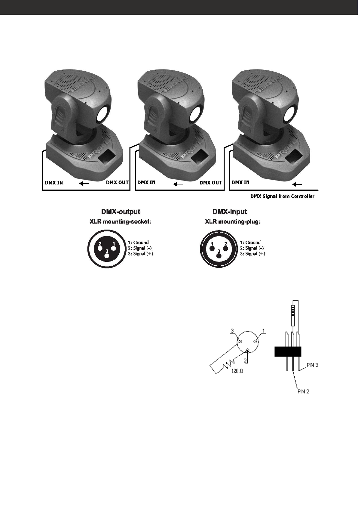
SCHEMA DI CONNESSIONE DMX
Per costruire una catena DMX, connettere
il cavo DMX dalla porta DMX OUTPUT alla
porta DMX IN del proiettore successivo.
Seguire la stessa procedura per gli
eventuali proiettori posti a valle della
catena.
Il terminatore DMX è semplicemente un
connettore XLR con collegato ad esso una
resistenza da 120Ω (Ohm) tra i piedini 2 e
3. La resistenza viene innestata nella presa
del DMX OUT dell’ultimo proiettore della
catena.
9
Page 10

Connessione di rete
Connessione di rete
Connessione di reteConnessione di rete
Connettere l’unità alla tensione di rete utilizzando il cavo contenuto nella
scatola.
L’occupazione dei cavi è la seguente:
Colore cavo Descrizione Simbolo
Marrone Fase L
Blue Neutro N
Giallo/verde Terra GND
La terra deve essere connessa.
PERSONALITY
Canale 1
Canale 1 –––– Otturatore
Canale 1 Canale 1
0-31 chiuso
32-63 aperto
64-95 effetto strobo da lento a veloce
Otturatore
Otturatore Otturatore
96-127 aperto
128-143 apertura pulsata da lenta a veloce
144-159 chiusura pulsata da lenta a veloce
160-191 aperto
192-223 macro
224-255 aperto
Canale 2
Canale 2 –––– Dimmer
Canale 2 Canale 2
0-255 Regolazione del dimmer da 0 a 100 %
Canale
Canale 3
CanaleCanale
0 Aperto
18 magenta
35 giallo
53 arancio
71 verde
89 rosso
107 blu
124 viola
Dimmer
Dimmer Dimmer
3 –––– Ruota c
Ruota colore
3 3
Ruota c Ruota c
olore
olore olore
128-191 Effetto rainbow in senso orario
192-255 Effetto rainbow in senso antiorario
10
Page 11

Canale 4
Canale 4 –––– Ruota gobo
Canale 4 Canale 4
Ruota gobo
Ruota gobo Ruota gobo
0 no gobo
8 gobo 1
16 gobo 2
24 gobo 3
32 gobo 4
40 gobo 5
48 gobo 6
56 gobo 7
64 shake no gobo
84 shake gobo 1
104 shake gobo 2
124 shake gobo 3
144 shake gobo 4
164 shake gobo 5
184 shake gobo 6
204 shake gobo 7
224-255 rainbow gobo
Canale
Canale 5555 –––– Rotazione gobo
Canale Canale
Rotazione gobo
Rotazione gobo Rotazione gobo
0-127 Index
128-191 Rotazione gobo in senso orario
192-255 Rotazione gobo in senso antiorario
Canale
Canale 6
CanaleCanale
6 –––– Focus
Focus
6 6
Focus Focus
0-255 Regolazione della messa a fuoco
Canale
Canale 7777 –––– Movimento orizzontale (Pan)
Canale Canale
Movimento orizzontale (Pan)
Movimento orizzontale (Pan) Movimento orizzontale (Pan)
Muovere lo slider sulla centralina corrispondente al canale 7 della testa
mobile per controllare il movimento orizzontale della testa.
Canale
Canale 8888 –––– Movimento verticale (Tilt)
Canale Canale
Movimento verticale (Tilt)
Movimento verticale (Tilt) Movimento verticale (Tilt)
Muovere lo slider sulla centralina corrispondente al canale 8 della testa
mobile per controllare il movimento verticale della testa.
Canale 9
Canale 9 ---- Movimento fine orizzontale (Pan Fine)
Canale 9 Canale 9
Movimento fine orizzontale (Pan Fine)
Movimento fine orizzontale (Pan Fine)Movimento fine orizzontale (Pan Fine)
Muovere lo slider sulla centralina corrispondente al canale 9 della testa
mobile per controllare il movimento fine orizzontale della testa.
Canale 10
Canale 10 –––– Movimento fine verticale (Tilt Fine)
Canale 10 Canale 10
Movimento fine verticale (Tilt Fine)
Movimento fine verticale (Tilt Fine) Movimento fine verticale (Tilt Fine)
Muovere lo slider sulla centralina corrispondente al canale 10 della testa
mobile per controllare il movimento fine verticale della testa.
Canale 11
Canale 11 –––– Velocità di movimento Pan e Tilt
Canale 11 Canale 11
Velocità di movimento Pan e Tilt
Velocità di movimento Pan e Tilt Velocità di movimento Pan e Tilt
0-255 Regoalzione delle velocità di movimento orizzontale e verticale.
11
Page 12

MODALITÀ 8 CANALI
Selezionando la modalità a 8 bit (vedi paragrafo precedente) la testa
mobile perde gli ultimi 3 canali DMX andando così ad occupare un totale
di 8 canali.
MANUTENZIONE
Assicurasi che l’unità sia scollegata dall’alimentazione di rete
prima di eseguire manutenzione.
L’operatore deve prestare attenzione alle norme di sicurezza e solo
personale qualificato può procedere alle operazioni di manutenzione
dell’apparecchio.
La manutenzione va fatta regolarmente almeno una volta l’anno e si
consiglia di usare solo un panno asciutto per la pulizia.
Non usare solventi od altre sostanza contenenti alcol.
Le ventole di raffreddamento devono essere pulite mensilmente.
I filtri dicroici, i gobo e le lenti devono essere puliti con un panno morbido.
Le parti interne vanno pulite utilizzando aria compressa.
Lubrificare periodicamente (ogni 6 mesi) gli ingranaggi della ruota colori e
della ruota gobo.
Sostituzione del fusibile
Sostituzione del fusibile
Sostituzione del fusibileSostituzione del fusibile
Nella sostituzione del fusibile assicurarsi di utilizzare un fusibile con le
stesse specifiche riportate dall’apparecchio e su questo manuale.
- Aprire il porta fusibile posto sul pannello posteriore dell’apparecchio
- Rimuovere il vecchio fusibile danneggiato
- Installare il nuovo fusibile
- Richiudere il porta fusibile
Sostituire anche il cavo di alimentazione se lo stesso risulta danneggiato.
12
Page 13

SPECIFICHE TECNICHE
Alimentazione: 230V AC, 50 Hz o 120V AC, 60Hz
Potenza assorbita: 280 W
Lampada: Master Colour 150W GY12
Numero canali DMX : 11 (modalità 16bit)
8 (modalità 8bit)
DMX 512: 3-pin XLR
Numero di colori 7 + bianco
Numero di gobo: 7 gobo intercambiabili
Dimensioni (LxPxA): 300 x 340 x 500 mm
Peso: Circa 12 kg
Temperatura ambiente: 0 - 45°C
Massima temperatura delle
superfici esterne durante il
funzionamento:
Minima distanza dale superfici
illuminate
95 ° C
0.5 m
Fusibile: 1.5 A, 250 V
Grado proetezione: IP20
13
Page 14
TABLE OF CONTENTS
TABLE OF CONTENTS
TABLE OF CONTENTSTABLE OF CONTENTS
SAFETY RULES.......................................................................................................................................................... 15
NOTICE INFORMATION ........................................................................................................................................ 15
SAFETY INSTRUCTIONS........................................................................................................................................ 16
OPERATING DETERMINATIONS ........................................................................................................................17
FEATURES.................................................................................................................................................................. 18
INSTALLATION......................................................................................................................................................... 18
CONTROL BOARD/LCD MENU .......................................................................................................................... 19
DMX-512 CONNECTION / CONNECTION BETWEEN FIXTURES............................................................. 21
PERSONALITY........................................................................................................................................................... 22
8 CHANNEL MODE................................................................................................................................................. 24
CLEANING AND MAINTENANCE....................................................................................................................... 24
TECHNICAL SPECIFICATIONS.............................................................................................................................25
The specifications related in this manual are subject to modifications
without any advance notice
Rev. 00 – 25/2008
Page 15

Please note that due to continuous product development, the
specifications are subject to change without notice. Whilst every care is
taken in the preparation of this manual Proel SpA reserves the right to
change specifications in the course of the product improvement. The
publishers cannot be held responsible for the accuracy of the information
herein, or any consequence arising from them.
SAFETY RULES
In order to use the PLML150E more availably and effectively, please read
and take care of this manual. The following rules give important
information regarding safety during use and maintenance.
- This product is not intended for domestic utilization.
- Keep the unit dry, do not expose it to water or high levels of humid. And
never operate the unit with wetted hands.
- Do not dismantle or modify the product non-authorizedly.
- If any liquid is spilled on or in the unit, disconnect the power supply to
the product immediately.
- Do not open the unit --- there is no user serviceable parts inside.
- Handle this product carefully, any strong shocks or vibration may result
in malfunction.
NOTICE INFORMATION
- Before operating, please make sure that the unit has not suffered any
damage during transportation. Should any damage have occurred,
please do not use it and contact the local dealer immediately.
- We won’t be responsible for any resulting damage due to your
inobservance or improper operation on the unit. Never allow nonauthorized and unqualified personnel with any kind of intervention to
the product.
- Specifications are subject to change without notice. For further
information or latest software updating, please visit our web-site:
www.proelgroup.com
www.proelgroup.com
www.proelgroup.comwww.proelgroup.com
Copyrig
Copyright notice:
CopyrigCopyrig
or translated into any language in any form without authorized
permission.
ht notice: no part of this product can be reproduced, transmitted,
ht notice:ht notice:
15
Page 16

SAFETY INSTRUCTIONS
This device has left our premises in absolutely perfect condition. In order
to maintain this condition and to ensure a safe operation, it is absolutely
necessary for the user to follow the safety instructions and warning notes
written in this user manual.
)))) Important:
Damages caused by the disregard of this user manual are not subject to
warranty.
Do not use this product in environment where the temperature is under
0°C or over 45°C. The arising condensation water might damage your
device.
Please make sure that there are no obvious transport damages. If you
notice any damages on the product, do not connect the device to the
mains and immediately consult your dealer.
This device falls under protection-class I. The power plug must only be
plugged into a protection class I outlet.
Assure that the voltage and frequency values are suitable with the same
data printed on the device.
Never let the power-cord come into contact with other cables. Handle the
power-cord and all connections with the mains with particular caution.
Never touch them with wet hands, as this could lead to mortal electrical
shock.
Important:
Important:Important:
Never modify, bend, strain mechanically, put pressure on, pull or heat up
the power cord.
Never pull out the plug by tugging the power-cord.
All warnings concerning the power cords are also valid for possible
extension cords.
Always disconnect from the mains, when the device is not in use or before
cleaning it.
If the power plug or the device is dusty, the device must be taken out of
operation. Proceed to cleaning by following the relative paragraph.
There must never enter any liquid into power outlets, extension cords or
any holes in the housing of the device. If you suppose that also a minimal
amount of liquid may have entered the device, it must immediately be
disconnected. This is also valid, if the device was exposed to high
humidity.
There must never be any objects entering into the device. This is especially
valid for metal parts. If any metal parts like staples or coarse metal chips
16
Page 17
enter into the device, the device must be taken out of operation and
disconnected immediately.
Caution: During the operation, the housing becomes very hot.
Do not switch the device on and off in short intervals as this would reduce
the lamp’s life.
HEALTH HAZARD!
Never look directly into the light source in order to avoid
injures to eyes.
Never leave this device running unattended.
OPERATING DETERMINATIONS
This PLML150E is a lighting effect for creating decorative effects. This
product is only allowed to be operated with an alternating voltage of
230V, 50Hz (120V , 60Hz on request) and was designed for indoor use only.
Do not shake the device. Avoid brute force when installing or operating
the device.
When choosing the installation-spot, please make sure that the device is
not exposed to extreme heat, moisture or dust. Moisture or very high
humidity can reduce the insulation and lead to mortal electrical shocks.
Keep the device off form smoke, dust or steam.
The relative humidity must not exceed 50 % with an ambient temperature
of 45° C.
The symbol determines the minimum distance from lighted
objects. The minimum distance between light-output and the illuminated
surface must be more than 0.5 meters.
In order to safeguard sufficient ventilation, leave 10 cm of free space
around the device.
Always fix the fixture with an appropriate safety-rope.
Use the original packaging if the device is to be transported. Never
remove the serial barcode from the carton box as this would make the
guarantee void.
Consider that unauthorized modifications on the device are forbidden due
to safety reasons!
17
Page 18
FEATURES
- 8 channels or 11 channels mode selectable
- 7 different dichroic colour-filters and white
- Rainbow-effect with adjustable speed in both directions
- Gobo-wheel with 7 interchangeable gobos + open
- Shake effect
- Motorized focus
- 150 W discharge lamp
INSTALLATION
Installing/Rep
Installing/Replacing the lamp
Installing/RepInstalling/Rep
The lamp must only be changed when wearing appropriate protective
lacing the lamp
lacing the lamp lacing the lamp
DANGER TO LIFE! UNPLUG FROM MAINS BEFORE OPERATING!
Only install the lamp with the device switched off!
clothing (protection glasses, protection gloves, helmet with sight, leather
apron).
CAUTION! The lamp has to be replaced when it is damaged or
deformed.
The lamp life given by the manufacturer must NEVER be exceeded.
During the operation, the lamp reaches temperatures of up to 600° C.
After switching off the appliance, allow the lamp to cool down (approx. 10
minutes).
Do not install any lamp with different specifics from that one indicates in
this manual.
Procedure:
Procedure:
Procedure: Procedure:
- Step 1: Unscrew the four screws on the rear part of the head;
- Step 2: Carefully remove the lamp holder;
- Step 3: If replacing the lamp, remove the old lamp from the lamp holder;
- Step 4: Insert the new Master Colour CDM-SA/T 150W/942 lamp;
- Step 5: Close the cover;
- Step 6: Tighten the four housing screws.
18
Page 19

INSTRUCTUION
CONTROL BOARD/LCD MENU
DMX ad
DMX address:
DMX adDMX ad
DISPLAY DESCRIPTION
DMX Addr Press and rotate the knob to select the DMX value for
Pan/Tilt reverse:
Pan/Tilt reverse:
Pan/Tilt reverse: Pan/Tilt reverse:
DISPLAY DESCRIPTION
PAN rev Pan Reverse. Press and rotate the knob until selecting PAN
dress:
dress: dress:
address the fixture.
Press the rotating knob to fix the value, then select Exit to
confirm and exit.
rev. Press the knob and select yes to invert the PAN
position. Select no to have the PAN in normal mode.
Press the rotating knob to fix the value, then select Exit to
confirm and exit.
TILT rev Pan Reverse. Press and rotate the knob until selecting TITL
rev. Press the knob and select yes to invert the TILT
position. Select no to have the TILT in normal mode.
Press the rotating knob to fix the value, then select Exit to
confirm and exit.
8bit
8bit ---- 16bit mode
8bit 8bit
DISPLAY DESCRIPTION
RSLTN Select 8bit to have the control of the fixture by means of 8
16bit mode
16bit mode 16bit mode
channels. Select 16bit to have the control of the fixture by
means of 11 channels.
Press the rotating knob to fix the value, then select Exit to
confirm and exit.
19
Page 20

Adjustme
Adjustment
AdjustmeAdjustme
DISPLAY DESCRIPTION
ADJUST Press and rotate the knob to select the motor of which to
Restoring the default setting
Restoring the default setting
Restoring the default settingRestoring the default setting
DISPLAY DESCRIPTION
DEFAULT Press and rotate the knob to select Default from the menu.
Reset
Reset
ResetReset
nt
ntnt
calibrate the position.
PAN, TILT, COLOR, GOBO are respectivelly the motors of
PAN, TILT, Colour Wheel and Gobo wheel. Once you have
selected the value, press the rotating knob to fix the value,
then select Exit to confirm and exit.
Select yes to restore the original setting.
DISPLAY DESCRIPTION
RESET Press and rotate the knob to select Reset from the menu.
Select yes to enable the reset.
After switching on, the moving head will automatically detect whether
DMX 512 data is received or not. No data receiving can occur if:
- the 3 PIN XLR plug (cable with DMX signal from controller) is not
connected with the input of the moving head.
- the controller is switched off or defective, if the cable or connector is
defective or the signal wires are swap in the input connector.
- noise occurrence in the signal cable. Try to insert the XLR termination
plug (with 120 Ohm) in the last lighting in the link in order to ensure
proper transmission on the DMX data link.
20
Page 21
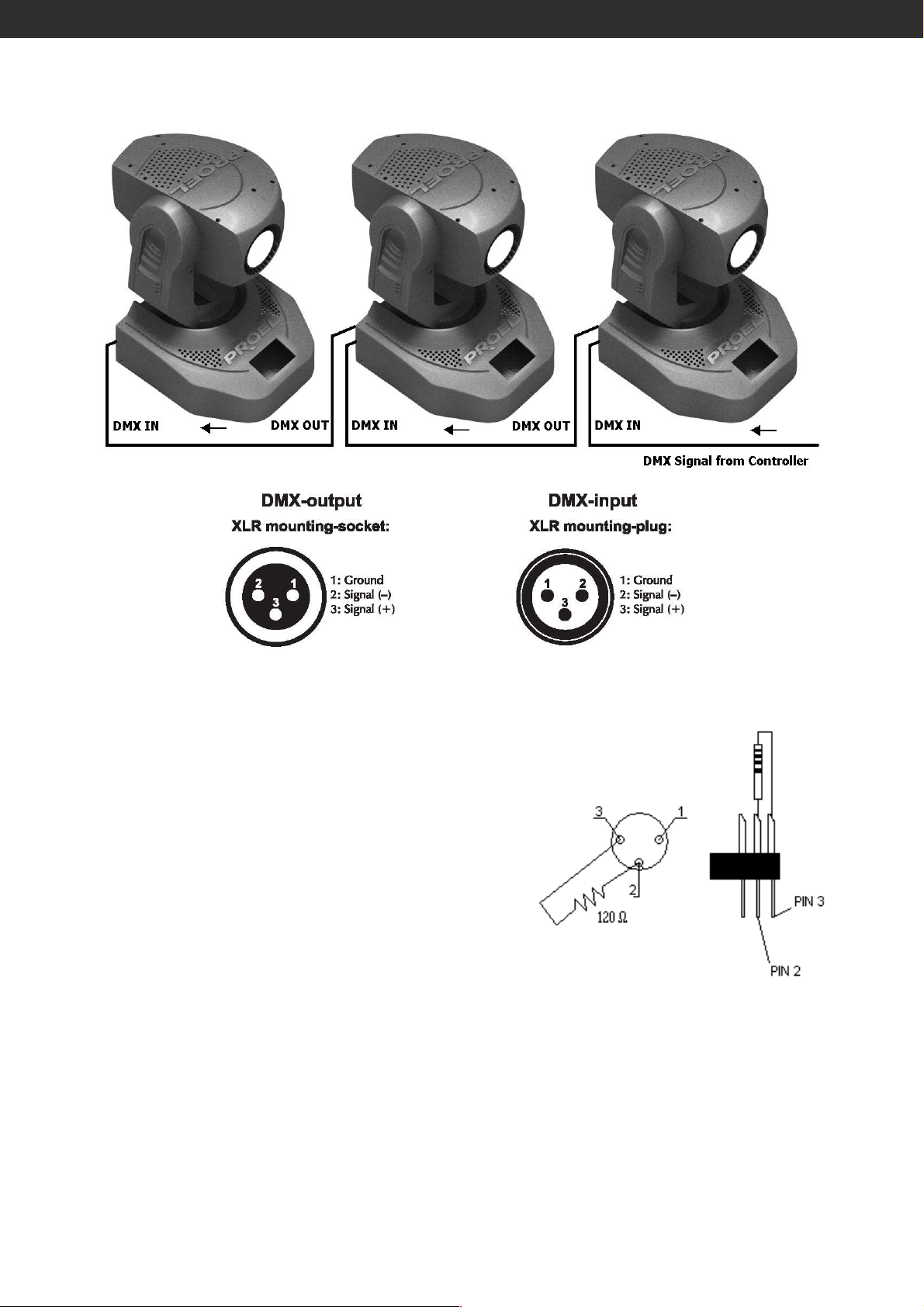
DMX-512 CONNECTION / CONNECTION BETWEEN FIXTURES
If you are using controllers with this
occupation, you can connect the DMXoutput of the controller directly with the
DMX-input of the first fixture in the DMXchain. The DMX terminator is simply an
XLR connector with a 120Ω (Ohm) resistor
connected across pins 2 and 3, which is
then plugged into the DMX OUT socket on
the last projector in the chain.
21
Page 22

Connection with the mains
Connection with the mains
Connection with the mains Connection with the mains
Connect the device to the mains with the enclosed power supply cable.
The occupation of the connection-cables is as follows:
Cable Pin International
Brown Live L
Blue Neutral N
Yellow/Green Ground GND
The earth must be connected!
PERSONALITY
Channel 1
Channel 1 –––– Shutter
Channel 1 Channel 1
0-31 close
32-63 open
64-95 strobe effect from slow to fast
96-127 open
Shutter
Shutter Shutter
128-144 pulse opening from slow to fast
144-159 pulse closing from slow to fast
160-191 open
192-223 macro
224-255 open
Channel 2
Channel 2 –––– Dimmer
Channel 2 Channel 2
0-255 dimmer adjustment from 0 to 100 %
Channel
Channel 3333 –––– Colour wheel
Channel Channel
0 open
19 magenta
35 yellow
54 orange
71 green
89 red
107 blue
125 purple
128-191 clockwise rainbow effect
Dimmer
Dimmer Dimmer
Colour wheel
Colour wheel Colour wheel
192-255 counter clockwise rainbow effect
22
Page 23

Channel 4
Channel 4 –––– Gobo wheel
Channel 4Channel 4
Gobo wheel
Gobo wheel Gobo wheel
0 no gobo
8 gobo 1
16 gobo 2
24 gobo 3
32 gobo 4
40 gobo 5
48 gobo 6
56 gobo 7
64 shake no gobo
84 shake gobo 1
104 shake gobo 2
124 shake gobo 3
144 shake gobo 4
164 shake gobo 5
184 shake gobo 6
204 shake gobo 7
224-255 rainbow gobo
Channel
Channel 5555 ––––Gobo rotation
ChannelChannel
Gobo rotation
Gobo rotationGobo rotation
0-127 index
128-191 clockwise gobo rotation
192-255 counter clockwise gobo rotation
Channel
Channel 6666 –––– Focus
Channel Channel
Focus
Focus Focus
0-256 focus adjustment
Channel
Channel 7777 –––– Horizontal movement (Pan)
Channel Channel
Move the slider relative to 7
head horizontally (PAN).
Channel
Channel 8888 –––– Vertical movement (Tilt)
Channel Channel
Move the slider relative to 8
Horizontal movement (Pan)
Horizontal movement (Pan) Horizontal movement (Pan)
th
channel of the fixture in order to move the
Vertical movement (Tilt)
Vertical movement (Tilt) Vertical movement (Tilt)
th
channel of the fixture in order to move the
head vertically (TILT).
Channel
Channel 9
Channel Channel
Move the slider relative to 9
9 –––– Horizontal
Horizontal fine movement (Pan Fine)
9 9
Horizontal Horizontal
fine movement (Pan Fine)
fine movement (Pan Fine)fine movement (Pan Fine)
th
channel of the fixture in order to control the
horizontal fine movement of the head (PAN fine).
Channel 10
Channel 10 –––– Vertical
Channel 10 Channel 10
Vertical fine movement (Tilt Fine)
Vertical Vertical
fine movement (Tilt Fine)
fine movement (Tilt Fine)fine movement (Tilt Fine)
Move the slider relative to 10th channel of the fixture in order to control
the vertical fine movement of the head (PAN fine).
Chan
Channel
ChanChan
nel 11
11 –––– Speed of Pan & Tilt movements
nel nel
Speed of Pan & Tilt movements
11 11
Speed of Pan & Tilt movements Speed of Pan & Tilt movements
0-255 Adjust the speed of the Pan and Tilt movemnts.
23
Page 24

8 CHANNEL MODE
Selicting the 8 bit mode (see the paragraph above), the moving head loses
the last 3 DMX channels and it will have totally 8 channels.
CLEANING AND MAINTENANCE
DANGER OF LIFE!
Disconnect from mains before starting maintenance
operation!
Maintenance and service operations are only to be carried out by
authorized persons once a year.
We recommend a frequent cleaning of the device. Please use a moist, lintfree cloth. Never use alcohol or solvents.
The cooling-fans should be cleaned monthly. The interior of the fixture
should be cleaned at least annually using a vacuum-cleaner or an air-jet.
The dichroic colour-filters, the gobo-wheel and the internal lenses should
be cleaned monthly. To ensure a proper function of the gobo-wheel, we
recommend lubrication in six month intervals.
Replacing the fuse
Replacing the fuse
Replacing the fuse Replacing the fuse
If the fine-wire fuse of the device fuses, only replace the fuse by a fuse of
same type and rating.
- Step 1: Open the fuse holder on the rear panel with a fitting screw
driver.
- Step 2: Remove the old fuse from the fuse holder.
- Step 3: Install the new fuse in the fuse holder.
- Step 4: Replace the fuse holder in the housing.
If the power supply cable of this device becomes damaged, it has to be
replaced by a special power supply cable available at your dealer.
24
Page 25

TECHNICAL SPECIFICATIONS
Power supply: 230V AC, 50 Hz or 120V AC, 60 Hz
Power consumption: 280 W
Lamp: Master Colour 150W GY12
DMX-control-channels: 11 (16bit mode)
8 (8bit mode)
DMX-512-connection: 3-pin XLR
Number of colours: 7 dichroic color + white
Number of gobos: 7 interchangeable gobos + white
Dimensions (LxWxH): 300 x 340 x 500 mm
Weight: Approx. 12kg
Ambient temperature: 0 - 45°C
Maximum housing
temperature (steady state):
Min.distance to lighted object: 0.5 m
Fuse: 1.5 A, 250 V
Housing: IP20
95 ° C
25
Page 26

NOTE
NOTE
NOTENOTE
26
Page 27

Page 28

28
 Loading...