

2
MOVING HEAD 575 WASH
PERFORMANCE
PLML575EPS
- C
2

INDICE:
ATTENZIONE………………………………………………………………… p. 3
INTRODUZIONE…………………………………………………………….. p. 3
CARATTERISTICHE………………………………………………………… p. 3
NORME DI SICUREZZA……………………………………………………. p. 5
CONDIZIONI OPERATIVE………………………………………………….. p. 6
INSTALLAZIONE…………………………………………………………….. p. 7
Installazione / sostituzione lampada…………………………………. p. 7
Regolazione della lampada…………………………………………… p. 8
Montaggio……………………………………………………………….. p. 9
Connessione ad una centralina DMX /
connessione fra apparecchi…………………………………………… p. 11
Connessione alla rete di alimentazione……………………………… p. 12
FUNZIONI DEL CONTROLLO CANALI – PROTOCOLLO 16 BIT…….. p. 12
FUNZIONI DEL CONTROLLO CANALI – PROTOCOLLO 8 BIT…..….. p. 15
INDIRIZZAMENTO…………………………………………………………… p. 15
CONTROLLI………………………………………………………………….. p. 16
PANNELLO DI CONTROLLO……………………………………………… p. 17
MESSAGGI DI ERRORE…………………………………………………… p. 25
CARATTERISTICHE TECNICHE..………………………………………… p. 27
PULIZIA E MANUTENZIONE………………………………………………. p. 30
CLEANING AND MAINTENANCE
CAUTION: Disconnect from mains before starting maintenance operation!
It is absolutely essential that the fixture is kept clean and that dust, dirt and smoke-fluid
residues must not build up on or within the fixture. Otherwise, the fixture‘s light-output will
be significantly reduced. Regular cleaning will not only ensure the maximum light-output,
but will also allow the fixture to function reliably throughout its life.
Please use a moist, lint-free cloth. Never use alcohol or solvents!
CAUTION: The lens has to be replaced when it is obviously damaged, so that its function
is impaired, e. g. due to cracks or deep scratches!
The Fresnel lens will require weekly cleaning as smoke-fluid tends to building up
residues, reducing the light-output very quickly. The cooling-fans should be cleaned
monthly.
The interior of the fixture should be cleaned at least annually using a vacuum-cleaner or
an air-jet. The dichroic colour-filters should be cleaned monthly.
There are no serviceable parts inside the device except for the lamp and the fuse.
Maintenance and service operations are only to be carried out by authorized dealers.
REPLACING THE FUSE
Only replace the fuse by a fuse of same type and rating.
Before replacing the fuse, unplug mains lead.
PROCEDURE:
1. Unscrew the fuse holder on the rear panel with a fitting screw driver from the
housing
2. Remove the old fuse from the fuse holder.
3. Install the new fuse in the fuse holder.
4. Replace the fuse holder in the housing and fix it.
Should you need any spare parts, please use genuine parts.
If the power supply cable of this device becomes damaged, it has to be replaced by
authorized dealers.
Should you have further questions, please contact your dealer.
2
59
Temperatures
Maximum ambient temperature 40° C
Maximum housing temperature 80° C
Dimensions and weight
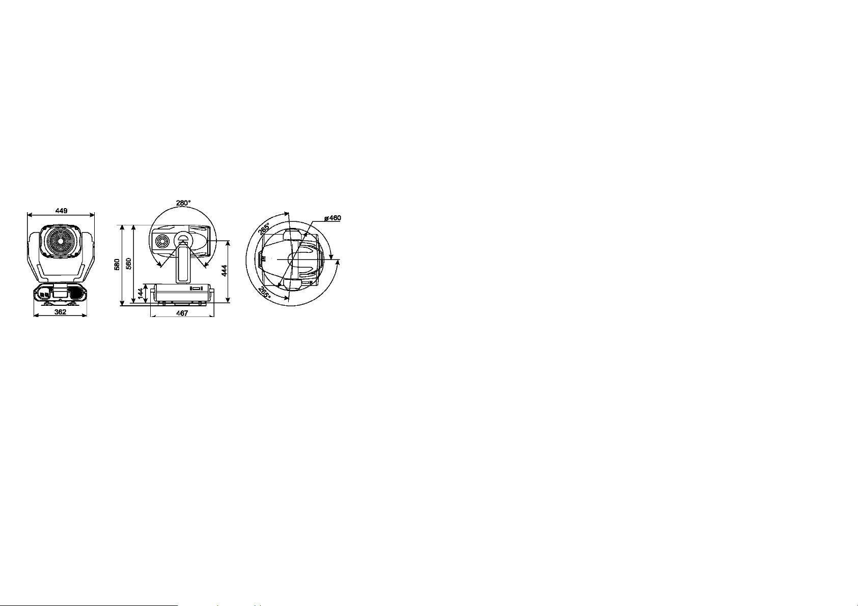
Length of base (including handles): 467 mm
Width of yoke: 449 mm
Height (head horizontal): 580 mm
Weight (net): 33 kg
Shipping weight: 38 kg
ATTENZIONE !
- Tenere questo apparecchio lontano da pioggia e umidità
- Scollegare il cavo dalla rete di alimentazione prima di aprire il coperchio
PER LA VOSTRA SICUREZZA, LEGGERE ATTENTAMENTE QUESTO MANUALE
PRIMA DI ACCENDERE L’APPARECCHIO PER LA PRIMA VOLTA
Chiunque si occupi dell’installazione, uso e manutenzione di questo apparecchio deve:
- essere una persona qualificata
- seguire le istruzioni riportate sul presente manuale
INTRODUZIONE
Grazie per aver scelto il testamobile PLML575E. Vi renderete presto conto di aver
acquistato un apparecchio potente e versatile.
Togliere dall’imballo il testamobile PLML575E.
Prima di accenderlo per la prima volta, sinceratevi che non vi siano danni provocati dal
trasporto. Se ve ne fossero, contattate il vostro rivenditore di fiducia e non utilizzate
questo apparecchio.
CARATTERISTICHE
Miscelazione colori CMY , ruota colori motorizzata con 4 differenti filtri dicroici più filtri di
correzione 3200K, 6000K e filtri UV.
Effetto rainbow. Macro per la combinazione fra la ruota colori e il CMY. Filtro frost.
Effetto Beam Shaper: fascio largo e piatto che può essere ruotato gradualmente di 180º.
Unità shutter/dimmer combinata che permette un dimmer omogeneo ed un effetto strobo
con 1-10 flash al secondo.
Ventole silenziose per il raffreddamento con velocità controllabile a distanza.
Costruzione modulare dell’apparecchio. Design elegante. 2 maniglie per il trasporto.
Indirizzamento, funzioni speciali per il settaggio effetti e calibrazione, attraverso il
pannello di controllo con display a led con 4 caratteri. Lettura del tempo di utilizzo
dell’apparecchio e della lampada, temperatura, valore del DMX.
Analizzatori per semplici messaggi di errore. Accensione e spegnimento a distanza della
lampada. Possibilità di sequenze demo.
Effetto strobo preprogrammato o random, ed effetto pulsazione del dimmer. Possibilità di
black out mentre la testa è in movimento. Velocità del pan/tilt controllabile a distanza per
una facile programmazione. Funzione reset a distanza. Ventole di raffreddamento
silenziose; velocità delle ventole regolabile dal DMX. DMX con 16 canali – movimento di
pan/tilt con una risoluzione di 16 bit. DMX con 14 canali, risoluzione del movimento di
pan/tilt 8 bit. Ampiezza massima del movimento del pan 530°. Ampiezza massima del
movimento del tilt 280°. Risoluzione del movimento 8/16 bit. Correzione automatica della
posizione di pan e tilt (encoder). Specchi parabolici ad alta efficienza luminosa. Lenti anti
riflessione. 13 motori passo passo di elevata qualità per movimenti fini. Fusibile termico
per auto spegnimento. Lampada HSR/MSR 575. Controllo attraverso standard DMX.
58
3
1
2
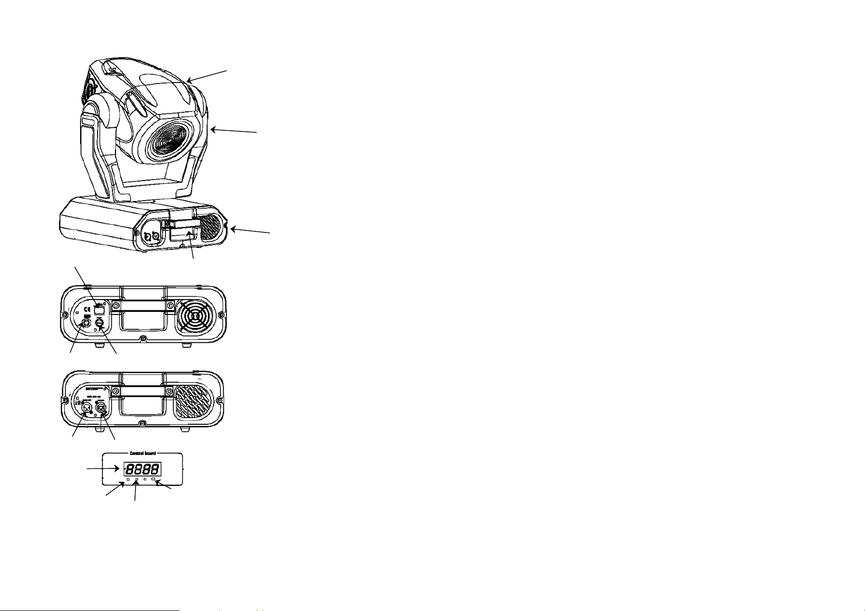
1 - testa del proiettore
2 - bracci
3 - base
4 - maniglia
3
5
8
10
9
11
12
13
4
5 - pulsante accensione
6 - portafusibile
7 - cavo potenza
8 - DMX input
9 - DMX output
10 - display
11 - enter
12 - mode
13 - Up/down
Dimmer
Smooth dimmer from 0 - 100 %
Motor
13 high quality stepping-motors controlled by microprocessors
Electronics
Digital serial input DMX-512
16 control-channels (full 16 bit protocol):
Channel 1: Horizontal movement 8 bit
Channel 2: Fine Horizontal mirror-movement 16 bit
Channel 3: Vertical movement 8 bit
Channel 4: Fine Vertical mirror-movement 16 bit
Channel 5: Pan/Tilt speed
Channel 6: Fan speed, On/Off lamp, reset
Channel 7: Colour-wheel
Channel 8: Cyan
Channel 9: Magenta
Channel 10: Yellow
Channel 11: Speed of CMY and dimmer
Channel 12: Colour macros - CMY and colour-wheel
Channel 13: Beam-effect
Channel 14: Zoom
Channel 15: Shutter, Strobe
Channel 16: Dimmer
Pan/Tilt
Pan movement range 530°
Tilt movement range 280°
8/16 bit movement resolution
Automatic Pan / Tilt position correction
Maximum PAN-movement 530° in 3 s
Maximum TILT-movement 280° in 2.2 s
Rigging
Stands directly on the floor
Mounts horizontally or vertically with 2 clamps
2 truss orientation
Safety chain/cord eye bolt
4
57
TECHNICAL SPECIFICATIONS
Power supply 230V / 50Hz
(117V / 60Hz USA)
Power consumption 800W
DMX channels 14 / 16 (16 bit)
DMX connector 3-pole XLR
Length 475 mm
Width 465 mm
Height 515 mm
Net weight 33 kg
Maximum ambient temperature 40 °C
Maximum housing temperature 90 °C
Minimum distance from flammable surfaces 1 m
Minimum distance from illuminated surfaces 1 m
Fuse F10A 250V
Specification subject to changes without notice
Lamp
HSR / MSR 575
Optical System
High luminous-efficiency parabolic mirror
Motorized Fresnel lens
Anti reflection lens
Colours
CMY colour-mixture
4 interchangeable dichroic-filters plus white, correction-filters 3200K, 6000 K, UV-filter
Colour-wheel with variable rotation speed
Strobe
Strobe effect with variable speed (1 - 10 flashes per second)
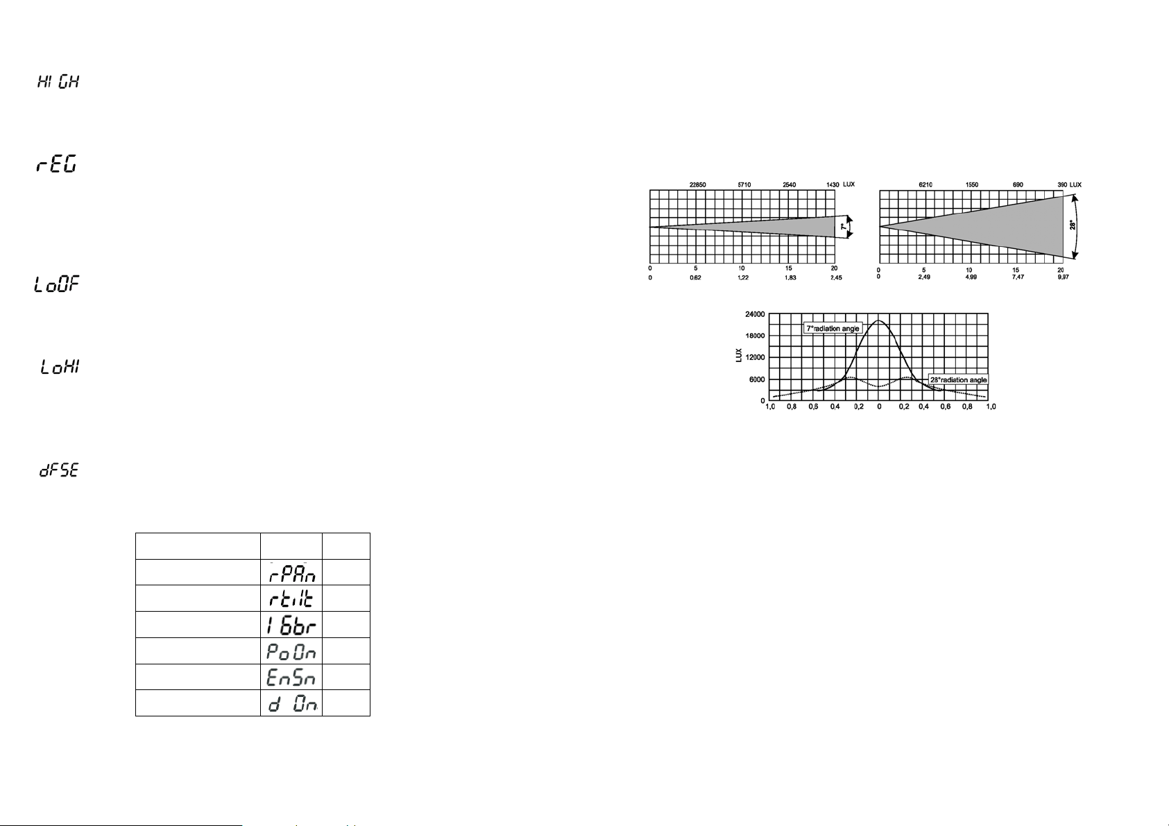
Zoom
Remotely controllable via DMX
Motorized zoom adjustable between 7° and 28°
NORME DI SICUREZZA
ATTENZIONE: prestare particolare attenzione alle operazioni da effettuare. Con l’alta
tensione potreste subire pericolosi shock elettrici toccando i cavi.
Questo apparecchio ha lasciato i nostri stabilimenti in condizioni assolutamente perfette.
Per mantenerle tali e per effettuare operazioni in sicurezza, è importante che l’utente
segua le istruzioni di sicurezza e gli avvertimenti riportati in questo manuale utente.
IMPORTANTE: danni provocati dalla noncuranza di questo manuale, non sono soggetti
a garanzia.
Se l’apparecchio è stato esposto a grandi variazioni di temperatura (per es. dopo il
trasporto), non accenderlo immediatamente. La condensa che si forma potrebbe
danneggiare il Vostro apparecchio. Lasciare spento l’apparecchio fin quando non abbia
raggiunto la temperatura ambiente.
Questo apparecchio appartiene alla CLASSE DI PROTEZIONE I, pertanto la spina di
alimentazione va collegata soltanto a prese che prevedono la protezione di classe I
(collegamento a massa).
Non lasciare il cavo di alimentazione a contatto con altri cavi. Maneggiare il cavo di
alimentazione e tutte le connessioni con la rete principale, prestando particolare
attenzione.
Assicuratevi che la tensione a disposizione non sia superiore a quella specificata sul
pannello posteriore.
Assicurarsi che il cavo di alimentazione non sia deformato o danneggiato da oggetti
taglienti. Controllare periodicamente lo stato dell’apparecchio e del cavo di
alimentazione.
Disconnettere sempre l’apparecchio dalla rete di alimentazione, quando non usato o
prima di pulirlo. Per scollegare dalla rete il cavo di alimentazione impugnare la spina, mai
tirare il cavo.
Alla prima accensione potrebbe presentarsi un po’ di fumo e un leggero odore di
bruciato. Tutto ciò è normale e ciò non significa necessariamente che l’apparecchio sia
difettoso.
ATTENZIONE: durante il normale funzionamento l’involucro esterno diventa molto caldo.
PERICOLO DI INCENDIO: non installare mai l’apparecchio su una superficie altamente
infiammabile (per es. tappeti)
RISCHI PER LA SALUTE: non guardare mai direttamente all’interno della sorgente di
luce, persone sensibili potrebbero avere uno shock epilettico.
Non accendere e spegnere in ristretti intervalli di tempo perchè ciò riduce il tempo di vita
della lampada considerate che danni causati da modifiche manuali all’apparecchio non
sono soggetti a garanzia.
56
5
Tenere lontano dalla portata dei bambini o di persone non esperte.
CONDIZIONI OPERATIVE
Questo apparecchio è un testamobile wash per creare effetti decorativi. Il prodotto può
funzionare soltanto con alimentazione in corrente alternata 230V – 50Hz (120V 60Hz
USA) ed è destinato al solo uso interno.
Questo apparecchio è indicato per uso professionale ad es. palcoscenici, discoteche,
teatri, ecc.
Tale effetto non è indicato per un uso ininterrotto. Durante i periodi di prolungato non
utilizzo è consigliabile disconnetterlo dall’alimentazione, ciò assicurerà una durata di vita
prolungata senza problemi.
Proteggere l’apparecchio da urti o shock improvvisi, sia in fase di installazione che di
normale funzionamento.
Non accendere mai l’apparecchio senza la lampada.
Non scuotere l’apparecchio. Evitare forzature quando si istalla l’apparecchio o quando si
opera con esso.
Non sollevare mai l’apparecchio dai bracci, in quanto le parti meccaniche potrebbero
subire danni. Per il trasporto, usare le apposite maniglie.
La minima distanza fra il punto di emissione del fascio luminoso e la superficie illuminata
deve essere maggiore di un metro.
Nella scelta del punto di installazione del proiettore, evitare luoghi con temperature
elevate, con elevato tasso di umidità e polvere; evitare zone dove si trovano cablaggi
circostanti. Potreste mettere in pericolo sia la vostra che la sicurezza altrui.
Fissare sempre l’apparecchio con un’adeguata fune di sicurezza. Fissare tale fune
tramite il corretto punto di fissaggio al di sotto della base e non tramite le maniglie di
trasporto.
Mettere in funzione l’apparecchio solo dopo essersi assicurati che la scocca esterna sia
saldamente chiusa e tutte le viti siano correttamente serrate.
La lampada non deve mai essere accesa se le lenti dell’obbiettivo o parti del coperchio
sono state rimosse: la lampada a scarica, infatti, se non adeguatamente protetta, emette
radiazioni ultraviolette dannose per la pelle (ustioni) e per gli occhi (congiuntiviti).
La massima temperatura ambiente raccomandata (T
superata.
ATTENZIONE le lenti devono essere sostituite quando sono danneggiate o risulti
compromessa la loro funzionalità.
= 40 °C) non deve mai essere
a
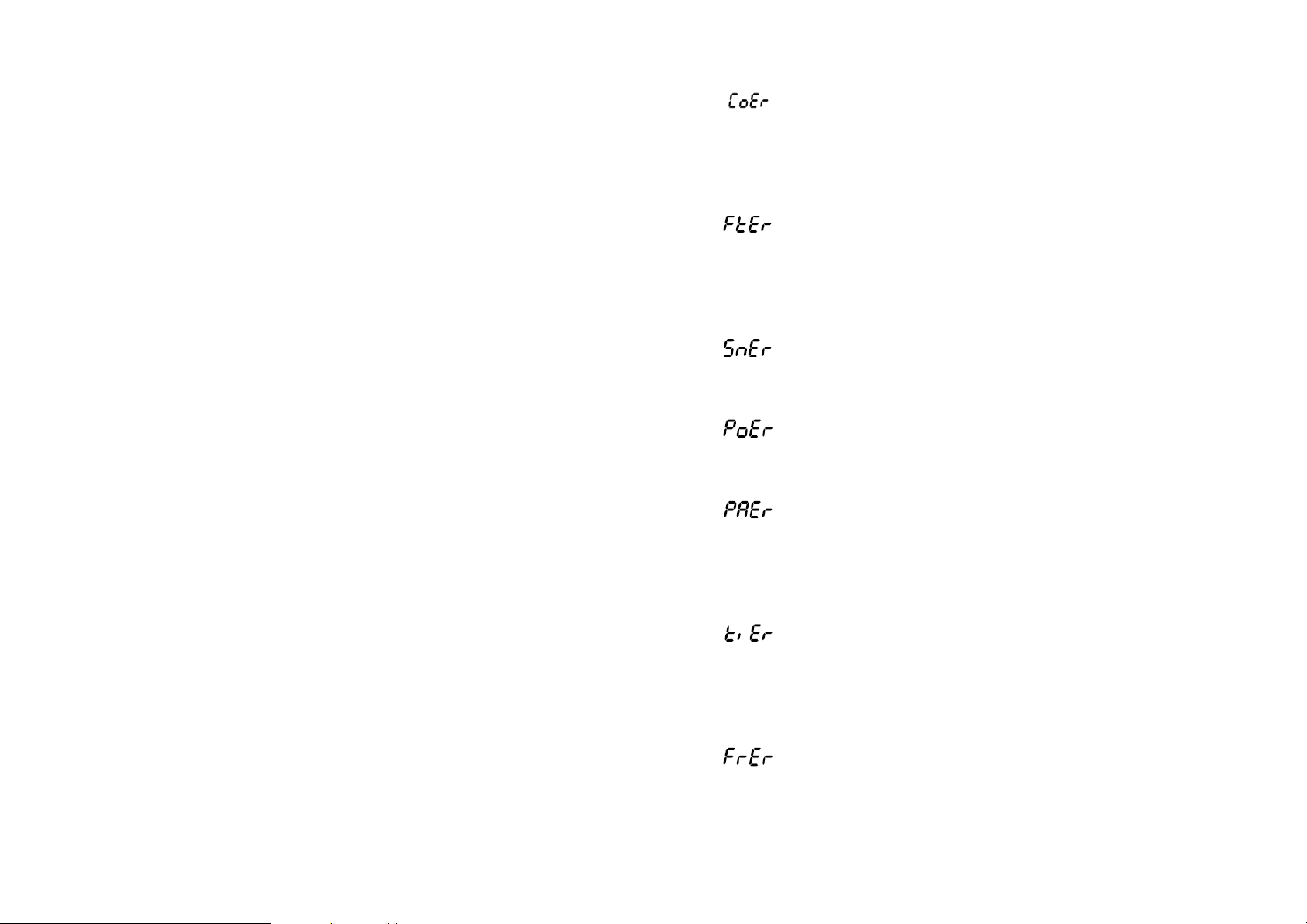
- Color-wheel error
This message will appear after the reset of the fixture if the magnetic-indexing circuit
malfunctions (sensor failed or magnet missing) or the stepping-motor is defective (or its
driver circuit on the main PCB). The color-wheel is not located in the default position
after the reset.
- Overheat
This error message informs you that the fixture was overheating (occured if the ambient
temperature is 40° C or more) and that the relay switched off the lamp. This message will
appear on the display until the temperature will be on a suitable level, then the display
will show the “HEAt” message meaning the lamp is too hot (explanation see above).
- Sensor error
This message appears if the lamp lighting sensor is failed. Please contact your dealer.
- Power error
This message will appear if the fixture was shortly disconnect from the mains.
- Pan error
This message will appear after the reset of the fixture if the yoke’s magnetic indexing
circuit malfunction (sensor failed or magnet missing) or the stepping-motor is defective
(or its driving IC on the main PCB). The yoke is not located in the default position after
the reset.
- Tilt error
This message will appear after the reset of the fixture if the head’s magnetic indexing
circuit malfunctions (sensor failed or magnet missing) or the stepping-motor is defective
(or its driving IC on the main PCB). The head is not located in the default position after
the reset.
- Frequency error
This message will appear if the frequency of the mains is not standard 50 or 60 Hz.
6
55
2. Calibration via the external controller
Press “ENTER” and use the “UP” and “DOWN” keys in order to displa y the following
messages: “Colo”, “EFEC“, - calibration parameters. Select one of them and press
“ENTER”.
Now you can calibrate the colour and effect wheel by your controller. The DMX
calibration protocol is described in the table mentioned below.
DMX
channel
Function
DMX
channel
1 2 3 4 5 6 7 8
Color Effetti - - - - Colours Cyan
Calibration
0-255
Smooth microstep movement
9 10 11 12 13 14 15 16
Magenta Yellow Speed
Standard
protocol
Calibrazioni
0-255
Standard
protocol
- - - - Standard
CMY,dimmer
Standard
protocol
Colours
macros
Standard
protocol
Beam effect Zoom Strobe Dimmer Function
Standard
protocol
Standard
protocol
protocol
Standard
protocol
Standard
protocol
Standard
protocol
After having calibrated required functions press “ENTER” to confirm (or “MODE” to
cancel and return to the menu without reset by the "ArES" function) and use the "ArES"
function in order to write the calibration values to the memory (EEPROM) and to make a
reset in order to check the new settings.
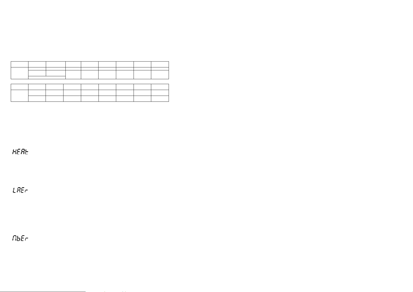
ERROR AND INFORMATION MESSAGES
This message appears if you try to switch on the lamp within 5 minutes after having
switched it off (the lamp is too hot). The message will appear on the display if the lamp
doesn't ignite within 28 seconds. The PLML575E will store this information and
automatically ignite the lamp when the 5 minutes period has expired.
The ignition of the lamp is seven times unsuccessful (the HEAt message appeared six
times before), and the display shows "LAEr", meaning that the lamp could be damaged
or even missed, the fixture is overheating (this can occur if the ambient temperature is
40° C or more) or there could be a failure on the ignitor or ballast.
Please place or replace the lamp, check the ambient temperature or contact your dealer
if the situation was not caused by the lamp.
This message informs you that the main PCB does not communicate correctly with the
Control Board.
- Overheat
- Lamp error
- Mainboard error
Operare con quest’apparecchio solo dopo aver familiarizzato con le sue funzioni. Non
permettere che personale non qualificato possa utilizzare il testamobile: molti danni
infatti sono provocati da un uso improprio.
ATTENZIONE la lampada deve essere sostituita quando è danneggiata.
Usare sempre l’imballo originale per il trasporto.
Modifiche non autorizzate dell’apparecchio, sono vietate per ragioni di sicurezza.
Non rimuovere il codice a barre dall’apparecchio per la garanzia
Se il proiettore dovesse trovarsi ad operare in condizioni differenti da quelle descritte nel
presente manuale, potrebbero verificarsi dei danni; in tal caso la garanzia verrebbe a
decadere, inoltre ogni altra operazione potrebbe provocare cortocircuiti, incendi, scosse
elettriche, esplosioni della lampada, rotture ecc.
INSTALLAZIONE
INSTALLAZIONE / SOSTITUZIONE LAMPADA
PERICOLO: installare la lampada solo quando l’apparecchio è spento e il cavo di
alimentazione è scollegato dalla rete
Utilizzare lampade HSR575/MSR575 o equivalenti, rispettandone le specifiche del
costruttore.
ATTENZIONE: la lampada deve essere sostituita quando è danneggiata o deformata a
causa del calore.
Durante il normale funzionamento, la lampada raggiunge temperature superiori a
Prima di sostituire la lampada, scollegare l’alimentazione e attendere che la stessa
si raffreddi (circa 10 min.)
Durante l’installazione della nuova lampada non toccare il bulbo in vetro con le mani
nude. Seguire le indicazioni del costruttore
Non installare lampade con una potenza maggiore di quella indicata. Queste infatti
generano elevate temperature, che il testamobile non è progettato per sopportare.
Danni provocati da noncuranze di questo tipo causano la decadenza della garanzia
PROCEDIMENTO PER LA SOSTITUZIONE DELLA LAMPADA :
1. Svitare le viti di fissaggio (X, Y, Z) del coperchio del portalampada e rimuoverlo
2. Se bisogna sostituire la lampada, rimuovere la vecchia dal portalampada
3. Inserire la lampada nuova nel portalampada
4. Riposizionare il coperchio del portalampada e riavvitare le viti (X,Y,Z) di fissaggio
5. Regolare la lampada se necessario come descritto più avanti
600 °C.
54
7
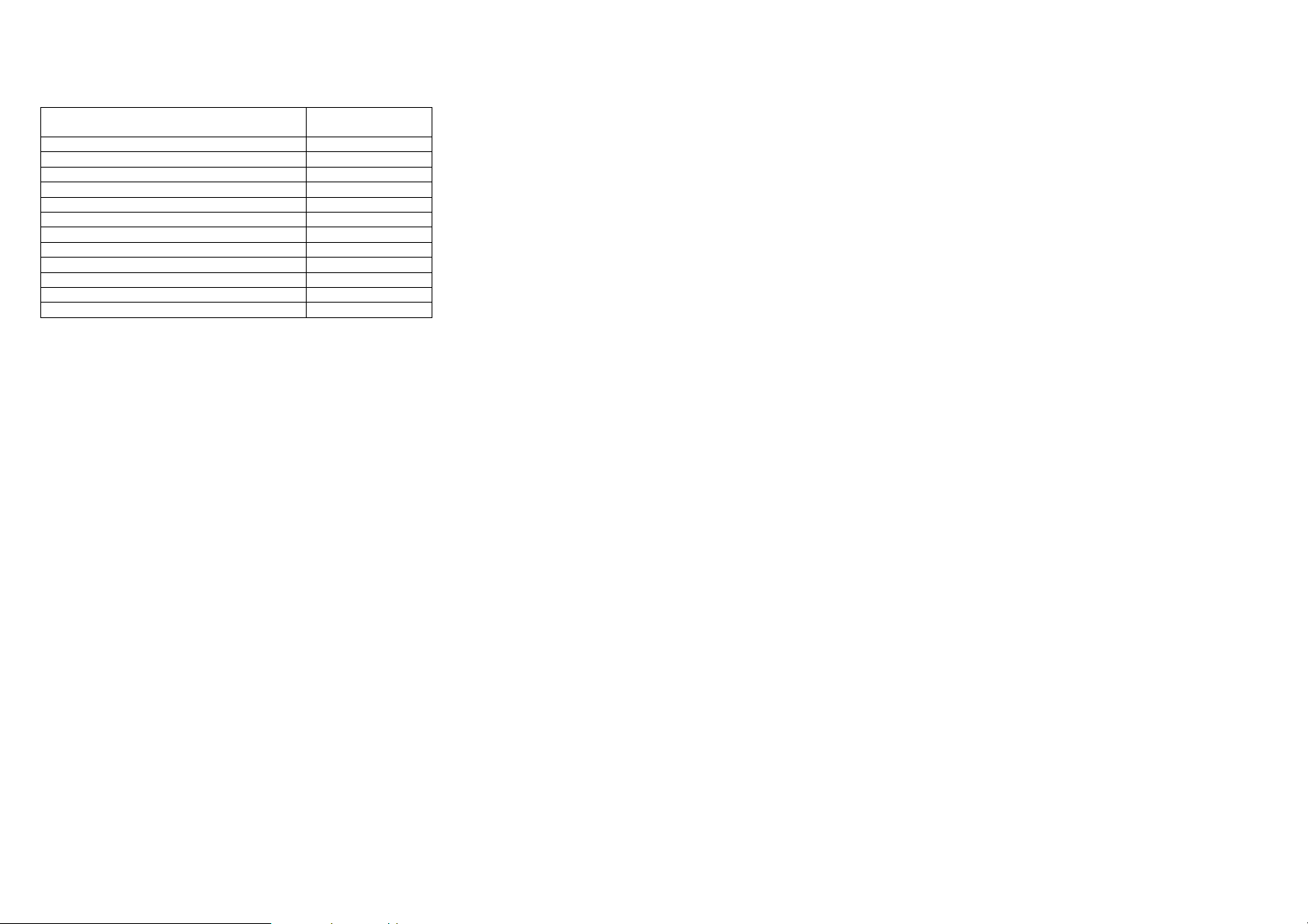
Function Display Default
Display intensity
Display reverse TURN
Feedback function ON
value
100
viti X, Y, Z
Non accendere l’apparecchio finché l’alloggiamento della lampada non sia chiuso.
Prima di riaccendere la nuova lampada resettare il contaore con la funzione “LAti”, nel
menù principale del pannello di controllo, premendo contemporaneamente i tasti “UP” e
“DOWN” e confermando con il tasto “ENTER”
REGOLAZIONE DELLA LAMPADA
La lampada viene già centrata in fabbrica. A causa di differenze tra le varie lampade,
una ulteriore regolazione fine potrebbe migliorare la qualità luminosa.
Accendere la lampada, aprire lo shutter e l’iris, portare l’intensità del dimmer al 100% e
mettere a fuoco l’impronta luminosa su una superficie piana (es. muro). Centrare la parte
più luminosa del raggio usando le tre viti di regolazione (A,B,C). Girare una vite alla volta
in modo da veder scorrere il centro luminoso del raggio lungo la diagonale dell’impronta
luminosa sul muro. Nel caso non si riesca a distinguere la parte più luminosa del raggio,
regolare la lampada, fin quando l’impronta luminosa non sia uniforme.
Per ridurre l’intensità del centro luminoso, tirare la lampada verso il riflettore, girando le
tre viti in senso orario ¼ di giro alla volta fino a quando la luce non sia uniformemente
distribuita.
viti A, B, C
Lamp OFF via DMX
Ventilation fan
ON
AUTO
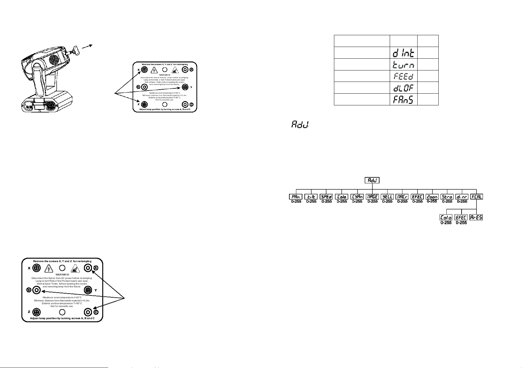
- Adjusting the default positions
By this function you can calibrate and adjust the different wheels to their standard / right
positions. Use the “UP” and “DOWN” keys to browse through the adjusting menu - the
display shows step by step these messages: "Pan”, “Tilt”, “SPEd”, “Colo”, “CYAn”,
“MAGE”, “YELL”, “MACr”, “EFEC”, “Zoom”, “Stro”, “dimr”, “FCAL" by which you can
adjust the fixture to the required / desired position (0-255) before the function calibration.
Then when the positioning is finished use the last "FCAL" function (Fixture calibration).
1. Calibration via the control board
Press “ENTER” and the “UP” and “DOWN” keys in order to display the following
messages: "Colo”, EFEC" for very smooth function calibration. Select one of them, press
“ENTER” and use the “UP” and “DOWN” keys in order to adjust their right value from 0 to
255. Then press “ENTER” to confirm or “MODE” to cancel and return to the menu. This
can be repeated for each calibration parameter if it is required. When the calibration is
finished, it is necessary to use the "ArES" function in order to write the calibration values
to the memory (EEPROM) and to make a reset in order to check the newly adjusted
positions of the colour, gobo and effect wheels. When the reset of the fixture is finished,
the display will show the "FCAL" message. Press “ENTER” to repeat the calibration or
“MODE” to return to the "AdJ" menu.
8
53
The cooling fans work on max. speed (max. cooling).
- Continuous controlling of the fan speed
- High speed of the fans
The fan automatically raises its speed in order to control inside temperature of the
lighting, if the temperature inside increases about certain level (the low fan speed
reduces the cooling of the lighting). This cycle can repeat several times until the
temperature inside is on a suitable level.
The fan keeps the adjusted low speed until the temperature exceeds max. inside temp.
of the fixture, then the PLML575E automatically switches from low to high fan-speed.
- Low / High speed of the fan operating
- Low speed / switch off the lamp operating
The fan keeps the adjusted low speed until the temperature exceeds max. inside temp.
then the PLML575E automatically switches off the lamp.
Note: In the mode “HIGH“ and “Auto“- the fan speed can’t be adjusted by DMX.
- Default settings
Press “ENTER” to reset all fixture functions to the default values. On the display will
appear “rSt” meaning that the fixture makes the reset. See the table of personality setting
and their default positions.
Function Display Default
Pan reverse OFF
Tilt reverse
Resolution ON
Lamp ON automatically
Switch ON / OFF lamp
light sensor
Display permanent ON ON
value
OFF
OFF
ON
Se l’impronta è più luminosa intorno al bordo rispetto al centro, o la luminosità è bassa,
la lampada è troppo vicina al fondo della parabola. Spingere la lampada girando le tre
viti in senso antiorario ¼ di giro alla volta fino a quando la luminosità sia maggiore ed
uniformemente distribuita.
APERTURA FASCIO
MONTAGGIO
PERICOLO: durante l’installazione considerare sempre le norme del proprio Stato.
L’installazione deve essere sempre eseguita da personale autorizzato.
L’installazione del proiettore deve essere sempre resa sicura attraverso un ancoraggio
secondario di sicurezza. Questo deve essere fatto in modo che niente possa cadere
nell’eventualità che l’ancoraggio principale venga meno.
Durante il montaggio, lo smontaggio o la manutenzione, è vietato sostare nell’area al di
sotto della zona dell’installazione, sopra ponteggi, sotto aree ad alta densità lavorativa o
in qualsiasi altra zona pericolosa.
L’operatore deve preoccuparsi che tutto quanto riguardante la sicurezza e le
caratteristiche tecniche delle macchine, sia stato approvato da persona esperta prima di
iniziare le operazioni per la prima volta o, in seguito a cambiamenti, prima di avviare le
operazioni di nuovo.
IMPORTANTE: INSTALLAZIONI IN ALTO RICHIEDONO MOLTA ESPERIENZA
relativamente ai calcoli sui carichi limite di lavoro, a tutto il materiale usato
nell’installazione ed ai controlli di sicurezza periodici su tutto quanto usato
nell’installazione (attrezzature e proiettori), mancando tali requisiti, non tentare mai di
eseguire l’installazione da soli, ma rivolgersi sempre a personale qualificato. Una errata
installazione può provocare anche danni fisici e/o economici.
52
9

Il proiettore deve essere installato al di fuori della portata delle persone.
Se la posizione del proiettore dovesse essere più bassa rispetto al soffitto o a travi alte,
bisognerà utilizzare truss professionali. Il proiettore non deve mai essere fissato in modo
che oscilli liberamente nella stanza.
ATTENZIONE: Il proiettore potrebbe provocare gravi danni in caso di caduta. In
presenza di qualsiasi dubbio riguardante la sicurezza della possibile installazione, non
installare il proiettore.
RISCHIO DI INCENDIO: al momento dell’installazione del proiettore assicurarsi che non
ci siano superfici infiammabili a distanza inferiore a 1 m
ATTENZIONE:
Usare 2 ganci appropriati per fissare l’apparecchio ad una truss. Avvitare ciascun gancio
con una vite M12 ai sostegni ad omega. Fissare il primo sostegno ad omega sulla parte
inferiore della base, utilizzando gli attacchi rapidi in dotazione. Per il fissaggio di questi,
inserirli negli appositi fori, girare in senso orario fino allo scatto. Allo stesso modo fissare
il secondo sostegno.
Assicurarsi che il fissaggio dell’apparecchio sia effettuato correttamente;
Assicurarsi che la struttura (es. truss) alla quale viene fissato l’apparecchio sia sicura.
Il testamobile può essere appoggiato sia
direttamente sul palco che ancorato ad
una truss con una qualsiasi orientazione,
senza alterarne le funzioni (vedere
disegno).
Per l’uso in alto installare sempre una
adeguata fune di sicurezza facendola
passare attraverso il foro posto al di sotto
della base.
Usare la fune di sicurezza esclusivamente
ad anello chiuso, non usarla mai
assicurando soltanto i due capi. La
massima distanza di caduta (dopo la quale
deve intervenire la fune) non deve mai
superare i 20 cm.
Una fune di sicurezza, già sottoposta a
tensione a causa di una caduta di un
proiettore, o comunque danneggiata, non
deve essere mai riutilizzata
head to the required position and press “ENTER” to confirm or “MODE” to cancel and
return to the menu.
Note: If feedbac k was switched “OFF”, the pan/tilt position is changed by external force
and feedback is switched “ON” again, the Moving Head might not to be synchronized
with the DMX signal. You have to make a reset in order to synchronize the moving head
with the DMX signal.
- Lamp off via DMX
This function allows you to switch off the lamp by DMX. Use the “UP” and “DOWN ” keys
to select "ON" if you want to switch off the lamp by DMX or "OFF" if you don’t want to
switch off the lamp by DMX and press “ENTER” to confirm or “MODE” to cancel and
return to the menu.
- Temperature
Inside temperature readouts of the fixture in Celsius. Inside temperatures below 80° C
are not critical. 80° C and more lead to the lamp being switched off. Please note that the
outside temperature should not exceed 40° C.
- Fan speed operating
By using this function you can choose 4 types of fan speed operating. Browse through
this menu by the pressing “UP” and “DOWN” keys - the display shows step by step the
following messages: "Auto”, “HIGH”, “reG”, “Lo.HI”, “Lo.OF". Press “ENTER” if you wish
to select one of them or “MODE” to cancel and return to the menu.
- Continuous controlling of the fan speed without the DMX value
This mode is similar to "reG", but the initial level of the fan speed can’t be adjusted by
DMX.
10
51

CONNESSIONE CON UNA CENTRALINA DMX / CONNESSIONE FRA APPARECCHI
- Display-adjusting
This function allows you to adjust the display settings:
- Display intensity
With this function, you can adjust the display-intensity from 20 % to 100 %. Use the “UP”
and “DOWN” keys to select the level of the display-intensity and press “ENTER” to
confirm or “MODE” to cancel and return to the menu.
- Display-reverse
With this function, you can rotate the display by 180°. Use the “UP” and “DOWN” keys to
select "normal display" or "display turned by 180°" and press “ENTER” to confirm or
“MODE” to cancel and return to the menu.
- Display-On
This function allows you to keep the display on or to turn off automatically 2 minutes after
last pressing any key on the control board. Use the “UP” and “DOWN” keys to select
"ON" if you wish to keep the display on or "OFF" if you wish to turn off automatically 2
minutes after last pressing any key on the Control Board and press “ENTER” to confirm
or “MODE” to cancel and return to the menu.
- PAN/TILT-Feedback:
This function allows to return the mowing head to the required position after changing the
position by external force (e. g. by stroke). Use the “UP” and “DOWN” keys to select
"ON" if you wish to enable this function or "OFF" if you wish not to return the moving
I cavi DMX non devono venire a contatto con altri cavi, in tal caso infatti gli apparecchi
potrebbero non funzionare correttamente o non funzionare affatto.
Usare solo cavi stereo schermati con spina e presa tipo XLR 3 poli, per la connessione
alla centralina DMX o per il collegamento tra apparecchi.
SCHEMA DI CONNESSIONE DEI CAVI DMX:
Utilizzando centraline DMX con questo schema per i connettori, è possibile connettere
l’uscita DMX della centralina all’ingresso DMX del primo proiettore della catena DMX. Se
si desidera connettere una centralina DMX con un altro tipo di uscita XLR (es. 5 poli), è
necessario disporre di un adattatore.
CREAZIONE DI UNA CATENA DMX:
Connettere l’uscita DMX del primo apparecchio della catena, all’ingresso DMX
dell’apparecchio successivo. Procedere allo stesso modo fino alla totale connessione
degli apparecchi.
DMX-output
presa XLR
1: terra
2: segnale (-)
3: segnale (+)
DMX-input
spina XLR
1: terra
2: segnale (-)
3: segnale (+)
50
11

ATTENZIONE:
Per installazioni in cui il cavo di segnale
deve percorrere lunghe distanze o dove
vi sono disturbi elettrici, per esempio in
discoteca, è consigliato l’uso di una
terminazione DMX. Il terminatore DMX è
semplicemente un connettore XLR con
collegato ad esso una resistenza da
120Ω (Ohm) tra i piedini 2 e 3. La
resistenza viene innestata nella presa
DIGITAL THRU dell’ultimo proiettore
della catena. La connessione è illustrata
a destra.
CONNESSIONE ALLA RETE DI ALIMENTAZIONE
Collegare l’apparecchio alla rete di alimentazione, attraverso il cavo incluso nella
confezione. Lo schema di connessione di tale cavo è il seguente:
La terra deve essere connessa
Il proiettore non deve essere connesso ad un dimmer-pack
Cavo Pin Simbolo
marrone fase L
blu neutro N
giallo / verde terra
FUNZIONI DEL CONTROLLO CANALI – PROTOCOLLO 16 BIT
CANALE 1: movimento orizzontale (pan)
Portare su lo slider per muovere orizzon_
talmente la testa (pan).
La testa può essere ruotata di 530° e può
essere fermata in qualsiasi posizione
intermedia desiderata.
CANALE 2: movimento orizzontale fine 16 bit
This menu allows you to turn the lamp on after switching the fixture on and switch on/off
the lamp light sensor.
- Lamp On after switching the fixture on
- Lamp On automatically
This function enables to switch on the lamp automatically after switching on the fixture.
Use the “UP” and “DOWN” keys to select “ON” if you wish to switch on the lamp
automatically after switching on the fixture or “OFF” if you wish the lamp off after
switching on the fixture and press “ENTER” to confirm or “MODE” to cancel and return to
the menu.
- Switch On/Off the lamp light sensor
Use the “UP” and “DOWN” keys to select "ON" if you wish to switch the lamp light sensor
On and press “ENTER” to confirm or “MODE” to cancel and return to the menu. The
option "ON" is for the standard operation. Use the “UP” and “DOWN” keys to select
"OFF" if you wish to switch the lamp light sensor Off and press “ENTER” to confirm or
“MODE” to cancel and return to the menu.
IMPORTANT: The option "OFF" is for emergency operation o nly if the lamp light sensor
is defective. If the lamp light sensor was switched Off, the error messages "LAEr”,
“SnEr”, “HEAt" will not appear on the display. Only the message "HEAt" will appear if the
lamp was turned Off and On within 5 minutes and at switching On of the lamp the
electronics will still try to ignite the lamp until it shines (even when the lamp is damaged
or absent), on this account some electronics parts could be damaged!
- DMX values
Readout DMX values of each channel received by the fixture. Use the “UP” and “DOWN”
keys to select desired channel and press “ENTER” to read its value coming to the fixture
or “MODE” to cancel and return to the menu.
12
49

- Reset Function
Press “ENTER” key to run reset. This option enables the PLML575E to index all effects
and return to their standard positions.
- Special functions
Use the “UP” and “DOWN” keys to browse through the special functions and select the
one by pressing “ENTER”.
- Manual control of effects
This function allows you to control manually the channel functions of the fixture. Use the
“UP” and “DOWN” keys to select desired function and press “ENTER” to adjust the
effect or “MODE” to cancel and return to the menu.
CANALE 3: movimento verticale (tilt)
Portare su lo slider per muovere vertical_
mente la testa (tilt).
La testa può essere ruotata di 280° e può
essere fermata in qualsiasi posizione
intermedia desiderata.
CANALE 4: movimento verticale fine 16 bit
CANALE 5: Velocità di pan/tilt
0÷249 Velocità (0 max ÷249 min)
250÷252
253÷255
CANALE 6: Accensione e spegnimento della lampada e velocità delle ventole di
raffreddamento
CANALE 7: ruota colori
Cambia colori lineare secondo il movimento del cursore. In questo modo è possibile
stoppare il movimento dl cursore in qualsiasi posizione si voglia anche tra due colori
creando un’immagine con doppio colore.
Fra 128 e 190 e fra 193 e 255 la ruota colori ruota continuamente questo ef fetto è
chiamato effetto “RAINBOW”
0-15 Bianco
16-31 Giallo 96-111 6000K
32-47 Viola 112-127 Filtro UV
48-63 Verde 128-190 Rainbow
64-79 Arancio 191-192 Nessuna rotazione
Massima velocità + black out durante movimento ruota colori
Massima velocità + black out durante movimento del pan/tilt, ruota colori
0÷127
128÷139
140÷229
230÷239
240÷255
Velocità delle ventole (0 max – 127 min)
Effettua il reset, accende la lampada
Nessuna funzione
Spegne la lampada dopo 3 secondi
Nessuna funzione
80-95 3200K 193-255 Rainbow
48
13

CANALE 8: Ciano
0÷255
CANALE 9: Magenta
0-255 Magenta (0 – bianco, 255 –magenta)
CANALE 10: Giallo
0-255 Giallo (0 - bianco, 255 – giallo)
CANALE 11: Velocità del CMY
CANALE 12: Macro
0-7 Off
8-15 Macro 1 136-143 Macro 17
16-23 Macro 2 144-151 Macro 18
24-31 Macro 3 152-159 Macro 19
32-39 Macro 4 160-167 Macro 20
40-47 Macro 5 168-175 Macro 21
48-55 Macro 6 176-183 Macro 22
56-63 Macro 7 184-191 Macro 23
64-71 Macro 8 192-199 Macro 24
72-79 Macro 9 200-207 Macro 25
80-87 Macro 10 208-215 Macro 26
88-95 Macro 11 216-223 Macro 27
95-102 Macro 12 224-231 Macro 28
104-111 Macro 13 232-239 Macro 29
112-119 Macro 14 240-247 Macro 30
120-127 Macro 15 248-255 Macro 31
CANALE 13: Ruota effetti
Ciano (0 – bianco, 255 – ciano)
0 Velocità massima
255 Velocità minima
128-135 Macro 16
0 -70 Full beam
1÷179
180÷191
Beam Shaper
Filtro frost
- Movement resolution
By this function you can adjust the desired movement resolution 8 or 16 bit. Use the “UP”
and “DOWN” keys to select “ON” if you wish the 16bit high resolution or "OFF" if you
wish only 8 bit resolution and press “ENTER” to confirm or “MODE” to cancel and return
to the main menu.
Note:
If you adjust the 16 bit resolution the fixture will occupy 16 DMX channels, if you adjust
the 8 bit resolution, the fixture will be operated by only 14 DMX channels.
- Lamp On time
This option enables you to read the total number of hours that the lamp has been
powered on. Press “ENTER” or “MODE” to return to the main menu. In order to reset the
counter to 0, you have to hold the “UP” and “DOWN” button an d press the “ENTER”
button.
- Power On time
By this option you can read the total number of hours that the PLML575E has been
powered on. Press “ENTER” or “MODE” to return to the main menu.
- Switch on / off the lamp
Use the “UP” and “DOWN” keys to select "ON" if you wish the switch on the lamp or
"OFF" if you wish switch off the lamp and press “ENTER” to confirm or “MODE” to cancel
and return to the main menu.
- Demo sequences
This function allows you to run a special demo-test sequences without an external
controller, which will show you some possibilities of using PLML575E. Press “UP” and
“DOWN” keys to select the "MOD1" or "MOD2" sequences. The "MOD1" is suitable for
projections on the wall, ceilling or ground without any head movement, the "MOD2" uses
all PLML575E functions and therefore is good for a complete introduction of the fixture.
14
47

FAN
The PLML575E is cooled by three axial fans - one each in the projector head and one in
the base. The speed of the fan (and of course the noise) can be continuously reduced if
very quiet performance is required. By the Control Board using the "FAnS" function you
can choose 5 types of low fan speed operating. Please refer to the instructions under
SPEC - Special functions.
CONTROL BOARD
The Control Board situated on the top side of the PLML575E offers several features. You
can simply set the lighting address, read the number of lamp or unit hours, switch on and
off the lamp, run demonstration sequences, make a reset and also use special functions
for manual control and service purposes. The main menu is accessed by pressing the
“MODE” key - press this one so many times until the display shows message "A001"
(with actually stored address). Browse through the menu by the pressing “UP” and
“DOWN” keys - the display shows step by step these messages: “A001”, “rPAn”, “rTilt”,
“16br”, “Lati”, “Poti”, “LAMP”, “dEMo”, “rESE”, “SPEC”. Press “ENTER” if you wish to
select one of them. The functions provided are described in the following sections and
the function hierarchy is shown below.
MAIN FUNCTIONS
- DMX 512 Address settings
The letter "A" flashes. Use the “UP” and “DOWN” keys to select required address (001 -
512) and press “ENTER” to confirm or “MODE” to cancel and return to the main menu.
- Pan reverse
This function allows you to invert the Pan-movement. Use the “UP” and “DOWN” keys to
select "ON" if you wish this feature or "OFF" if you don’t wish this feature and press
“ENTER” to confirm or “MODE” to cancel and return to the main menu.
- Tilt reverse
This function allows you to invert the Tilt-movement. Use the “UP” and “DOWN” keys to
select "ON" if you wish this feature or "OFF" if you don’t wish this feature and press
“ENTER” to confirm or “MODE” to cancel and return to the main menu.
CANALE 14: Zoom
0 Zoom 28°
255 Zoom 7°
CANALE 15: Shutter – strobe
0÷31
32÷63
64÷95
96÷127
128÷159
160÷191
192÷223
224÷255
Shutter chiuso
Nessuna funzione (shutter aperto)
Effetto strobo da lento a veloce
Nessuna funzione (shutter aperto)
Effetto pulsazione
Nessuna funzione (shutter aperto)
Strobo casuale
Nessuna funzione (shutter aperto)
CANALE 16: Dimmer
Dimmer da 0% a 100%
0÷255
FUNZIONI DEI CANALI DI CONTROLLO – PROTOCOLLO 8 BIT
1 2 3 4 5 6 7 8 9 10 11 12 13 14
canali
DMX
funzione
Pan Tilt Velocità
Pan/tilt
colori Ciano Magenta Giallo Velocità
Ventole
On/off
lampada
Macro Effetti - Strobo Dimmer
CMY
INDIRIZZAMENTO
Il pannello di controllo sul lato anteriore del PML575E vi permette di assegnare
all’apparecchio l’indirizzo DMX dal quale l’apparecchio risponderà al controllore.
Se per esempio settate come indirizzo il canale 5 il PLML575E userà i canali da 5 a 20
per il controllo.
Assicurarsi che non ci siano canali sovrapposti in modo da poter controllare ogni
PLML575E separatamente e in modo indipendente.
Se due o più PLML575E sono indirizzati con gli stessi canali essi lavoreranno allo stesso
modo.
Per settare l’indirizzo seguire la seguente procedura:
1. accendere il PLML575E e attendere che l’apparecchio esegua il reset (“rSt”
lampeggia sul display)
2. premere il tasto “MODE” per accedere al menu principale. Scorrere il menu
principale premendo i tasti “UP” e “DOWN” fino a quando il display mostra
“A001”. Confermare premendo “ENTER” e la lettera “A” lampeggerà
3. usare i tasti “UP” e “DOWN” per selezionare l’indirizzo desiderato.
4. confermare premendo “ENTER” .
46
15

CONTROLLI
Dopo aver indirizzato tutti i PLML575E si possono iniziare le operazioni attraverso la
centralina delle luci.
Note:
Dopo averlo acceso il PLML575E controllerà automaticamente se sta ricevendo i dati dal
DMX o no. Se non ci sono dati in input sul display inizierà a lampeggiare “A001” cioè
l’indirizzo attualmente settato.
Questa situazione avviene se:
Il connettore DMX in ingresso al proiettore o il connettore in uscita dalla centralina
non sono connessi, oppure la centralina è spenta o difettosa.
LAMPADA
Il PLML575E deve operare con una lampada HSR 575 oppure MSR 575
Il PLML575E permette di accendere spegnere il la lampada attraverso il pannello di
controllo sul lato anteriore o attraverso la vostra centralina.
ACCENSIONE E SPEGNIMENTO DELLA LAMPADA ATTRAVERSO IL PANNELLO
DI CONTROLLO
1. accendere il PLML575E e attendere fino a quando la macchina abbia finito il
reset.
2. premere il tasto “MODE” per accedere al menu principale. Scorrere il menu
principale usando i tasti “UP” e “DOWN” fino a quando sul display non
appare “LAMP”. Confermare premendo il tasto “ENTER”
3. utilizzare i tasti “UP” e “DOWN” per selezione “ON” per accendere la lampada
e “OFF” per spegnere la lampada.
Note:
È importante notare che la lampada a scarica deve essersi raffreddata prima di poter
essere riaccesa. Per questa ragione bisogna aspettare almeno 5 minuti (se si è regolato
al massimo la velocità delle ventole) dallo spegnimento della lampada prima che sia
possibile riaccenderla. Se si tenta di accendere la lampada prima che i cinque minuti
siano trascorsi il PLML575E registra questa informazione e quando sono passati 5
minuti accende la lampada, nel frattempo il messaggio “HEAt” apparirà sul display del
pannello anteriore del PLML575E. Se l’accensione della lampada fallisce per sette volte
di seguito sul display appare il messaggio “LA.Er” che significa che la lampada può
essere danneggiata o può mancare, oppure l’accenditore può essersi rovinato.
RUOTA COLORI
Il PLML575E è dotato di una ruota colori con 7 filtri dicroici + bianco. Quattro di questi
filtri con colori, un filtro di correzione 3200K, un filtro 6000K ed un filtro UV. La ruota può
essere posizionata tra due colori adiacenti in qualsiasi posizione. E’ inoltre possibile
ruotare la ruota in maniera continua a differenti velocità (effetto rainbow).
SWITCHING ON AND OFF THE LAMP VIA THE CONTROL BOARD
1. Switch on the PLML575E and wait until the fixture reset has finished.
2. Press the “MODE” key in order to access the main menu. Bro wse through the
menu by pressing the “UP” and “DOWN” keys until the display shows "LAMP".
Confirm by pressing “ENTER” key.
3. Use the “UP” and “DOWN” keys to select "ON" for switching on the lamp and
"OFF" for switch off the lamp and press “ENTER” to confirm or “MODE” to
cancel.
Note :
It is also important to note that the discharge lamp is a cold restrike type, which means
that it has to be cold before re-striking. For this reason, you have to wait 5 minutes (max.
speed of fan must be adjusted) after having switched off the lamp before you can switch
it back on again. If you try to switch on the lamp within 5 minutes after having switched it
off, the PLML575E will store this information and automatically ignite the lamp when the
5 minutes period has expired. The message "HEAt" will appear on the control board
display at the back side of the PLML575E. If the ignition of the lamp is seven times
unsuccessful, on the display will appear "LA.Er", meaning that the lamp could be
damaged or even missed, or there could be a failure on the ignitor or ballast.
COLOUR-WHEEL
The PLML575E features a colour-wheel with 8 color positions - 4 of these with dichroic
colors, correction-filters 3200 K and 6000 K, UV-filter and the last one open. The wheel
can be positioned between two adjacent colors in any position. It is also possible to
rotate the color-wheel continuously at different speeds - the socalled "Rainbow effect“ is
created.
CMY- Colour-mixture
The CMY color mixing system is based on graduated cyan, magenta, and yellow color
filters. A continuous range of colors may be achieved by varying the amount of each filter
from 0 to 100%.
BEAM-EFFECTS
The beam-shaper allows you to widen and flatten beam. Beam shaper rotates within
180°. Frost-filter on the same wheel as beam shaper softens the beam.
ZOOM
Via the motorized zoom, the radiation angle can be adjusted between 7° and 28°.
DIMMER
Smooth 0 - 100 % dimming is provided by the dimmer-unit.
SHUTTER / STROBE
This unit provides strobe-effects between 1 and 10 flashes per second.
16
45

FUNCTION OF THE CONTROL CHANNELS - 8 BIT PROTOCOL:
1 2 3 4 5 6 7 8 9 10 11 12 13 14
DMX
channels
function Pan Tilt Pan/tilt
speed
Fan
On/off
lamp
Colours Cyan Magenta Yellow CMY
speed
Macro Effects - Strobe Dimmer
ADDRESSING
The Control Board on the top side of the PLML575E allows you to assign the DMX
fixture address, which is defined as the first channel from which the PLML575E will
respond to the controller. If you set, for example, the address to channel 5, the
PLML575E will use the channel 5 to 20 for control.
Please, be sure that you don’t have any overlapping channels in order to control each
PLML575E correctly and independently from any other fixture on the DMX data link.
If two, three or more PLML575E are addressed similarly, they will work similarly.
For address setting follow this procedure:
1. Switch on the PLML575E and wait until the fixture reset has finished ("rSt" is
flashing at the display).
2. Press the “MODE” key in order to access the main menu. Bro wse through the
menu by pressing the “UP” and “DOWN” keys until the display shows "A001".
Confirm by pressing “ENTER” key and the letter "A" will flash.
3. Use the “UP” and “DOWN” keys to select the desired address.
4. Confirm by pressing “ENTER” or “MODE” to cancel.
CONTROLLING
After having addressed all PLML575E , you may now start operating these via your
lighting controller.
Note:
After switching on, the PLML575E will automatically detect whether DMX 512 data is
received or not. If there is no data received at the DMX-input, the display will start to
flash "A001" with actually set address.
This situation can occurr if:
the 3 PIN XLR plug (cable with DMX signal from controller) is not connected with
the input of the PLML575E, or the controller is switched off or defective.
LAMP
The PLML575E is to be operated with a HSR 575 or MSR 575 lamp.
A relay inside of the PLML575E allows you to switch on and off the lamp via the Control
Board on the top side or via your controller.
CMY – miscelazione dei colori
Il sistema di miscelazione dei colori CMY è basato sulla gradazione dei filtri colore giallo,
ciano e magenta. Attraverso la variazione della percentuale di ognuno dei tre colori si
può ottenere una gamma di colori infinita.
BEAM EFFECT
Il beam shaper permette di appiattire il fascio luminoso. Il fascio può ruotare di 180° .
FOCUS
Lente motorizzata.
DIMMER
L’unità dimmer permette un dimmeraggio fra compreso fra lo 0-100%
SHUTTER / STROBE
Questa unità permette un effetto strobo con una frequenza compresa fra 1 e 10 flash al
secondo.
VENTOLE
Il PLML575E è raffreddato da tre ventole assiali una in ogni lato del testa del proiettore
e un’altra nella base del proiettore. La velocità delle ventole (e di conseguenza la
rumorosità) può essere ridotta con continuità se è richiesto un funzionamento molto
silenzioso.
Attraverso il pannello di controllo usando la funzione “FAnS” si possono scegliere 5 modi
per far operare le ventole a bassa velocità. Riferirsi alle istruzioni sotto il menù SPEC funzioni speciali.
PANNELLO DI CONTROLLO
Il pannello di controllo situato sul lato anteriore del PLML575E offre molte opzioni. Si può
settare facilmente l’indirizzo DMX, leggere le ore di funzionamento della lampada e
dell’apparecchio, accendere e spegnere la lampada,attivare delle sequenza demo,
effettuare un reset ed inoltre utilizzare speciali funzioni per il controllo manuale o il
service. Al menu principale si accede premendo il tasto “MODE” - premere tante volte
fino a quando sul display non compare la scritta “A001” (o l’indirizzo attualmente
memorizzato). Scorrere le voci di menù premendo i tasti “UP” e “DOWN”, il display
visualizzerà una dopo l’altra le seguenti voci: “A001”, “rPAn”, “rTilt”, “16br”, “LAti”, “Poti”,
“LAMP”, “dEMo”, “rESE”, “SPEC”. Premere “ENTER” per selezionare una voce.
44
17

Le funzioni di ciascuna di tali voci sono descritte nelle sezioni successive; la sequenza
sul menù è indicata di seguito:
FUNZIONI PRINCIPALI
- DMX settaggio dell’indirizzo .
Quando la lettera “A” lampeggia. Usare i tasti “UP” e “DOWN” per selezionare l’indirizzo
richiesto (001 - 512) poi premere il tasto “ENTER” per confermare o il tasto “MODE” per
cancellare e ritornare al menu principale.
– Pan Reverse
Questa funzione permette di invertire il movimento del Pan. Usare i tasti “UP” e “DOWN”
e selezionare “ON” per attivarla oppure “OFF” per disattivarla, poi premere “ENTER” per
confermare oppure il tasto “MODE” per cancellare e ritornare al menu principale.
– Tilt Reverse
Questa funzione permette di invertire il movimento del Tilt. Usare i tasti “UP” e “DOWN”
e selezionare “ON” per attivarla oppure “OFF” per disattivarla, poi premere “ENTER” per
confermare oppure il tasto “MODE” per cancellare e ritornare al menu principale.
– Risoluzione del movimento
Attraverso questa funzione si può regolare la risoluzione del movimento fra 8 e 16 bit.
Usare i tasti “UP” e “DOWN” per selezionare “ON” per regolare la risoluzione a 16 bit
oppure “OFF” se si vuole una soluzione a 8 bit poi premere “ENTER” per confermare
oppure il tasto “MODE” per cancellare e ritornare al menu principale
Nota:
Se si seleziona la risoluzione a 16 bit l’apparecchio occuperà 16 canali DMX nel caso si
seleziona la risoluzione a 8 bit l’apparecchio occuperà solo 14 canali DMX.
– Tempo di accensione lampada
Questa funzione permette di leggere il numero totale di ore che la lampada è stata
accesa. Premere “ENTER” oppure “MODE” per ritornare al menu principale. Per
riportare a 0 il contatore occorre tenere premuti i tasti “UP” e “DOWN” e premere il tasto
“ENTER”
CHANNEL 12 - Colour-macros - CMY and colour-wheel
CHANNEL 13 - Effect-wheel
CHANNEL 14 – Zoom
CHANNEL 15 - Shutter, Strobe
CHANNEL 16 - Dimmer intensity
0-7 Off 128-135 Macro 16
8-15 Macro 1 136-143 Macro 17
16-23 Macro 2 144-151 Macro 18
24-31 Macro 3 152-159 Macro 19
32-39 Macro 4 160-167 Macro 20
40-47 Macro 5 168-175 Macro 21
48-55 Macro 6 176-183 Macro 22
56-63 Macro 7 184-191 Macro 23
64-71 Macro 8 192-199 Macro 24
72-79 Macro 9 200-207 Macro 25
80-87 Macro 10 208-215 Macro 26
88-95 Macro 11 216-223 Macro 27
95-102 Macro 12 224-231 Macro 28
104-111 Macro 13 232-239 Macro 29
112-119 Macro 14 240-247 Macro 30
120-127 Macro 15 248-255 Macro 31
0÷31
32÷63
64÷95
96÷127
128÷159
160÷191
192÷223
224÷255
0 -70 Full beam
1÷179
180÷191
Shutter closet
No function (shutter open)
Strobe effect from slow to fast
No function (shutter open)
Pulse effect in sequences
No function (shutter open)
Random strobe effect from slow to fast
No function (shutter open)
0÷255
Beam Shaper
Frost Filter
0 Zoom 28°
255 Zoom 7°
Dimmer from 0% to 100%
18
43

CHANNEL 5 - Speed of PAN / TILT movement
0÷249 Speed (0 max ÷249 min)
250÷252
253÷255
CHANNEL 6 - Switch on / off the lamp, reset, speed control of cooling fan
CHANNEL 7 - Colour-wheel
Linear colour change following the movement of the slider. In this way you can stop the
colour-wheel in any position - also between two colours creating double-coloured beams.
Between 128 and 190 and between 193 and 255, the colour-wheel rotates continuously
the so-called "Rainbow" effect.
0-15 White
16-31 Yellow 96-111 6000K
32-47 Violet 112-127 UV Filter
48-63 Green 128-190 Rainbow
64-79 Orange 191-192 No rotation
CHANNEL 8 – Cyan
CHANNEL 9 – Magenta
CHANNEL 10 – Yellow
CHANNEL 11 - Speed of CMY and dimmer
Max speed + black-out colour changes
Max speed + black-out while pan/tilt moving or colour changes
0÷127
128÷139
140÷229
230÷239
240÷255
Speed of fan (0 max – 127 min)
Switch on the lamp, reset, open position
No function
Switch off the lamp after 3 seconds
No function
80-95 3200K 193-255 Rainbow
Cyan (0 – white, 255 – cyan)
0÷255
0-255 Magenta (0 – white, 255 –magenta)
0-255 Yellow (0 - white, 255 – yellow)
0 Max speed
255 Min speed
– Tempo di accensione apparecchio
Questa funzione permette di leggere il numero totale di ore che il PLML575E è stato
acceso. Premere “ENTER” oppure “MODE” per ritornare al menu principale.
– Accensione / Spegnimento lampada
Usare i tasti “UP” e “DOWN” e selezionare “ON” per accendere la lampada oppure
“OFF” se per spegnere la lampada poi premere “ENTER” per confermare oppure
“MODE” per cancellare e ritornare al menu principale.
– Sequenze demo
Questa funzione permette di attivare dei test dimostrativi senza una centralina esterna.
Premere i tasti “UP” e “DOWN” per selezionare la sequenza “MOD1” oppure “MOD2”
“MOD1” è una sequenza adatta per proiezioni sul muro, soffitto o pavimento senza
movimenti della testa, la sequenza “MOD2” usa tutte le funzioni del PLML575E e perciò
è utile per una dimostrazione completa della macchina.
- Reset
Premere il tasto “ENTER” per attivare il reset. Questa opzione permette al PLML575E
di ritornare alla sua posizione standard
– Funzioni speciali
Usare i tasti “UP” e “DOWN” per selezionare una delle funzioni speciali contenute
all’interno e selezionare premendo il tasto “ENTER”
42
19

Questa funzione permette il controllo manuale delle funzioni dei canali dell’apparecchio.
Usare i tasti “UP” e “DOWN” per selezionare la funzione desiderata poi premere
“ENTER” per regolare l’effetto selezionato oppure “MODE” per uscire e ritornare al
menu.
Questo menu permette di accendere la lampada dopo aver acceso l’apparecchio e
controllarne il sensore.
Questa funzione permette di accendere la lampada automaticamente dopo aver acceso
l’apparecchio. Usare i tasti “UP” e “DOWN” e selezionare “On” per accendere
automaticamente la lampada dopo aver acceso l’apparecchio, selezionare “Off” per non
accendere automaticamente la lampada poi premere “ENTER” per confermare oppure
“MODE” per cancellare e tornare al menu.
Usare i tasti “UP” e “DOWN” per attivare il sensore luminoso e premere “ENTER” per
confermare oppure “MODE” per cancellare e tornare al menu. L’opzione “ON” è per il
funzionamento standard.
Usare i tasti “Up” e “DOWN” e selezionare “OFF” per disattivare il sensore luminoso poi
premere “ENTER” per confermare oppure “MODE” per cancellare al menu.
– Controllo manuale degli effetti
– Accensione automatica della lampada
– Accensione della lampada dopo l’accensione dell’apparecchio
– Accensione / Spegnimento sensore di luminosità
CONNECTION WITH THE MAINS
Connect the device to the mains with the enclosed power supply cable.
The occupation of the connection-cables is as follows:
The earth has to be connected.
Lighting effects must not be connected to dimming-packs.
Cable Pin International
brown live L
blue neutral N
yeLow / green earth
FUNCTION OF THE CONTROL CHANNELS - 16 BIT PROTOCOL
CHANNEL 1 - Horizontal movement (Pan)
Push slider up in order to move head
horizontally (PAN). Gradual head
adjustment from one end of the slider to
the other (0-255, 128-center). The head
can be turned by 530°
and stopped at any position you wish.
CHANNEL 2 - Pan fine 16 bit
CHANNEL 3 - Vertical movement (Tilt)
Push slider up in order to move head
vertically (TILT). Gradual head
adjustment from one end of the slider to
the other (0-255, 128-center). The head
can be turned by 280° and stopped at
any position you wish.
CHANNEL 4 - Tilt fine 16 bit
20
41

The DMX wires must not come into contact with each other, otherwise the fixtures will
not work at all, or will not work properly.
Only use a stereo shielded cable and 3-pin XLR-plugs and connectors in order to
connect the controller with the fixture or one fixture with another.
OCCUPATION OF THE XLR-CONNECTION:
DMX-output
XLR mounting socket
1: ground
2: signal (-)
3: signal (+)
DMX-input
XLR mounting socket
1: ground
2: signal (-)
3: signal (+)
IMPORTANTE: l’opzione “OFF” serve solo per un utilizzo di emergenza nel caso in cui il
sensore sia difettoso. Se il sensore luminoso è spento non appariranno sul display i
messaggi di errore “LAEr”, SnEr,”. Solo il messaggio HEAt apparirà se la lampada viene
spenta e poi riaccesa prima di 5 minuti o quando essa è danneggiata o assente e
l’accenditore elettronico tenta di accendere la lampada senza riuscirvi.
– Valore DMX
Permette la lettura del valore del DMX ricevuto per ogni canale. Usare i tasti “UP” e
“DOWN” per selezionare il canale desiderato, poi premere “ENTER” per confermare
oppure “MODE” per cancellare e tornare al menu.
If you are using the recommended controllers, you can connect the DMX-output of the
controller directly with the DMX-input of the first fixture in the DMX-chain. If you wish to
connect DMX controllers with other XLR-outputs, you need to use adapter-cables.
BUILDING A SERIAL DMX-CHAIN:
Connect the DMX-output of the first fixture in the DMX-chain with the DMX-input of the
next fixture. Always connect one output with the input of the next fixture until all fixtures
are connected.
CAUTION:
For all installation, having long signal
cables or in the presence of electrical
noise, for example a discotheque, it is
recommended practice to use a DMX
terminator: this assist in preventing
corruption of the digital control signal by
external noise. The DMX terminator is
simply an XLR connector with a 120Ω
(Ohm) resistor connected across pins 2
and 3, wich is then plugged into the
DIGITAL THRU socket on the last
projector in the chain. The connection
are illustrated on the right.
– Regolazione display
Questa funzione permette di regolare il display
– Intensità display
Con questa funzione si può selezionare l’intensità del display dal 20% al 100%.
Utilizzare i tasti “Up” e “DOWN” per selezionare il livello di intensità del display poi premi
“ENTER” per confermare oppure “MODE” per ritornare al menu.
– Inversione display
Attraverso questa funzione si può ruotare il display di 180°. Usare i tasti “UP” e “DOWN”
per selezionare “display normale” oppure “display ruotato di 180°” poi premi “ENTER”
per confermare oppure “MODE” per cancellare e tornare al menu.
40
21

– Accensione display
Questa funzione permette di decidere se tenere il display sempre acceso oppure se farlo
spegnere 2 minuti dopo che è stato premuto un tasto per l’ultima volta sul pannello di
controllo. Usare i tasti “UP” e “DOWN” per selezionare “ON” se lo si vuole tenere
acceso oppure “OFF” per spegnerlo automaticamente, poi premere il tasto “ENTER” per
confermare oppure “MODE” per cancellare e tornare al menu.
– Controllo pan/tilt
Questa funzione fa si che la testa mobile recuperi la vecchia posizione dopo che è stata
cambiata da una forza esterna (esempio viene urtato). Usare i tasti “Up” e “DOWN” e
selezionare “ON” per abilitare questa funzione oppure “OFF” per disabilitarla. Premere
il tasto “ENTER” per confermare oppure “MODE” per cancellare e tornare al menu.
Nota: nel caso una forza esterna sposti il pan/tilt mentre questa funzione è settata su
“OFF” se si mette successivamente a “ON” potrebbe accadere che il testa mobile non
sia sincronizzato con il segnale del DMX per questo motivo è necessario fare un reset
che permetta la sincronizzazione.
– Controllo lampada via DMX
Questa funzione permette di spegnere la lampada attraverso il DMX. Usare i tasti “Up” e
“DOWN” e selezionare “On” per avere la possibilità di spegnere la lampada tramite il
DMX oppure “OFF” per togliere questa possibilità, poi premere il tasto “ENTER” per
confermare oppure “MODE” per cancellare e tornare al menu.
– Temperatura
Questa funzione permette la lettura della temperatura interna dell’apparecchio in gradi
celsius. Temperature interne sotto gli 80° C non sono pericolose. Temperature superiori
agli 80° portano allo spegnimento della lampada. La temperatura esterna non deve
eccedere i 40° C.
– Regolazione velocità ventole
Utilizzando questa funzione è possibile selezionare 5 differenti velocità delle ventole.
Scorrendo questo menu tramite i tasti “Up” e “DOWN” il display mostrerà passo dopo
passo i seguenti messaggi: ”Auto”, “HIGH”, “reG”, “Lo.HI”, “Lo.Of”. Premere il tasto
“ENTER” per selezionare una opzione oppure premere “MODE” per cancellare e tornare
al menu.
If the projector shall be lowered from the ceiling or high joists, professional trussing
systems have to be used. The projector must never be fixed swinging freely in the room.
CAUTION: projectors may cause severe injuries when crashing down! If you have
doubts concerning the safety of a possible installation, do NOT install the projector.
DANGER OF FIRE: when installing the device, make sure there is no highly-inflammable
material (decoration articles, etc.) within a distance of min. 1 m.
CAUTION!
Use 2 appropriate clamps to rig the fixture on the truss. Screw one clamp each via a M12
screw and nut onto the omega holders. Insert the quick-lock fasteners of the first omega
holder into the respective holes on the bottom of the device. Tighten the quick-lock
fasteners fully clockwise. Install the second omega holder.
Make sure that the device is fixed properly.
Ensure that the structure (truss) to which you are attaching the fixtures is secure.
The Moving-Head can be placed directly
on the stage-floor or rigged in any
orientation on a truss without altering its
operation characteristics (see the
drawing).
For overhead use, always install a
safety-rope. Pull the safety rope
through the ole on the bottom of the
base.
Use a safety rope exclusively as a
closed ring. Never use by only securing
at each end. The maximum drop
distance must never exceeded 20 cm.
A safety rope which already hold the
strain of a crash or which is defective
must not be used again.
DMX-512 CONNECTION / CONNECTION BETWEEN FIXTURES
22
39

BEAMPATH
RIGGING
DANGER TO LIFE: Please consider the respective national norms during the installation.
The installation must only be carried out by an authorized dealer.
The installation must always be secured with a secondary safety attachment, e.g. an
appropriate catch net. This secondary safety attachment must be constructed in a way
that no part of the installation can fall down if the main attachment fails.
When rigging, derigging or servicing the fixture staying in the area below the installation
place, on bridges, under high working places and other endangered areas is forbidden.
The operator has to make sure that safety-relating and machine-technical installations
are approved by an expert before taking into operation for the first time and after
changes before taking into operation another time.
The operator has to make sure that safety-relating and machine-technical installations
are approved by anexpert after every four year in the course of an acceptance test.
The operator has to make sure that safety-relating and machine-technical installations
are approved by askilled person once a year.
IMPORTANT! OVERHEAD RIGGING REQUIRES EXTENSIVE EXPERIENCE, including
(but not limited to) calculating working load limits, installation material being used, and
periodic safety inspection of all installation material and the projector. If you lack these
qualifications, do not attempt the installation yourself, but instead use a professional
structural rigger. Improper installation can result in bodily injury and/or damage to
property.
The projector has to be installed out of the reach of people.
- Controllo continuo della velocità delle ventole senza DMX
Questo modo è simile a “rEG”, ma il livello iniziale della velocità delle ventole non può
essere controllato attraverso il DMX.
– Massima velocità delle ventole
Le ventole di raffreddamento lavorano alla massima velocità (massimo raffreddamento)
– Controllo continuo della velocità delle ventole
Le ventole aumentano automaticamente la loro velocità per controllare l’aumento della
temperatura interna.
– Minima / massima velocità delle ventole durante il funzionamento
Le ventole mantengono la velocità selezionata fino a quando la temperatura interna non
eccede il massimo, a questo punto il PLM575SE automaticamente porterà le ventole alla
massima velocità.
– Bassa velocità / spegnimento lampada duraante il funzionamento
Le ventole raggiungono la velocità selezionata fino a quando la temperatura non eccede
il massimo, allora il PLM575E automaticamente spegnerà la lampada
Nota: nella modalità “HIGH” e “Auto” la velocità delle ventole non può essere regolata
dal DMX.
– Impostazioni di default
Premere “ENTER” per resettare tutte le funzioni dell’apparecchio al valore di default, Sul
display apparirà “rSt” che indica che l’apparecchio sta facendo il reset. Vedere sotto la
tabella delle funzioni ed il loro valore di default.
38
23

Funzione Display Valore di
Inversione del Pan OFF
Inversione del Tilt
Risoluzione ON
Accensione automatica
della lampada
Accensione / spegnimento
del sensore di luminosità
Display sempre acceso ON
Intensità display
Inversione display TURN
Controllo Pan / Tilt ON
Spegnimento della lampada
via DMX
Ventole di raffreddamento
default
OFF
OFF
ON
100
ON
AUTO
Do not operate this device with opened cover.
Before striking the lamp, reset the "LAti" counter in the main menu of the Control Board,
by pressing the "UP" and "DOWN" buttons in one time and then confirming with the
Enter-button.
LAMP ADJUSTMENT
The lampholder is aligned at the factory. Due to differences between lamps, fine
adjustment may improvelight performance.
Strike the lamp and open the shutter, set the dimmer intensity onto 100% and direct the
light on a flat surface (wall). Center the hot-spot (the brightest part of the beam) using the
3 adjustment screws “A, B, C”. Turn one screw at a time to drag the hot-spot diagonally
across the projected image. If you cannot detect a hot-spot, adjust the lamp until the light
is even.
To reduce a hot-spot, pull the lamp in by turning all three screws “A, B, C” clockwise ¼turn at a time until the light is evenly distributed.
Tramite questa funzione è possibile calibrare e regolare la posizione delle ruote al loro
giusto valore. Usando i tasti “Up” e “DOWN” per scorrere il menu – il display mostrerà
passo dopo passo i seguenti messaggi: “Pan”, “Tilt”, “SPEd”, “Colo”, “CYAn”, “MAGE”,
“YELL”, “MACr”, “EFEC”, “Zoom”, “Stro”, “dimr”, “FCAL” attrverso i quali è possibile
regolare l’apparecchio alla posizione desiderata, quando poi la calibrazione è finita è
necessario usare la funzione “FCAL”.
1. Calibrazione tramite pannello di controllo
Premere “ENTER” e “UP” e ”DOWN” per scorrere i seguenti messaggi: “Colo”, “EFec”
per calibrazioni molto precise. Usare i tasti “Up” e “DOWN” per selezionare una delle
– Regolazione posizione di default
24
screws A, B, C
If the light is brighter around the edge than it is in the center, or if light output is low, the
lamp is too far back in the reflector. "Push” the lamp out by turning the screws “A, B, C”
counterclockwise ¼-turn at a time the light is bright and evenly distributed.
37

If this device will be operated in any way different to the one described in this manual,
the product may suffer damages and the guarantee becomes void. Furthermore, any
other operation may lead to dangers like short-circuit, burns, electric shock, lamp
explosion, crash etc.
INSTALLATION
FITTING / EXCHANGING THE LAMP
DANGER: Install the lamp with the device switched off only. Unplug from mains before.
For the installation you need one HSR575 / MSR575 lamp or equivalent, respecting the
manufacturer’s specifications.
CAUTION: the lamp has to be replaced when it is damaged or deformed due to the heat.
During the operation, the lamp reaches temperatures up to 600°C.
Before replacing the lamp, unplug mains lead and let the lamp cool dow n (approx.
10 minutes)
During the installation do not touch the glass bulb bare-handed. Please follow the lamp
manufacturer’s notes.
Do not install lamps with a higher wattage. Lamps with a higher wattage generate
temperatures that the device was not designed for. Damages caused by non observance
are not subject to warranty.
REPLACING THE LAMP
1. Unscrew the fixation screws (X, Y, Z) of the lamp cover and remove it
2. If replacing the lamp, remove the hold lamp from the lamp holder
3. Insert the new lamp into the lamp holder
4. Replace the lamp cover and tighten the fixation screws (X, Y, Z)
5. Adjust the lamp as described under lamp adjustment
screws
X, Y, Z
voci poi premere “ENTER” e usare i tasti “UP” e “DOWN” per regolare il giusto valore
fra 0 e 255. Premere “ENTER” per confermare oppure “M ODE” per tornare al menu.
Questa operazione deve essere ripetuta per ogni parametro da calibrare. Quando la
calibrazione è finita, per scrivere l’impostazione sulla memoria (EEPROM), è necessario
usare la funzione “ArES” e successivamente fare un reset per verificare le nuove
impostazioni. Quando il reset dell’apparecchio sarà finito il display mostrerà il messaggio
“FCAL”. Premere “ENTER” per ripetere la calibrazione oppure “MODE” per ritornare al
menu.
Calibrazione attraverso controllore esterno
2.
Premere “ENTER” e i tasti “Up” e “DOWN” per far apparire sul display i seguenti
messaggi: “Colo”, “EFEC” – parametri di calibrazione. Selezionarne uno e premere
“ENTER”.
Ora è possibile calibrare i colori, e la ruota effetti attraverso la centralina. Il protocollo di
alibrazione tramite DMX è descritto nelle tabelle sotto riportate.
c
Canale
DMX
Funzione
Canale
DMX
1 2 3 4 5 6 7 8
colore Effetti - - - - Colori Ciano
Calibrazioni
0-255
Movimenti fini
9 10 11 12 13 14 15 16
Magenta Giallo Velocità
Protocollo Protocollo Protocollo Protocollo Protocollo Protocollo Protocollo Protocollo
standard standard standard standard standard standard standard standard
Calibrazioni
0-255
- - - -
CMY,dimmer
Macro
colori
Effetto
beam
zoom Strobo dimmerFunzione
Protocollo Protocollo
standard standard
Dopo aver calibrato le funzioni richieste premere “ENTER” per confermare oppure
“MODE” per ritornare al menu senza resettare tramite la funzione “ArES”. Per scrivere le
nuove impostazioni sulla memoria (EEPROM) è necessario usare la funzione “ArES” e
are un reset per controllare le nuove impostazioni.
f
MESSAGGI DI ERRORE
Questo messaggio appare se si tenta di accendere la lampada prima che siano trascorsi
almeno 5 minuti da quando è stata spenta (la lampada è troppo calda). Il PLML575SE
registrerà automaticamente questa informazione è accenderà la lampada quando i 5
minuti saranno trascorsi.
Questo messaggio appare se la lampada non si accende per la settima volta
consecutiva, il display mostra “LAEr” che significa che la lampada potrebbe essere
danneggiata, mancare o l’apparecchio essere surriscaldato (questo può accadere se la
- Surriscaldamento
- Errore lampada
36
25

temperatura dell’ambiente è 40° C o più), oppure potrebbe esserci una rottura
nell’accenditore o nel ballast.
necessario controllare la temperatura ambient
È e, sostituire la lampada o contattare il
ostro fornitore se il difetto non dipende dalla lampada.
v
Questo messagg
p
Questo messaggio appare dopo il reset se la ruota colori non è nella corretta posizione
o
Questo messaggio informa che l’apparecchio è surriscaldato (può succedere se la
temperatura ambiente è maggiore di 40° C) e pertanto si spegne la lampada. Questo
messaggio apparirà sul display fino a quando la temperatura non sarà tornata ad un
li ente il display mostrerà il messaggio HEAT (vedi le
s
Questo messaggio appare nel caso il sen
q
Questo messa
d
Questo messaggio appare dopo il reset se il pan non è nella corr
non funzionano correttamente il sensore magnetico o il motore passo passo
- Errore scheda madre
io informa che la scheda madre non comunica correttamente con il
annello di controllo.
- Errore ruota colori
ppure non funzionano correttamente il sensore magnetico o il motore passo passo
- Surriscaldamento
vello accettabile, successivam
piegazioni relative al messaggio )
- Errore sensore
sore di luminosità della lampada sia rotto. In
uesto caso contattate il vostro fornitore.
- Errore di alimentazione
ggio appare se l’apparecchio è stato bruscamente staccato
all’alimentazione
- Errore pan
etta posizione oppure
OPERATING DETERMINATIONS
This device is a moving-head wash for creating decorative effects. This product is only
allowed to be operated with an alternating current of 230V - 50Hz (120V - 60Hz USA)
and was designed for indoor use only.
This device is designed for professional use, e.g. on stages, in discotheques, theatres
etc.
Lighting effects are not designed for permanent operation. Consistent operation breaks
will ensure that the device will serve you for a long time without defects.
Do not shake the device. Avoid brute force when installing or operating the device.
Never lift the fixture by holding it at the projector-head, as the mechanics may be
damaged. Always hold the fixture at the transport handles.
The minimum distance between light-output and the illuminated surface, must be more
than 1 meter.
When choosing the installation-spot, please make sure that the device is not exposed to
extreme heat, moisture or dust. There should not be any cables lying around. You
endanger your own and the safety of others!
Always fix the fixture with an appropriate safety-rope. Fix the safety-rope at the correct
holes only.
Only operate the fixture after having checked that the housing is firmly closed and all
screws are tightly fastened.
The lamp must never be ignited if the objective-lens or any housing-cover is open, as
discharge lamps may explose and emit a high ultraviolet radiation, which may cause
burns.
The maximum ambient temperature (T
CAUTION: The lens has to be replaced when it is obviously damaged, so that its function
is impaired, e. g. due to cracks or deep scratches!
Operate the device only after having familiarized with its functions. Do not permit
operation by persons not qualified for operating the device. Most damages are the result
of unprofessional operation.
CAUTION: the lamp has to be replaced when it is damaged or deformed due to the heat!
Please use the original packaging if the device is to be transported.
Please consider that unauthorized modifications on the device are forbidden due to
safety reasons!
Never remove the serial barcode from the device as this would make the guarantee void.
= 40°C) must never be exceeded.
a
26
35

SAFETY INSTRUCTIONS
CAUTION: be careful with your operations. With a dangerous voltage you can suffer a
dangerous electric shock when touching the wires.
This device has left our premises in absolutely perfect condition. In order to maintain this
condition and to ensure a safe operation, it is absolutely necessary for the user to follow
the safety instructions and warning notes written in this user manual.
IMPORTANT: Damages caused by the disregard of this user manual are not subject to
warranty.
If the device has been exposed to drastic temperature fluctuation (e.g. after
transportation), do not switch it on immediately. The arising condensation water might
damage your device. Leave the device switched off until it has reached room
temperature.
This device falls under protection-class I. The power plug must only be plugged into a
protection class I outlet.
Never let the power-cord come into contact with other cables! Handle the power-cord
and all connections with the mains with particular caution!
Make sure that the available voltage is not higher than stated on the rear panel.
Make sure that the power-cord is never crimped or damaged by sharp edges. Check the
device and the power-cord from time to time.
Always disconnect from the mains, when the device is not in use or before cleaning it.
Only handle the power-cord by the plug. Never pull out the plug by tugging the power
cord.
During the initial start-up some smoke or smell may arise. This is a normal process and
does not necessarily mean that the device is defective.
CAUTION: during the operation, the housing becomes very hot.
DANGER OF BURNING: never install the device on a highly flammable surfaces (e.g.
fair carpet).
HEALTH HAZARD: Never look directly into the light source, as sensitive persons may
suffer an epileptic shock (especially meant for epileptics)!
Do not switch the device on and off in short intervals as this would reduce the lamp’s
life. Please consider that damages caused by manual modifications to the device are not
subject to warranty.
Keep away children and amateurs!
- Errore tilt
Questo messaggio appare dopo il reset se il tilt non è nella corretta posizione oppure
non funzionano correttamente il sensore magnetico o il motore passo passo
- Errore frequenza
Questo messaggio apparirà se la frequenza di rete non è a 50 o 60 Hz
CARATTERISTICHE TECNICHE
Alimentazione 230V / 50Hz
(117V / 60Hz USA)
Potenza assorbita 800W
Canali DMX 14 / 16 (16 bit)
Connessione DMX XLR 3 poli
Lunghezza 475 mm
Larghezza 465 mm
Altezza 515 mm
Peso netto 33 kg
Massima temperatura ambiente 40 °C
Massima temperatura dell’apparecchio 90 °C
Distanza minima da superfici infiammabili 1 m
Distanza minima da superfici illuminate 1 m
Fusibile F10A 250V
Nota ogni informazione è soggetta a cambiamenti senza preavviso.
Lampada
HSR / MSR 575
Sistema ottico .
Specchi con parabole ad alta efficienza
Lente Fresnel motorizzata
Lenti anti riflessione
Colori
CMY (Ciano Magenta Giallo) miscelazione dei colori
4 filtri dicroici intercambiabili più il bianco, filtri temperatura 3200K, 6000K, UV
ruota colori con velocità di rotazione variabile
34
27

Strobo
Effetto strobo con velocità regolabile fra 1 – 10 flash al secondo
Zoom
Controllabile a distanza tramite il DMX
Zoom motorizzato regolabile fra 7° e 28°
Dimmer
Dimmer da 0 – 100%
Motori
13 motori passo passo controllati da un microprocessore
Elettronica
Ingresso digitale seriale DMX-512
16 canali di controllo (protocollo 16 bit completo)
canale 1 movimento orizzontale 8 bit
canale 2 movimento orizzontale fine – 16 bit
canale 3 movimento verticale – 8 bit
canale 4 movimento verticale fine – 16 bit
canale 5 velocità del movimento di pan/tilt
canale 6 velocità delle ventole, accensione spegnimento delle lampade, reset
canale 7 ruota colori
canale 8 Ciano
canale 9 Magenta
canale 10 Giallo
canale 11 velocità di miscelazione del CMY (Ciano, Magenta , giallo) e del dimmer
canale 12 macro colori- CMY e ruota colori
canale 13 effetto beam
canale 14 zoom
canale 15 shutter, strobe
canale 16 dimmer
Pan – Tilt
Movimento del pan con ampiezza massima di 530°
Movimento del tilit con ampiezza massima di 280°
Risoluzione del movimento a 8 e 16 bit
Correzione automatica della posizione del pan/tilt (encoder)
Massimo movimento del pan 530° in 3 secondi
Massimo movimento del tilt di 280° in 2.2 secondi
1
2
1 - projector head
2 - yoke
3 - base
4 - handle
3
5
6
8
10
7
9
11
12
13
4
5 - power switch
6 – fuse holder
7 - power cord
8 - DMX input
9 - DMX output
10 - display
11 - enter
12 - mode
13 - Up/down
28
33

CAUTION!
- Keep this device away from rain and moisture!
- Unplug mains lead before opening the housing!
FOR YOUR OWN SAFETY, PLEASE READ THIS USER MANUAL CAREFULLY
BEFORE YOU INITIAL START - UP!
Every person involved with the installaition, operation and maintenance of this device
have to:
- Be qualified
- Follow the instructions of this manual
INTRODUCTION
Thank you for having chosen a PLML575E. You acquired a versatile, powerful and
intelligent lighting-effect.
Unpack your PLML575E and make sure that there are no damages caused by
transportation.
Should there be any, please consult your local dealer and do not take the device into
operation.
FEATURES
CMY colour mixture • Motorised colour-wheel with additional 4 discrete dichroic filters,
3200 K and 6000 K correction-filters, Black-light (UV) and open. • Rainbow-effect in both
directions • Macro-function for combinations between CMY-colour mixture and colour
wheel • Frost-filter for softer beam • Beam-shape effect: wide and flat beam can
steplessly be rotated by 180° • Combined shutter/dimmer unit allowing very smooth
dimming and a strobe-effect of 1-10 flash per sec. • Silent fans cooling; remotely
controllable fan-speed • Modular construction of fixture • Sleek, elegant design • 2
carrying handles • Addressing, special functions setting, effects calibration via control
panel with 4-digit LED display • Readout fixture and lamp usage, receiving DMX values,
temperature, etc • Built-in analyzer for easy fault finding, error messages • Remotely
switching of the lamp • Built-in demo sequence • Preprogrammed variable/random strobe
and dimmer pulse effects • Black-out while Head moving or CMY/colour/beam-shaping
changing • Remotely controllable speed of PAN /TILT movement for easy programming •
Remote reset function • 16 DMX-channels - 16 bit Pan/Tilt movement resolution • 14
DMXchannels - 8 bit Pan/Tilt movement resolution • Pan movement range 530° • Tilt
movement range 280° • 8/16 bit movement resolution • Automatic Pan / Tilt position
correction • High luminous-efficiency parabolic mirror • Light-output via Fresnell-lens with
a diameter of 200 mm • Lens anti-reflection coated • 13 high-quality stepper-motors for
smooth movements • Lamp HSR/MSR 575• DMX-control via every standard DMXcontroller.
Montaggio
Posizionamento diretto sul pavimento
Montaggio orizzontale o verticale con due ganci
Ganci e cavi di sicurezza
Temperatura
Massima temperatura ambiente 40°
Massima temperatura dell’apparecchio 80°
Dimensione e peso
Lunghezza di base: 467 mm
Larghezza delle braccia: 449 mm
Altezza (con la testa orizzontale): 580 mm
Peso netto: 33 Kg
Peso con imballo (cartone): 38 Kg
32
29

PULIZIA E MANUTENZIONE
ATTENZIONE: disconnettere l’alimentazione prima di effettuare operazioni di pulizia e
manutenzione.
Si raccomanda una pulizia frequente dell’apparecchio, utilizzare un panno umido e
senza sfilacciamenti, non usare mai alcol o solventi.
ATTENZIONE: le lenti devono essere sostituite se visibilmente danneggiate o se la loro
efficacia è diminuita a causa, per esempio, di crepe o graffi profondi.
Le lenti dell’obiettivo richiedono una pulizia settimanale, su di esse infatti tendono ad
esempio a depositarsi molto facilmente i residui del fumo delle macchine da fumo ecc.
Le ventole dovrebbero essere pulite una volta al mese. La parte interna dell’apparecchio
dovrebbe essere pulita almeno una volta l’anno utilizzando ad esempio un aspirapolvere
o un getto d’aria. I filtri dicroici e le lenti interne dovrebbero essere puliti una volta al
mese.
Le operazioni di assistenza e manutenzione devono essere eseguite solo da personale
autorizzato.
SOSTITUZIONE FUSIBILE
Rimpiazzare il fusibile con uno dello stesso tipo e potenza.
Prima di effettuare la sostituzione scollegare il cavo di alimentazione.
PROCEDIMENTO:
1. rimuovere il coperchio del fusibile posto sul pannello posteriore dell’apparecchio
con un cacciavite.
2. rimuovere il vecchio fusibile dall’alloggiamento
3. inserire il nuovo fusibile
4. riposizionare il coperchio nell’alloggiamento
Usare sempre ricambi originali.
Se il cavo di alimentazione presenta segni di usura o danni, deve essere sostituito con
un cavo nuovo disponibile presso il vostro rivenditore.
Per qualsiasi altro tipo di problema contattare il vostro rivenditore.
TABLE OF CONTENTS
CAUTION…...………………………………………………………………… p. 32
INTRODUCTION…………………………………………………………….. p. 32
FEATURES…………………………………………………………………… p. 32
SAFETY INSTRUCTIONS.…………………………………………………. p. 34
OPERATING DETERMINATIONS…..…………………………………….. p. 35
INSTALLATION..…………………………………………………………….. p. 36
Fitting / Exchanging the lamp…………………………………………. p. 36
Lamp adjustment…………..…………………………………………… p. 37
Rigging….……………………………………………………………….. p. 38
DMX-512 connection / Connection between fixtures.……………… p. 39
Connection with the mains……………………………………………. p. 41
FUNCTION OF THE CONTROL PANEL – 16 BIT PROTOCOL……….. p. 41
FUNCTION OF THE CONTROL PANEL – 8 BIT PROTOCOL……….. p. 44
ADDRESSING……………………………………………………………….. p. 44
CONTROLLING………………………………...……………………………. p. 44
CONTROL BOARD..………………………………………………………… p. 46
ERROR AND INFORMATION MESSAGES……………………………… p. 54
TECHNICAL SPECIFICATIONS…..………………………………………. p. 56
CLEANING AND MAINTENANCE…………………………………………. p. 59
30
31
 Loading...