


LEGEND SE
MOBILE CLEANING UNIT
Operating Instructions (ENG)
MODELS: LEGEND SE
WITH AUTO HEAT DIVERTER
Read instructions before operating the machine.
G980059
12/02/03

MACHINE DATA LOG/OVERVIEW
MODEL _______________________________________
DATE OF PURCHASE __________________________
SERIAL NUMBER ______________________________
SALES REPRESENTATIVE # _____________________
DEALER NAME ________________________________
OPERATIONS GUIDE NUMBER ___________________
PUBLISHED ____________________________________
YOUR DEALER
Name: ____________________________________________________________________________________________
Address: __________________________________________________________________________________________
Phone Number: ____________________________________________________________________________________
Welcome…and congratulations on your purchase of the LEGEND SE Mobile Cleaning Unit. This instruction manual is a guide for operating and servicing your PROCHEM unit. Read this manual completely before installing or operating this unit.
This unit offers you personal convenience. All of your instrumentation and controls have been positioned to give you easy access for operation and daily maintenance. Proper operation and service are essential to the efficient functioning of this unit. When maintained correctly, this unit will have a long, trouble-free life.
The service methods described in this manual are explained in such a manner that servicing may be performed accurately and safely. Proper service varies with the choice of procedure, the skill of the mechanic, and the tools or parts available. Before attempting any repair, make certain that you are thoroughly familiar with this equipment and are equipped with the proper tools. Any questions pertaining to operating or servicing this unit should be directed to your nearest PROCHEM dealer.
THIS UNIT MUST BE INSTALLED BY THE DEALER FROM WHOM YOU PURCHASED IT IN ACCORDANCE WITH PRESCRIBED PROCHEM INSTALLATION PROCEDURES.
MAKE CERTAIN THAT THE WARRANTY CARD IS FILLED OUT BY THE DISTRIBUTOR FROM WHOM YOU PURCHASED THIS UNIT AND RETURNED TO PROCHEM!
This operation and service manual is written specifically for the PROCHEM Legend SE Mobile Cleaning Unit which is manufactured by:
PROFESSIONAL CHEMICALS CORPORATION 325 SOUTH PRICE ROAD
CHANDLER, AZ 85224
Information in this document is subject to change without notice and does not represent a commitment on the part of Professional Chemicals Corporation.
LEGEND SE 980059 07/23/02 |
1 |
TABLE OF CONTENTS
Machine Data Log/Overview. |
.........................1 |
Table of Contents ........................................... |
2 |
HOW TO USE THIS MANUAL
How to use this Manual.................................. |
1-1 |
SAFETY
Safety Instructions ......................................... |
2-1 |
Hazard Intensity Level ................................... |
2-3 |
INSTALLATION & OPERATION
Technical Specifications................................ |
3-1 |
Receiving Your Unit ....................................... |
3-2 |
Installation ...................................................... |
3-3 |
Fuel................................................................. |
3-3 |
Engine Oil....................................................... |
3-3 |
Chemicals & Water. ....................................... |
3-4 |
Lifting Unit....................................................... |
3-5 |
Positioning Unit In Vehicle ............................. |
3-5 |
Bolting Down Unit And Waste Tank .............. |
3-5 |
Dimensional Data........................................... |
3-6 |
Waste Tank To Console Connection........... |
3-7 |
Battery Installation........................................ |
3-7 |
Fire Extinguisher .......................................... |
3-7 |
Auxiliary Water Tank Connection ................ |
3-9 |
Decal locations............................................. |
3-10 |
Water Pumping System .............................. |
3-11 |
Heat Transfer System................................. |
3-12 |
Vacuum System.......................................... |
3-15 |
Chemical System ........................................ |
3-16 |
Water Supply connection............................ |
3-17 |
Instrumentation ........................................... |
3-18 |
High Pressure Hose.................................... |
3-19 |
Vacuum Hose ............................................. |
3-19 |
Starting Unit (Cleaning Mode) .................... |
3-19 |
Chemical Pump Priming ............................. |
3-20 |
Waste Pump ............................................... |
3-20 |
Cleaning ...................................................... |
3-21 |
Upholstery Cleaning.................................... |
3-21 |
Stair Tool Cleaning...................................... |
3-21 |
Flood Restoration........................................ |
3-22 |
Shutdown & Daily Maintenance.................. |
3-22 |
Freezing Protection ..................................... |
3-23 |
Removing Anti-freeze.................................. |
3-24 |
MAINTENANCE & SERVICE
Maintenance |
|
Maintenance Schedule............................ |
4-1 |
Engine...................................................... |
4-2 |
Vacuum Pump......................................... |
4-3 |
Water Pump............................................. |
4-4 |
Vacuum Inlet Filter................................... |
4-4 |
Drive Belts, Pulleys And Hubs ................ |
4-4 |
Float Valve, Water Pump Inlet Filter ....... |
4-5 |
Strainer Basket (Waste Tank) ................. |
4-5 |
Bypass Manifold ...................................... |
4-5 |
Outlet Y-Strainer, Check Valve............... |
4-5 |
Chemical Pump, Chemical & |
|
Heat Bypass Valves ............................ |
4-5 |
Nitrogen Accumulator.............................. |
4-5 |
Pressure Regulator.................................. |
4-5 |
Vacuum Hoses ........................................ |
4-5 |
Battery ..................................................... |
4-6 |
Engine Exhaust Heat Exchanger ............ |
4-6 |
Vacuum Exhaust Heat Exchanger.......... |
4-7 |
High Pressure Hoses .............................. |
4-7 |
Optional Waste Pump-out....................... |
4-7 |
Temperature Probe Packing ................... |
4-7 |
General Service Adjustments |
|
Engine Speed .......................................... |
4-8 |
Vacuum Relief Valve............................... |
4-8 |
Vacuum Pump Drive Belts ...................... |
4-8 |
Water Pump Drive Belt............................ |
4-8 |
Float Valve............................................... |
4-8 |
Bypass Manifold ...................................... |
4-9 |
Check Valve ............................................ |
4-9 |
Chemical Pump....................................... |
4-10 |
Packing Nut Adjustment |
|
(Chemical Metering & Selector Valves ... |
4-10 |
Pressure Regulator.................................. |
4-10 |
Temperature Solenoid ............................. |
4-11 |
Temperature Capillary............................. |
4-12 |
Troubleshooting ....................................... |
4-12 |
2 |
LEGEND SE 980059 06/19/03 |
TABLE OF CONTENTS
PARTS LIST
Front Panel......................................... |
5-1 |
Framework ......................................... |
5-3 |
Engine ................................................ |
5-5 |
Engine Starter .................................... |
5-7 |
Vacuum Pump ................................... |
5-9 |
Water Pump....................................... |
5-11 |
Chemical Pump.................................. |
5-15 |
Vacuum Exhaust Heat |
|
Exchanger & Silencer ........................ |
5-17 |
Engine Exhaust Heat Exchanger....... |
5-19 |
Bypass Manifold................................. |
5-21 |
Solution Manifold................................ |
5-23 |
Water Box .......................................... |
5-25 |
Pressure Regulator Manifold ............. |
5-27 |
Temperature Solenoid |
|
& Bypass Valve.................................. |
5-29 |
Diverter Valve .................................... |
5-31 |
Air Pump ............................................ |
5-33 |
Waste Tank ........................................ |
5-35 |
Waste Pump ...................................... |
5-37 |
Hose Accessories .............................. |
5-39 |
Wand-Quad-Jet.................................. |
5-41 |
Wand-Tri-Jet ...................................... |
5-43 |
Wand-Stair Tool ................................. |
5-45 |
Upholstery Tool.................................. |
5-47 |
Shelf Assembly .................................. |
5-49 |
Water Tank-Dual |
|
With Demand Pump........................... |
5-51 |
Water TankDemand Pump.............. |
5-53 |
Hose Reel .......................................... |
5-55 |
Water Box With |
|
Auxiliary Water Tank.......................... |
5-57 |
Wiring Diagram .................................. |
5-59 |
Warranty ............................................ |
5-62 |
LEGEND SE 980059 06/19/03 |
3 |

HOW TO USE THIS MANUAL
This manual contains the following sections:
-HOW TO USE THIS MANUAL
-SAFETY
-INSTALLATION REQUIREMENTS
-INSTALLATION
-OPERATIONS
-MAINTENANCE & SERVICE
-PARTS LIST
The HOW TO USE THIS MANUAL section will tell you how to find important information for ordering correct repair parts.
Parts may be ordered from authorized dealers. When placing an order for parts, the machine model and machine serial number are important. Refer to the MACHINE DATA box which is filled out during the installation of your machine. The MACHINE DATA box is located on the inside of the front cover of this manual.
MODEL _____________________________________
DATE OF PURCHASE ________________________
SERIAL NUMBER ____________________________
SALES REPRESENTATIVE # ___________________
DEALER NAME ______________________________
OPERATIONS GUIDE NUMBER __________________
PUBLISHED ________________________________
The model and serial number of your machine is on the lower front as shown.
The SAFETY section contains important information regarding hazard or unsafe practices of the machine. Levels of hazards is identified that could result in product or personal injury, or severe injury resulting in death.
The OPERATIONS section is to familiarize the operator with the operation and function of the machine.
The MAINTENANCE section contains preventive maintenance to keep the machine and its components in good working condition. They are listed in this general order:
-Engine
-Vacuum Pump
-Drive Belts, Pulleys & Hubs
-Chemical Pumps
-Hoses
-Exhaust Heat Exchanger
-General Service Adjustments
-Troubleshooting
The PARTS LIST section contains assembled parts illustrations and corresponding parts list. The parts lists include a number of columns of information:
-REF – column refers to the reference number on the parts illustration.
-PART NO. – column lists the part number for the part.
-DESCRIPTION – column is a brief description of the part.
-SERIAL NO. FROM – column indicates the first machine the part number is applicable to. When the machine design has changed, this column will indicate serial number of applicable machine. The main illustration shows the most current design of the machine. The boxed illustrations show older designs. If column has an asterisk (*), call manufacturer for serial number.
-NOTES – column for information not noted by the other columns.
NOTE: If a service or option kit is installed on your machine, be sure to keep the KIT INSTRUCTIONS which came with the kit. It contains replacement parts numbers needed for ordering future parts.
1-1 |
LEGEND SE 980059 07/23/02 |
IMPORTANT SAFETY INSTRUCTIONS
When using this machine, basic precaution must always be followed, including the following:
READ ALL INSTRUCTIONS BEFORE USING THIS MACHINE.
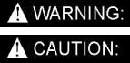
These symbols mean WARNING or CAUTION. Failure to follow warnings and cautions could result in fatality, personal injury to yourself and/or others, or property damage. Follow these instructions carefully!
Read the operator's manual before installing or starting this unit. Failure to adhere to instructions could result in severe personal injury or could be fatal.
Operate this unit and equipment only in a well-ventilated area. Exhaust fumes contain carbon monoxide which is an odorless and deadly poison that can cause severe injury or fatality. DO NOT run this unit in an enclosed area. DO NOT operate this unit where the exhaust may enter any building doorway, window, vent, or opening of any type.
Gasoline is extremely flammable and its vapors can explode if ignited. Store gasoline only in approved containers, in well-ventilated, unoccupied buildings away from sparks or flames. Never carry any gasoline or flammable material in the vehicle. Fumes may accumulate inside the vehicle and ignite, causing an explosion.
DO NOT store any type of flammable material in the vehicle.
This unit must be operated with the vehicle or trailer doors open in order to ensure adequate engine ventilation.
DO NOT operate engine if gasoline is spilled. Avoid creating any ignition until the gasoline has been cleaned up. Never use gasoline as a cleaning agent.
DO NOT place hands, feet, hair, or clothing near rotating or moving parts. Avoid any contact with moving parts! Rotating machinery can cause injury or fatality.
Never operate this unit without belt guards. The high speed moving parts, such as belts and pulleys, should be avoided while this unit is running. Severe injury, damage, or fatality may result.
DO NOT service this unit while it is running. The high-speed mechanical parts as well as high temperature components may result in severe injury or severed limbs.
Never touch electrical wires or components while the engine is running. They can be sources of electrical shock.
Engine components can get extremely hot from operation. To prevent severe burns, DO NOT touch these areas while the engine is running or immediately after the engine is turned off.
DO NOT touch the exhaust diverter valve or any part of the exhaust system while this unit is running. Severe burns may result.
Before servicing this unit, allow it to "cool down." This will prevent burns from occurring.
Water under high pressure at high temperature can cause burns, severe personal injury, or fatality. Shut down machine, allow to cool down, and relieve system of all pressure before removing valves, caps, plugs, fittings, filters, and bolts.
LEGEND SE 980059 07/23/02 |
2-1 |
|
DO NOT leave the vehicle engine running while operating this unit.
Dangerous Acid, Explosive Gases! Batteries contain sulfuric acid. To prevent acid burns, avoid contact with skin, eyes and clothing. Batteries produce explosive hydrogen gas while being charged. To prevent a fire or explosion, charge batteries only in well ventilated areas. Keep sparks, open flames, and other sources of ignition away from the battery at all times. Keep batteries out of the reach of children. Remove all jewelry when servicing batteries.
Before disconnecting the negative (-) ground cable, make sure all switches are OFF. If ON, a spark will occur at the ground cable terminal which could cause an explosion if hydrogen gas or gasoline vapors are present. When disconnecting the battery, ALWAYS disconnect the negative (-) terminal FIRST.
DO NOT smoke around the unit. Gas fumes may accumulate and be ignited. The battery is also extremely flammable. This will prevent possible explosions.
DO NOT damage the vehicle in any manner during installation. When routing fuel lines DO NOT place the hose in any location where damage may occur to the hose or vehicle. Avoid any contact with moving parts, areas of high temperature, brake lines, fuel lines, muffler, catalytic converter, or sharp objects.
DO NOT cut or splice any of the vehicle fuel lines during fuel line installation. This may result in fuel leaks and potentially dangerous conditions. There is no fuel solenoid shut off on this unit. Use only the provided abrasion resistant fuel hose for fuel lines. When traversing the vehicle floor with fuel lines, always use a bulkhead adapter. This will prevent leakage and ensure that the hose is not punctured by vehicle vibration abrasion.
DO NOT exceed your vehicle's weight limit. The console with waste tank and accessories weighs approximately 886 lbs (976 lbs. if mounted on water tank). Make certain that the vehicle has the correct axle rating. This will prevent unsafe vehicle driving conditions.
We require high-back seats on all vehicles in which units are to be installed for head and neck protection. We recommend using a metal partition between the seats and equipment.
DO NOT operate this unit without the water supply attached and turned on. The water pump and other vital components may be seriously damaged if this unit is permitted to operate dry without water. This unit is equipped with a low pressure shutdown device. DO NOT bypass or operate this unit without the low pressure shut-down switch.
Keep your vehicle work area clean. Wands, stair tools, and other accessories must be securely fastened before driving the vehicle.
All high pressure hoses must be rated for 3000 PSI at 250°F. Thermoplastic hoses do not meet these specifications and should not be used. Severe burns and injury may result if the hoses do not meet these requirements.
The winterizing loop hose assembly, Part #10-805380, is for winterizing use only. If used improperly, live steam may escape from this hose, causing it to whip around. Burns or injury may result.
Make certain that you receive complete training by the distributor from whom you purchased this unit.
This unit uses high pressure and temperature. Improper or irresponsible use may result in serious injury.
Do not modify this unit in any manner. Improper modification can cause severe personal injury or fatality.
CALIFORNIA PROPOSITION 65 WARNING: Engine exhaust from this product contains chemicals known to the State of California to cause cancer, birth defects, or other reproductive harm.
2-2 |
LEGEND SE 980059 07/23/02 |
HAZARD INTENSITY LEVEL
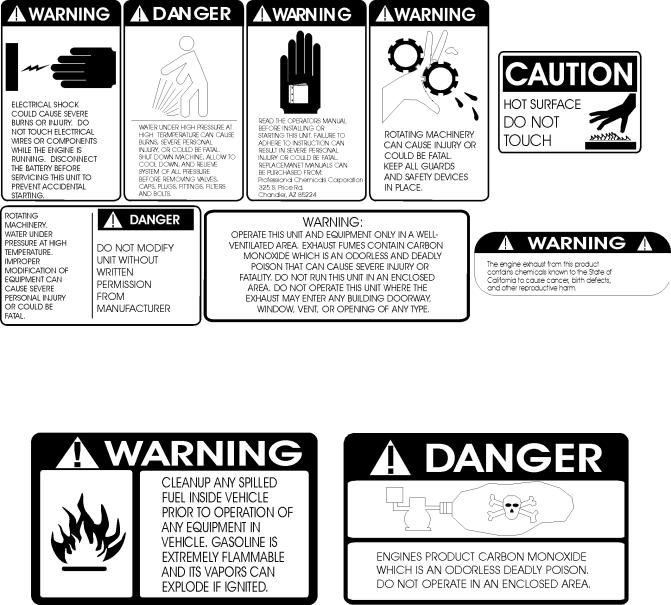
The following WARNING LABELS are found on your LEGEND SE console. These labels point out important Warnings and Cautions which should be followed at all times. Failure to follow warnings and cautions could result in fatality, personal injury to yourself and/or others, or property damage. Follow these instructions carefully! DO NOT remove these labels.
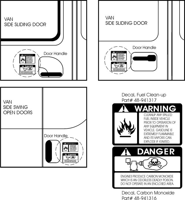
Order Part #48-941212 to get a complete set of decals (safety and instrumentation) for your LEGEND SE cleaning unit. The following decals must be placed in a prominent spot on the vehicle that your unit is to be installed in where access is given to operate the unit. See Figure 12 on page 3-17 for suggested locations for these decals.
Decal, Fuel Clean-Up |
Decal, Carbon Monoxide |
Part #48-941317 |
Part #48-941316 |
LEGEND SE 980059 07/23/02 |
2-3 |
TECHNICAL SPECIFICATIONS
ITEM |
DIMENSION/CAPACITY |
|
Engine speed |
2600 rpm (high speed in H.E. position) |
|
|
1400 rpm (idle speed in Muffler position waster pump OFF. |
|
Water pump rpm |
1395 rpm |
|
Vacuum pump rpm |
3195 rpm |
|
Water flow rate |
3.5 GPM (maximum) |
|
Water pump pressure |
1000 PSI (maximum) |
|
Vacuum relief valve |
13” Hg (13” Legend Hg - SE) |
|
Waste tank capacity |
70 gallons (60 gallons to shut-off) |
|
Console weight |
640 lbs. (730 lbs. If mounted on water tank) |
|
Console weight (with waste tank & accessories) |
886 lbs (976 lbs. If waste tank is full) |
|
|
(1467 lbs. If waste tank is full) |
|
|
(1566 lbs. If auxiliary water tank is full) |
|
TORQUE VALUES |
|
|
Engine hub |
264 inch lbs |
22 foot/lbs |
Vacuum pump hub |
192 inch/lbs |
16 foot/lbs |
JET SIZING:
Prochem recommends floor tool tip sizing not exceed a total of “.045”. Using larger jet sizes on your LEGEND SE may reduce cleaning temperatures.
Example: |
Tri-jet wand uses three 95015 jets (95° spray angle w/ 015 orifice). |
|
|
015 x 3 = 045 |
|
Upholstery tool jet size: |
80015 |
|
Stair tool jet size: |
9502 |
|
3-1 |
LEGEND SE 980059 07/23/02 |
|
DEALER RESPONSIBILITY
The PROCHEM dealer from whom you purchased this mobile cleaning unit is responsible for the correct installation of this machine. The dealer is also responsible for initial training of your operators and maintenance personnel in the proper operation and maintenance of this unit.
ACCEPTANCE OF SHIPMENT
Every part of your Prochem LEGEND SE cleaning unit was carefully checked, tested, and inspected before it left our manufacturing plant. Upon receiving the unit, make the following acceptance check:
1.The unit should not show any outward signs of damage. If damaged, notify the common carrier immediately.
2.Check your equipment and packing list. The standard Prochem LEGEND SE cleaning unit should arrive equipped with the following items (unless otherwise specified) and any optional accessories which were ordered:
EQUIPMENT LIST
1.LEGEND SE console.
2.Operation and service manual with engine, water pump, and vacuum pump manuals.
3.Installation bolting kit.
4.Installation mounting plates.
5.Fittings and hoses for fuel supply installation.
6.Hose clamps for fuel & vacuum hoses.
7.External fuel pump installation kit.
8.Carpet wand.
9.Waste tank w/float switch.
RECEIVING YOUR UNIT
10.Waste tank filter and strainer basket.
11.100 ft. of 2” vacuum hose.
12.1 vacuum hose connector.
13.100 ft. of 1/4" high pressure hose with quick connects.
14.50 ft. water supply hose with quick connect.
15.5 gallon jug and holder.
OPTIONAL EQUIPMENT
15.Winterizing loop hose. Part #10-805380.
16.Upholstery tool and stair tool. #78513/78519 #78521
17.Extra wands.
18.Hose reel. #65-950393
19.Extra vacuum hoses. Part #10-805060.
20.Extra vacuum hose connectors.
Part #12-800078.
21.Extra high pressure water hoses. Part #10-805122.
22.Van storage unit. Part #65-950392.
23.Dual auxiliary water tanks with demand pump. Part #66-945260.
24.H.D Automatic waste pump kit. Part #66945553
25.Galvanized drip tray. Part #56-501845 (Part #56-501930 if mounted on water tank.)
26.Water softener. Part #66-945430.
LEGEND SE 980059 07/23/02 |
3-2 |
|
INSTALLATION
Prior to starting the installation, first read the ENTIRE "Installation” section of this manual. Since the LEGEND SE cleaning unit (with waste tank and accessories) weighs approximately 886 pounds (976 lbs. if mounted on water tank), consider the following recommendations before installing this unit.
1.The unit should NOT be mounted in any motor vehicle of less than 1/2 ton capacity, or 3/4 ton if equipped with one or more auxiliary fresh water tanks.
The console with waste tank and accessories must NOT exceed the vehicle's axle weight limit.
2.If mounting in a trailer, make certain that the trailer is rated for the total weight of the UNIT AND TRAILER. Electric or hydraulic brakes should be provided, and a strict compliance with any State and Federal vehicle laws must be maintained.
3.The vehicle tires should have a load rating above the combined vehicle and unit weight.
4.We do not recommend using flooring materials that absorb water. This could result in rust and corrosion of the vehicle floor.
5.Padding under rubber floor mats should be removed before installing this unit.
6.We highly recommend using a galvanized drip tray under the console (Part #56-501845, or Part #56-501930 for units mounted on a water tank.)
7.If using a trailer, the LEGEND SE console should be positioned so that it balances properly with respect to the axle. Ten percent (10%) of the overall unit weight (without accessories or water) should be on the tongue.
FUEL REQUIREMENTS
Use unleaded gasoline ONLY. DO NOT use any gasoline additives. We recommend the use of clean, fresh, unleaded gasoline intended for automotive use. High octane gasoline should NOT be used with the engine on this unit.
ENGINE OIL REQUIREMENTS
Use high quality detergent oil of at least API (American Petroleum Institute) service class SF or SG. Select the viscosity based on the air temperature at the time of operation as shown in the following table. NOTE: Using less than service class SF or SG oil or extending oil change intervals longer than recommended can cause engine damage.
RECOMMENDED SAE VISCOSITY GRADE
|
|
|
|
|
|
|
|
10W-30 |
|
|
|
|
|
|
5W-20, |
5W-30 |
|
|
|
|
|
|
|
|
|
|
|
|
|
|
|
|
|
|
|
|
|
|
|
|
|
°F -20 |
0 |
20 |
32 40 |
60 |
|
80 |
100 |
||||||
°C -30 |
-20 |
-10 |
|
0 |
|
10 |
20 |
30 |
40 |
||||
TEMPERATURE RANGE EXPECTED BEFORE NEXT OIL CHANGE
3-3 |
LEGEND SE 980059 07/23/02 |
|

CHEMICAL REQUIREMENTS
The Prochem LEGEND SE, due to its chemical injection pump design, can be used with a variety of water-diluted chemical compounds (either acidic or alkaline), depending on the job to be done. However, to obtain optimum results with this unit, we recommend using the Prochem line of chemicals. For information on using the cleaning compounds, refer to the Prochem chemical manual.
WATER REQUIREMENTS
Hard water deposits will adversely affect the plumbing and heat exchange systems on this unit. The map below will give you an idea of where areas of high water hardness may occur. However, any water supply obtained from a well is almost always hard water and a water softener will be needed to protect your equipment.
INSTALLATION
NOTE: Equipment malfunction or component failure caused by hard water scaling is NOT covered under the warranty.
If you are operating this unit in an area where the unit will be using water in which the hardness exceeds 3-1/2 grains, we highly recommend a suitable water softener be installed. If using a water softener, it must have a five (5) GPM (or greater) flow capacity without any hose constrictions.
Using a water softener will reduce maintenance and decrease down time caused by hard water scaling. It will also allow cleaning chemicals to be more effective in lower concentrations.
If you require a water softener, Prochem has a model to meet your needs. Please contact your nearest distributor for information, price, and availability.
LEGEND SE 980059 07/23/02 |
3-4 |
|

INSTALLATION
All units must be bolted to the floor of the vehicle by a PROCHEM DISTRIBUTOR.
LIFTING THE UNIT ONTO THE VEHICLE
Since the Prochem LEGEND SE console weighs approximately 640 lbs. (730 lbs. if mounted on water tank), we recommend using a fork lift to lift the unit onto the vehicle. Position the forks under the unit from the front and make CERTAIN that the forks are spread to the width of the base.
POSITIONING THE UNIT IN THE VEHICLE
Because vehicles vary in size and openings, individuals have their own preference as to where they want their units installed. We strongly recommend a side door installation for the LEGEND SE and DO NOT recommend a rear door installation.
1.Enough space should be provided to assure adequate engine ventilation and room for service and maintenance.
2.The unit with waste tank and accessories must NOT exceed the vehicle's axle weight limit.
3.DO NOT position the console closer than 12" from the bottom of the driver and passenger seats.
NOTE: For individuals who wish to make an engineering layout prior to positioning the unit, refer to Figure 2 for waste tank and console dimensions.
BOLTING DOWN THE UNIT AND WASTE TANK
NOTE: When positioning the waste tank with respect to the console, hook up the vacuum hoses to the waste tank. This will ensure that the waste tank is positioned correctly. Once the unit and waste tank are positioned in the vehicle in the desired location, you may proceed.
Before drilling any mounting holes in the vehicle floor, make certain that when drilling, you will not do any damage to the fuel tank, fuel lines, or any vital component which might affect the operation or safety of the vehicle.
1.Using the console and waste tank mounting holes as a template, drill six 13/32" diameter holes for mounting the console and six more 13/32" diameter holes for mounting the waste tank.
2.Using the installation hardware kit:
a)Insert six 3/8-16 x 2" hex head cap screws with flat washers through the mounting holes in the Prochem LEGEND SE console, and six 3/8-16 x 2" hex head cap screws with flat washers through the mounting holes in the waste tank.
b)Install the mounting plates underneath the vehicle floor.
c)Screw the 3/8-16 hex head locknuts on the mounting screws and tighten them until the console and the waste tank are firmly secured to the vehicle floor.
3-5 |
LEGEND SE 980059 07/23/02 |
|

INSTALLATION
LEGEND SE 980059 07/23/02 |
3-6 |
|
INSTALLATION
WASTE TANK TO CONSOLE
CONNECTION
NOTE: Before connecting any hoses to the waste tanks, make certain the hose clamps are on each hose.
1.See Figure 11. Connect the 12” long section of 2” I.D. internal vac hose to the 2” dia. vac inlet tube on the console and the 2” dia. inlet tube on the waste tank. Tighten the hose clamps.
2.Connect the 25” long section of 2-7/8" I.D. internal vac hose to the 2-7/8” dia. vac outlet tube on the waste tank and to the vacuum pump relief valve on the console. It may be necessary to cut this hose to fit. Tighten the hose clamps.
3.Connect the 2” I.D. waste removal hose to the 2” dia. tube at the bottom of the waste tank. Tighten the hose clamps.
4.Connect the 5/16" I.D. water box hose to the barb fitting (pointed downward) on the waste tank, which is mounted on the outside of the waste tank. Tighten the hose clamps.
5.Connect the console engine shut-off cord to the waste tank level sensor cord.
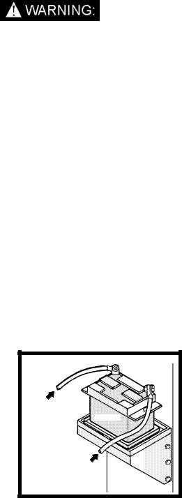
BATTERY CONNECTION
Dangerous Acid, Explosive Gases!
Batteries contain sulfuric acid. To prevent acid burns, avoid contact with skin, eyes, and clothing. Batteries produce explosive hydrogen gas while being charged. To prevent a fire or explosion, charge batteries only in wellventilated areas. Keep sparks, open flames, and other sources of ignition away from the battery at all times. Keep batteries out of the reach of children. Remove all jewelry when servicing batteries.
Before disconnecting the negative (-) ground cable, make sure all switches are OFF. If ON, a spark will occur at the ground cable terminal which could cause an explosion if hydrogen gas or gasoline vapors are present. When disconnecting the battery, ALWAYS disconnect the negative (-) terminal FIRST.
1.Attach the red positive (+) battery cable from the console starter solenoid to the positive (+) terminal on the battery and tighten the holding nut.
2.Next, attach the black negative (-) battery cable from the console ground to the negative (-) terminal on the battery and tighten the holding nut.
BATTERY HOOK-UP
-
+
FROM |
|
GROUND |
|
CONNECTION |
BATTERY |
ON CONSOLE |
|
FROM |
|
STARTER |
|
SOLENOID |
|
ON CONSOLE |
WASTE |
|
TANK |
FIRE EXTINGUISHER
We recommend that a fire extinguisher, preferably rated for A, B, & C type fires, be installed inside the vehicle.
3-7 |
LEGEND SE 980059 06/19/03 |
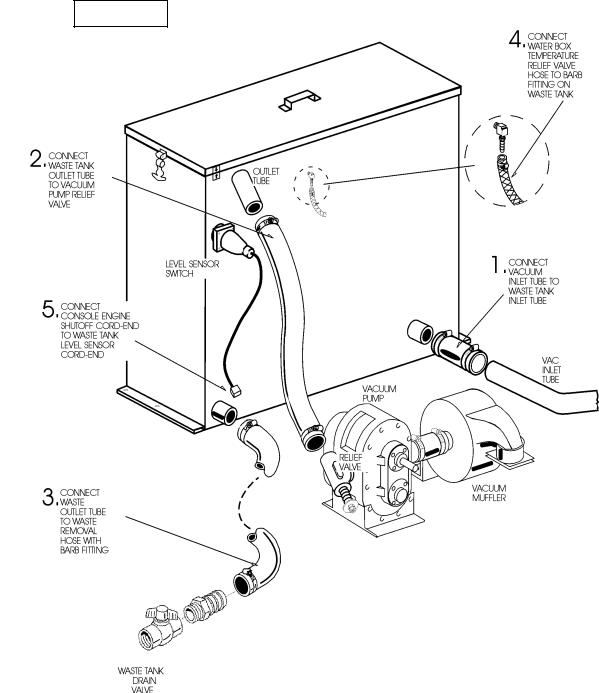
FIGURE 11
SPECIAL INSTRUCTIONS:
1.Cut hoses to fit, if necessary.
2.When cutting hoses, make certain that the cutting blade is facing away from you hands, fingers, or any other part of your body to avoid injury.
INSTALLATION
3.Do not install hoses with excessive bends or kinks.
4.Place clamps on hoses before installing.
5.Tighten all hose clamps firmly.
LEGEND SE 980059 06/19/03 |
3-8 |

INSTALLATION
AUXILIARY WATER TANK CONNECTION
Your cleaning unit may be equipped with an auxiliary water tank mounted underneath the
console. If so, you will need to install the demand pump assembly. (See “Illustrated Parts Listings” for demand pump dimensions.)
The demand pump should be situated in a location where it is easily accessible. We have provided hoses which are long enough to reach their connections on the console and auxiliary water tank.
Figure 12 illustrates how the demand pump works with the auxiliary water tank and how it connects to the console.
1.Connect the ¾” I.D. water hose coming from the in-line strainer on the demand pump to the barb fitting at the bottom rear, right side of the water tank. Trim the hose for the best fit. Tighten the hose clamps.
2.Connect the demand pump cord to the 2-pole connector on the console (located on the left side of the console near the vacuum pump.)
When using the auxiliary water tank as your water source, be sure you have enough water in the tank to complete the job.
1.Connect the hose from the demand pump to the water inlet at the front of the console.
2.Turn the demand pump toggle switch “ON.”
3.See “Operation” section in this manual for instructions on filling the auxiliary water tank.
FIGURE 12
3-9 |
LEGEND SE 980059 06/19/03 |
INSTALLATION
The decals should be placed in a prominent spot on the vehicle where access is given to operate the unit. The illustrations above suggest the location and placement of the decals.
When placing the decals, be sure the area is clean of any dirt and possible wax build-up. Place the decal by starting at on edge and smoothing he decal over to the other edge. This will help eliminate air bubbles and allow the decal to adhere better. After a time the decals may become damaged or worn. If they become unreadable, they should be replace.
LEGEND SE 980059 06/19/03 |
3-10 |
OPERATION
This chapter of the operator’s manual divides the unit up into systems and explains how each system works. Before proceeding into the operation and maintenance sections of this manual, we recommend acquiring a basic knowledge of how this unit functions. Read the next section of this manual carefully and completely.
WATER PUMPING SYSTEM
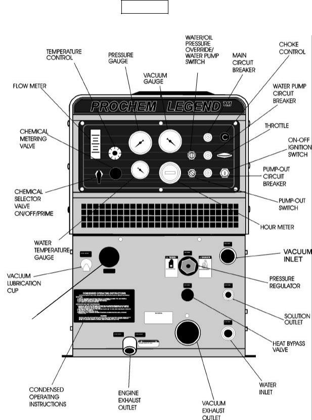
See Figures 14 and 15. Cold water enters the console through the water inlet connection located on the lower front panel. The water flows to the water box through a float valve, which shuts off water flow when the water box is full.
Water then flows from the water box, through a strainer, into the water pump where it is pressurized. This pressurized water is pumped to the pressure regulator manifold where the pressure regulator provides and maintains the desired pressure setting.
The pressure regulator manifold includes a nitrogen charged accumulator which helps reduce pressure pulsation’s. In addition, the manifold also contains a low-pressure switch and a high-pressure switch. These switches will shut the unit down if the water pressure drops below 50 PSI or exceeds 1200 PSI.
If the tool valve is closed, water flows from the pressure regulator through the vacuum exhaust radiator-type heat exchanger, where heat is transferred from the vacuum pump exhaust to the water.
The heated water then returns to the water box. If the temperature in the water box exceeds
180°F, a temperature relief valve will open and bleed a small amount of hot water into the waste tank, allowing cool water to flow into the water box.
When the tool valve is open, water flow is from the pressure regulator to the engine exhaust heat exchanger, where the water is super-heated by engine exhaust.
A bypass manifold, located next to the water box, constantly bleeds a small amount of hot water from the engine exhaust heat exchanger outlet to the water box.
Next, the hot water flows through the check valve manifold which contains a check valve and Y-strainer. This is where chemical injection occurs.
The hot solution then flows through the solution outlet manifold to the cleaning tool.
Temperature is adjusted primarily using the thermostatic temperature control. This control opens a solenoid valve if the water exceeds the temperature setting. When open, this valve allows hot water to be drawn into the waste tank. The temperature sensor for this control is located in the thermostat manifold en route to the solution outlet.
In addition, a heat bypass valve on the lower front panel lowers the solution temperature manually with a knob adjustment. When open, this valve allows hot water to be drawn into the waste tank.
An additional temperature sensor on the engine exhaust heat exchanger outlet will shut down the engine if the water temperature exceeds 285°F. If this occurs, consult the “Trouble-shooting” section of this manual to determine the cause of overheating before restarting your unit.
3-11 |
LEGEND SE 980059 06/19/03 |
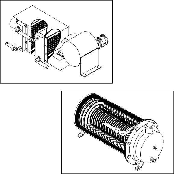
HEAT TRANSFER SYSTEM
See Figures 14 and 15. Water is heated through a two stage heat exchange system which uses vacuum pump exhaust and engine exhaust.
Stage one utilizes vacuum exhaust heat blowing over a radiator-type heat exchanger prior to discharging the exhaust into the atmosphere. When the tool valve is closed, the water bypasses from the pressure regulator manifold back to the water box through the vacuum exhaust heat exchanger. The water is heated as it flows through this heat exchanger.
OPERATION
When the tool valve is open, the water flows from the pressure regulator manifold and through the stage two engine exhaust heat exchanger system where it is super-heated by extremely hot engine exhaust.
The engine exhaust heat exchanger is an engine exhaust chamber containing a stainless steel heating coil and catalytic converter. Water flows through the coil and is heated by the engine exhaust as is leaves the engine. The catalytic converter, combined with the injection of air pumped into the exhaust manifold, re-burns the exhaust waste gases. This results in super-heated water flowing through the solution outlet to the cleaning tool.
VACUUM EXHAUST
HEAT EXCHANGER
CATALYTIC
ENGINE EXHAUST
HEAT EXCHANGER
LEGEND SE 980059 06/19/03 |
3-12 |
OPERATION
FIGURE 14
3-13 |
LEGEND SE 980059 06/19/03 |

OPERATION
FIGURE 15
LEGEND SE 980059 06/19/03 |
3-14 |

OPERATION
VACUUM SYSTEM
An exhaust diverter valve is located on the engine exhaust system. This directs the exhaust either to the heat exchanger for high temperature cleaning or to the exhaust muffler for low temperature cleaning or extraction, such as for flood restoration.
When the diverter valve is in the MUFFLER position, a relay automatically shuts off the water pump. An override switch on the control panel will enable you to turn the water pump ON, for low temperature cleaning.
See Figure 16. Vacuum flow is initiated by the vacuum pump, with air and water being drawn into the vacuum inlet at the front of the con-sole.
The mixture then flows through a strainer basket into the waste tank. Air exits the waste tank through a 100-mesh filter, and then flows into the vacuum pump. A vacuum pump relief valve has been provided for vacuum pump protection.
FIGURE 16
The air is discharged from the vacuum pump through the stage one heat exchanger where the heated vacuum exhaust blows across a radiatortype heat exchanger before discharging into the atmosphere.
A level sensor switch located near the top of the waste tank will shut the unit down before the waste tank reaches its full capacity. This protects the vacuum pump from water damage.
Use of a DEFOAMER will help prevent damage to the unit by a build-up of foam in the waste tank, which may be caused by some chemicals (foam build-up will not activate float switches).
3-15 |
LEGEND SE 980059 06/19/03 |

CHEMICAL PUMPING SYSTEM
See Figure 17. The chemical is drawn from the chemical container through a strainer into the flow meter. The flow meter indicates the rate of chemical flow.
The chemical then flows through a check valve into a pulse-powered chemical pump. Next, the chemical pump injects the chemical through a check valve to the 3-way selector valve on the control panel. This valve may turn the chemical flow ON, OFF, or PRIME the chemical pump
FIGURE 17
OPERATION
The chemical then flows through a metering valve to the solution outlet. This valve controls the rate of flow of chemical injection into the cleaning solution, which is indicated on the flow meter.
LEGEND SE 980059 06/19/03 |
3-16 |

OPERATION
Operate this unit and equipment only in a wellventilated area. Exhaust fumes contain carbon monoxide which is an odorless and deadly poison that can cause severe injury or fatality. DO NOT operate this unit where the exhaust may enter any building doorway, window, vent, or opening of any type.
CHECK FOR ADEQUATE FUEL
Check the fuel tank to be certain there is adequate fuel to complete the job. This unit uses approximately .95 to 1.25 gallons of fuel per hour, depending on the speed setting.
REMOVE TOOLS FROM VEHICLE
Remove any tools or hoses from the van which you will require.
WATER SUPPLY CONNECTION
NOTE: Before connecting your water hose to the supply faucet, flush out the faucet until the water is free of any debris. Flush out any debris which may be in your water inlet hose.
1.Connect the water supply hose to the water inlet quick-connect at the front of the unit. Connect the hose to the water supply faucet.
NOTE: Never use your waste pump outlet hose as a water inlet hose. Use only clean hoses for water inlet.
2.Turn the water supply faucet on. The water will fill the water box.
FILLING AUXILIARY WATER TANK
1.Your cleaning unit may be equipped with an auxiliary water tank mounted underneath the console. To fill the auxiliary water tank, open the ball valve on the water box by turning the handle on the valve to the vertical position.
2.Connect the water supply hose to the water inlet quick-connect at the front of the unit. Connect the hose to the water supply faucet.
3.Turn the water supply faucet on. The water will flow through the water box and fill the auxiliary water tank.
4.When the auxiliary water tank is full, close the ball valve on the water box by turning the handle on the valve to the horizontal position. Disconnect the water supply hose from the unit and plug the hose from the demand pump into the water inlet quick-connect at the front of the unit.
5.Turn ON the toggle switch at the front of the demand pump.
NOTE: Make sure you turn on the demand pump before you start the unit.
3-17 |
LEGEND SE 980059 06/19/03 |
OPERATION
FIGURE 18
EXHAUST
DIVERTER
SOLENOID ROTARY
LEGEND SE 980059 06/19/03 |
3-18 |

OPERATION
HIGH PRESSURE HOSE
Before starting the unit, connect the pressure hose to the solution outlet connection at the
front of the unit. Connect the cleaning tool to the pressure hose .


 DANGER
WATER UNDER HIGH PRESSURE AT HIGH TEMPERATURE CAN CAUSE BURNS, SEVERE PERSONAL INJURY, OR COULD BE FATAL. SHUT DOWN MACHINE, ALLOW TO COOL DOWN, AND RELIEVE SYSTEM OF ALL PRESSURE BEFORE REMOVING VALVES, CAPS, PLUGS, FITTINGS, FILTERS AND BOLTS.
ROTATING |
DANGER |
|
MACHINERY. |
||
WATER UNDER |
|
|
PRESSURE AT HIGH |
DO NOT MODIFY |
|
TEMPERATURE. |
||
IMPROPER |
UNIT WITHOUT |
|
MODIFICATION OF |
WRITTEN |
|
EQUIPTMENT CAN |
PERMISSION |
|
CAUSE SEVERE |
||
FROM |
||
PERSONAL INJURY |
||
OR COULD BE |
MANUFACTURER |
|
FATAL. |
|
|
|
|
VACUUM HOSE
Connect the vacuum hose to the vacuum inlet connection at the front of the unit. Connect the other end of the vacuum hose to the cleaning tool.
STARTING THE UNIT
1.For carpet and upholstery cleaning set the temperature control on the control panel to the desired cleaning temperature. The thermostatic temperature control will allow you to increase or decrease the solution temperature automatically. Simply turn the control knob to the desired temperature setting.
2.For flood extraction operations set temperature control to 50°. This temperature setting energizes the rotary solenoid to hold the Exhaust Diverter in muffler position.
3.Close the heat bypass valve by turning the knob clockwise. DO NOT over-tighten.
The heat bypass valve allows you to decrease the solution temperature manually. Opening the valve (counter-clockwise) decreases the temperature by allowing hot water to bypass to the waste tank.
Before proceeding, be certain that the control panel indicators are at the following settings:
Engine – IDLE (Throttle Control In)
Engine Choke – PULL OUT
NOTE: It will not be necessary to pull the choke out if the engine is already warmed up.
4.Turn the ignition switch to the START position while holding the water pump switch to the left (override position). The engine will start.
For cleaning operation turn pump switch clockwise to on position. For flood extraction operations leave switch in off or straight up position.
NOTE: If your unit fails to build water pressure after 15 seconds, check for adequate water supply. If necessary, see “Loss of Water Pump Pressure” in the “Troubleshooting” section of this manual.
5.After starting the engine, push the choke in. After the engine has warmed up, pull the throttle all the way out and lock it in the full throttle position.
Allow adequate time for the unit to warm up before beginning the cleaning operation, approximately 5-15 minutes.
3-19 |
LEGEND SE 980059 06/19/03 |

PRIMING THE CHEMICAL PUMP
NOTE: Prochem recommends that the chemical pump be primed whenever the water pump is ON. This will eliminate possible pressure fluctuations and water pump pulsation’s related to a dry chemical pump.
1.Place the chemical inlet tube and the chemical prime tube into the chemical container.
NOTE: When placing the chemical inlet tube into the chemical container, make certain that it stays fully submerged since the chemical pump will not function if air is allowed to enter the inlet line. DO NOT operate the chemical pump without the inlet strainer properly installed.
2.Turn the chemical selector valve on the control panel to the PRIME position. The chemical will then flow from the chemical container through the chemical prime tube.
If the chemical does not flow, then:
a.Put the chemical prime tube into the vacuum inlet on the unit and seal off the vacuum inlet. The vacuum will quickly pull chemical from the chemical container. When the chemical starts to flow, turn the chemical selector valve to OFF, place the chemical prime tube back into the container, and turn the chemical selector valve back to PRIME to continue the procedure.
b.Once continuous chemical flow without air bubbles has been achieved, turn the chemical selector valve from PRIME to METER. With the cleaning tool open, observe the flow meter and adjust the chemical metering valve until the desired rate of chemical flow is obtained (the chemical metering valve is located on the control panel below the temperature control.)
WASTE PUMP
1.If your unit is equipped with an automatic waste pump, connect one end of a garden hose to the pump-out connection on the console and the other end to an appropriate waste disposal.
OPERATION
2.Turn the pump-out switch on the control panel to the ON position. The waste pump will operate automatically throughout the cleaning operation.
We recommend that you use a 3/4" I.D. water hose as a waste pump outlet hose. DO NOT use a hose smaller than 5/8" I.D.
NEVER use your automatic waste pump outlet hose as a water inlet hose.
NEVER dispose of waste in storm drains, water ways, or on ground areas. Always dispose of waste in accordance with Local, State, and Federal laws.
OPERATION
Once you have completed steps 1 through 10, proceed with the cleaning operation. Your unit should be in the full throttle position when cleaning or extracting. A float switch located inside the waste tank will automatically shut down the unit when it reaches its full capacity. When this occurs, empty the waste tank before continuing.
EXHAUST DIVERTER VALVE
The automatic exhaust diverter valve directs exhaust through either:
a.The high temperature heat exchanger or through the muffler. This is fully automatic and is controlled through the temperature setting dial for cleaning operations.
b.Set temperature control to desired temperature or for flood extraction set to 50°.
LEGEND SE 980059 06/19/03 |
3-20 |

OPERATION
CLEANING
Observe the following guidelines, while cleaning:
1.Before proceeding make sure the nozzles are functioning properly.
a)To check, hold the wand about one foot above the surface to be cleaned and open the wand valve. A full spray should be observed from the cleaning nozzles.
b)If the nozzles are not showing a full spray pattern, adjust nozzles for proper pattern, clean, or replace nozzles, if required.
2.Normally, chemical is applied on the push stroke of the wand when cleaning, and vacuuming is done on the pull stroke. For heavily soiled carpets the wand may be used in a scrubbing manner, applying chemical in both push and pull strokes. Always finish up an area with a vacuum pull stroke.
3.When cleaning, keep the working opening (mouth) flat on the surface being cleaned. Keep the wand moving when the valve is open.
4.The unit will automatically shut-down when the waste tank is full. This will prevent water being drawn into the vacuum pump. If shut-down occurs, empty the waste tank before proceeding.
NEVER dispose of waste in storm drains, waterways, or onto the ground. Always dispose of waste in accordance with Local, State, and Federal laws.
UPHOLSTERY CLEANING
Upholstery Tool, Part #78513
1.Set temperature as desired and slow down engine speed to minimize excess heat.
2.Slow engine speed down to minimize excess heat.
3.Use one (1) "80015" spray tip in the tool.
4.Pressure adjustment below 300 PSI should be made at the tool itself, by using the adjusting knob located on the valve.
STAIR TOOL CLEANING
Stair Tool, Long, Part #78519
Stair Tool, Short, Part #78521
1.Set temperature as desired and slow down engine speed to minimize excess heat.
2.Slow engine speed down to minimize excess heat.
3.Use one (1) "9502" spray tip in your stair tool.
3-21 |
LEGEND SE 980059 06/19/03 |

OPERATION
FLOOD RESTORATION
Set the temperature control on the control panel to 50°.
SHUTDOWN AND DAILY MAINTENANCE
1.Run fresh water through the chemical injection system to flush out chemicals.
2.We recommend removing as much moisture from your vacuum hoses as is reasonable. This will prevent spillage of solution in your vehicle when replacing hoses.
3.Position the throttle control to about 3/4 of the way out, but no less than 1/2 of the way out.
4.Disconnect the vacuum hosesfrom the unit.
5.Set temperature dial to 50°, and allow the unit to cool down to 180°F or less.
6.Push the throttle all the way in to idle and allow the unit to run for 1 minute in order to remove all moisture from the vacuum pump.
NOTE: If finishing for the day: Pull the throttle all the way out, plug the vacuum inlet and spray WD40 (or equivalent) into the vacuum lubrication cup (located at front of console) for 5 seconds. This will lubricate the vacuum pump. Pull the throttle back to idle and continue to step #7.
7.Turn the ignition switch to the OFF position.
8.Turn the water supply faucet off. Bleed the pressure out of the water supply hose by loosening the hose at the water supply. Unhook the water supply hose and store in vehicle.
9.Relieve pressure from the cleaning tools and pressure hoses by activating the valve on the tools. Disconnect the tools and pressure hoses from the unit and store all items.
10.Drain the waste tank and dispose of waste in a proper manner.
NEVER dispose of waste in storm drains, water ways, or on ground areas. Always dispose of waste in accordance with Local, State, and Federal laws.
11.Remove the strainer basket from the waste tank, clean out any accumulated debris, and reinstall. Inspect the vacuum inlet filter inside the waste tank. If there is any lint or debris, remove and clean filter.
NOTE: When removing the vacuum inlet filter, grip the plastic hexagonal section of filter. Grasping filter by the screen may collapse or ruin the filter. Re-install the filter hand-tight. NEVER operate this unit with this filter removed, damaged or improperly installed.
NOTE: When replacing this filter, we recommend using the stainless steel Prochem filter,
Part #14-806518, only.
12.At the end of your work day, rinse out the waste tank with fresh water. DUO Deodorizer may be added to the waste tank to inhibit the growth of bacteria.
13.Clean the unit, tools, hoses, van interior, etc., as needed. Inspect ALL equipment for any damage, wear, leaks, etc.
LEGEND SE 980059 06/19/03 |
3-22 |
 Loading...