


Operating Instructions (ENG)
MODELS: EVEREST EFI LP
EVEREST EFI HP
Read instructions before operating the machine.
AG 98019712/27/06

MODEL _______________________________________
DATE OF PURCHASE __________________________
SERIAL NUMBER ______________________________
SALES REPRESENTATIVE # _____________________
YOUR DEALER
NAME: _________________________________________________________________________________________________
ADDRESS: _______________________________________________________________________________________________
PHONE NUMBER: _________________________________________________________________________________________
Welcome…and congratulations on the purchase of your Mobile Cleaning Unit. This instruction manual is a guide for operating and servicing your unit. Read this manual completely before installing or operating this unit.
This unit offers you personal convenience. All of your instrumentation and controls have been positioned to give you easy access for operation and daily maintenance.
Proper operation and service are essential to the efficient functioning of this unit. When maintained correctly, this unit will have a long, trouble-free life.
The service methods described in this manual are explained in such a manner that servicing may be performed accurately and safely. Proper service varies with the choice of procedure, the skill of the mechanic, and the tools or parts available. Before attempting any repair, make certain that you are thoroughly familiar with this equipment and are equipped with the proper tools. Any questions pertaining to operating or servicing this unit should be directed to your nearest dealer.
THIS UNIT MUST BE INSTALLED BY THE DEALER FROM WHOM YOU PURCHASED IT IN ACCORDANCE WITH THE PRESCRIBED INSTALLATION PROCEDURES.
MAKE CERTAIN THAT THE WARRANTY CARD IS FILLED OUT AT THE TIME OF INSTALLATION AND IS RETURNED TO YOUR DEALER.
PROFESSIONAL CHEMICALS CORPORATION 325 SOUTH PRICE ROAD
CHANDLER, ARIZONA 85224
Information in this document is subject to change without notice and does not represent a commitment on the part of Professional Chemicals Corporation.
EVEREST EFI 980197 06/30/04 |
1 |
TABLE OF CONTENTS
Machine Data Log/Overview......................... |
1 |
Table of Contents ......................................... |
2 |
Receiving Your Unit ...................................... |
4 |
HOW TO USE THIS MANUAL |
|
How to use this Manual. ............................... |
1-1 |
SAFETY |
|
Safety Instructions ....................................... |
2-1 |
Hazard Intensity Level .................................. |
2-3 |
OPERATION & SYSTEMS |
|
Technical Specifications. .............................. |
3-1 |
Installation Requirements ............................. |
3-2 |
Fuel Requirements ....................................... |
3-2 |
Engine Oil Requirements.............................. |
3-2 |
Electronic Fuel Injection System................... |
3-3 |
Emission Control Information........................ |
3-3 |
Date Stamp Location .................................... |
3-4 |
Fuel Pump and Filter .................................... |
3-4 |
Error Codes .................................................. |
3-5 |
Zenith Distributor Locations .......................... |
3-6 |
Chemicals & Water....................................... |
3-7 |
Components ............................................... |
3-8 |
Water Pumping and Heat Transfer ............. |
3-12 |
Chemical Injection System ......................... |
3-15 |
Vacuum System.......................................... |
3-16 |
Pre-run Inspections..................................... |
3-17 |
Priming the Chemical Pump ....................... |
3-18 |
Waste Pump ............................................... |
3-18 |
Cleaning...................................................... |
3-18 |
Upholstery Cleaning ................................... |
3-19 |
Shutdown and Daily Maintenance (LP) ...... |
3-19 |
High Pressure System ................................ |
3-19 |
High Pressure Shutdown & |
|
Return to Low Pressure .............................. |
3-20 |
De-flooding Operations............................... |
3-20 |
Freezing Protection..................................... |
3-20 |
Winterizing Your Unit .................................. |
3-21 |
Removing Anti-freeze from Unit.................. |
3-22 |
MAINTENANCE & SERVICE
Maintenance |
|
Maintenance Schedule ........................... |
4-1 |
Key Maintenance Checkpoints ............... |
4-3 |
Engine..................................................... |
4-4 |
Vacuum Pump ........................................ |
4-5 |
Water Pump ............................................ |
4-6 |
Vacuum Inlet Filter .................................. |
4-6 |
Vacuum Relief Valve............................... |
4-6 |
Vacuum Drive Belts, Pulleys And Hubs .. |
4-6 |
Water Pump Drive Belt ........................... |
4-7 |
Float Valve (Water Box).......................... |
4-7 |
Waste Tank Strainer Basket ................... |
4-7 |
Y-Strainer (Outlet)................................... |
4-7 |
Temperature Balance Orifice .................. |
4-7 |
Check Valve (Outlet)............................... |
4-7 |
Chemical Pump....................................... |
4-7 |
Nitrogen Accumulator ............................. |
4-8 |
Pressure Regulator ................................. |
4-8 |
Vacuum Hoses........................................ |
4-8 |
Pressure Hoses ...................................... |
4-8 |
Chemical Simulator Valve....................... |
4-7 |
Optional Waste Pump-out....................... |
4-8 |
Engine Coolant Replacement ................. |
4-8 |
General Service Adjustments |
|
Check Valve (Solution Outlet)................. |
4-9 |
Chemical Pump....................................... |
4-9 |
Packing Nut Adjustment |
|
(Chemical Metering & Selector Valves) .. |
4-10 |
Pressure Regulator ................................. |
4-10 |
Troubleshooting ...................................... |
4-11 |
2 |
EVEREST EFI 980197 06/30/04 |
TABLE OF CONTENTS
PARTS LIST
Framework .................................................. |
5-1 |
Side Panel, Right ........................................ |
5-5 |
Side Panel, Left........................................... |
5-7 |
Chemical Panel........................................... |
5-9 |
Control Panel .............................................. |
5-11 |
Engine......................................................... |
5-13 |
Engine Coolant ........................................... |
5-19 |
Vacuum Blower........................................... |
5-21 |
Water Pump-PP .......................................... |
5-23 |
Water Pump-PPHP ..................................... |
5-25 |
Vacuum/Heat Exchanger And Silencer....... |
5-29 |
Solution Temperature Control Valve........... |
5-31 |
Heli-Coil Heat Exchanger............................ |
5-33 |
Solution Outlet ............................................ |
5-35 |
Water Box-PP ............................................ |
5-37 |
Water Box-PPHP ........................................ |
5-39 |
Pressure Regulator-PP ............................... |
5-41 |
Pressure Regulator-PPHP .......................... |
5-43 |
Waste Tank –80 Gal. & 100 Gal ................. |
5-45 |
Hose Accessories ....................................... |
5-47 |
Battery-Floor Mount .................................... |
5-49 |
Automatic Pumpout (Optional).................... |
5-51 |
WandTitanium Six Jet (Optional) .............. |
5-55 |
Wand - Quad-Jet (Optional)........................ |
5-57 |
Wand – Tri-Jet (Optional)............................ |
5-59 |
Stair Tool (Optional).................................... |
5-61 |
Upholstery Tool (Optional) .......................... |
5-63 |
Shelf Assembly (Optional) .......................... |
5-65 |
Water Tank, Dual With |
|
Demand Pump (Optional) ........................... |
5-67 |
Water Tank-Demand Pump (Optional) ....... |
5-69 |
Hose Reel (Optional) .................................. |
5-71 |
Wiring Diagram ........................................... |
5-73 |
Hose Diagram-PP ....................................... |
5-74 |
Hose Diagram-PPHP .................................. |
5-75 |
Warranty ..................................................... |
5-76 |
EVEREST EFI 980197 06/30/04 |
3 |
RECEIVING YOUR UNIT
ACCEPTANCE OF SHIPMENT
Every part of your cleaning unit was carefully checked, tested, and inspected before it left our manufacturing plant. Upon receiving the unit, make the following acceptance check:
1.The unit should not show any outward signs of damage. If damaged, notify the delivering carrier immediately.
2.Check your equipment and packing list. The cleaning unit should arrive equipped with the following items (unless otherwise specified).
NOTE: Your distributor from whom you purchased this mobile cleaning unit is responsible for the correct installation of this machine. The dealer is also responsible for initial training of your operators and maintenance personnel in the proper operation and maintenance of this unit.
EQUIPMENT LIST:
1.Console.
2.Waste tank
3.Hose clamps for vacuum hoses.
4.150 ft. of 2” vacuum hose.
5.2 vacuum hose connectors.
6.150 ft. of 1/4" high pressure hose with quick connects.
7.50 ft. water supply hose with quick connect.
8.Installation bolting kit.
9.Installation mounting plates.
10.Operation and service manual for engine, water pump, and vacuum pump manuals.
11.Fuel Pump Assembly and Power Cord.
4 |
EVEREST EFI 980197 06/30/04 |
This manual contains the following sections:
-HOW TO USE THIS MANUAL
-SAFETY
-INSTALLATION REQUIREMENTS
-SYSTEMS
-OPERATIONS
-MAINTENANCE & SERVICE
-PARTS LIST
The HOW TO USE THIS MANUAL section will tell you how to find important information for ordering correct repair parts.
Parts may be ordered from authorized dealers. When placing an order for parts, the machine model and machine serial number are important. Refer to the MACHINE DATA box which is filled out during the installation of your machine. The MACHINE DATA
box is located on the inside of the front cover of this manual.
MODEL _____________________________________
DATE OF PURCHASE ________________________
SERIAL NUMBER ____________________________
SALES REPRESENTATIVE # ___________________
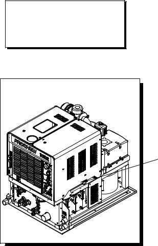
The model and serial number of your machine is on
the side approximately where shown.
HOW TO USE THIS MANUAL
The SAFETY section contains important information regarding hazard or unsafe practices of the machine. Levels of hazards is identified that could result in product or personal injury, or severe injury resulting in death.
The OPERATIONS section is to familiarize the operator with the operation and function of the machine.
The MAINTENANCE section contains preventive maintenance to keep the machine and its components in good working condition. They are listed in this general order:
-Engine
-Vacuum Pump
-Water Pump
-Drive Belts, Pulleys & Hubs
-Chemical Pumps
-Hoses
-Vac/Exhaust Heat Exchanger
-General Service Adjustments
-Troubleshooting
The PARTS LIST section contains assembled parts illustrations and corresponding parts list. The parts lists include a number of columns of information:
-REF – column refers to the reference number on the parts illustration.
-PART NO. – column lists the part number for the part.
-DESCRIPTION – column is a brief description of the part.
-SERIAL NO. FROM – column indicates the first machine the part number is applicable to. When the machine design has changed, this column will indicate serial number of applicable machine. The main illustration shows the most current design of the machine. The boxed illustrations show older designs. If column has an asterisk (*), call manufacturer for serial number.
-NOTES – column for information not noted by the other columns.
NOTE: If a service or option kit is installed on your machine, be sure to keep the KIT INSTRUCTIONS which came with the kit. It contains replacement parts numbers needed for ordering future parts.
NOTE: The 98# on the lower left corner of the front cover is the part number for this manual.
EVEREST EFT 980197 07/22/04 |
1-1 |

IMPORTANT SAFETY INSTRUCTIONS
When using this machine, basic precautions must always be followed, including the following:
READ ALL INSTRUCTIONS BEFORE USING THIS MACHINE.
These symbols mean WARNING or CAUTION. Failure to follow warnings and cautions could result in fatality, personal injury to yourself and/or others, or property damage. Follow these instructions carefully!
Read the operator's manual before installing or starting this unit. Failure to adhere to instructions could result in severe personal injury or could be fatal.
Operate this unit and equipment only in a well-ventilated area. Exhaust fumes contain carbon monoxide which is an odorless and deadly poison that can cause severe injury or fatality. DO NOT run this unit in an enclosed area. DO NOT operate this unit where the exhaust may enter any building doorway, window, vent, or opening of any type.
Gasoline is extremely flammable and its vapors can explode if ignited. Store gasoline only in approved containers, in well-ventilated, unoccupied buildings away from sparks or flames. Never carry any gasoline or flammable material in the vehicle. Fumes may accumulate inside the vehicle and ignite, causing an explosion.
DO NOT store any type of flammable material in the vehicle.
This unit must be operated with the vehicle or trailer doors open in order to ensure adequate engine ventilation.
DO NOT operate engine if gasoline is spilled. Avoid creating any ignition source until the gasoline has been cleaned up. Never use gasoline as a cleaning agent.
DO NOT place hands, feet, hair, or clothing near rotating or moving parts. Avoid any contact with moving parts! Rotating machinery can cause injury or fatality.
Never operate this unit without belt guards or heat guards. The high speed moving parts, such as belts and pulleys, should be avoided while this unit is running. Severe injury, damage, or fatality may result.
DO NOT service this unit while it is running. The high-speed mechanical parts as well as high temperature components may result in severe injury or severed limbs.
Never touch electrical wires or components while the engine is running. They can be sources of electrical shock.
Engine components can get extremely hot from operation. To prevent severe burns, DO NOT touch these areas while the engine is running - or immediately after the engine is turned off.
DO NOT touch the exhaust system while this unit is running. Severe burns may result.
Before servicing this unit, allow it to "cool down." This will prevent burns from occurring.
Water under high pressure at high temperature can cause burns, severe personal injury, or fatality. Shut down machine, allow to cool down, and relieve system of all pressure before removing valves, caps, plugs, fittings, filters, and bolts.
2-1 |
EVEREST EFT 980197 06/30/04 |
DO NOT leave the vehicle engine running while operating this unit.
Dangerous Acid, Explosive Gases! Batteries contain sulfuric acid. To prevent acid burns, avoid contact with skin, eyes and clothing. Batteries produce explosive hydrogen gas while being charged. To prevent a fire or explosion, charge batteries only in well ventilated areas. Keep sparks, open flames, and other sources of ignition away from the battery at all times. Keep batteries out of the reach of children. Remove all jewelry when servicing batteries.
Before disconnecting the negative (-) ground cable, make sure all switches are OFF. If ON, a spark will occur at the ground cable terminal which could cause an explosion if hydrogen gas or gasoline vapors are present. When disconnecting the battery, ALWAYS disconnect the negative (-) terminal FIRST.
DO NOT smoke around the unit. Gas fumes may accumulate and be ignited. The battery is also extremely flammable. This will prevent possible explosions.
DO NOT damage the vehicle in any manner during installation. When routing fuel lines DO NOT place the hose in any location where damage may occur to the hose or vehicle. Avoid any contact with moving parts, areas of high temperature, brake lines, fuel lines, muffler, catalytic converter, or sharp objects.
DO NOT cut or splice any of the vehicle fuel lines during fuel line installation. This may result in fuel leaks and potentially dangerous conditions. There is no fuel solenoid shut off on this unit. Use only the provided fuel hose for fuel lines. When traversing the vehicle floor with fuel lines, always use a bulkhead adapter. This will prevent leakage and ensure that the hose is not punctured by vehicle vibration abrasion.
DO NOT exceed your vehicle's weight limit. The console with waste tank and accessories weighs approximately 1840 lbs. Make certain to account for any additional accessories in your weight and balance calculations. Make certain that the vehicle has the correct axle rating. This will prevent unsafe vehicle driving conditions.
We require high-back seats on all vehicles in which units are to be installed for head and neck protection.
We recommend using a metal partition between the seats and equipment.
DO NOT operate this unit without the water supply attached and turned on. The water pump and other vital components may be seriously damaged if this unit is permitted to operate dry without water.
DO NOT operate this unit without the filter installed in the waste tank.
Keep your vehicle work area clean. Wands, stair tools, and other accessories must be securely fastened before driving the vehicle.
All pressure hoses must be rated for 3000 PSI at 250°F. Thermoplastic hoses do not meet these specifications and should not be used. Severe burns and injury may result if the hoses do not meet these requirements.
The winterizing loop hose assembly, Part #10-805380, is for winterizing use only. If used improperly, live steam may escape from this hose, causing it to whip around. Burns or injury may result.
Make certain that you receive complete training by the distributor from whom you purchased this unit. This unit uses high pressure and temperature. Improper or irresponsible use may result in serious injury. Do not modify this unit in any manner. Improper modification can cause severe personal injury or fatality.
CALIFORNIA PROPOSITION 65 WARNING: Engine exhaust from this product contains chemicals known to the State of California to cause cancer, birth defects, or other reproductive harm.
EVEREST EFI 980197 06/30/04 |
2-2 |

HAZARD INTENSITY LEVEL
The following WARNING LABELS are found on your cleaning unit . These labels point out important Warnings and Cautions which should be followed at all times. Failure to follow warnings and cautions could result in fatality, personal injury to yourself and/or others, or property damage. Follow these instructions carefully! DO NOT remove these labels.
NOTE: If at any time the labels become illegible, promptly replace them.
Caution label Part # 500707
Front panel decal-PPHP Part # 790819
SOLUTION |
LOW PRESSURE |
TEMPERATURE |
CHEMICAL |
SOLUTION REGULATOR |
BALANCE ORIFICE |
CHECK VALVE |
|
PRESSURE |
|
|
|
HIGH PRESSURE |
|
|
|
1000-3000 PSI |
|
|
|
WARM |
SOLUTION TEMPERATURE |
HOT |
|
CONTROL VALVE |
|
CONDENSED OPERATING INSTRUCTIONS
STARTING
LOW PRESSURE
SOLUTION SCREEN
HIGH PRESSURE |
HIGH PRESSURE |
SHUTDOWN AND DAILY MAINTENANCE |
SOLUTION REGULATOR |
SOLUTION OUTLET |
|
LOW PRESSURE
SOLUTION OUTLETS
CARPET AND
UPHOLSTERY
LOW PRESSURE SOLUTION
50-1000 PSI
Caution Tag
Part # 500706
Front panel decal-PP Part # 790820
SOLUTION PRESSURE |
TEMPERATURE |
CHEMICAL |
REGULATOR |
BALANCE ORIFICE |
CHECK VALVE |
WARM |
SOLUTION TEMPERATURE |
HOT |
|
CONTROL VALVE |
|
CONDENSED OPERATING INSTRUCTIONS |
|
|
STARTING |
|
|
SOLUTION SCREEN |
|
|
SHUTDOWN AND DAILY MAINTENANCE |
|
|
SOLUTION OUTLETS |
|
|
CARPET AND |
|
|
UPHOLSTERY |
|
|
SOLUTION |
|
|
Warning label Part # 500769
Caution label Part # 500770
2-3 |
EVEREST EFI 980197 08/16/04 |
|
|
OPERATIONS |
TECHNICAL SPECIFICATIONS |
|
|
ITEM |
DIMENSION/CAPACITY |
|
Engine speed |
2200 rpm (medium speed) Water Pump ON |
|
|
900 rpm (idle speed) Water Pump OFF. |
|
Water pump rpm |
1455 rpm |
|
Vacuum pump rpm |
3400 rpm |
|
Water flow rate |
4.5 GPM (maximum) |
|
Water pump pressure (low pressure) |
1000 PSI (maximum) |
|
Water pump pressure (high pressure) |
3000 PSI (maximum) |
|
Vacuum relief valve |
13” Hg |
|
Waste tank capacity |
80 or 100 gallons |
|
Console weight |
860 lbs. |
|
Console weight (with waste tank & waste tank |
1110 lbs (1840 lbs. If waste tank is full) |
|
accessories) |
|
|
TORQUE VALUES |
|
|
Engine hub |
480 inch lbs |
40 foot/lbs |
Vacuum pump hub |
192 inch/lbs |
16 foot/lbs |
Water pump shaft bolt |
300 in//lbs |
25 foot/lbs |
JET SIZING:
Recommended floor tool tip sizing not exceed a total of “.06”. Using larger jet sizes on your cleaning unit may reduce cleaning temperatures.
Example: |
Tri-jet wand uses three 9502 jets (95° spray angle w/ 02 orifice). |
|
02 x 3 = 06 |
When using two floor tools while cleaning with this unit, it is recommended that each tool tip size does not exceed a total of “.045”.
Example: |
Tri-jet wand uses three 95015 jets (95° spray angle w/ 015 orifice). |
|
|
015 x 3 = 045……….06 x 2 tools = 12 |
|
Upholstery tool jet size: |
80015 |
|
Stair tool jet size: |
9502 |
|
EVEREST EFT 980197 06/30/04 |
3-1 |
OPERATIONS
INSTALLATION REQUIREMENTS DEALER RESPONSIBILITY
NOTE: Your distributor from whom you purchased this mobile cleaning unit is responsible for the correct installation of this machine. The dealer is also responsible for initial training of your operators and maintenance personnel in the proper operation and maintenance of this unit.
1.The unit should NOT be mounted in any motor vehicle of less than 3/4 ton capacity.
The console with waste tank and accessories must NOT exceed the vehicle's axle weight limit.
2.If mounting in a trailer, make certain that the trailer is rated for the total weight of the UNIT AND TRAILER. Electric or hydraulic brakes should be provided, and a strict compliance with any State and Federal vehicle laws must be maintained. Install unit on tandem axel trailer only. Single axle trailers are not recommended.
3.The vehicle tires should have a load rating above the combined vehicle and unit weight.
4.We do not recommend using flooring materials that absorb water. This could result in rust and corrosion of the vehicle floor.
5.Padding under rubber floor mats should be removed before installing this unit.
6.We highly recommend using a drip tray under the console (Part #790552).
7.If using a trailer, the console should be positioned so that it balances properly with respect to the axle. Ten percent (10%) of the overall unit weight should be on the tongue.
Example: If loaded trailer weight is 2,000 lbs., tongue weight needs to be a minimum of
200 lbs. to tow properly.
FUEL REQUIREMENTS
Use unleaded gasoline ONLY. DO NOT use any gasoline additives. We recommend the use of clean, fresh, unleaded gasoline intended for automotive use. High octane gasoline should NOT be used with the engine on this unit.
ENGINE OIL REQUIREMENTS
Use high quality detergent oil of at least API (American Petroleum Institute) service class SF or SG. Select the viscosity based on the air temperature at the time of operation as shown in the following table. NOTE: Using less than service class SF or SG oil or extending oil change intervals longer than recommended can cause engine damage.
|
|
|
20W-20, 20W-40, 20W-50 |
|
|
|
10W-30, 10W-40, 10W-50, 15W-40, 15W-50 |
|
|||
|
|
|
10W |
|
|
|
|
5W-30 |
|
|
|
|
5W-20 |
|
|
|
|
°F -22 |
-4 |
14 |
32 |
59 |
104 |
°C -30 |
-20 |
-10 |
0 |
15 |
40 |
TEMPERATURE RANGE EXPECTED BEFORE NEXT OIL CHANGE |
|||||
3-2 |
EVEREST EFT 980197 06/30/04 |

ELECTRONIC FUEL INJECTION SYSTEM
This unit is equipped with the latest Zenith electronic fuel injection (EFI) technology. The EFI technology provides more effective fuel distribution and improved power management through the use of an electronic “brain” called the electronic control unit (ECU). The ECU also provides improved engine emissions through more effective combustion of the fuel/air mixture. The fuel system, engine set up, and exhaust system are systems approved by the Environmental Protection Agency (EPA). Any alteration or modification to the system must receive approval from the EPA.
OPERATIONS
EMISSION CONTROL INFORMATION
The Zenith Power Products (ZPP) Emission control label is located on the valve head cover of the engine near the oil fill cap.
EVEREST EFI 980197 06/30/04 |
3-3 |
OPERATIONS
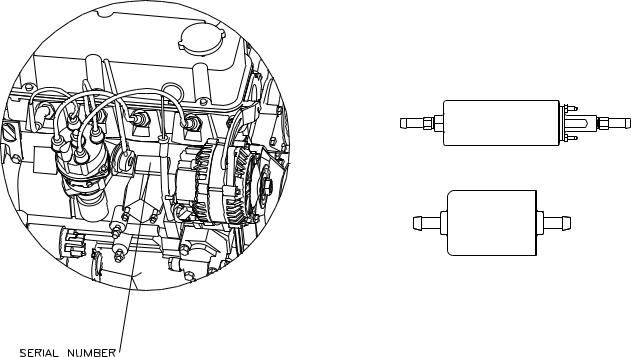
DATE STAMP LOCATION
When referring to an engine for assistance from your dealer, ProChem, or ZPP please identify your engine by the serial # and date code stamped on the
machined surface next to the oil dipstick.
FUEL PUMP AND FILTER
Your Everest EFI console was shipped to the dealer with a specific fuel pump and fuel filter. Ensure that ONLY these items are used in the installation of your unit. The EFI system is much more sensitive to unwanted material in the fuel stream. Contamination of the fuel stream may clog the injectors and adversely affect performance. Please be sure to adhere to the filter maintenance schedule located in the Operations Section of this manual.
# 790860
FUEL PUMP
# 790858
FUEL FILTER
3-4 |
EVEREST EFI 980197 06/30/04 |
OPERATIONS
ERROR CODES
On rare occasions the engine may experience abnormal operation conditions and shut down. Upon shutdown the amber light in the upper right corner of the instrument panel will repeatedly flash an error code to help you determine the root cause of the shutdown. Double-digit numbers are flashed one digit at a time, (i.e. “12” would be shown as “Flash”, pause, “Flash”, “Flash”). The codes are listed below for your convenience.
|
|
|
|
TROUBLE |
TROUBLE |
CODE/FLAG |
|
CONDITION |
SEQUENCE |
RESULT |
RETAINED IN |
||
|
CODE |
FLAG |
MEMORY WITH |
|||
|
|
|
|
|||
|
|
|
|
|
|
KEY OFF? |
1 |
ENGINE OIL PRESSURE SWITCH |
|
OIL PRESSURE SWITCH INDICATES OIL PRESSURE |
|
2 |
NO |
INDICATES LOW OIL PRESSURE |
|
IS LOW FOR 1 COMPLETE SECOND - ENGINE |
|
|||
|
|
|
|
|
||
2 |
ENGINE OVERHEATING |
1 |
RPM LIMITED TO 950 MAXIMUM FOR 60 SECONDS |
|
3 |
NO |
|
ONCE 60 SECOND TIME LIMIT IS EXCEEDED - |
|
|
|
||
DETECTED (COOLANT >= 239 F) |
2 |
|
3 |
NO |
||
|
ENGINE SHUTDOWN OCCURS |
|
||||
|
|
|
|
|
|
|
|
TRANSMISSION OIL |
1 |
RPM LIMITED TO 950 MAXIMUM FOR 60 SECONDS |
|
4 |
NO |
3 |
TEMPERATURE SWITCH |
2 |
ONCE 60 SECOND TIME LIMIT IS EXCEEDED - |
|
4 |
NO |
|
INDICATES OVERTEMP |
ENGINE SHUTDOWN OCCURS |
|
|||
|
|
|
|
|
||
4 |
BEGINNING OF DIAGNOSTIC |
|
NO FAULT CONDITION EXITS - SIGNIFIES |
12 |
|
YES-ALWAYS |
ROUTINE |
|
BEGINNING OF FLASH CODES |
|
PRESENT |
||
|
|
|
|
|||
|
|
1 |
TROUBLE CODE IS STORED IN MEMORY |
14 |
3 |
CODE RETAINED |
|
ENGINE COOLANT SENSOR |
IN MEMORY |
||||
|
|
|
|
|
||
|
|
|
|
|
|
|
|
INDICATES SHORT CIRCUIT OR |
|
|
|
|
FLAG CLEARS |
5 |
EXTREME OVERHEATING OF |
2 |
RPM LIMITED TO 950 MAXIMUM FOR 60 SECONDS |
14 |
3 |
WHEN IGNITION |
|
ENGINE (COOLANT TEMP >= 266 |
|
|
|
|
IS OFF |
|
F) |
|
ONCE 60 SECOND TIME LIMIT IS EXCEEDED - |
|
|
FLAG CLEARS |
|
|
3 |
14 |
3 |
WHEN IGNITION |
|
|
|
ENGINE SHUTDOWN OCCURS |
||||
|
|
|
|
|
IS OFF |
|
|
|
|
|
|
|
|
6 |
ENGINE COOLANT SENSOR |
|
TROUBLE CODE IS STORED IN MEMORY |
15 |
|
CODE RETAINED |
INDICATES OPEN CIRCUIT |
|
|
IN MEMORY |
|||
|
|
|
|
|
||
7 |
PEDAL POSITION SENSOR OVER |
|
TROUBLE CODE IS STORED IN MEMORY |
21 |
|
CODE RETAINED |
VOLTAGE (OVER 4.5 VOLTS) |
|
|
IN MEMORY |
|||
|
|
|
|
|
||
8 |
PEDAL POSITION SENSOR |
|
TROUBLE CODE IS STORED IN MEMORY |
22 |
|
CODE RETAINED |
UNDER VOLTAGE (0 VOLTS) |
|
|
IN MEMORY |
|||
|
|
|
|
|
||
9 |
AIR TEMPERATURE SENSOR |
|
TROUBLE CODE IS STORED IN MEMORY |
23 |
|
CODE RETAINED |
INDICATES OPEN CIRCUIT |
|
|
IN MEMORY |
|||
|
|
|
|
|
||
10 |
AIR TEMPERATURE SENSOR |
|
TROUBLE CODE IS STORED IN MEMORY |
24 |
|
CODE RETAINED |
INDICATES SHORT CIRCUIT |
|
|
IN MEMORY |
|||
11 |
MAP SENSOR CIRCUIT |
|
TROUBLE CODE IS STORED IN MEMORY |
33 |
|
CODE RETAINED |
INDICATES HIGH VLOTAGE (4.98 |
|
|
IN MEMORY |
|||
12 |
MAP SENSOR CIRCUIT |
|
TROUBLE CODE IS STORED IN MEMORY |
34 |
|
CODE RETAINED |
INDICATES SHORT TO GROUND |
|
|
IN MEMORY |
|||
13 |
OXYGEN SENSOR - LEAN |
|
TROUBLE CODE IS STORED IN MEMORY |
44 |
|
CODE RETAINED |
CONDITION DETECTED |
|
|
IN MEMORY |
|||
14 |
OXYGEN SENSOR - RICH |
|
TROUBLE CODE IS STORED IN MEMORY |
45 |
|
CODE RETAINED |
CONDITION DETECTED |
|
|
IN MEMORY |
EVEREST EFI 980197 06/30/04 |
3-5 |
OPERATIONS
ZENITH DISTRIBUTOR LOCATIONS
• |
ITAL ENGINE COMPANY (09046) |
OH, IN.KY,WV |
|
97 CYPRESS ST. SW |
PA (WESTERN) |
|
REYNOLDSBURG, OHIO 43068 |
PHONE:740/964-0089 |
•
•
CULLUM & BROWN, INC. (09045) |
KS, MO |
1607 WABASH |
PHONE:316/262-5156 |
WICHITA, KS 67214 |
800/362-3222 |
DIESEL ELECTRIC SERVICE & SUPPLY (09116) |
UT |
652 W. 1700 SOUTH |
PHONE:801/972-1836 |
SALT LAKE CITY, UT 84104 |
|
•
•
POWER EQUIPMENT COMPANY (09117) |
NE, IA |
15225 INDUSTRIAL RD. |
PHONE:402/330-5100 |
OMAHA, NE 68144 |
|
ENGINE WORKS, INC. (09178) |
IL |
1345 PARAMOUNT PKWY. |
PHONE:630/879-7977 |
BATAVIA, IL 60510 |
800-832-7217 |
•
•
•
FRONTIER EQUIPMENT, LTD. (09185) |
BC, AB |
8029 RIVER WAY |
PHONE:604/946-5531 |
DELTA, BC CANADA V4G IL3 |
|
GULF ENGINE & EQUIPMENT (09229) |
LA,MS |
2306 ENGINEERS RD. |
PHONE:504/393-1701 |
BELLE CHASSE, LA 70037 |
|
HAMILTON ENGINE SALES, INC. (09287) |
WA, OR, AK |
5540 N. E. COLUMBIA BLVD. |
PHONE:503/288-6714 |
PORTLAND, OR 97218 |
800/437-3644 |
•
•
H. G. MAKELIM COMPANY (09480) |
CA |
219 SHAW RD. |
PHONE:650/873-4757 |
SOUTH SAN FRANCISCO, CA 94080 |
|
LOFTIN EQUIPMENT COMPANY, INC. (09490) |
AZ |
12TH NORTH 45TH AVE. |
PHONE:602/272-9466 |
PHOENIX, AZ 85043 |
|
•
•
M.G. BRYAN EQUIPMENT COMPANY (09503) |
TX,OK |
4834 READING ST. |
PHONE:214/631-9787 |
DALLAS, TX 75247 |
|
NORPRO ISUZU ENGINES, INC. (09505) |
CT, MA, VT, NH, ME, RI |
385 TOWN ST. |
PHONE:860/873-0100 |
HADDAM, CT 06423 |
|
•
•
SOUTHEAST SERVICE & SUPPLY (09698) |
GA |
1721-E OAKBROOK DR. |
PHONE:770/448-4251 |
NORCROSS, GA 30093 |
800/241-4595 |
TOTAL POWER LTD |
ON |
6670 EXCEISIOR COURT |
PHONE:905/670-1535 |
MISSISSAUGA, ON CANADA L5T 2J2 |
|
3-6 |
EVEREST EFI 980197 06/30/04 |
CHEMICAL REQUIREMENTS
This cleaning unit, due to its chemical injection pump design, can be used with a variety of water-diluted chemical compounds (either acidic or alkaline), depending on the job to be done. However, to obtain optimum results with this unit, we recommend using the PROCHEM line of chemicals. For information on using the cleaning compounds, refer to the PROCHEM chemical manual.
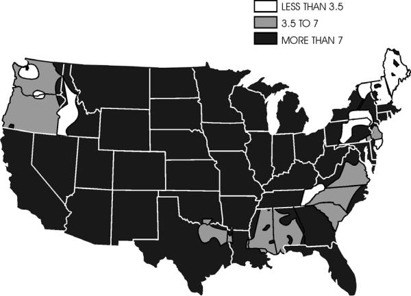
WATER REQUIREMENTS
Hard water deposits will adversely affect the plumbing and heat exchange systems on this unit. The map below will give you an idea of where areas of high water hardness may occur. However, any water supply obtained from a well is almost always hard water and a water softener will be needed to protect your equipment.
NOTE: Equipment malfunction or component failure caused by hard water scaling is NOT covered under the warranty.
HARD WATER MAP
OPERATION & SYSTEMS
If you are operating this unit in an area where the unit will be using water in which the hardness exceeds
3-1/2 grains, we highly recommend a suitable water softener be installed. If using a water softener, it must have a five (5) GPM (or greater) flow capacity without any hose constrictions.
Using a water softener will reduce maintenance and decrease down time caused by hard water scaling. It will also allow cleaning chemicals to be more effective in lower concentrations.
If you require a water softener, PROCHEM has a model to meet your needs. Please contact your nearest distributor for information, price, and availability.
EVEREST EFI 980197 06/30/04 |
3-7 |
OPERATION & SYSTEMS
29
28
27
26
25
24
23
22
21
1 |
30 |
2 |
3
4
5
6
8
7
9
10
LOW PRESSURE
SOLUTION SOLUTION REGULATOR
PRESSURE
HIGH PRESSURE 1000-3000 PSI
|
|
WARM |
SOLUTION TEMPERATURE |
HOT |
|
|
|
CONTROL VALVE |
|
|
|
CONDENSED OPERATING INSTRUCTIONS |
|
|
|
|
STARTING |
|
|
|
|
1. CONNECT WATER HOSES TO WATER INLET CONNECTIONS AND TURN ON WATER SUPPLY. |
|
|
|
LOW PRESSURE |
2. CONNECT CLEANING AND VACUUM HOSES TO THE DESIRED CLEANING TOOL AND CONSOLE. |
|
|
|
4. PUSH IN ENGINE CHOKE AFTER ENGINE HAS STARTED. |
|
|
|
|
SOLUTION SCREEN |
3. PULL OUT ENGINE CHOKE,TURN SOLUTION PUMP TO OVERRIDE AND TURN IGNITION KEY TO START. |
|
|
|
6. INSERT CHEMICAL INLET AND PRIME TUBING INTO CHEMICAL CONTAINER. |
|
||
|
|
5. SET THROTTLE AT LOW POSITION. |
|
|
|
|
7. TURN CHEMICAL PRIME VALVE TO PRIME AND ALLOW CHEMICAL TO CIRCULATE. AFTER ALL AIR BUBBLES HAVE BEEN REMOVED FROM THE CHEMICAL |
||
|
|
TUBING, TURN THE VALVE TO THE OFF POSITION, OPEN THE CHEMICAL FLOW AND FLOW SIMULATOR VALVES. SET THE DESIRED CHEMICAL FLOW RATE WHILE |
||
|
|
OBSERVING THE FLOW METER INDICATOR. FLOW SIMULATOR VALVE MUST BE IN THE OPEN POSITION TO SET CHEMICAL FLOW. WHEN DESIRED FLOW IS |
||
|
|
REACHED, TURN FLOW SIMULATOR VALVE OFF. |
|
|
HIGH PRESSURE |
HIGH PRESSURE |
8. FOR QUICK HEAT-UP, REFER TO OPERATING INSTRUCTIONS. |
|
|
SHUTDOWN AND DAILY MAINTENANCE |
|
|
||
SOLUTION REGULATOR |
|
|
||
SOLUTION OUTLET |
1. CLOSE CHEMICAL METERING VALVE. |
|
|
|
|
2. ALLOW THE UNIT TO RUN FOR 2 MINUTES WITH THE VACUUM HOSE DISCONNECTED TO REMOVE MOISTURE AND SPRAY WD40 (OR EQUIVALENT) INTO |
|||
|
|
THE VACUUM LUBRICATION CUP. THIS WILL PREVENT CORROSION DUE TO MOISTURE. |
|
|
|
|
3. SET ENGINE THROTTLE AT IDLE POSITION AND OPEN FLOW SIMULATOR VALVE, ALLOWING THE WATER TEMPERATURE TO COOL DOWN. |
||
|
|
4. TURN OFF IGNITION SWITCH. |
|
|
|
|
5. DISCONNECT ALL HOSES AND TOOLS. |
|
|
|
|
6. DRAIN WASTE TANK INTO AN APPROVED SOURCE. |
|
|
LOW PRESSURE
SOLUTION OUTLETS
CARPET AND
UPHOLSTERY
LOW PRESSURE SOLUTION
50-1000 PSI
20 |
19 |
18 |
31 |
17 |
16 |
15 |
11
12
13
14
3-8 |
EVEREST EFI 980197 04/17/06 |
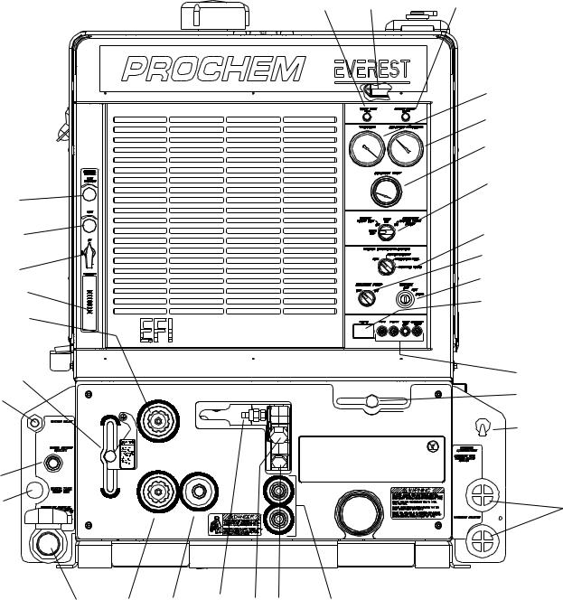
1. WASTE TANK FULL INDICATOR LIGHT
This indicator light is activated when the waste tank is full. When lit the unit will shutdown protecting the equipment from damage. This also indicates that the waste tank must be emptied before the unit can be brought back in service.
NOTE: Never dispose of waste water in storm drains, water ways or on ground areas. Always dispose of waste in accordance with local state and federal laws.
2.SERVICE ENGINE SOON
This light, when flashing, signals a problem with the unit. When this occurs, troubleshooting is required.
3.VACUUM GAUGE
This gauge indicates in inches of mercury how much vacuum the system is producing at any given time.
4.SOLUTION PRESSURE GAUGE
This gauge registers the amount of pressure in the system.
5.SOLUTION TEMPERATURE GAUGE
This gauge measures the temperature of the cleaning solution as it exits the machine.
6.WASTE PUMPOUT AND AUXILIARY WATER PUMP SWITCH
This four-position switch is for activating the waste pumpout device. It also serves to activate the fresh water transfer pump. For turning on pumps, rotate clockwise. For turning off pumps, rotate counter clockwise.
7.SOLUTION PUMP SWITCH
This switch serves to energize the magnetic clutch to turn the water pump on or off. Turn clockwise for activating the pump and counter clockwise for deactivating the pump.
COMPONENTS
8.ENGINE SPEED CONTROL
This serves to set the engine speed and operating parameters. The ‘Low’, ‘Medium’ and ‘High’ settings are set for upholstery cleaning, single wand cleaning, and dual wand cleaning respectively.
9.KEY SWITCH
The key switch controls the power for the machine. To turn the machine on, rotate the key clockwise until the starter engages the engine. When machine is running let off the switch and engine will continue to run. To turn power off, rotate key counter clockwise to stop position, engine will then stop.
10. HOUR METER
The hour meter records the number of hours the unit has run. This serves as a time recorder for servicing the machine.
11. CIRCUIT BREAKERS
These serve to protect the circuits from electrical spike and over loads and protects wires from damage and fire.
12.SOLUTION TEMPERATURE CONTROL VALVE
This valve enables additional heat exchangers to contribute more heat to the system if necessary. By moving the lever to the right it adds more heat, by moving to the left it removes heat.
13.OIL CUP
The oil cup allows lubricant spray to reach the vacuum blower.
EVEREST EFI 980197 06/30/04 |
3-9 |

COMPONENTS
14.VACUUM INLETS
The vacuum inlets serve as connecting point for vacuum hoses.
15.SOLUTION OUTLETS
The solution outlets are the connecting point for the high pressure cleaning hoses. These outlets are quick disconnects that allow hoses to be plugged into the unit.
16. SOLUTION SCREEN
The solution screen is located on the front of the machine. The function of this screen is to trap foreign particles from exiting the machine and plugging the orifices of the cleaning tools. This screen is part of the machine maintenance cleaning.
17. CHEMICAL CHECK VALVE
The chemical check valve allows chemicals to enter the system and travel in a singular direction to the wand. The chemical check valve prevents chemicals from traveling upstream into the solution system of the unit.
18.HIGH PRESSURE SOLUTION OUTLET
The high pressure solution outlet is the connecting point for the high pressure hose. This outlet is a quick disconnect that allows pressure washing hoses to be plugged into the unit. (HP unit only)
19.HIGH PRESSURE REGULATOR
The regulating valve controls the amount of pressure in the pressure washing circuit.
By turning the handle clockwise, It has the effect of increasing the pressure. Turning it clockwise has the effect of lowering the pressure. (HP unit only)
20.WASTE OUTLET
This valve allows the waste tank to be emptied. Turning clockwise opens the valve.
NOTE: This valve must be closed during operation.
21.WASTE PUMPOUT
This auxiliary pump serves to empty the waste collection tank automatically. A float located inside the tank automatically turns off and on when the solution level reaches certain points.
22. WARM WATER OUTLET
The warm water outlet allows the cleaning technician to drain hot water from the water box for mixing chemical.
Water from this valve is hot.
23. WATER INLET
This quick connect allows the water supply hose to be connected to the unit.
24. PRESSURE SELECTOR VALVE
This selector valve allows the technician to switch from high pressure to low pressure. By moving the handle to the up position, the high pressure circuit is activated allowing the unit to be used as a pressure washer. By positioning the valve handle to the down position, the low pressure circuit is activated allowing the unit to be used for carpet cleaning. (HP unit only)
25.LOW PRESSURE REGULATOR
This pressure regulating valve allows the low pressure circuit to be adjusted by turning the handle clockwise the pressure will increase, by turning counter clockwise the pressure will decrease.
3-10 |
EVEREST EFI 980197 06/30/04 |
26. FLOW METER
The flow meter is a gauge to indicate how much liquid chemical is being introduced in the water system. The quantity can be increased by turning the chemical flow knob counter clockwise.
27. CHEMICAL PRIME CONTROL VALVE
This valve allows the chemical to circulate through the chemical system with little or no restriction. It also purges out air that may be trapped in the lines and cavities of the chemical pump. By turning the valve clockwise the injection system is enabled.
28. CHEMICAL METERING VALVE
The chemical metering valve regulates the amount of chemical that is injected into the system. Clockwise rotation of the knob closes the valve. Counter clockwise rotation opens the valve, allowing more chemical to enter the system.
OPERATIONS & SYSTEMS
29. FLOW SIMULATOR VALVE
This valve allows solution to move through the machine and chemical to be injected simulating the cleaning process. This allows the operator to set the chemical flow level without connecting tools to the machine. It is also useful in troubleshooting. The valve is turned off by rotating the knob clockwise and opened by turning the knob counter clockwise.
30. PANEL LIGHT
This light is useful if the machine is used in a poorly lit area or night use. It is helpful in reading the instruments and gauges.
31. TEMPERATURE BALANCE ORIFICE
The temperature balance orifice helps to balance and stabilize the solution temperature within the system.
EVEREST EFI 980197 06/30/04 |
3-11 |
OPERATION & SYSTEMS
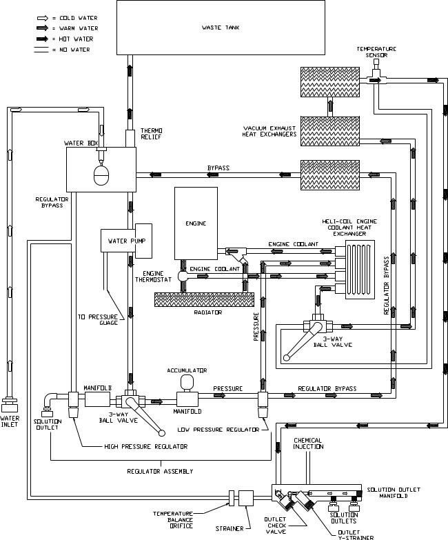
WATER PUMPING AND HEAT
TRANSFER SYSTEM
Cold water enters the console through the water inlet. When the water box is full the valve will automatically shut off.
Water then flows from the water box, through a strainer, into the water pump where it is pumped to the pressure regulator manifold where the pressure regulator provides and maintains the desired pressure setting.
The pressure regulator manifold includes a nitrogen charged accumulator which helps reduce pressure spikes from the pump.
A certain amount of water is by-passed from the pressure regulator due to over pumping capacity of the water pump. Water that is not called for in the cleaning process is channeled through a heat exchanger box into the first heater core from the front of the unit. This bypass water may circulate several times through the bypass heat exchanger allowing the water to be pre-warmed.
The next stage of heating and water flow is to the helicoil, when water is called for in the cleaning process it flows to the helicoil under pressure. Heat from the engine coolant is exchanged to the cleaning solution through a series of spiraled copper tubing. This allows the engine coolant to travel in a counter rotating direction to the cleaning water during the exchange process creating a very efficient transfer of heat out of the engine and into the cleaning solution.
The third stage of plumbing and heat exchange takes place in the 2nd heater core located in the heater box. These hot engine/vacuum exhaust gases are forced through heater core #2 creating the third stage of heat transfer to the cleaning solution.
Finally, the hot solution passes to the outlet manifold where cleaning chemicals are injected from the chemical pulse pump. This manifold serves as a temperature sensing point and a connecting point for the high-pressure hoses. Also a check valve is located in this outlet manifold prohibiting chemicals from backing up into the system.
The cleaning solution then passes through highpressure hoses and is distributed by the cleaning tool to a surface that is being cleaned, completing the water pumping and heating cycle of the cleaning unit.
3-12 |
EVEREST EFI 980197 06/30/04 |

OPERATIONS
SINGLE SYSTEM WATER FLOW DIAGRAM LOW PRESSURE (WARM)
EVEREST EFI 980197 06/30/04 |
3-13 |
OPERATIONS
SINGLE SYSTEM WATER FLOW DIAGRAM LOW PRESSURE (HOT)
3-14 |
EVEREST EFI 980197 06/30/04 |

CHEMICAL INJECTION SYSTEM
The chemical injection system is unique in that it utilizes the pressure spikes generated by the highpressure water pump to move chemical into the main pressure stream. The high pressure spikes move the diaphragm in the chemical pulse pump forcing small amounts of liquid chemical to be moved in a single direction of flow with the aid of two check valves.
The chemical is picked up from the container and fed through the flow meter to the chemical pulse pump where it is pressurized.
OPERATIONS
After reaching the chemical pulse pump the chemicals can either go into a bypass loop to purge air from the system or the chemical can be directed by the chemical selector valve to the metering valve. The metering valve creates an orifice allowing the correct amount of chemical to enter the outlet manifold. The outlet manifold assembly is complete with a check valve that will not allow the chemicals to travel upstream into the plumbing system of the unit.
The chemicals are then mixed with hot pressurized water that make up a solution for the cleaning application.
EVEREST EFI 980197 06/30/04 |
3-15 |

OPERATIONS
VACUUM SYSTEM
The engine turning an air pump generates vacuum. The air is channeled in one side of the vacuum pump, compressed and discharged on the opposite side, creating airflow.
The movement of air is used to do the work necessary for the extraction process. A vacuum nozzle applied to the carpet surface removes moisture, dirt and spent chemicals. These elements are conveyed back to a separating tank utilizing hoses and the force of air. Particles of moisture and dirt are separated in the vacuum tank using a series of changes in direction and velocity. The air is then filtered and rushes into the vacuum pump.
The vacuum pump compresses and heats the incoming air. The hot discharged air is forced down stream into a silencer for noise abatement. After exiting the silencer, this hot air is mixed with hot gases from the engine. This mixture of hot gases are then forced through 3 radiators serving as heat collectors. Heat from the engine and vacuum pump is then transferred into the plumbing system raising the water temperature for better cleaning.
|
VACUUM |
HEATER COIL #1 |
INLET |
|
HEATER COIL #2
VACUUM
GAUGE
HEATER COIL #3 |
LUBRICATION |
|
CUP |
VACUUM
SILENCER  PUMP
PUMP
 VACUUM
RELIEF
VALVE
LEVEL SENSOR
WASTE |
TANK |
FILTER |
3-16 |
EVEREST EFI 980197 06/30/04 |

PRE-RUN INSPECTION
NOTE: Operation of this unit is simple. However, only trained personnel should proceed.
Operate this unit and equipment only in a wellventilated area. Exhaust fumes contain carbon monoxide which is an odorless and deadly poison that can cause severe injury or fatality. DO NOT operate this unit where the exhaust may enter any building doorway, window, vent, or opening of any type. Do not operate this unit while the exhaust discharge is directed at plants or animals.
CHECK FOR ADEQUATE FUEL
Check the fuel tank to be certain there is adequate fuel to complete the job. This unit uses approximately .95 to 1.18 gallons of fuel per hour, depending on the speed setting.
REMOVE TOOLS FROM VEHICLE
Remove any tools or hoses from the van which you will require.
WATER SUPPLY CONNECTION
NOTE: Before connecting your water hose to the supply faucet, flush out the faucet until the water is free of any debris. Flush out any debris which may be in your water inlet hose.
1.Connect the water supply hose to the water inlet quick-connect at the left front of the console. Connect the hose to the water supply faucet.
NOTE: Never use your waste pump outlet hose as a water inlet hose. Use only clean hoses for water inlet.
2.Turn the water supply faucet on. The water will fill the water box.
OPERATIONS
PRESSURE HOSE
Before starting the unit, connect the pressure hose(s) to the outlet connection(s) at the front of the unit. Connect the cleaning tool(s) to the pressure hose(s).


 DANGER
WATER UNDER HIGH PRESSURE AT HIGH TEMPERATURE CAN CAUSE BURNS, SEVERE PERSONAL INJURY, OR COULD BE FATAL. SHUT DOWN MACHINE, ALLOW TO COOL DOWN, AND RELIEVE SYSTEM OF ALL PRESSURE BEFORE REMOVING VALVES, CAPS, PLUGS, FITTINGS, FILTERS AND BOLTS.
ROTATING |
|
DANGER |
|
||
MACHINERY. |
|
|
WATER UNDER |
|
|
PRESSURE AT HIGH |
|
DO NOT MODIFY |
TEMPERATURE. |
|
|
IMPROPER |
|
UNIT WITHOUT |
MODIFICATION OF |
|
WRITTEN |
EQUIPTMENT CAN |
|
PERMISSION |
CAUSE SEVERE |
|
FROM |
PERSONAL INJURY |
|
|
OR COULD BE |
|
MANUFACTURER |
FATAL. |
|
|
VACUUM HOSE
Connect the vacuum hose(s) to the vacuum inlet connection(s) at the front of the unit. Connect the other end of the vacuum hose(s) to the cleaning tool(s).
EVEREST EFI 980197 06/30/04 |
3-17 |

OPERATIONS
PRIMING THE CHEMICAL PUMP
1.Connect water hose to water inlet connection and turn on water supply.
2.Connect cleaning and vacuum hoses to the desired cleaning tool and console.
3.Insert chemical inlet and prime tubing into chemical container.
4.Turn ignition key to start.
5.Set throttle to low speed.
6.Fill chemical container and inspect chemical filter.
7.Turn chemical prime valve to prime and allow chemical to circulate. After all air bubbles have been removed from chemical tubing, turn the valve to the horizontal (off) position and open the chemical metering valve, and the simulation valve. Set the desired chemical flow rate while observing the flow meter indicator. Simulator valve must be in the open position to set chemical flow. When desired flow is reached turn simulator valve off.
8.Set throttle to maximum position with vacuum ports blocked off for quick unit heat up.
WASTE PUMP (OPTIONAL)
1.If your unit is equipped with an automatic waste pump, connect one end of a garden hose to the pump-out connection on the console and the other end to an appropriate waste disposal.
2.Turn the pump-out switch on the control panel to the ON position. Turn the toggle switch on the pump unit to “ON”. The waste pump will operate automatically throughout the cleaning operation.
We recommend that you use a 3/4" I.D. water hose as a waste pump outlet hose. DO NOT use a hose smaller than 5/8" I.D.
NEVER use your automatic waste pump outlet hose as a water inlet hose.
NEVER dispose of waste in storm drains, water ways, or on ground areas. Always dispose of waste in accordance with Local, State, and Federal laws.
Your unit should be in the correct throttle position for your cleaning operation or extracting. A float switch located inside the waste tank will automatically shut down the unit when it reaches its full capacity.
When this occurs, empty the waste tank before continuing.
CLEANING
Observe the following guidelines, while cleaning:
1.Before proceeding make sure the nozzles are functioning properly.
a.To check , hold the wand about one foot above the surface to be cleaned and open the wand valve. A full spray should be observed from the cleaning nozzles.
b.If the nozzles are not showing a full spray pattern, adjust nozzles for proper pattern, clean, or replace nozzles, if required.
2.Normally chemical is applied on the push stroke of the wand when cleaning and vacuuming is done on the pull stroke. For heavily soiled carpets the wand may be used in a scrubbing manner, apply chemical in both push and pull strokes. Always finish up an area with a vacuum stroke.
3.When cleaning, keep the working opening (mouth) flat on the surface being cleaned. Keep the wand moving when the valve is open.
4.The unit will automatically shut-down when the waste tank is full. This will prevent water being drawn into the vacuum pump. If shut-down occurs, empty the waste tank before proceeding.
3-18 |
EVEREST EFI 980197 06/30/04 |

HIGH PRESSURE SHUTDOWN & RETURN TO LOW PRESSURE SYSTEM
1.Turn off water pump and release pressure.
2.Bleed off excessive pressure build-up by operating pressure washer gun for 5 seconds.
3.Move solution selector control valve from “High Pressure” operations to “Low Pressure” operation.
4.Squeeze pressure washer gun trigger again to remove any residual pressure
5.Disconnect high pressure gun and hose from high pressure disconnect.
6.Open ball valve, located between the chemical pump and water pump.
7.Operate under normal low pressure instruction or follow normal shutdown procedures.
Pro-Chem recommends the use of the ProChem chemical injector (P/N 61-951538) for use in combination with any chemical/detergent additives.
Pro-Chem also recommends the use of ProChem high-pressure spray wands. Pro-Chem offers a dual barrel wand (P/N 60-950505). Contact your Pro-Chem dealer for recommendations in your particular application.
The operation of the high-pressure system also requires a high-pressure hose capable of handling the increased pressure loads of the high-pressure system. NEVER use your lowpressure system hoses with the high-pressure system. Pro-Chem offers a special high pressure hose, P/N 10-805513, rated for pressure washer activities. Only use Pro-Chem approved hoses and fittings. Ensure that your hoses and fittings are rated for your operational pressures.
OPERATION & SYSTEMS
DE-FLOODING OPERATIONS
De-flooding operations involve removal of water from carpet and flooring. This differs from normal cleaning operations in that no water or solution is required. An automatic waste pump-out is highly recommended for all de-flooding operations due to the large amount of water removal often required.
1.Move the temperature control lever from the “hot” position to the “warm” position.
2.Ensure that the solution pump is in off position.
FREEZING PROTECTION
If the unit is exposed to freezing weather the water in the unit may freeze, causing SERIOUS DAMAGE to the unit. To avoid this, the following is recommended during the cold weather season.
When the unit is not in use, always park it in a heated building.
While in operation, avoid long shutdowns as the unit provides heat while running. Shut it down just prior to leaving for the next job.
If a heated building is not available, we recommend that you winterize the unit with anti-freeze. At present, it is only possible to winterize units, which do not have an auxiliary water tank. Units with auxiliary water tanks must be stored in a heated building when not in use.
EVEREST 980197 11/25/06 |
3-19 |

OPERATION & SYSTEMS
UPHOLSTERY CLEANING
Upholstery tool, part #78513
1.Set engine speed control to “Low/Upholstery” setting to minimize excess heat.
2.Use one (1) “80015” spray tip in tool.
SHUTDOWN AND DAILY MAINTENANCE (LOW PRESSURE)
1.Close chemical metering valve.
2.Allow the unit to run for 2 minutes with the vacuum hose disconnected to remove moisture. Spray WD40 (or equivalent) into the vacuum lubrication cup. This will prevent corrosion due to moisture.
3.Set engine speed control to idle position and allow the water temperature to cool down, unitizing the simulator valve in the open position to bleed off residual hot water left in the system.
4.Turn off ignition switch.
5.Disconnect all hoses and tools.
6.Drain waste tank.
HIGH PRESSURE (3000 PSI) SYSTEM OPERATION (OPTIONAL)
The high-pressure water system can produce water pressures in excess of 3000psi. Water at these pressures will cause severe injury. DO NOT direct any discharges at persons. If contact with a person does occur and penetration of the skin does seem possible, contact medical personnel immediately. This machine is to be used by trained cleaning professionals only. Ensure all operators are trained in the operation of this equipment. Keep cleaning area clear of all persons and objects.
Ensure that proper Personal Protective Equipment (PPE) is used during the operation of this equipment. Failure to use proper PPE could result in injury. Ensure required ventilation and/or breathing apparatuses are used with a chemical injection system. Check with your chemical vendor for proper safety requirements.
OPERATION
The “HP” units are equipped with a water pump and water delivery system that can support pressurewashing operations up to 4.5 gallons per minute at 3000 PSI. This system is normally used for highpressure washing and hard surface cleaning.
1.Move the temperature selection valve from the “hot” position to the “warm” position.
2.Allow water temperature to cool to below 160 deg F.
3.Close ball valve located between the chemical pump and the water pump.
Failure to close this valve will result in severe damage to the chemical pump diaphragms.
1.Connect hose and either pressure washer gun or hard surface cleaning tool to high pressure disconnect.
2.Move the pressure selection valve from the “low pressure” position to the “high pressure” position.
3.Adjust high-pressure regulator to desired operational pressure.
3-20 |
EVEREST 980197 11/25/06 |
WINTERIZING YOUR UNIT
1.Shut off the water supply. Disconnect the water inlet hose from the front of your console.
2.Connect all pressure hoses and tools that may have water in them.
3.Start the unit and turn water pump on. Open the tool valve until water pressure drops and water stops flowing.
4.Fill the water box with approximately two gallons of 100% glycol base anti-freeze.
5.Start the unit.
6.Open the tool valve until anti-freeze begins to come out of the tool. Recover ALL anti-freeze that comes out of the tools into an approved container. We strongly recommend that you recycle and re-use the anti-freeze.
Repeat this procedure with all the remaining tools. After all tools and pressure hoses have been filled with anti-freeze, disconnect and store them.
7.Turn the solution pump switch OFF. Attach the winterizing loop hose with attachment, Part #10-805380, to the bottom solution outlet connection and the water inlet connection. Turn the solution pump switch ON.
Allow the unit to run for approximately 3 minutes with the winterizing loop hose attached.
OPERATIONS
8.Prime the chemical system with 50/50 antifreeze/water mix. Insert the chemical inlet and prime discharge tubes into the anti-freeze container. Turn the chemical valve to PRIME until anti-freeze begins to flow out of the prime hose.
9.Now turn the chemical valve and flow simulator valves to the open position, making certain that the flow meter indicates flow and that all antifreeze drains out of the chemical hose into an approved container, after 30 seconds, turn off both valves.
HIGH PRESSURE
Turn solution pressure valve to high pressure and key the high pressure wand until anti-freeze begins to come out of the wand. Recover all anti-freeze into an approved container. We strongly recommend that you recycle and re-use the anti-freeze.
After completing these procedures, shut the unit down. The unit is now winterized.
EVEREST EFI 980197 06/30/04 |
3-21 |
 Loading...