


BLAZER GT
MOBILE CLEANING UNIT
Operating Instructions (ENG)
MODELS: BLAZER GT
1.001-121.0
Read instructions before operating the machine.
86317260 - BC 08/30/13
Left intentionally blank

Machine Data Log / Overview
Model:
Date of Purchase:
Serial Number:
Dealer:
Address:
Phone Number:
Sales Representative:
Welcome…and congratulations on the purchase of your Mobile Cleaning Unit. This instruction manual is a guide for operating and servicing your unit. Read this manual completely before installing or operating this unit.
This unit offers you personal convenience. All of your instrumentation and controls have been positioned to give you easy access for operation and daily maintenance.
Proper operation and service are essential to the efficient functioning of this unit. When maintained correctly, this unit will have a long, trouble-free life.
The service methods described in this manual are explained in such a manner that servicing may be performed accurately and safely. Proper service varies with the choice of procedure, the skill of the mechanic, and the tools or parts available. Before attempting any repair, make certain that you are thoroughly familiar with this equipment and are equipped with the proper tools. Any questions pertaining to operating or servicing this unit should be directed to your nearest dealer.
THIS UNIT MUST BE INSTALLED BY THE DEALER FROM WHOM YOU PURCHASED IT IN ACCORDANCE WITH THE PRESCRIBED INSTALLATION PROCEDURES.
Information in this document is subject to change without notice and does not represent a commitment on the part of PROCHEM.
Warranty Registration
Thank you for purchasing a Prochem product. Warranty registration is quick and easy.
Your registration will allow us to serve you better over the lifetime of the product.
To register your product go to : www.prochem.com/WarrantyRegistration.aspx
For customer assistance: 1-800-776-2436
86317260 BLAZER GT |
1 |

Table of Contents
Machine Data Log / Overview . . . . . . . . . . . . . . . . . 1 Table of Contents . . . . . . . . . . . . . . . . . . . . . . . . . . . 2
Receiving Your Unit . . . . . . . . . . . . . . . . . . . . . . . . . 4
Acceptance of Shipment . . . . . . . . . . . . . . . . . . . . . 4 Equipment List . . . . . . . . . . . . . . . . . . . . . . . . . . . . . 4
How to Use This Manual . . . . . . . . . . . . . . . . . . . . . 5
Safety
IMPORTANT SAFETY INSTRUCTIONS. . . . . . . . . 6
Hazard Intensity Level . . . . . . . . . . . . . . . . . . . . . . . 8
Safety Labels . . . . . . . . . . . . . . . . . . . . . . . . . . . . . . 9
Installation
Dealer Responsibility . . . . . . . . . . . . . . . . . . . . . . . 10 Vehicle Requirements . . . . . . . . . . . . . . . . . . . . . . 10 Lifting Unit Onto Vehicle . . . . . . . . . . . . . . . . . . . . 10 Positioning Unit In Vehicle . . . . . . . . . . . . . . . . . . . 10 Bolting Down Unit And Waste Tank. . . . . . . . . . . . 11 Electrical Wiring . . . . . . . . . . . . . . . . . . . . . . . . . . . 11 Layout with 60 Gallon Waste Tank . . . . . . . . . . . . 12 Layout with 60 Gallon Waste Tank & Optional
Auxiliary Water Tank . . . . . . . . . . . . . . . . . . . . . 13 Layout with 100 Gallon Waste Tank . . . . . . . . . . . 14 Layout with 100 Gallon Waste Tank & Optional
Auxiliary Water Tank . . . . . . . . . . . . . . . . . . . . . 15 Waste Tank To Console Connection . . . . . . . . . . . 16 Fuel Pump Assembly Installation. . . . . . . . . . . . . . 16 Van Bulkhead Installation . . . . . . . . . . . . . . . . . . . 17 Fuel Supply & Return Line Installation. . . . . . . . . . 18 Battery Connection . . . . . . . . . . . . . . . . . . . . . . . . 19 Initial Operational Settings . . . . . . . . . . . . . . . . . . . 20
Operations
Technical Specifications . . . . . . . . . . . . . . . . . . . . 21
Fuel Requirements. . . . . . . . . . . . . . . . . . . . . . . . . 22
Engine Oil Requirements . . . . . . . . . . . . . . . . . . . . 22
Altitude Requirements . . . . . . . . . . . . . . . . . . . . . . 22
Chemical Requirements. . . . . . . . . . . . . . . . . . . . . 22
Water Requirements . . . . . . . . . . . . . . . . . . . . . . . 23
Components. . . . . . . . . . . . . . . . . . . . . . . . . . . . . . 24
Vacuum System. . . . . . . . . . . . . . . . . . . . . . . . . . . 27
Water Pumping and Heat Transfer System . . . . . . 28
Heat Exchanger . . . . . . . . . . . . . . . . . . . . . . . . . . . 28
Chemical Injection System. . . . . . . . . . . . . . . . . . . 30
Pre-Run Inspection / Setup . . . . . . . . . . . . . . . . . . 31
Check For Adequate Fuel . . . . . . . . . . . . . . . . . . . 31
Remove Tools From Vehicle . . . . . . . . . . . . . . . . . 31
Water Supply Connection . . . . . . . . . . . . . . . . . . . 31
High Pressure Solution Hose. . . . . . . . . . . . . . . . . 31
Vacuum Hose . . . . . . . . . . . . . . . . . . . . . . . . . . . . 31
Filters . . . . . . . . . . . . . . . . . . . . . . . . . . . . . . . . . . . 31
Priming the Chemical Pump . . . . . . . . . . . . . . . . . 32
Waste Pump (Optional) . . . . . . . . . . . . . . . . . . . . . 32
Cleaning. . . . . . . . . . . . . . . . . . . . . . . . . . . . . . . . . 32
Upholstery Cleaning. . . . . . . . . . . . . . . . . . . . . . . . 33
Shutdown and Daily Maintenance . . . . . . . . . . . . . 33
Freezing Protection . . . . . . . . . . . . . . . . . . . . . . . . 33
Overheating Protection . . . . . . . . . . . . . . . . . . . . . 33
Winterizing the Unit . . . . . . . . . . . . . . . . . . . . . . . . 34
Removing Anti-Freeze From the Unit . . . . . . . . . . 35
2 |
86317260 BLAZER GT |

Maintenance
Service Schedule . . . . . . . . . . . . . . . . . . . . . . . . . .36
Key Checkpoints . . . . . . . . . . . . . . . . . . . . . . . . . . .38
External Fuel Pump Maintenance. . . . . . . . . . . . . .38
Chemical Supply System Maintenance . . . . . . . . .38
Heat Exchanger System Maintenance . . . . . . . . . .38
Vacuum Pump Maintenance. . . . . . . . . . . . . . . . . .39
Engine. . . . . . . . . . . . . . . . . . . . . . . . . . . . . . . . . . .39
Vacuum Pump . . . . . . . . . . . . . . . . . . . . . . . . . . . .40
Solution Pump. . . . . . . . . . . . . . . . . . . . . . . . . . . . .41
Vacuum Inlet Filter (in Waste Tank) . . . . . . . . . . . .41
Vacuum Relief Valve. . . . . . . . . . . . . . . . . . . . . . . .41
Vacuum Pump Drive Belts . . . . . . . . . . . . . . . . . . .41
Solution Pump Drive Belts . . . . . . . . . . . . . . . . . . .42
Float Valve (Water Box) . . . . . . . . . . . . . . . . . . . . .42
Waste Tank Float Valve . . . . . . . . . . . . . . . . . . . . .42
Waste Tank Strainer Basket . . . . . . . . . . . . . . . . . .42
Waste Tank Vacuum Inlet Filter . . . . . . . . . . . . . . .42
Check Valve (Outlet). . . . . . . . . . . . . . . . . . . . . . . .43
Chemical Pump. . . . . . . . . . . . . . . . . . . . . . . . . . . .43
Chemical and Temperature Control Valves . . . . . .43
Pressure Regulator . . . . . . . . . . . . . . . . . . . . . . . . .43
Vacuum Hoses . . . . . . . . . . . . . . . . . . . . . . . . . . . .43
High Pressure Solution Hoses . . . . . . . . . . . . . . . .43
Optional Waste Pump-Out . . . . . . . . . . . . . . . . . . .43
General Service Adjustments. . . . . . . . . . . . . . . . .44
Engine Speed . . . . . . . . . . . . . . . . . . . . . . . . . . . . .44
Check Valve (Solution Outlet). . . . . . . . . . . . . . . . .44
Water Box . . . . . . . . . . . . . . . . . . . . . . . . . . . . . . . .44
Chemical Pump. . . . . . . . . . . . . . . . . . . . . . . . . . . .44
Solution and Vacuum Pump Drive Belts . . . . . . . . .44
Packing Nut Adjustments For Chemical Valves . . .45
Pressure Regulator . . . . . . . . . . . . . . . . . . . . . . . . .45
Troubleshooting . . . . . . . . . . . . . . . . . . . . . . . . . . .46
Table of Contents
Parts
Frame . . . . . . . . . . . . . . . . . . . . . . . . . . . . . . . . . . 52
Side Panel. . . . . . . . . . . . . . . . . . . . . . . . . . . . . . . 54
Control Panel . . . . . . . . . . . . . . . . . . . . . . . . . . . . 56
Engine. . . . . . . . . . . . . . . . . . . . . . . . . . . . . . . . . . 60
Vacuum Pump . . . . . . . . . . . . . . . . . . . . . . . . . . . 62
Solution Pump. . . . . . . . . . . . . . . . . . . . . . . . . . . . 64
Heat Exchanger . . . . . . . . . . . . . . . . . . . . . . . . . . 68
Pressure Regulator & Temperature Control Valve 70
Solution Outlet . . . . . . . . . . . . . . . . . . . . . . . . . . . 72
Water Box . . . . . . . . . . . . . . . . . . . . . . . . . . . . . . . 74
60 Gallon Waste Tank . . . . . . . . . . . . . . . . . . . . . 76
100 Gallon Waste Tank . . . . . . . . . . . . . . . . . . . . 78
Battery Floor Mount . . . . . . . . . . . . . . . . . . . . . . . 80
Chemical Jug Floor Mount . . . . . . . . . . . . . . . . . . 82
Fuel Pump. . . . . . . . . . . . . . . . . . . . . . . . . . . . . . . 84
Hose Diagram . . . . . . . . . . . . . . . . . . . . . . . . . . . . 86
Wiring Diagram . . . . . . . . . . . . . . . . . . . . . . . . . . . 87
Options
Hose Accessories . . . . . . . . . . . . . . . . . . . . . . . . . 90 Exhaust - Optional . . . . . . . . . . . . . . . . . . . . . . . . 92 Automatic Pumpout - Dual Diaphragm - Optional. 94 Wand - Titanium Six Jet - Optional . . . . . . . . . . . . 96 Wand - Ergo Titanium Six Jet - Optional. . . . . . . . 98 Wand - Quad Jet - Optional . . . . . . . . . . . . . . . . 100 Wand - Tri Jet -Optional . . . . . . . . . . . . . . . . . . . 102 Stair Tool - Optional . . . . . . . . . . . . . . . . . . . . . . 104 Upholstery Tool - Optional . . . . . . . . . . . . . . . . . 106 Shelf Assembly - Optional. . . . . . . . . . . . . . . . . . 108 Auxiliary Water Tank with Pump-Optional . . . . . 110 Water Tank Dual with Demand Pump - Optional 112 Water Tank - Demand Pump - Optional . . . . . . . 114 Auxiliary Water Tank - Optional . . . . . . . . . . . . . 116 Hose Reel - Optional. . . . . . . . . . . . . . . . . . . . . . 118 Motorized Hose Reel - Tank - Optional. . . . . . . . 120 Motorized Hose Reel - Optional . . . . . . . . . . . . . 122 E Z - Charge Water Softener - Tank & Tray -
Optional . . . . . . . . . . . . . . . . . . . . . . . . . . . . 124 E Z - Charge Water Softener - Filter - Optional . 126 E Z - Charge Water Softener - Brine System - . . . .
Optional . . . . . . . . . . . . . . . . . . . . . . . . . . . . 128
86317260 BLAZER GT |
3 |

Receiving Your Unit
Acceptance of Shipment
Every part of your cleaning unit was carefully checked, tested, and inspected before it left our manufacturing plant. Upon receiving the unit, make the following acceptance check:
1.The unit should not show any outward signs of damage. If damaged, notify the common carrier immediately.
2.Check your equipment and packing list. The standard cleaning unit should arrive equipped with the following items (unless otherwise specified) and any optional accessories which were ordered:
Equipment List
1.Console.
2.Waste tank.
3.Fuel pump assembly.
4.100 ft. of 2” vacuum hose.
5.1 vacuum hose connector.
6.100 ft. of 1/4” high pressure hose with quick connects.
7.50 ft. water supply hose with quick connect.
8.Installation bolting kit.
9.Installation mounting plates.
10.Operation and service manuals for engine, water pump, and vacuum pump.
11.Carpet wand.
12.5 gallon jug and holder.
13.Hose clamps for fuel & vacuum hoses.
4 |
86317260 BLAZER GT |
This manual contains the following sections:
•How to Use This Manual
•Safety
•Installation
•Operations
•Maintenance & Service
•Parts List
The HOW TO USE THIS MANUAL section will tell you how to find important information for ordering correct repair parts.
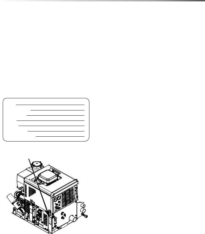
Parts may be ordered from authorized dealers. When placing an order for parts, the machine model and machine serial number are important. Refer to the MACHINE DATA box which is filled out during the installation of your machine. The MACHINE DATA box is located on the inside of the front cover of this manual.
Model:
Date of Purchase:
Serial Number:
Dealer:
Address:
Phone Number:
Sales Representative:
The model and serial number of your machine is located approximately where shown
The SAFETY section contains important information regarding hazardous or unsafe practices for this machine. Levels of hazards are identified that could result in product damage, personal injury, or severe injury resulting in death.
How to Use This Manual
The INSTALLATION section contains information on how to properly install the unit in your vehicle.
The OPERATIONS section is to familiarize the operator with the operation and function of the machine.
The MAINTENANCE section contains preventive maintenance to keep the machine and its components in good working condition. They are listed in this general order:
•Engine
•Vacuum Pump
•Solution Pump
•Drive Belts, Pulleys & Hubs
•Chemical Pump
•Hoses
•Exhaust Heat Exchanger
•General Service Adjustments
•Machine Troubleshooting
The PARTS LIST section contains assembled parts illustrations and corresponding parts list. The parts lists include a number of columns of information:
•REF – column refers to the reference number on the parts illustration.
•PART NO. – column lists the part number for the part.
•PRV NO. – reference number.
•QTY – column lists the quantity of the part used in that area of the machine.
•DESCRIPTION – column is a brief description of the part.
•SERIAL NO. FROM – If this column has an (*) and a Reference number, see the SERIAL NUMBERS page in the back of your manual. If column has two asterisk (**), call manufacturer for serial number. The serial number indicates the first machine the part number is applicable to. The main illustration shows the most current design of the machine. When a boxed illustration is shown, it displays the older design.
•NOTES – column for information not noted by the other columns.
NOTE: If a service or option kit is installed on your machine, be sure to keep the KIT INSTRUCTIONS which came with the kit. It contains replacement parts numbers needed for ordering future parts.
NOTE: The manual part number is located on the lower left corner of the front cover.
86317260 BLAZER GT |
5 |

Safety
IMPORTANT SAFETY INSTRUCTIONS
When using this machine, basic precaution must always be followed, including the following:
READ ALL INSTRUCTIONS BEFORE USING THIS MACHINE.
These symbols mean WARNING or CAUTION. Failure to follow warnings and cautions could result in fatality, personal injury to yourself and/or others, or property damage. Follow these instructions carefully!
Read the operator's manual before installing or starting this unit. Failure to adhere to instructions could result in severe personal injury or could be fatal.
Operate this unit and equipment only in a well-ventilated area. Exhaust fumes contain carbon monoxide which is an odorless and deadly poison that can cause severe injury or fatality. DO NOT run this unit in an enclosed area. DO NOT operate this unit where the exhaust may enter any building doorway, window, vent, or opening of any type.
Gasoline is extremely flammable and its vapors can explode if ignited. Store gasoline only in approved containers, in well-ventilated, unoccupied buildings away from sparks or flames. Never carry any gasoline or flammable material in the vehicle. Fumes may accumulate inside the vehicle and ignite, causing an explosion.
DO NOT store any type of flammable material in the vehicle.
This unit must be operated with the vehicle or trailer doors open in order to ensure adequate engine ventilation.
DO NOT operate engine if gasoline is spilled. Avoid creating any ignition until the gasoline has been cleaned up. Never use gasoline as a cleaning agent.
DO NOT place hands, feet, hair, or clothing near rotating or moving parts. Avoid any contact with moving parts! Rotating machinery can cause injury or fatality.
Never operate this unit without belt guards. The high speed moving parts, such as belts and pulleys, should be avoided while this unit is running. Severe injury, damage, or fatality may result.
DO NOT service this unit while it is running. The high-speed mechanical parts as well as high temperature components may result in severe injury or severed limbs.
Never touch electrical wires or components while the engine is running. They can be sources of electrical shock.
Engine components can get extremely hot from operation. To prevent severe burns, DO NOT touch these areas while the engine is running or immediately after the engine is turned off.
DO NOT touch any part of the exhaust system while this unit is running. Severe burns may result. Before servicing this unit, allow it to cool down. This will prevent burns from occurring.
Water under high pressure at high temperature can cause burns, severe personal injury, or fatality. Shut down machine, allow to cool down, and relieve system of all pressure before removing valves, caps, plugs, fittings, filters, and bolts.
Always wear hearing protection when unit is running. Always comply with your company’s Personal Protection Equipment (PPE) plan. Always comply with local noise ordinance when operating units.
6 |
86317260 BLAZER GT |

Safety
DO NOT leave the vehicle engine running while operating this unit.
Dangerous Acid, Explosive Gases! Batteries contain sulfuric acid. To prevent acid burns, avoid contact with skin, eyes and clothing. Batteries produce explosive hydrogen gas while being charged. To prevent a fire or explosion, charge batteries only in well ventilated areas. Keep sparks, open flames, and other sources of ignition away from the battery at all times. Keep batteries out of the reach of children. Remove all jewelry when servicing batteries.
Before disconnecting the negative (-) ground cable, make sure all switches are OFF. If ON, a spark will occur at the ground cable terminal which could cause an explosion if hydrogen gas or gasoline vapors are present. When disconnecting the battery, ALWAYS disconnect the negative (-) terminal FIRST.
DO NOT smoke around the unit. Gas fumes may accumulate and be ignited. The battery is also extremely flammable. This will prevent possible explosions.
DO NOT damage the vehicle in any manner during installation. When routing fuel lines DO NOT place the hose in any location where damage may occur to the hose or vehicle. Avoid any contact with moving parts, areas of high temperature, brake lines, fuel lines, muffler, catalytic converter, or sharp objects.
There is no fuel solenoid shut off on this unit. Use only the provided CARB approved fuel hose for fuel lines. When traversing the vehicle floor with fuel lines, always use a bulkhead adapter. This will prevent leakage and ensure that the hose is not punctured by vehicle vibration abrasion.
Use only ProChem supplied fuel installation kits. Ensure to use the kit specific for the truckmount model and van model being used. When traversing the vehicle floor with fuel lines, always use a bulkhead adapter. This will prevent leakage and ensure that the hose is not punctured by vehicle vibration abrasion.
DO NOT exceed your vehicle's weight limit. The console with empty 60 gallon waste tank and accessories weighs approximately 710 lbs (800 lbs. if mounted on water tank). Make certain to account for any additional accessories in your weight and balance calculations. Make certain that the vehicle has the correct axle rating. This will prevent unsafe vehicle driving conditions.
We require high-back seats on all vehicles in which units are to be installed for head and neck protection.
We recommend using a metal partition between the seats and equipment.
DO NOT operate this unit without the water supply attached and turned on. The solution pump and other vital components may be seriously damaged if this unit is permitted to operate dry without water.
Keep your vehicle work area clean. Wands, stair tools, and other accessories must be securely fastened before driving the vehicle.
All high pressure hoses must be rated for 3000 PSI at 250°F. Thermoplastic hoses do not meet these specifications and should not be used. Severe burns and injury may result if the hoses do not meet these requirements.
The winterizing loop hose assembly, Part # 86260700, PRV NO. 10-805380, is for winterizing use only. If used improperly, live steam may escape from this hose, causing it to whip around. Burns or injury may result.
Make certain that you receive complete training by the distributor from whom you purchased this unit. This unit uses high pressure and temperature. Improper or irresponsible use may result in serious injury.
Do not modify this unit in any manner. Improper modification can cause severe personal injury or fatality.
CALIFORNIA PROPOSITION 65 WARNING: Engine exhaust from this product contains chemicals known to the State of California to cause cancer, birth defects, or other reproductive harm.
86317260 BLAZER GT |
7 |

Safety
The following symbols are used throughout this guide as indicated in their descriptions:
Hazard Intensity Level
There are three levels of hazard intensity identified by signal words - WARNING and CAUTION and FOR SAFETY. The level of hazard intensity is determined by the following definitions:
WARNING - Hazards or unsafe practices which COULD result in severe personal injury or death.
CAUTION - Hazards or unsafe practices which could result in minor personal injury or product or property damage.
FOR SAFETY: To Identify actions which must be followed for safe operation of equipment.
Report machine damage or faulty operation immediately. Do not use the machine if it is not in proper operating condition. Following is information that signals some potentially dangerous conditions to the operator or the equipment. Read this information carefully. Know when these conditions can exist. Locate all safety devices on the machine. Please take the necessary steps to train the machine operating personnel.
FOR SAFETY:
DO NOT OPERATE MACHINE:
Unless Trained and Authorized.
Unless Operation Guide is Read and understood.
In Flammable or Explosive areas.
In areas with possible falling objects.
WHEN SERVICING MACHINE:
Avoid moving parts. Do not wear loose clothing; jackets, shirts, or sleeves when working on the machine. Use ProChem approved replacement parts.
8 |
86317260 BLAZER GT |
Safety
Safety Labels
The following WARNING LABELS are found on your cleaning unit. These labels point out important Warnings and Cautions which should be followed at all times. Failure to follow warnings and cautions could result in fatality, personal injury to yourself and/or others, or property damage. Follow these instructions carefully! DO NOT remove these labels.
NOTE: If at any time the labels become illegible, promptly replace them.
 CAUTION
Caution Label
P/N 86352580
Installation on vehicle fuel door.
|
LUBRICATE REGULATOR SEALS |
VACUUM |
EVERY 50 HOURS. |
RECOMMENDED LUBRICANT: |
|
LUBRICATION |
SYNCO SUPER LUBE |
|
SOLUTION PRESSURE |
|
|
|
REGULATOR |
LUBRICATE |
|
|
WITH VACUUM |
|
|
INLETS SEALED |
|
|
CHEMICAL |
SOLUTION TEMPERATURE |
|
CHECK |
||
VALVE |
|
CONTROL |
|
WARM |
HOT |
SOLUTION
SCREEN
SOLUTION OUTLET
CONDENSED OPERATING INSTRUCTIONS
STARTING |
SHUTDOWN AND DAILY MAINTENANCE |
||||
1. |
CONNECT WATER HOSE TO WATER INLET CONNECTION AND TURN ON WATER |
1. |
TURN CHEMICAL VALVE TO THE OFF POSITION, AND REMOVE THE |
||
|
SUPPLY. |
|
VACUUM HOSE. |
||
2. |
CONNECT SOLUTION AND VACUUM HOSE TO THE DESIRED CLEANING TOOL |
2. |
ALLOW THE UNIT TO RUN FOR 2 MINUTES WITH THE VACUUM HOSE |
||
|
AND TO THE CONSOLE. |
|
DISCONNECTED TO REMOVE MOISTURE THEN SPRAY A WATER |
||
|
|
|
DISPLACEMENT/LUBRICANT INTO THE VACUUM LUBRICATION CUP. |
||
3. PULL OUT THROTTLE 3/4 INCH. |
|
THIS WILL PREVENT CORROSION DUE TO MOISTURE. |
|||
4. |
PULL OUT ENGINE CHOKE. TURN WASTE PUMPOUT SWITCH TO OVERRIDE |
3. |
PUSH THE THROTTLE “IN” TO THE IDLE POSITION AND OPEN THE |
||
|
POSITION AND TURN IGNITION SWITCH TO START. |
|
TEMPERATURE BYPASS VALVE FOR 2 MINUTES ALLOWING THE UNIT |
||
5. |
PUSH IN CHOKE AND RELEASE OVERRIDE SWITCH AFTER ENGINE HAS |
|
TO COOL DOWN. |
||
|
|
|
|
||
|
STARTED. |
4. |
TURN OFF IGNITION SWITCH. |
||
6. |
INSERT CHEMICAL INLET AND PRIME HOSES INTO CHEMICAL CONTAINER. |
5. |
DISCONNECT ALL HOSES AND TOOLS. |
||
7. ROTATE CHEMICAL VALVE TO PRIME AND ALLOW CHEMICAL TO |
6. |
DRAIN WASTE TANK INTO AN APPROVED SOURCE AND CLEAN THE |
|||
|
FLOW THROUGH THE CHEMICAL CIRCUIT. AFTER ALL AIR BUBBLES |
|
STRAINER BASKET AND WASTE TANK FILTER. |
||
|
HAVE BEEN REMOVED, TURN THE CHEMICAL VALVE TO THE ON |
|
|
|
|
|
POSITION. |
|
|
|
|
8. |
TURN THE CHEMICAL VALVE TO RUN, OPEN THE VALVE ON THE CLEANING |
|
|
|
|
|
TOOL AND SET THE CHEMICAL FLOW VALVE TO THE DESIRED CHEMICAL |
|
|
|
|
|
FLOW RATE WHILE OBSERVING THE FLOW METER. |
|
|
|
|
9. |
SET THROTTLE TO THE DESIRED OPERATING SPEED. |
|
|
|
|
10. FOR QUICK HEAT-UP REFER TO THE OPERATING INSTRUCTION MANUAL.
Lower Front Panel Decal with warning labels
P/N 86316190
Warning Label
P/N 86186520
Caution Label
P/N 86186530
86317260 BLAZER GT |
9 |

Installation
Dealer Responsibility
Your distributor from whom you purchased this mobile cleaning unit is responsible for correct installation of this machine. The dealer is also responsible for initial training of your operators and maintenance personnel in proper operation and maintenance of this unit.
Vehicle Requirements
1.The unit should NOT be mounted in any motor vehicle of less than 1/2 ton capacityor 3/4 ton if equipped with one or more auxiliary fresh water tanks.
DO NOT exceed the vehicle’s axle weight limit. Include the console, full tanks, accessories, and operators in calculations.
2.If mounting in a trailer, make certain that trailer is rated for the total weight of UNIT AND TRAILER. Electric or hydraulic brakes should be provided, and a strict compliance with any State and Federal vehicle laws must be maintained.
3.The vehicle tires should have a load rating above the combined vehicle and unit weight.
4.We do not recommend using flooring materials that absorb water. This could result in rust and corrosion of the vehicle floor.
5.Padding under rubber floor mats should be removed before installing this unit.
6.We highly recommend using a drip tray under console (Part #86050370, or Part # 86050380 for units mounted on a water tank).
7.If using a trailer, console should be positioned so that it balances properly with respect to axle. Ten percent (10%) of the overall unit weight, should be on tongue.
Example: If loaded trailer weight is 2,000 lbs., tongue weight needs to be a minimum of 200 lbs. to tow properly.
Lifting Unit Onto Vehicle
Since console weighs approximately 500 lbs. pounds, we recommend using a forklift to lift unit onto vehicle. Position forks under unit from front and make CERTAIN that forks are spread to insert into frame slots.
Positioning Unit In Vehicle
Because vehicles vary in size and openings, individuals have their own preference as to where they want their units installed. We strongly recommend a side door installation for this and DO NOT recommend a rear door installation.
1.Enough space should be provided to assure adequate engine ventilation and room for service and maintenance.
2.The unit with waste tank and accessories must NOT exceed vehicle's axle weight limit. An empty 60 gallon waste tank and console weighs 710 lbs (800 lbs. if mounted on water tank).
3.DO NOT position the console closer than 12" from bottom of driver and passenger seats.
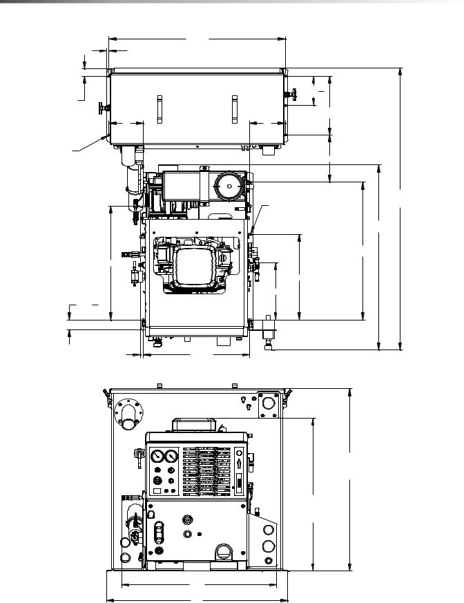
NOTE: For individuals who wish to make an engineering layout prior to positioning unit, refer to "Dimensional Data" illustrations for waste tank and console dimensions.
10 |
86317260 BLAZER GT |

Bolting Down Unit And Waste Tank
NOTE: When positioning waste tank with respect to console, hook up the vacuum hose to waste tank. This will ensure that waste tank is positioned correctly. Proceed once unit and waste tank are positioned in vehicle in desired location.
Before drilling any mounting holes in vehicle floor, make certain that when drilling, you will not do any damage to fuel tank, fuel lines, or any vital component which might affect operation or safety of vehicle.
1.Using console and waste tank mounting holes as a template, drill six 13/32" diameter holes for mounting console and six more 13/32" diameter holes for mounting waste tank.
2.Using installation hardware kit:
a.Insert six 3/8-16 x 2" hex head cap screws with flat washers through mounting holes in console, and six 3/8-16 x 2" hex head cap screws with flat washers through mounting holes in waste tank.
b.Install mounting plates underneath vehicle floor.
c.Screw 3/8-16 hex head locknuts on mounting screws and tighten them until console and waste tank are firmly secured to vehicle floor.
Installation
Electrical Wiring
Ensure all electrical wiring and battery cables are free from contact with any metal edge. Engine vibration could cause metal edge to cut wiring and possibly result in a fire. Be aware of where battery cables are run.
86317260 BLAZER GT |
11 |
Installation
Layout with 60 Gallon Waste Tank
|
|
|
3X 371 |
|
|
|
|
|
3X 21 |
8 |
|
|
|
|
|
|
|
|
|
|
|
|
|
|
2X 6 |
3 |
|
2X 121 |
|
|
|
16 |
|
|
|
|
|
2X 123 |
|
||
|
|
|
|
|
||
|
|
741 |
|
721 |
8 |
|
|
|
WASTE TANK |
|
|
||
|
|
|
|
|
|
|
6X Ø1332 |
|
|
|
|
10 |
|
|
|
|
|
|
|
|
|
|
|
|
|
|
5911 |
|
|
|
|
|
|
32 |
|
|
|
|
6X Ø7/16" X 5/8" SLOT |
LENGTH |
|
|
|
|
|
|
|
3831 |
|
|
|
|
|
|
32 |
|
|
|
|
|
2831 |
|
|
|
|
|
|
32 |
|
|
24 |
|
|
|
|
|
|
|
|
|
2X 18 |
|
|
|
|
|
|
2X 12 |
|
|
2X 2 |
3 |
|
|
|
|
|
32 |
|
CONSOLE |
|
|
|
|
|
|
|
|
|
|
|
|
3X |
11 |
3X 223 |
TOP VIEW |
|
|
|
|
16 |
8 |
|
||
|
|
|
|
|
||
|
|
|
|
|
3883 |
|
|
|
|
|
|
WASTE TANK |
|
|
|
|
|
|
HEIGHT |
|
|
|
|
|
321 |
|
|
|
|
|
|
8 |
|
|
|
|
|
|
CONSOLE |
|
|
|
|
|
|
HEIGHT |
|
|
|
|
|
323221 |
FRONT VIEW |
|
|
|
|
|
381 |
|
|
|
|
|
|
8 |
|
|
|
12 |
86317260 BLAZER GT |

Installation
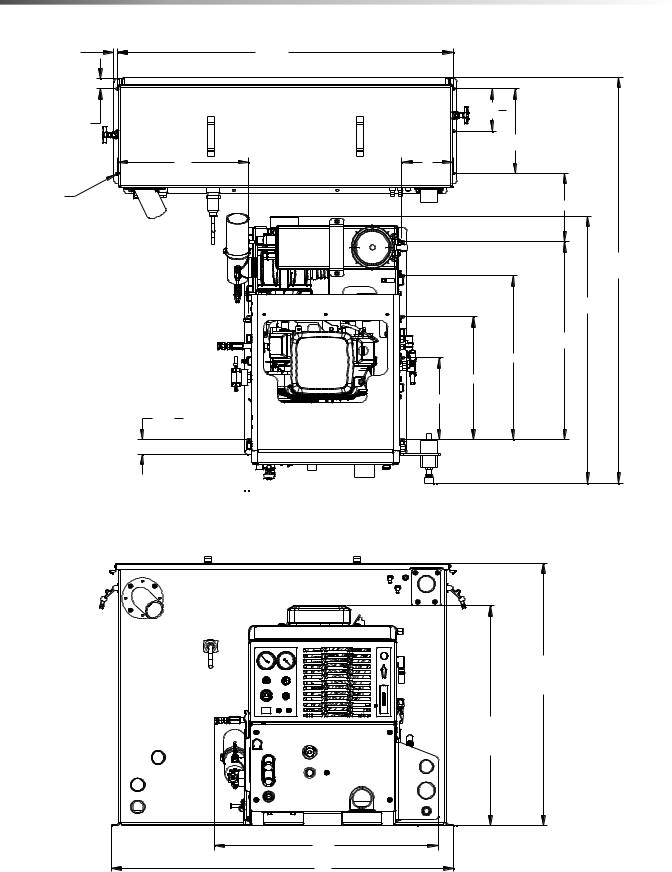
Layout with 60 Gallon Waste Tank & Optional Auxiliary Water Tank
|
|
381 |
|
|
|
|
|
2X 11 |
8 |
|
|
|
|
|
3X 371 |
3X |
|
|
|
|
|
2 |
1 |
|
|
||
|
|
8 |
|
2 |
|
|
2X 6 |
3 |
|
|
|
|
|
16 |
|
|
|
|
|
|
2X 123 |
|
|
|
|
|
|
8 |
415 |
|
21 |
|
|
|
|
32 |
WASTE TANK |
|
8 |
|
|
|
|
|
|
2X 15 |
|
|
|
|
|
|
|
721 |
|
|
|
|
|
|
8 |
|
6X Ø1332 |
|
|
|
|
32 |
|
AUXILIARY |
|
|
|
|
||
|
|
|
|
|
|
|
|
|
WATER TANK |
|
|
|
671613 |
|
|
|
2X 20 |
3 |
||
|
|
|
|
16 |
LENGTH |
|
|
|
|
|
|
2X 4013 |
|
|
|
|
|
|
|
32 |
|
|
CONSOLE |
|
|
|
|
|
6X 1332 |
|
|
|
|
|
|
TOP VIEW |
3X 3425 |
3X |
11 |
|
|
|
|
32 |
|
|
16 |
|
|
453 |
|
8 |
|
OVERALL |
383 |
HEIGHT |
|
|
8 |
|
WASTE TANK |
|
FRONT VIEW |
7 |
40 |
|
16 |
|
86317260 BLAZER GT |
13 |
Installation |
|
|
|
|
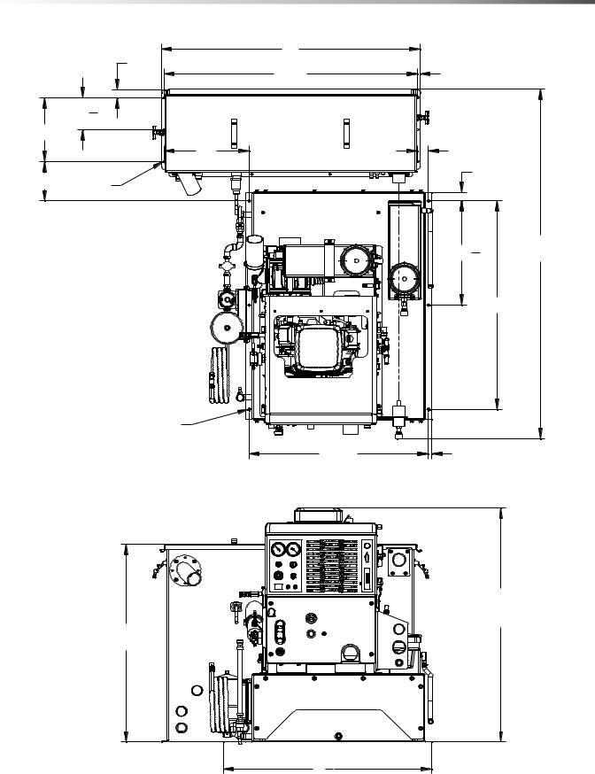
Layout with 100 Gallon Waste Tank |
|
|
||
3X |
1 |
3X 491 |
|
|
|
2 |
8 |
|
|
|
|
|
2X 6 |
3 |
2X 11 |
|
16 |
||
|
|
|
||
|
2 |
|
|
2X 1283 |
|
|
|
|
|
|
191 |
|
71 |
|
|
4 |
WASTE TANK |
2 |
|
|
|
|
|
|
6X Ø1332 |
|
|
|
10 |
|
|
|
|
|
|
|
|
9X Ø7/16" X 5/8" SLOT |
|
593211 LENGTH
383231
283231
2X 24
2X 18
2X 12
2X 2323
CONSOLE
3X 1611

 3X 2238

TOP VIEW
|
3883 |
|
WASTE TANK |
|
HEIGHT |
|
321 |
|
8 |
|
CONSOLE |
|
HEIGHT |
323221 |
FRONT VIEW |
5081 |
|
14 |
86317260 BLAZER GT |
Installation
Layout with 100 Gallon Waste Tank & Optional Auxiliary Water Tank
|
|
|
501 |
|
|
|
|
|
|
|
2X 11 |
8 |
|
|
|
|
|
|
|
3X 491 |
3X |
|
|
|
|
|
|
|
2 |
1 |
|
|
|
||
|
|
|
8 |
|
2 |
|
|
|
|
2X 6 |
3 |
|
|
|
|
|
|
|
16 |
|
|
|
|
|
|
|
2X 123 |
|
|
|
|
|
|
|
|
8 |
|
1615 |
|
21 |
|
|
|
|
|
|
|
|
|
|
|||
|
|
32 |
WASTE TANK |
|
8 |
|
|
|
|
|
|
|
|
|
2X 15 |
|
|
|
|
|
|
|
|
|
|
|
73221 |
6X Ø1332 |
|
|
|
|
8 |
|
|
|
|
|
AUXILIARY |
|
|
|
|
|
|
|
|
WATER TANK |
|
|
|
|
6713 |
|
|
|
|
2X 20 |
|
|||
|
|
|
|
3 |
16 |
|||
|
|
|
|
|
|
16 |
LENGTH |
|
|
|
|
|
|
|
|
2X 4013 |
|
|
|
|
|
|
|
|
32 |
|
|
|
|
CONSOLE |
|
|
|
|
|
|
|
6X 1332 |
|
|
|
|
|
|
|
|
TOP VIEW |
3X 3425 |
3X |
11 |
|
||
|
|
|
32 |
|
|
16 |
|
|
|
453 |
|
8 |
|
OVERALL |
383 |
HEIGHT |
|
|
8 |
|
WASTE TANK |
|
FRONT VIEW |
7 |
40 |
|
16 |
|
86317260 BLAZER GT |
15 |

Installation
Waste Tank To Console Connection
NOTE: Before connecting any hoses to the waste tanks, make certain the hose clamps are on each hose.
1.Connect the section of 2-7/8" I.D. internal vac hose between the 2-7/8" dia. vac outlet tube on the waste tank and the vacuum pump relief valve on the console. It may be necessary to cut this hose to fit. Tighten the hose clamps.
2.Connect the 2" I.D. waste removal hose to the 2" dia. tube at the bottom corner of the waste tank. Cut to desired length. Install brass ball valve on other end.
3.Connect 2-1/2" I.D. hose between waste tank vacuum inlet (upper right of waste tank) and vacuum inlet on lower side panel of console.
4.Connect the 3/16" blue hose from the water box to the lower flare fitting (angled downward) on the waste tank.
5.Run the 5/8" water box overflow hose through the van floor. Prior to drilling through the van floor, ensure that no damage will occur in drilling area. Ensure that you are in compliance with all local environmental laws.
6.Connect the console engine shut-off cord to the waste tank level sensor cord.
7.Connect the 3/16" blue hose from the solution temperature control valve to the other flare fitting (angled downward) on the waste tank.
Fire Extinguisher
We recommend that a fire extinguisher, preferably rated for A, B, & C type fires, be installed inside the vehicle.
Fuel Pump Assembly Installation
Before drilling the fuel line holes in the vehicle floor, make certain that when drilling you will not do any damage to the fuel tank(s), fuel lines, brake lines, heat shields, or any other vital component which might affect the operation or safety of the vehicle.
Do not mount this assembly, any hoses or components near the catalytic converter, exhaust, or any areas of high temperature. Avoid any contact with moving parts, areas of high temperature, brake lines, fuel lines, muffler, catalytic converter, or sharp objects.
1.Determine the position where the fuel pump assembly will be mounted. Check to ensure that the power cord length will support the mounting location. The pump should be mounted as low as possible and still be protected by the frame from road hazards. Mount the fuel pump with the discharge side of the pump higher than the suction side to eliminate the possibility of trapped air in the pump. Additional mounting holes are provided to allow for different mounting options.
2.Drill a 5/8" (.625) diameter hole in the vehicle floor for routing the fuel pump power cord to the truckmount console. Check to ensure that the cord length will support the location of the hole.
3.Route the power cord and install the hole grommet.
4.Do not connect the power cord to the truckmount console wiring harness until installation is complete.
16 |
86317260 BLAZER GT |
Installation
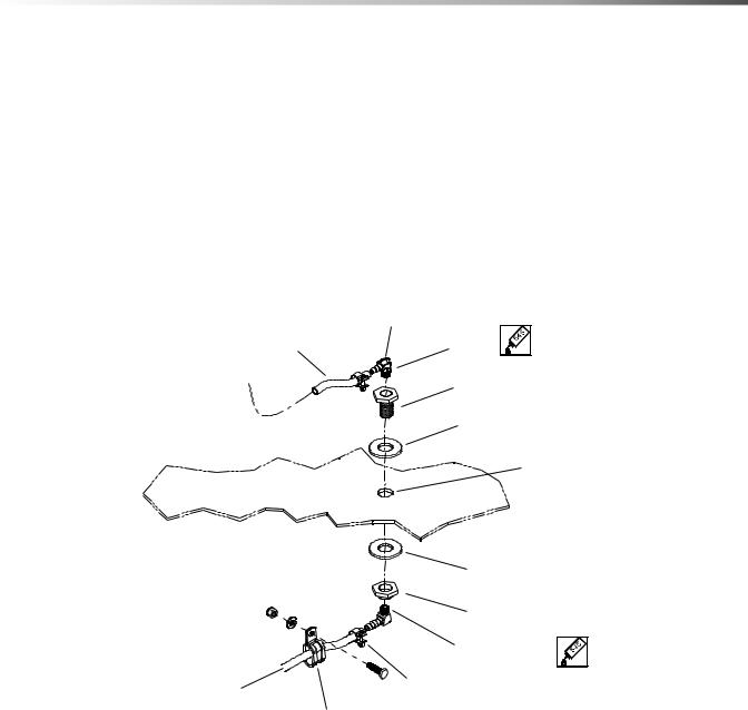
Van Bulkhead Installation
1.Select a location on the vehicle floor to drill the hole for the bulkhead adapter. This location should be situated in a position that eliminates the possibility of fuel line contact by either the operator(s) or accessories during the working hours or maintenance periods. Make certain that the supplied hoses will reach the location and work with the configuration you choose.
2.Drill a 5/8" (.625) diameter hole through the vehicle floor at the installation point chosen for the bulkhead.
3.Install the 1/8 NPT bulkhead adapter by inserting the adapter and tightening the nut on the opposite side of the van floor.
4.Attach the 1/8 NPT x 1/4 Hosebarb 90 degree elbow to the bulkhead inside the van to connect the fuel system to the console.
5.Attach the 1/4" fuel hose from the console to the 1/4” Hosebarb 90 degree elbow on the bulkhead.
|
HOSEBARB ELBOW |
FUEL HOSE |
LOCTITE |
TO CONSOLE |
BULKHEAD ADAPTER |
|
BULKHEAD GASKET |
|
5/8" DIA HOLE |
VEHICLE FLOOR |
|
FUEL HOSE FROM BYPASS FUEL FILTER
BULKHEAD GASKET
BULKHEAD NUT |
HOSEBARB ELBOW |
HOSE CLAMP
HOSE MOUNTING CLAMPS
USE AS NEEDED
86317260 BLAZER GT |
17 |
Installation
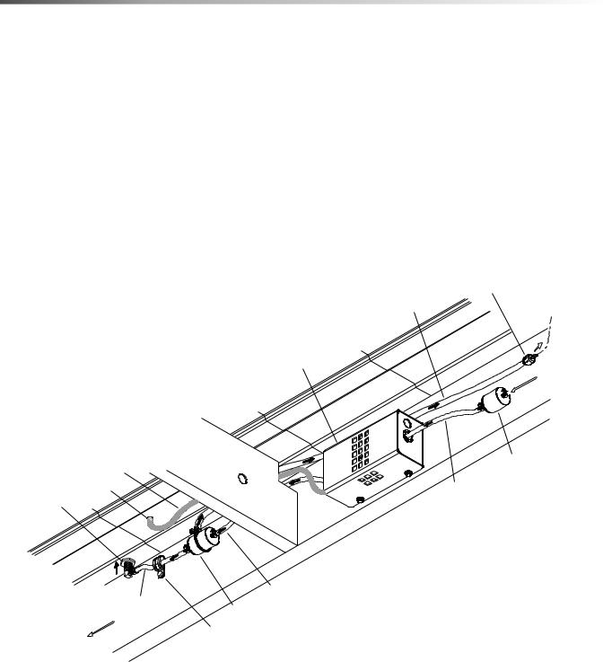
Fuel Supply & Return Line Installation
(Underneath Van)
1.Attach the 1/8 NPT x 5/16 Hosebarb 90 degree elbow to the bulkhead adapter underneath the van to be used for the fuel supply line.
2.Cut to length the 6' piece of 5/16" 50 PSI fuel hose used for the supply line from:
a.Bulkhead adapter to the outlet side of the bypass fuel filter.
b.Inlet side of the bypass fuel filter to the discharge side of the fuel pump.
c.Inlet side of the fuel pump to the outlet side of the inline fuel filter.
3.Cut to length the 6' piece of 1/4" fuel line to connect the bypass fuel filter with the fuel tank return using the appropriate fuel tap kit.
4.Check all hose clamps for tightness.
NOTE: Fuel tap kit installation instructions are found with appropriate fuel tap kit. Refer to Fuel Tap Kit Information Sheet (8.634-994.0)
|
CHECK VALVE |
|
1/4" RETURN HOSE |
RETURN TO VEHICLE |
|
FUEL SUPPLY |
||
|
ELECTRICAL FUEL
PUMP ASSEMBLY
FROM VEHICLE
FUEL SUPPLY
FUEL FLOW
FUEL FILTER
ELECTRICAL CORD |
|
BUSHING |
5/16" SUPPLY HOSE |
BULKHEAD CONNECTOR
5/16" SUPPLY HOSE
5/16" SUPPLY HOSE
BYPASS FUEL FILTER
FRONT OF VAN
HOSE MOUNTING CLAMP
USE AS NEEDED
18 |
86317260 BLAZER GT |
Installation
Battery Connection
Dangerous Acid, Explosive Gases! Batteries contain sulfuric acid. To prevent acid burns, avoid contact with skin, eyes, and clothing.
Batteries produce explosive hydrogen gas while being charged. To prevent a fire or explosion, charge batteries only in well-ventilated areas. Keep sparks, open flames, and other sources of ignition away from the battery at all times. Keep batteries out of the reach of children. Remove all jewelry when servicing batteries.
Before disconnecting the negative (-) ground cable, make sure all switches are OFF. If ON, a spark will occur at the ground cable terminal which could cause an explosion if hydrogen gas or gasoline vapors are present. When disconnecting the battery, ALWAYS disconnect the negative (-) terminal FIRST.
1.Attach the red positive (+) battery cable from the console starter solenoid to the positive (+) terminal on the battery and tighten the holding nut.
2.Next, attach the black negative (-) battery cable from the console ground to the negative (-) terminal on the battery and tighten the holding nut.
86317260 BLAZER GT |
19 |

Installation
Initial Operational Settings
NOTE: Due to temperature and altitude changes, the optimal settings for each truckmount must be adjusted after installation. Failure to make these adjustments may lead to poor unit performance and premature component failure.
Vacuum Pump
The maximum vacuum pressure obtainable at full throttle should be 13"Hg. If the unit is drawing a stronger vacuum (at full sealed suction) than 13" Hg, adjust the vacuum relief spring to 13" Hg.
Engine
Set RPM Values as shown below. Refer to Engine Operation Manual for adjustment instructions.
THROTTLE |
LOAD |
RPM* |
|
|
|
|
|
Idle |
None |
1400 rpm |
|
|
|
|
|
Full |
13" Hg. Vacuum |
3000 rpm |
|
500 psi pressure |
|||
|
|
||
|
|
|
|
Full |
None |
3200 rpm |
|
|
|
|
*±50 rpm tolerance
20 |
86317260 BLAZER GT |

Operations
Technical Specifications
ITEM |
DIMENSION/CAPACITY |
|
Engine speed |
3200 rpm |
|
1400 rpm (idle speed) |
||
|
||
Water pump rpm |
1655 rpm |
|
Vacuum pump rpm |
3200 rpm |
|
Water flow rate |
3.5 GPM (maximum) |
|
Water pump pressure |
1200 PSI (maximum) |
|
Vacuum relief valve |
13” Hg |
|
Waste tank capacity |
60 gallons / 100 gallons |
|
Console weight |
500 lbs. (590 lbs. If mounted on water tank) |
|
Console weight with: |
710 lbs. with empty waste tank |
|
60 gallon waste tank & accessories |
1152 lbs. with full waste tank |
|
Console weight with: |
800 lbs. with empty waste and water tanks |
|
1242 lbs. with full waste tank, and empty water tank |
||
60 gallon waste tank, water tank & accessories) |
||
1742 lbs. with full waste and water tanks |
||
|
||
Console weight with: |
720 lbs. with empty waste tank |
|
100 gallon waste tank & accessories |
1345 lbs. with full waste tank |
|
Console weight with: |
810 lbs. with empty waste tank |
|
1435 lbs. with full waste tank, and empty water tank |
||
100 gallon waste tank, water tank & accessories |
||
1935 lbs. with full waste and water tanks |
||
|
||
TORQUE |
VALUES |
|
Engine rear / vac pump pulley |
21 foot lbs |
|
Engine front / water pump pulley |
8 foot lbs |
86317260 BLAZER GT |
21 |

Operations
Fuel Requirements
Use unleaded gasoline ONLY. DO NOT use any gasoline additives. We recommend the use of clean, fresh, unleaded gasoline intended for automotive use. High octane gasoline should NOT be used with the engine on this unit. These engines are NOT designed to use E-85 or Flex Fuels.
Engine Oil Requirements
Use high quality detergent 10W-30 oil of at least API (American Petroleum Institute) service class SG, SH, SJ or higher.
NOTE: Using a lower service class oil or extending oil change intervals longer than recommended can cause engine damage.
NOTE: Synthetic oils meeting the listed classifications may be used with oil changes performed at recommended intervals. However to allow piston rings to properly seat, a new or rebuilt engine should be operated for at least 50 hours using standard petroleum based oil before switching to synthetic oil.
Altitude Requirements
Engines perform differently with increases/decreases in altitude. Be sure to check engine speeds during initial installation. See engine speeds in Technical Specifications section.
NOTE: To ensure correct engine operation at altitudes above 1525 meters (5000 ft.), it may be necessary to have an authorized dealer install a special high altitude jet kit in the carburetor. If a high altitude kit has been installed, the engine must be reconverted to the original jet size, before it is operated at lower altitudes, or overheating and engine damage can result.
Chemical Requirements
This cleaning unit, due to its chemical injection pump design, can be used with a variety of water-diluted chemical compounds (either acidic or alkaline), depending on the job to be done. However, to obtain optimum results with this unit, we recommend using the PROCHEM line of chemicals. For information on using the cleaning compounds, refer to the chemical manual.
22 |
86317260 BLAZER GT |

Water Requirements
Hard water deposits will adversely affect the plumbing and heat exchange systems on this unit. The map below will give you an idea of where areas of high water hardness may occur. However, any water supply obtained from a well is almost always hard water and a water softener will be needed to protect your equipment.
NOTE: Equipment malfunction or component failure caused by hard water scaling is NOT covered under the warranty.
Operations
If you are operating this unit in an area where the unit will be using water in which the harness exceeds 3-1/2 grains, we highly recommend a suitable water softener be installed. If using a water softener, it must have a five (5) GPM (or greater) flow capacity without any hose constrictions.
Using a water softener will reduce maintenance and decrease down time caused by hard water scaling. It will also allow cleaning chemicals to be more effective in lower concentrations
If you require a water softener, your dealer has a model to meet your needs. Please contact your nearest distributor for information, price, and abailability.
86317260 BLAZER GT |
23 |

Operations |
|
Components |
|
|
1 |
2 |
|
|
20 |
3 |
|
4 |
19 |
|
|
5 |
|
6 |
|
7 |
|
8 |
|
9 |
|
10 |
18 |
|
|
11 |
|
12 |
17 |
|
|
13 |
|
14 |
16 |
|
15 |
24 |
86317260 BLAZER GT |

Components
1.VACUUM GAUGE
This gauge indicates in inches of mercury how much vacuum the system is producing at any given time.
2.SOLUTION PRESSURE GAUGE
This gauge registers the amount of pressure in the system.
3.WASTE PUMPOUT / OVERRIDE SWITCH
This switch actuates the optional waste pumpout.
4.CHOKE
The choke is for restricting air to the carburetor, this enriches the fuel mixture. The primary purpose is for starting in cold temperatures. When the cable is pulled out air is restricted, when pushed in the engine is in run position.
Do NOT run engine with choke pulled out.
5.IGNITION SWITCH
The ignition switch controls the power for the machine. To turn the machine on, rotate the key clockwise while holding waste pump out switch to the override position until the engine starts. When machine is running let off the override switch and the engine will continue to run. To turn power off, rotate key counter clockwise to stop position, engine will then stop.
Operations
6.THROTTLE
The throttle cable is used to set the speed of the engine (rpm). The engine speed (rpm) may be increased by releasing the collar lock, pushing in the red button on the end of the handle, and pulling the handle straight out. Engine speed may be changed in smaller increments by rotating the throttle handle clockwise or counter-clockwise. The collar lock can be tightened to prevent the throttle from slipping and changing the engine speed.
7.HOUR METER
The hour meter records the number of hours the unit has run. This serves as a time recorder for servicing the machine.
8.CIRCUIT BREAKERS
These serve to protect the circuits from electrical spikes and over loads and protects wires from damage.
9.SOLUTION PRESSURE REGULATOR
The pressure regulator sets the pressure of the solution system. This spring loaded valve can be adjusted up or down. The pressure is increased by turning the valve clockwise, or reduced by turning the valve counter clockwise. (This valve must be maintained in accordance with this manuals maintenance table.)
10.LUBRICATION CUP
The lubrication cup allows lubricant spray to reach the vacuum blower.
86317260 BLAZER GT |
25 |

Operations
11.SOLUTION TEMPERATURE CONTROL VALVE
This valve allows the operator to control the solution temperature by bypassing hot water to the waste tank, for low temperature cleaning such as upholstery. Turning the valve counter clockwise opens the valve. Turning clockwise closes the valve and has the effect of stopping water from bypassing.
12.CHEMICAL CHECK VALVE
The chemical check valve allows chemicals to enter the system and travel in a singular direction to the wand. The chemical check valve prevents chemicals from traveling upstream into the solution system of the unit.
13.SOLUTION SCREEN
The solution screen is located on the front of the machine. The function of this screen is to trap foreign particles from exiting the machine and plugging the orifices of the cleaning tool.
14.SOLUTION OUTLET
The solution outlet is the connecting point for the high pressure solution hoses. This outlet is a quick disconnect that allows hoses to be plugged into the unit.
15.EXHAUST
Exhaust fumes contain carbon monoxide which is an odorless and deadly poison that can cause severe injury or fatality. DO NOT run this unit in an enclosed area. DO NOT operate this unit where the exhaust may enter any building doorway, window, vent, or opening of any type
16.WATER INLET
This quick connect allows the water supply hose to be connected to the unit.
17.VACUUM INLETS
The vacuum inlets serve as the connecting point for vacuum hoses.
18.FLOW METER
The flow meter is a gauge to indicate how much liquid chemical is being introduced in the water system. The quantity can be increased by turning the chemical flow knob counter clockwise.
19.CHEMICAL PRIME CONTROL VALVE
This valve allows the chemical to circulate through the chemical system with little or no restriction. It also purges out air that may be trapped in the lines and cavities of the chemical pump. By turning the valve clockwise the injection system is enabled.
20.CHEMICAL METERING VALVE
The chemical metering valve regulates the amount of chemical that is injected into the system. Clockwise rotation of the knob closes the valve. Counter clockwise rotation opens the valve, allowing more chemical to enter the system.
26 |
86317260 BLAZER GT |

Vacuum System
The engine turning the vacuum pump generates vacuum. The air is channeled in one side of the vacuum pump, compressed and discharged on the opposite side, creating airflow.
The movement of air is used to do the work necessary for the extraction process. A vacuum nozzle applied to the carpet surface removes moisture, dirt and spent chemicals. These elements are conveyed back to a separating tank utilizing hoses and the force of air. Particles of moisture and dirt are separated in the vacuum tank using a series of changes in direction and velocity. The air is then filtered and rushes into the vacuum pump.
HOT AIR TO
HEAT EXCHANGER
Operations
The vacuum pump compresses and heats the incoming air. The hot discharged air is forced down stream into a silencer for noise abatement. After exiting the silencer, this hot air is mixed with hot air exhaust gases from the engine. This mixture of hot air and gases are then forced through 2 radiators serving as heat collectors. Heat from the engine and vacuum pump is then transferred into the plumbing system raising the water temperature for better cleaning.
The vacuum pump speed is factory set to maximize vacuum pressure and provide sustained system life. Do not alter the vacuum speed outside the recommended range shown in the Technical Specifications section.
LUBRICATION
CUP
VACUUM |
|
RELIEF |
VACUUM |
VALVE |
GAUGE |
VACUUM |
|
|
INLET |
VACUUM |
|
|
|
|
|
SILENCER |
VACUUM |
|
|
|
|
|
PUMP |
|
LEVEL SENSOR |
|
|
(ENGINE SHUT-OFF SWITCH) |
|
|
|
|
|
|
|
|
|
|
|
|
|
|
|
|
FILTER |
|
|
|
|
|
|
|
|
|
|
|
|
|
|
|
|
|
|
|
|
|
|
|
|
|
|
|
|
|
|
|
|
|
|
|
|
|
|
|
|
|
|
|
|
|
|
|
|
|
|
|
|
|
|
|
|
|
|
|
|
|
|
|
|
|
|
|
|
|
|
|
|
|
|
|
|
|
|
|
|
|
|
|
|
|
|
|
|
|
|
|
|
|
|
|
|
|
|
STRAINER |
|
|
|
|
|
|
|
|
|
|
|
|||||||
|
|
|
|
|
|
|
|
|
|
|
||||||||
|
|
|
||||||||||||||||
|
|
|
||||||||||||||||
|
|
|
||||||||||||||||
|
|
|
|
|
|
|
|
|
|
|
|
|
|
|
|
|
|
|
|
|
|
|
|
|
|
WASTE TANK |
|||||||||||
86317260 BLAZER GT |
27 |

Operations
Always wear hearing protection and proper personal protection equipment when operating unit.
Water Pumping and Heat Transfer System
Cold water enters the console through the water inlet. When the water box is full the valve will automatically shut off.
Water then flows from the water box, through the strainer, into the solution pump. The water is pumped to the pressure regulator manifold, which provides and maintains the desired pressure setting.
The pressure regulator manifold includes a pulse hose, which helps reduce pressure spikes from the pump.
A certain amount of water is by-passed from the pressure regulator due to over pumping capacity of the solution pump. Water that is not called for in the cleaning process is channeled through a copper heater core in the front of the heat exchanger box. This bypass water circulates several times through the heater core pre-warming the water.
The gases coming from the vacuum pump and the engine exhaust are forced through the second heater core creating the hottest area of the heat exchanger box, and increasing the heat transfer to the circulating water.
The hot water passes to the solution outlet manifold where cleaning chemicals are injected from the chemical pulse pump. This manifold serves as a connecting point for the high-pressure hoses. Also a check valve is located in this outlet manifold prohibiting chemicals from backing up into the system.
The cleaning solution then passes through highpressure solution hoses and is distributed by the cleaning tool to a surface that is being cleaned, completing the water pumping and heating cycle of the cleaning unit.
Heat Exchanger
The water temperature in the plumbing system is raised for better cleaning. This happens in the heat exchanger. The heat exchanger is made up of two stages. These two stages are the high stage, and the pre-warming stage.
The vacuum pump heats incoming air as it is compressed. The rear core receives its heat from the mixing of the engine exhaust and the vacuum pump exhaust. This mixture of hot air and gases is then forced through the rear core and on through the front heat exchanger core.
This core becomes extremely hot and should not be touched while the machine is in operation. Allow the machine to cool down completely before attempting to service this area.
The front core continues to extract heat from the mixed gases; but, this heat is used to pre-heat the water box as a preliminary hot water reservoir.
28 |
86317260 BLAZER GT |
 Loading...