


Everest 408-650, LP-HP

Operating instructions (ENG)
MODELS:
EVEREST 650
HIGH PRESSURE
1.001-145.0
EVEREST 650
LOW PRESSURE
1.001-146.0
EVEREST 408
HIGH PRESSURE
1.001-151.0
EVEREST 408
LOW PRESSURE
1.001-152.0
86352170-AC
08/29/13
Read these instructions before using the machine.


Machine Data Label
Overview
Welcome…and congratulations on the purchase o f your Mobile Cleaning Unit. This instruction manual is a guide for
operating and servicing your unit. Read this manual completely before installing or operating this unit.
This unit offers you personal convenience. All of your instrumentation and controls have been positioned to give
you easy access for operation and daily maintenance.
Proper operation and service are essential to the efficient functioning of this unit. When maintained correctly, this
unit will have a long, trouble-free life.
The service methods described in this manual are explained in such a manner that servicing may be performed
accurately and safely. Proper service varies with the choice of procedure, the skill of t he mechanic, and the tools or
parts available. Before attempting any repair, make certain that you are thoroughly familiar with this equipment and
are equipped with the proper tools. Any questions pertaining to operating or servicing this unit should be directed to
your nearest dealer.
THIS UNIT MUST BE INSTALLED BY THE DEALER FROM WHOM YOU PURCHASED IT IN ACCORDANCE
WITH THE PRESCRIBED INSTALLATION PROCEDURES.
Information in this document is subject to change without notice and does not represent a commitment on the part
of PROCHEM.
Warranty Registration
Thank you for purchasing a Prochem product. Warranty registration is quick and easy.
Your registration will allow us to serve you better over the lifetime of the product.
To register your product go to :
www.prochem.com/WarrantyRegistration.aspx
For customer assistance:
1-800-776-2436
186352170 EVEREST

Table of Contents
Machine Data Label . . . . . . . . . . . . . . . . . . . . . . . . . 1
Overview . . . . . . . . . . . . . . . . . . . . . . . . . . . . . . . . . 1
Table of Contents. . . . . . . . . . . . . . . . . . . . . . . . . . . 2
Receiving Your Unit . . . . . . . . . . . . . . . . . . . . . . . . . 4
Acceptance Of Shipment. . . . . . . . . . . . . . . . . . . . . 4
Equipment List: . . . . . . . . . . . . . . . . . . . . . . . . . . . . 4
How To Use This Manual. . . . . . . . . . . . . . . . . . . . . 5
Safety
IMPORTANT SAFETY INSTRUCTIONS. . . . . . . . . 6
Hazard Intensity Level . . . . . . . . . . . . . . . . . . . . . . . 8
Safety Labels. . . . . . . . . . . . . . . . . . . . . . . . . . . . . . 9
Installation
Dealer Responsibility. . . . . . . . . . . . . . . . . . . . . . . 10
Vehicle Requirements . . . . . . . . . . . . . . . . . . . . . . 10
Lifting Unit Onto Vehicle . . . . . . . . . . . . . . . . . . . . 11
Positioning Unit In Vehicle. . . . . . . . . . . . . . . . . . . 11
Bolting Down Unit And Waste Tank. . . . . . . . . . . . 11
Layout with 100 Gallon Waste Tank . . . . . . . . . . . 12
Waste Tank To Console Connection. . . . . . . . . . . 13
Fuel Pump Assembly Installation. . . . . . . . . . . . . . 13
Van Bulkhead Installation . . . . . . . . . . . . . . . . . . . 14
Fuel Supply & Return Line Installation. . . . . . . . . . 15
Battery Connection . . . . . . . . . . . . . . . . . . . . . . . . 16
Electrical Wiring. . . . . . . . . . . . . . . . . . . . . . . . . . . 16
Fire Extinguisher . . . . . . . . . . . . . . . . . . . . . . . . . . 16
Operations
Technical Specifications . . . . . . . . . . . . . . . . . . . . 17
Water Requirements . . . . . . . . . . . . . . . . . . . . . . . 18
Fuel Requirements. . . . . . . . . . . . . . . . . . . . . . . . . 19
Engine Oil Requirements. . . . . . . . . . . . . . . . . . . . 19
Chemical Requirements. . . . . . . . . . . . . . . . . . . . . 19
Electronic Fuel Injection System . . . . . . . . . . . . . . 19
Emission Control Information. . . . . . . . . . . . . . . . . 20
Date Stamp Location . . . . . . . . . . . . . . . . . . . . . . . 20
Fuel Pump And Filter. . . . . . . . . . . . . . . . . . . . . . . 20
Trouble Codes . . . . . . . . . . . . . . . . . . . . . . . . . . . . 21
Components. . . . . . . . . . . . . . . . . . . . . . . . . . . . . . 24
Lower Control Panel . . . . . . . . . . . . . . . . . . . . . . . 25
Upper Control Panel . . . . . . . . . . . . . . . . . . . . . . . 26
Filter Box . . . . . . . . . . . . . . . . . . . . . . . . . . . . . . . . 28
Water Pumping And Heat Transfer System. . . . . . 29
Chemical Injection System. . . . . . . . . . . . . . . . . . . 32
Vacuum System. . . . . . . . . . . . . . . . . . . . . . . . . . . 33
Pre-run Inspection / Setup . . . . . . . . . . . . . . . . . . . 34
Water Supply Connection . . . . . . . . . . . . . . . . . . . 34
High Pressure Solution Hose. . . . . . . . . . . . . . . . . 34
Vacuum Hose . . . . . . . . . . . . . . . . . . . . . . . . . . . . 34
Priming The Chemical Pump . . . . . . . . . . . . . . . . . 35
Waste Pumpout (Optional). . . . . . . . . . . . . . . . . . . 35
Cleaning. . . . . . . . . . . . . . . . . . . . . . . . . . . . . . . . . 35
Upholstery Cleaning. . . . . . . . . . . . . . . . . . . . . . . . 36
Shutdown And Daily Maintenance. . . . . . . . . . . . . 36
High Pressure (3000 Psi) System Operation
(Optional) . . . . . . . . . . . . . . . . . . . . . . . . . . . . . . 36
Operation. . . . . . . . . . . . . . . . . . . . . . . . . . . . . . . . 36
High Pressure Shutdown & Return To Low Pressure
System. . . . . . . . . . . . . . . . . . . . . . . . . . . . . . . . 37
De-flooding Operations . . . . . . . . . . . . . . . . . . . . . 37
Freezing Protection . . . . . . . . . . . . . . . . . . . . . . . . 37
Winterizing Your Unit. . . . . . . . . . . . . . . . . . . . . . . 38
Removing Anti-freeze From The Unit . . . . . . . . . . 39
2
86352170 EVEREST

Table of Contents
Maintenance
Service Schedule . . . . . . . . . . . . . . . . . . . . . . . . . .40
Key Checkpoints. . . . . . . . . . . . . . . . . . . . . . . . . . .42
Engine Coolant System (Radiator) . . . . . . . . . . . . .42
External Fuel Pump . . . . . . . . . . . . . . . . . . . . . . . .42
Chemical Supply System . . . . . . . . . . . . . . . . . . . .42
Heat Exchanger System . . . . . . . . . . . . . . . . . . . . .42
Vacuum Pump . . . . . . . . . . . . . . . . . . . . . . . . . . . .42
Engine. . . . . . . . . . . . . . . . . . . . . . . . . . . . . . . . . . .43
Vacuum Pump . . . . . . . . . . . . . . . . . . . . . . . . . . . .44
Vacuum Relief Valve. . . . . . . . . . . . . . . . . . . . . . . .44
Vacuum Pump Drive Belts . . . . . . . . . . . . . . . . . . .45
Solution Pump. . . . . . . . . . . . . . . . . . . . . . . . . . . . .45
Solution Pump Drive Belt . . . . . . . . . . . . . . . . . . . .46
Solution Pump Clutch . . . . . . . . . . . . . . . . . . . . . . .46
Float Valve (Water Box) . . . . . . . . . . . . . . . . . . . . .46
Pre-filter Strainer. . . . . . . . . . . . . . . . . . . . . . . . . . .46
Waste Tank Vacuum Inlet Filter . . . . . . . . . . . . . . .46
Solution Screen (Outlet) . . . . . . . . . . . . . . . . . . . . .46
Temperature Balance Orifice . . . . . . . . . . . . . . . . .46
Check Valve (Outlet). . . . . . . . . . . . . . . . . . . . . . . .47
Chemical Pump. . . . . . . . . . . . . . . . . . . . . . . . . . . .47
Pressure Regulator. . . . . . . . . . . . . . . . . . . . . . . . .47
Vacuum Hoses . . . . . . . . . . . . . . . . . . . . . . . . . . . .47
High Pressure Solution Hoses . . . . . . . . . . . . . . . .47
Optional Waste Pump-Out . . . . . . . . . . . . . . . . . . .47
Engine Coolant Replacement. . . . . . . . . . . . . . . . .47
General Service Adjustments. . . . . . . . . . . . . . . . .48
Check Valve (Solution Outlet). . . . . . . . . . . . . . . . .48
Chemical Pump. . . . . . . . . . . . . . . . . . . . . . . . . . . .48
Packing Nut Adjustment For Chemical Valves . . . .49
Pressure Regulators . . . . . . . . . . . . . . . . . . . . . . . .49
Troubleshooting . . . . . . . . . . . . . . . . . . . . . . . . . . .50
Parts
Frame . . . . . . . . . . . . . . . . . . . . . . . . . . . . . . . . . . 56
Panels. . . . . . . . . . . . . . . . . . . . . . . . . . . . . . . . . . 58
Front Panel . . . . . . . . . . . . . . . . . . . . . . . . . . . . . . 60
Control Panel . . . . . . . . . . . . . . . . . . . . . . . . . . . . 62
Control Panel Mounting . . . . . . . . . . . . . . . . . . . . 64
Engine. . . . . . . . . . . . . . . . . . . . . . . . . . . . . . . . . . 66
Electronic Fuel Ignition . . . . . . . . . . . . . . . . . . . . . 70
Coolant System. . . . . . . . . . . . . . . . . . . . . . . . . . . 72
Vacuum Blower 650/650HP . . . . . . . . . . . . . . . . . 74
Vacuum Blower 408/408HP . . . . . . . . . . . . . . . . . 76
Solution Pump - Low Pressure . . . . . . . . . . . . . . . 78
Solution Pump - High Pressure. . . . . . . . . . . . . . . 80
Solution Pump - Parts. . . . . . . . . . . . . . . . . . . . . . 82
Heat Exchanger . . . . . . . . . . . . . . . . . . . . . . . . . . 84
Helicoil . . . . . . . . . . . . . . . . . . . . . . . . . . . . . . . . . 92
Solution Outlet . . . . . . . . . . . . . . . . . . . . . . . . . . . 96
Side Panel. . . . . . . . . . . . . . . . . . . . . . . . . . . . . . . 98
Water Box - Low Pressure . . . . . . . . . . . . . . . . . 100
Water Box - High Pressure . . . . . . . . . . . . . . . . . 102
Pressure Regulator - Low Pressure . . . . . . . . . . 104
Pressure Regulators - High Pressure . . . . . . . . . 106
Filter Box. . . . . . . . . . . . . . . . . . . . . . . . . . . . . . . 108
Waste Tank. . . . . . . . . . . . . . . . . . . . . . . . . . . . . 110
Fuel Pump. . . . . . . . . . . . . . . . . . . . . . . . . . . . . . 112
Chemical Jug Floor Mount . . . . . . . . . . . . . . . . . 116
Hose Diagram - Low Pressure . . . . . . . . . . . . . . 118
Hose Diagram - High Pressure. . . . . . . . . . . . . . 119
Wiring Diagram . . . . . . . . . . . . . . . . . . . . . . . . . . 120
Options
Hose Accessories . . . . . . . . . . . . . . . . . . . . . . . . 124
Flexible Exhaust Diverter Kit- Optional . . . . . . . . 126
Automatic Pumpout - Dual Diaphragm - Optional 128
Wand - Titanium Six Jet - Optional . . . . . . . . . . . 130
Wand - Ergo Titanium Six Jet - Optional. . . . . . . 132
Wand - Quad Jet - Optional . . . . . . . . . . . . . . . . 134
Wand - Tri Jet -Optional . . . . . . . . . . . . . . . . . . . 136
Stair Tool - Optional . . . . . . . . . . . . . . . . . . . . . . 138
Upholstery Tool - Optional . . . . . . . . . . . . . . . . . 140
Shelf Assembly - Optional. . . . . . . . . . . . . . . . . . 142
Water Tank Dual with Demand Pump - Optional 144
Water Tank - Demand Pump - Optional . . . . . . . 146
Auxiliary Water Tank with Pump-Optional . . . . . 148
Hose Reel - Optional. . . . . . . . . . . . . . . . . . . . . . 150
Motorized Hose Reel - Tank - Optional. . . . . . . . 152
Motorized Hose Reel - Optional . . . . . . . . . . . . . 154
E Z - Charge Water Softener - Tank & Tray -
Optional . . . . . . . . . . . . . . . . . . . . . . . . . . . . 156
E Z - Charge Water Softener - Filter - Optional . 158
E Z - Charge Water Softener - Brine System -
Optional . . . . . . . . . . . . . . . . . . . . . . . . . . . . 160
86352170 EVEREST
3

Receiving Your Unit
Acceptance Of Shipment
Every part of your cleaning unit was carefully checked,
tested, and inspected before it left our manufacturing
plant. Upon receiving the unit, make the following
acceptance check:
1. The unit should not show any outward signs of
damage. If damaged, notify the common carrier
immediately.
2. Check your equipment and packing list. The
cleaning unit should arrive equipped with the
following items (unless otherwise specif ied ) an d
any optional accessories which were ordered.
NOTE: Do not modify unit without written permission
from manufacturer.
Equipment List:
1. Console.
2. Waste tank.
3. Fuel Pump Assembly, Power and Regulator
Cord.
4. Filter box.
5. 150 ft. of 2" vacuum hose.
6. 2 vacuum hose connectors.
7. 150 ft. of 1/4” solution pressure hose with quick
connects.
8. 50 ft. water supply hose with quick connect.
9. Installation bolting kit.
10. Installation mounting plates.
1 1. Operation and service manuals for engine, solution
pump, and vacuum pump.
12. Hose clamps for vacuum hoses.
4
86352170 EVEREST

How To Use This Manual
Model:
Date of Purchase:
Serial Number:
Dealer:
Address:
Phone Number:
Sales Representative:
This manual contains the following sections:
• How To Use This Manual
•Safety
• Installation
• Operations
• Maintenance & Service
•Parts List
The HOW TO USE THIS MANUAL section will tell you
how to find important information for ordering correct
repair parts.
Parts may be ordered from authorized dealers. When
placing an order for parts, the machine mod el and
machine serial number are important. Refer to the
MACHINE DATA box which is filled out during the
installation of your machine. The MACHINE DATA box
is located on the inside of the front cover of this manual.
The model and serial number of your machine is on the
side approximately where shown.
The INSTALLATION section contains information on
how to properly install the unit in your vehicle.
The OPERAT IONS section is to familiarize the operator
with the operation and function of the machine.
The MAINTENANCE section contains preventive maintenance to keep the machine and its components in
good working condition. They are listed in this general
order:
•Engine
• Vacuum Pump
• Solution Pump
• Drive Belts, Pulleys & Hub
• Chemical Pump
• Hoses
• Vac/Exhaust Heat Exchanger
• General Service Adjustments
• Troubleshooting
The PARTS LIST section contains assembled parts
illustrations and corresponding parts list. The parts lists
include a number of columns of information:
• REF - column refers to the reference number on
the parts illustration.
• P ART NO. - column list s the part numbe r for the
part.
• PRV NO. - Reference No.
• DESCRIPTION - column is a brief description of
the part.
• SERIAL NO. FROM - If this column has an (*)
and a Reference number, see the SERIAL
NUMBERS page in the back of your manual. If
column has two asterisk (**), call manufacturer
for serial number. The serial number indicates
the first machine the part number is applicable
to. The main illustration shows the most current
design of the machine. When a boxed illustration is shown, it displays the older design.
• NOTES - column for information not noted by
the other columns.
NOTE: If a service or option kit is installed on your
machine, be sure to keep the KIT INSTRUCTIONS
which came with the kit. It contains replacement parts
numbers needed for ordering future parts.
The SAFETY section contains important information
regarding hazardous or unsafe practices for this
machine. Levels of hazards are identified that could
result in product damage, personal injury, or severe
injury resulting in death.
NOTE: The part number for this manual is in the
lower left corner of the cover page.
86352170 EVEREST
5

Safety
IMPORTANT SAFETY INSTRUCTIONS
When using this machine, basic precaution
must always be followed, including the following:
READ ALL INSTRUCTIONS BEFORE USING THIS MACHINE.
These symbols mean WARNING or CAUTION. Failure to follow warnings and
cautions could result in fatality, personal injury to yourself and/or others, or property
damage. Follow these instructions carefully!
Read the operator's manual before installing or starting this unit. Failure to adher e to instructions could r esult
in severe personal injury or could be fatal.
Operate this unit and equipment only in a well-ventilated area. Exhaust fumes cont ain carbon monoxide which is an
odorless and deadly poison that can cause severe injury or fatality. DO NOT run this unit in an enclosed area. DO
NOT operate this unit where the exhaust may enter any building doorway, window, vent, or opening of any type.
Gasoline is extremely flammable and its vapors can explode if ignite d. Store gasoline only in approved containers,
in well-ventilated, unoccupied buildings away from sparks or flames. Never carry any gasoline or flammable
material in the vehicle. Fumes may accumulate inside the vehicle and ignite, causing an explosion.
DO NOT store any type of flammable material in the vehicle.
This unit must be operated with all vehicle cargo area or trailer rear doors open in order to ensure adequate engine
ventilation.
DO NOT operate engine if gasoline is spilled. Avoid creatin g any ignition source until the gasoline has been cleaned
up. Never use gasoline as a cleaning agent.
DO NOT place hands, feet, hair, or clothing near rotating or moving parts. Avoid any contact with moving parts!
Rotating machinery can cause injury or fatality.
Never operate this unit without belt guards or heat guards. Th e high speed moving par ts, such as belt s and pulleys,
should be avoided while this unit is running. Severe injury, damage, or fatality may result.
DO NOT service this unit while it is running. The high-speed mechanical parts as well as high temperature
components may result in severe injury or severed limbs.
Never touch electrical wires or components while the engine is running. Th ey can be sources of electrical shock.
Engine components can get extremely hot from operation. To prevent severe burns, DO NOT touch these areas
while the engine is running - or immediately after the engine is turned off.
DO NOT touch the exhaust system while this unit is running. Severe burns may result.
Before servicing this unit, allow it to cool down. This will prevent burns from occurring.
Water under high pressur e at high temperature can cause burns, severe personal injury, or fatality. Shut down
machine, allow to cool down, and relieve system of all pressure before removing valves, caps, plugs, fittings, filters,
and bolts.
DO NOT leave the vehicle engine running while operating this unit.
Dangerous Acid, Explosive Gases! Batteries contain sulfuric acid. To prevent acid burns, avoid contact with skin,
eyes and clothing. Batteries produce explosive hydrogen gas while being charged. To prevent a fire or explosion,
charge batteries only in well ventilated areas. Keep sparks, open flames, and other sources of ignition away from
the battery at all times. Keep batteries out of the reach of children. Remove all jewelry when servicing batteries.
6
86352170 EVEREST

Safety
Before disconnecting the negative (-) ground cable, make sure all switches are OFF . If ON, a sp ark will occur at the
ground cable terminal which could cause an explosion if hydrogen gas or gasoline vapors are present. When
disconnecting the battery, ALWAYS disconnect the negative (-) terminal FIRST.
DO NOT smoke around the unit. Gas fumes may accumulate and be ignited. The battery is also extremely
flammable. This will prevent possible explosions.
DO NOT damage the vehicle in any manner dur ing installation. When routing fuel lines DO NOT place the hose in
any location where damage may occur to the hose or vehicle. Avoid any contact with moving parts, areas of high
temperature, brake lines, fuel lines, muffler, catalytic converter, or sharp objects.
DO NOT cut or splice any of the vehicle fuel lines during fuel line installation. This may result in fuel leaks and
potentially dangerous conditions. There is no fuel solenoid shut of f on this unit. Use only the pr ovided fuel ho se for
fuel lines. When traversing the vehicle floor with fuel lines, always use a bulkhead adapter. This will prevent leakage
and ensure that the hose is not punctured by vehicle vibration abrasion.
DO NOT exceed your vehicle's weight limit: The console with empty 100 gallon waste tank and accessories weighs
approximately 1300 lbs. Make certain to account for any additional accessories in your weight and balance
calculations. Make certain that the vehicle has the correct axle rating, to prevent unsafe vehicle driving conditions.
We require high-back seats on all vehicles in which units are to be installed for head and neck protection. We
recommend using a metal partition between the seats and equipment.
DO NOT operate this unit without the water supply attached and turned on. The solution pump and other vital
components may be seriously damaged if this unit is permitted to operate dry without water. Running with out
adequate water supply could damage solution pump. Ensure always to have an adequate water supply.
DO NOT operate this unit without the filter installed in the waste tank.
Keep your vehicle work area clean. Wands, stair tools, and other accessories must be securely fastened before
driving the vehicle.
All high pressure hoses must be rated for 3000 PSI at 250°F . T hermoplastic hoses do not meet these specifications
and should not be used. Severe burns and injury may result if the hoses do not meet these requiremen ts. Pressure
wash hoses must be rated at 4000 PSI.
The winterizing loop hose assembly, is for winterizing use only . If used improperly, live steam may escape from this
hose, causing it to whip around. Burns or injury may result.
Make certain that you receive complete training by the distributor from whom you purchased this unit.
This unit uses high pressure and temperature. Improper or irresponsible use may result in serious injury.
Do not modify this unit in any manner. Improper modification can cause severe personal injury or fatality.
CALIFORNIA PROPOSITION 65 WARNING: Engine exhaust from this product contains chemicals known to the
State of California to cause cancer, birth defects, or other reproductive harm.
86352170 EVEREST
7

Safety
The following symbols are used throughout this guide as indicated in their descriptions:
Hazard Intensity Level
There are three levels of hazard intensity identified by signal words - WARNING and CAUTION and FOR SAFETY .
The level of hazard intensity is determined by the following definitions:
WARNING - Hazards or unsafe practices which COULD result in severe personal injury or death.
CAUTION - Hazards or unsafe practices which could result in min or personal in jury or pr oduct or pr operty damage.
FOR SAFETY: To Identify actions which must be followed for safe operation of equipment.
Report machine damage or faulty operation immediately. Do not use the machine if it is not in proper operating
condition. Following is information that signals some potentially dangerous conditions to the operator or the equipment. Read this information carefully. Know when these conditions can exist. Locate all safety devices on the
machine. Please take the necessary steps to train the machine operating personnel.
FOR SAFETY:
DO NOT OPERATE MACHINE:
Unless Trained and Authorized.
Unless Operation Guide is Read and understood.
In Flammable or Explosive areas.
In areas with possible falling objects.
WHEN SERVICING MACHINE:
Avoid moving parts. Do not wear loose clothing; jackets, shirts, or sleeves when working on the machine. Use
Prochem approved replacement parts.
8
86352170 EVEREST
SOLUTION PRESSURE
Safety
WARM
TEMPERATURE
BALANCE ORIFICE
WARM
WATER OUTLET
WATER INLET
OIL DRAIN
ENGINE
LOW PRESSURE
SOLUTION REGULATOR
VACUUM
LUBRICATION
LUBRICATE
WITH VACUUM
INLETS SEALED
LOW
PRESSURE
SOLUTION
SCREEN
CHEMICAL
CHECK
VALVE
CARPET AND
UPHOLSTERY
SOLUTION
LOW
PRESSURE
SOLUTION
OUTLETS
HOT
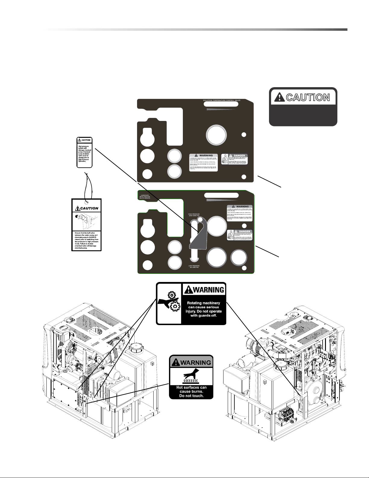
Safety Labels
The following WARNING LABELS are found on your cleaning unit. These labels point out important Warnings and
Cautions which should be followed at all times. Failure to follow warnings and cautions could result in fatality,
personal injury to yourself and/or others, or property damage. Follow these instructions carefully! DO NOT remove
these labels.
NOTE: If at any time the labels become illegible, promptly replace them.
CAUTION
Caution label
P/N 86186510
UNLEADED FUEL ONLY.
E85 FUEL WILL DAMAGE
INSTALLED EQUIPMENT.
Caution Label
P/N 86352580
Installation on
vehicle fuel door.
Caution Tag
P/N 86186500
VACUUM
LUBRICATION
WARM
WATER OUTLET
WATER INLET
ENGINE
OIL DRAIN
TEMPERATURE
BALANCE ORIFICE
CHEMICAL
CHECK
VALVE
LOW
PRESSURE
SOLUTION
SCREEN
LOW
PRESSURE
SOLUTION
OUTLETS
CARPET AND
UPHOLSTERY
SOLUTION
Warning label
P/N 86186520
HOT
LOW PRESSURE
SOLUTION REGULATOR
SOLUTION REGULATOR
HIGH PRESSURE
WARM
HIGH PRESSURE
SOLUTION OUTLET
Front lower panel decal
(Low Pressure)
P/N 86179470
Front lower panel decal
(High Pressure)
P/N 86179480
Caution label
P/N 86012220
86352170 EVEREST
9

Installation
Dealer Responsibility
Your distributor from whom you purchased this mobile
cleaning unit is responsible for correct installation of
this machine. The dealer is also responsible for initial
training of your operators and maintenance personnel
in proper operation and maintenance of this unit.
V e hicle Requirements
1. The unit should NOT be mounted in any motor
vehicle of less than 3/4 ton capacity.
DO NOT exceed the vehicle’s axle weight limit.
Include the console, full tanks, accessories, and
operators in calculations.
2. If mounting in a trailer, make certain that trailer is
rated for the total weight of UNIT AND TRAILER.
Electric or hydraulic brakes should be provided,
and a strict compliance with any State and Federal
vehicle laws must be maintained.
3. The vehicle tires should have a load rating above
the combined vehicle and unit weight.
4. We do not recommend using flooring materials that
absorb water. This could result in rust and
corrosion of the vehicle floor.
5. Padding under rubber floor mats should be
removed before installing this unit.
6. We highly recommend using a drip tray under
console (Part #86055040).
7. If using a trailer, console should be positioned so
that it balances properly with respect to axle. Ten
percent (10%) of the overall unit weight should be
on tongue.
Example: If loaded trailer weight is 2,000 lbs.,
tongue weight needs to be a minimum of 200 lbs.
to tow properly .
10
86352170 EVEREST

Installation
Lifting Unit Onto Vehicle
Since the console weighs approximately 1150 lbs., we
recommend using a forklift to lift unit onto vehicle.
Position forks under unit from front and make CERT AIN
that forks are spread to insert into frame slots.
Positioning Unit In Vehicle
Because vehicles vary in size and openings, individuals
have their own preference as to where they want their
units installed. We strongly recommend a side door
installation for this and DO NOT recommend a rear
door installation.
1. Enough space should be provided to assure
adequate engine ventilation and room for service
and maintenance.
2. The unit with waste tank and accessories must
NOT exceed vehicle's axle weight limit. An empty
100 gallon waste tank and console weighs 1300
lbs.
3. DO NOT position the console closer than 12" from
bottom of driver and passenger seats.
NOTE: For individuals who wish to make an
engineering layout prior to positioning unit, refer to
“Dimensional Data” illustrations for waste tank and
console dimensions.
Bolting Down Unit And Waste Tank
When positioning waste tank with respect to console,
hook up the vacuum hose from blower to waste tank.
This will ensure that waste tank is positioned correctly.
Proceed once unit and waste tank are positioned in
vehicle in desired location.
Before drilling any mounting holes in vehicle floor,
make certain that when drilling, you will not do any
damage to fuel tank, fuel lines, or any vital component
which might affect operation or safety of vehicle.
1. Using console and waste ta nk mounting holes a s a
template, drill six 13/32" diameter holes for
mounting console and six more 13/32" diameter
holes for mounting waste tank.
2. Using installation hardware kit:
a. Insert six 3/8-16 x 2" hex head cap screws with
flat washers through mounting holes in console,
and six 3/8-16 x 2" hex head cap screws with flat
washers through mounting holes in waste tank.
b. Install mounting plates underneath vehicle floor.
c. Screw 3/8-16 hex head locknuts on mounting
screws and tighten them until console and waste
tank are firmly secured to vehicle floor.
86352170 EVEREST
11

Installation
2'-8
1
2
"
3'-4
3
4
"
3'-11
1
8
"
4'-3
1
8
"
4'-4
1
8
"
1'-1
5
8
"
10
5
8
"
5
5
16
"
5'-6
1
2
"
3'-2
1
16
"
4'-5
13
16
"
1
1
2
"
1'-9
1
2
"
6
5
8
"
Layout with 100 Gallon Waste Tank
12
86352170 EVEREST

Installation
Waste Tank To Console Connection
NOTE: Before connecting any hoses to the waste
tank, make certain the hose clamps are on each
hose.
1. Connect the section of 4.5" I.D. internal vac hose to
the 4.5” diameter vac outlet tube on the waste ta nk
and to the vacuum pump relief valve on the
console. It may be necessary to cut this hose to fit.
Tighten the hose clamps.
2. Connect the 2” I.D. waste removal hose to the 2”
diameter tube at the bottom of the waste tank.
Connect other end to 2” tube on the Pre-Filter Box.
Tighten the hose clamps.
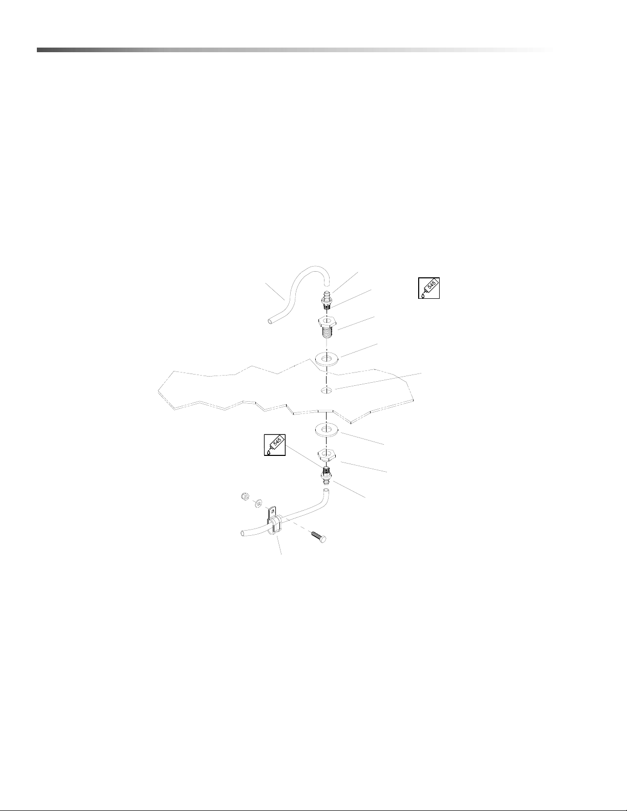
3. Connect the 3/16 blue hose from the water box
temperature relief valve to the 1/4 fitting (pointed
downward) on the waste tank that does not have a
spray jet installed inside the tank.
4. Connect the console engine shut-off cord to th e
waste tank level sensor cord.
5. Connect the 3/16 blue hose from the Flow Setup
V alve to the other 1/4 fitting (poin ted downward) on
the waste tank that has a spray jet installed inside
the tank.
Fuel Pump Assembly Installation
Before drilling the fuel line holes in the vehicle
floor, make certain that when drilling you will not do
any damage to the fuel tank(s), fuel lines, brake
lines, heat shields, or any other vital component
which might affect the operation or safety of the
vehicle.
Do not mount this assembly, any hoses or components near the catalytic converter, exhaust, or any
areas of high temperature. Avoid any contact with
moving parts, areas of high temperature, brak e
lines, fuel lines, muffler, catalytic converter, or
sharp objects.
1. Determine the mounting location of the fuel system
assembly. Mount bottom of box parallel to the
ground and side perpendicular. Ensure that the
power cord length will support the mounting
location. Mount the pump as low as possible while
still being protected by the frame from road
hazards. The pump end with the electrical connections is the discharge end. Additional mounting
holes are provided to allow for different mounting
options.
2. Cut a 6" piece of 5/16 fuel hose and connect from
the outlet side of the fuel filter to the inlet side of
the fuel pump. Use supplied hose clamps and
fasten securely.
NOTE: On the high-pressure pump supplied with the
EFI unit, add 2-3 drops of lubricating oil to the inlet
side of the fuel pump to protect the pump during initial
startup.
3. Prior to drilling, check to ensure that the cord
length will support the location of the hole. Drill a
5/8" hole in the vehicle floor for routing the fuel
pump power cord to the truckmount console and
install the hole grommet. Drill a 1-3/8" hole in the
vehicle floor for routing the electronic fuel pressu re
regulator cord to the truckmount console.
4. Do not connect the power cords to the truckmount
console wiring harness until installation is
complete.
86352170 EVEREST
13
Installation
BULKHEAD ADAPTER
BULKHEAD NUT
HOSEBARB
HOSEBARB
HOSE MOUNTING CLAMPS
FUEL HOSE
VEHICLE FLOOR
5/8" DIA HOLE
LOCTITE
FUEL PRESSURE REGULATOR
FUEL HOSE FROM
BULKHEAD GASKET
BULKHEAD GASKET
TO CONSOLE
USE AS NEEDED
Van Bulkhead Installation
1. Select a location on the vehicle floor to drill the hole for the bulkhead adapter. This location should be situated
in a position that eliminates the possibility of fuel line contact by either the operator(s) or accessories during the
working hours or maintenance periods. Make certain that the supplied hoses will reach the location and work
with the configuration you choose.
2. Drill a 5/8" (.625) diameter hole through the ve hicle fl oo r at the ins tallation poin t cho se n for the bulkhe ad .
3. Install the 1/8 NPT bulkhead adapter by inserting the adapter an d tightening the nut o n the opposite side of th e
van floor.
4. Install (1) 1/8P x 5/16 push-on hosebarb fitting on to the bulkhead (inside van).
5. Attach the 5/16" fuel hose from the console to the hosebarb fitting on the bulkhead. DO NOT USE HOSE
CLAMPS AT THIS CONNECTION.
14
86352170 EVEREST
Installation
CONNECTOR
CHECK VALVE
5/16" SUPPLY HOSE
HOSE MOUNTING CLAMP
FRONT OF VAN
BULKHEAD
BUSHINGS
ELECTRICAL CORDS
PUMP ASSEMBLY
ELECTRICAL FUEL
USE AS NEEDED
5/16" SUPPLY HOSE
FUEL SUPPLY
RETURN TO VEHICLE
FROM VEHICLE
FUEL SUPPLY
FUEL FLOW
FUEL FILTER
1/4" RETURN HOSE
Fuel Supply & Return Line Installation
(Underneath Van)
1. Spray th e inside of the supplied 90 degree plastic barbed fitting with water displacing lubricant. Push plastic
fitting onto the return tube on filler neck adapter tube until fitting securely snaps into place.
2. Measure and cut a length of 5/16" fuel hose and connect to the plastic barbed fitting on the return tube of the
filler neck adapter tube. Connect other end of hose to 1/4 x 5/16 brass hose adapter and attach adapter to 1/4"
fuel hose from electronic fuel pressure regula to r. Fasten securely using supplied hose clam ps.
3. Install (1) 1/8P x 5/16 push-on hosebarb fitting on to the bulkhea d adapter.
4. Measure and cut a length of 5/16" fuel hose and connect between the outlet side of the electronic fuel pressure
regulator and the 1/8P x 5/16 push-on hosebarb fitting at the bulkhead. DO NOT USE HOSE CLAMPS AT
THIS CONNECTION.
NOTE: Fuel tap kit installation instructions are found with appropriate fuel tap kit. Refer to Fuel Tap Kit
Information Sheet (86349940)
86352170 EVEREST
15

Installation
Battery Connection
Dangerous Acid, Explosive Gases! Batteries
contain sulfuric acid. To prevent acid burns, avoid
contact with skin, eyes, and clothing.
Batteries produce explosive hydrogen gas while
being charged. To prevent a fire or explosion,
charge batteries only in well-ventilated areas. Keep
sparks, open flames, and other sources of ignition
away from the battery at all times. Keep batteries
out of the reach of children. Remove all jewelry
when servicing batteries.
Before disconnecting the negative (- ) ground cable,
make sure all switches are OFF. If ON, a spark will
occur at the ground cable terminal which could
cause an explosion if hydrogen gas or gasoline
vapors are present. When disconnecting the
battery, ALWAYS disconnect the negative (-)
terminal FIRST.
1. Attach the red positive (+) battery cable from the
console starter solenoid to the positive (+) terminal
on the battery and tighten the holding nut.
2. Next, attach the black negative (-) battery cable
from the console ground to the negative (-) terminal
on the battery and tighten the holding nut.
Electrical Wiring
Ensure all electrical wiring and battery cables are free
from contact with any metal edge. Engine vibration
could cause metal edge to cut wiring and possibly
result in a fire. Be aware of where battery cables are
run.
Fire Extinguisher
We recommend that a fire extinguisher, preferably
rated for A, B, & C type fires, be installed inside the
vehicle.
16
86352170 EVEREST

Technical Specifications
Item Dimension / Capacity
Operations
Engine speed
Solution pump rpm 1357 rpm
Vacuum pump rpm 3125 rpm
Water flow rate 5 GPM (maximum)
Solution pump pressure (low pressure) 1200 PSI (maximum)
Solution pump pressure (high pressure) (Optional) 3000 PSI (maximum)
Vacuum relief valve 13" Hg
Waste tank capacity 100 gallons
Console weight (Model 408 & HP 408) 1065 lbs
Console weight (Model 650 & HP 650) 1150 lbs
Console weight (with waste tank & waste tank accessories)
(Model 408 & HP 408)
Console weight (with waste tank & waste tank accessories)
(Model 650 & HP 650)
Torque Values
2200 rpm (high speed)
900 rpm (idle speed)
1215 lbs
1300 lbs
Engine pulley 360 inch lbs 30 foot/lbs
Vacuum pump hub 300 inch/lbs 25 foot/lbs
86352170 EVEREST
17
Operations
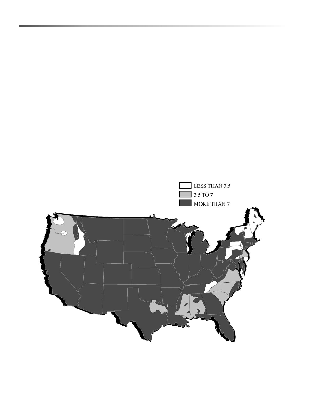
Water Requirements
Hard water deposits will adversely affect the plumbing
and heat exchange systems on this unit. The map
below will give you an idea of where areas of high water
hardness may occur. However, any water supply
obtained from a well is almost always hard water and a
water softener will be needed to protect your equipment.
NOTE: Equipment malfunction or component failure
caused by hard water scaling is NOT covered under
the warranty.
If you are operating this unit in an area where the unit
will be using water in which the hardness exceeds
3-1/2 grains, we highly recommend a suitable water
softener be installed. If using a water softener, it must
have a five (5) GPM (or greater) flow capacity without
any hose constrictions.
Using a water softener will reduce maintenance and
decrease down time caused by hard water scaling. It
will also allow cleaning chemicals to be more effective
in lower concentrations.
If you require a water softener , your dealer has a model
to meet your needs. Please contact your nearest
distributor for information, price, and availability.
18
86352170 EVEREST

Operations
Fuel Requirements
Use unleaded gasoline ONLY. DO NOT use any
gasoline additives. We recommend the use of clean,
fresh, unleaded gasoline intended for automotive use.
High-octane gasoline should NOT be used with the
engine on this unit. This unit is not compatible with E-85
fuel.
Engine Oil Requirements
Use high quality detergent oil of at least API (American
Petroleum Institute) service class SH. NOTE: Using
less than service class SH oil or extending oil change
intervals longer than recommended can cause engine
damage. The recommended SAE viscosity grade is
10W-40 or 15W-40 for regular oil. It is recommended
that a good quality synthetic oil be used after the first 25
hour break-in period to extend the service interval to
150 hours. Oils rated for high mileage engines have
been shown to help keep internal engine components
clean and keep seals and other rubber components
pliable, increasing service life. Synthetic oils of the
following viscosities are recommended: 10W-30, 10W40, 15W-50 and 20W-50. Higher viscosity oils should
be used in high temperature operating conditions and
lower viscosity oils should be used in cooler temperature operating conditions.
Chemical Requirements
This cleaning unit, due to its chemical injection pump
design, can be used with a variety of water-diluted
chemical compounds (either acidic or alkaline),
depending on the job to be done. However, to obtain
optimum results with this unit, we recommend using the
PROCHEM line of chemicals. For information on using
the cleaning compounds, refer to the PROCHEM
chemical manual.
Electronic Fuel Injection System
This unit is equipped with the latest port fuel Electronic
Fuel Injection (EFI) technology. The EFI technology
provides more effective fuel distribution and improved
power management through the use of an electronic
"brain" called the electronic control unit (ECU). The
ECU also provides improved engine emissions through
more effective combustion of the fuel/air mixture. The
fuel system, engine set up, and exhaust system are
systems approved by the Environmental Protection
Agency (EP A). Any alteration or modification to the
system must receive approval from the EPA.
86352170 EVEREST
19

Operations
EMISSION CONTROL
LABEL
SERIAL
NUMBER
FUEL PUMP
FUEL FILTER
CATALYTIC
CONVERTER
SERIAL NUMBER
Emission Control Information
The Zenith Power Products (ZPP) Emission control
labels are located on the valve cover of the engine near
the oil fill cap, and on the side of the catalytic converter.
The catallytic converter is located behind the heat
shield cover.
Date Stamp Location
When referring to an engine for assistance from your
dealer, Proche m, or ZPP please identify your engine b y
the serial # and date code stamped on the surface on
the back of the engine block, approximately where indicated.
Fuel Pump And Filter
Your Everest console was shipped to the dealer with a
specific fuel pump and fuel filter. Ensure that ONLY
these items are used in the installation of your unit.
The system is much more sensitive to unwanted
material in the fuel stream. Contamination of the fuel
stream may clog the injectors and adversely affect
performance. Please be sure to adhere to the filter
maintenance schedule located in the Operations
Section of this manual.
20
86352170 EVEREST

Operations
T rouble Codes
A feature of the ZPP 416 ECM is that DTC's (Diagnostic Trouble Codes) can be displayed to a technician to indicate
what historic faults are present without requiring the use of a personal computer. The DTC's can be flashed over th e
MIL output while the RS232 serial receive input (PC RX) is grounded . This input may be grounded a t the diagnostic
connector (pin A-brown/white wire). This connector is located behind the intake manifold near the front cylinder.
Once the ECM recognizes that the user is requesting flash codes, ignition key on-engine off, it will flash or blink a
leader code (111) x 3 times in a row. If the machine has been shut down due to a full waste tank you will also
observe flash code 552 (DTC1552) and 554 (DTC1554). Af ter the leader code has been flashed for 3 times, the first
flash code in the active faults category will be flashed at the same rate. This will repeat depending on the number
of faults retained in memory. Once all faults have been flashed the leader flash code (111) will be repeated. The
codes are retained in memory. Once any issue is resolved and the machine started-ru n-stopped for 3 times without
a fault detected the light will go out on the 4th start. If an issue has not been resolved the light will remain on and
another code stored in history.
History faults will clear automatically after 20 start-run-stop cycles if the fault has not been detected.
DTC/
#
Pcode
Leader/Trailer Code 111
1 P0016
2 P0091 Fuel Pressure low voltage 94 4 Yes 291
3 P0092 Fuel Pressure high voltage 94 3 Yes 292
4 P0107 MAP Signal open or shorted to ground 106 4 Yes 127
5 P0108 MAP signal shorted high 106 16 Yes 128
6 P0112 IAT signal Low/Shorted to GND 105 4 Yes 112
7 P0113 IAT signal High/Open 105 3 Yes 113
8 P0116 ECT higher than warning threshold 110 15 Yes 116
9 P0117 ECT Sensor Low/Shorted Input 110 4 Yes 117
10 P01 18 ECT Sensor High/Open Input 110 3 Yes 118
11 P0121 TPS1 voltage lower than TPS2 voltage 51 1 Yes 121
12 P0122 Throttle Position Signal 1 low voltage 51 4 Yes 122
13 P0123 Throttle Position Signal 1 high voltage 51 3 Yes 123
14 P0134 Pre-Cat O2 Signal No Activity 724 10 Yes 134
15 P0154 Post-Cat O2 Signal No Activity 520208 10 Yes 154
16 P0171 Gasoline bank 1 A/F is lean (adaptive learn) 520200 0 Yes 171
17 P0172 Gasoline bank 1 A/F is rich (adaptive learn) 520200 1 Yes 172
18 P0182 Gasoline Fuel Temp Low Voltage 174 4 Yes 182
19 P0183 Gasoline Fuel Temp High Voltage 174 3 Yes 183
22 P0217 ECT higher than engine shutdown threshold 1 10 0 Yes 217
23 P0219 Engine Over speed Condition 515 15 Yes 219
24 P0221 TPS1 voltage higher than TPS2 voltage 51 0 Yes 221
25 P0222 Throttle Position Signal 2 low voltage 520251 4 Yes 222
CRANK or CAM could not synchronize during
start
Fault Description
CAN
SPN
636 8 Yes 216
CAN
FMI
Turns on
MIL?
MIL Flash
Code
86352170 EVEREST
21

Operations
DTC/
#
Pcode
Fault Description
CAN
SPN
CAN
FMI
T urns on
MIL?
MIL Flash
Code
26 P0223 Throttle Position Signal 2 high voltage 520251 3 Yes 223
27 P0261 Injector 1 Low/Open 651 5 Yes 261
28 P0262 Injector 1 High/Short 651 6 Yes 262
29 P0264 Injector 2 Low/Open 652 5 Yes 264
30 P0265 Injector 2 High/Short 652 6 Yes 265
31 P0267 Injector 3 Low/Open 653 5 Yes 267
32 P0268 Injector 3 High/Short 653 6 Yes 268
33 P0270 Injector 4 Low/Open 654 5 Yes 269
34 P0271 Injector 4 High/Short 654 6 Yes 271
35 P0326 Knock signal excessive or erratic 731 2 Yes 326
36 P0327 Knock signal open or not present 731 4 Yes 327
37 P0336 CRANK signal noise 636 2 Yes 336
38 P0337 No CRANK signal 636 4 Yes 337
39 P0341 CAM signal noise 723 2 Yes 341
40 P0342 No CAM signal 723 4 Yes 342
41 P0420 Catalyst inactive on gasoline 520211 10 Yes 421
42 P0524 Engine Oil Pressure Too Low 100 1 Yes 524
43 P0562 Battery Voltage Low 168 17 Yes 562
44 P0563 Battery Voltage High 168 15 Yes 563
45 P0601 Microprocessor failure - FLASH 628 13 Yes 621
46 P0604 Microprocessor failure - RAM 630 12 Yes 624
47 P0606 Microprocessor failure - COP 629 31 Yes 626
48 P0615 Starter relay coil open 1321 5 Yes 615
49 P0616 Starter relay control short to GND 1321 4 Yes 616
50 P0617 Starter relay coil short to 12V 1321 3 Yes 617
51 P0642 5V Reference #1 voltage low 1 079 4 Yes 642
52 P0643 5V reference #1 voltage high 1079 3 Yes 643
53 P0650 Malfunction Indicator Lamp open 1213 5 Yes 651
54 P0652 5V Reference #2 voltage low 1080 4 Yes 652
55 P0653 5V Reference #2 voltage high 1080 3 Yes 653
56 P0685 Power relay coil open 1485 5 Yes 685
57 P0686 Power relay short to GND 1485 4 Yes 686
58 P0687 Power relay short to 12V 1485 3 Yes 687
22
86352170 EVEREST

Operations
DTC/
#
Pcode
63 P1155 Closed-loop gasoline bank 1 A/F is too lean 520204 0 Yes 155
64 P1156 Closed-loop gasoline bank 1 A/F is too rich 520204 1 Yes 156
86 P1551 Aux Digital Input 1 High (Float Switch Voltage Hig h) - - Yes 1551
87 P1552
88 P1553
89 P1554
94 P1612 Watchdog processor blocked outputs (RTI 1) 629 31 Yes 712
95 P1613 Microprocessor failure - RTI 2 P0629 P0031 Yes 713
96 P1614 Microprocessor failure - RTI 3 P0629 P0031 Yes 714
97 P1615 Microprocessor failure - A/D P0629 P0031 Yes 715
98 P1616 Microprocessor failure - Interrupt P0629 P0031 Yes 716
99 P1644 MIL control short to GND P1213 P0004 No 644
100 P1645 MIL control short to 12V P1213 P0003 No 645
101 P2111 Unable to reach Lower TPS P0051 P0007 Yes 211
102 P2112 Unable to reach higher TPS P0051 P0007 Yes 212
110 P2300 Ignition coil A low current P1268 P0005 Yes 411
111 P2301 Ignition coil A high current P1268 P0006 Yes 412
112 P2303 Ignition coil B low current P1269 P0005 Yes 421
113 P2304 Ignition coil B high current P1269 P0006 Yes 422
AUX DIGITAL INPUT 1 low voltage-force idle-waste
tank full.
Aux Digital Input 2 High (Float Switch Voltage High
Engine Shut Down) 1553
AUX DIGITAL INPUT 2 low voltage-after 15 secondsengine shut-down-waste tank full
Fault Description
CAN
SPN
520222 3 Yes 552
--Yes1553
520223 4 Yes 554
CAN
FMI
T urns on
MIL?
MIL Flash
Code
OBD = On Board diagnostics (Nomenclature)
DTC = Diagnostic Trouble Code
MIL = Malfunction Indicator Light
TPS1 = Throttle Position Sensor
EGO = Exhaust Gas Oxygen
ECT = Engine Coolant Temperature
86352170 EVEREST
CAM = Cam Sensor Input
CAN = Controller Ares Network
CPS = Crank Position Sensor
MAP = Manifold Absolute Pressure
Pcode= Powertrain Code
23

Operations
UPPER CONTROL
PANEL
PANEL
LOWER CONTROL
FILTER BOX
13
12
11
10
9
8
7
6
5
4
3
2
1
O
p
e
r
a
t
i
o
n
.
H
i
g
h
P
r
e
s
s
u
r
e
c
l
o
s
e
d
p
r
i
o
r
t
o
v
a
l
v
e
m
u
s
t
b
e
p
u
m
p
i
s
o
l
a
t
i
o
n
p
u
m
p
.
C
h
e
m
i
c
a
l
d
a
m
a
g
e
c
h
e
m
i
c
a
l
s
y
s
t
e
m
w
i
l
l
H
i
g
h
p
r
e
s
s
u
r
e
Components
24
LOWER CONTROL PANEL
86352170 EVEREST

Operations
Lower Control Panel
1. Lubrication Cup
The lubrication cup allows lubricant spray to reach
the vacuum blower.
2. Warm Wa te r Outlet
The warm water outlet allows the cleaning technician to drain warm water from the water box for
mixing chemical.
3. Water Inlet
This quick connect allows the water supply hose to
be connected to the unit.
4. Engine Oil Drain
The engine oil drain plug is removed to allow the
engine oil to be drained.
5. Solution Outlets
The solution outlets are the connecting point for the
high pressure solution hoses. These outlets are
quick disconnects that allow hoses to be plugged
into the unit.
6. Pressure System Valve (Option)
This lever when in the up position actuates the
high-pressure system and regulator. When in the
down position the low pressure cleaning system
and regulator are actuated.
7. High Pressure Solution Regulator (HP Only)
The high pressure regulator sets the pressure of
the pressure washing circuit. This spring loaded
valve can be adjusted up or down. The pressure is
increased by turning the valve clockwise, or
reduced by turning the valve counterclockwise.
(This valve must be maintained in accordance with
this manuals maintenance table.)
8. High Pressure Solution Outlet (Option)
The high-pressure solution outlet is the connecting
point for the high-pressure washing hose. This
outlet is a quick disconnect that allows the
pressure washing hose to be plugged into the unit.
9. Low Pressure Solution Regulator
The pressure regulator sets the pressure of the
solution system. This spring loaded valve can be
adjusted up or down. The pressure is increased by
turning the valve clockwise, or reduced by turning
the valve counterclockwise. (This valve must be
maintained in accordance with this manuals maintenance table.)
10. Solution Screen
The solution screen is located on the front of the
machine. The function of this screen is to trap
foreign particles from exiting the machine and
plugging the orifices of the cleaning tools. This
screen is part of the machine maintenance
cleaning.
11. Chemical Check Valve
The chemical check valve allows chemicals to
enter the system and travel in a singular direction
to the wand. The chemical check valve prevents
chemicals from traveling upstream into the solution
system of the unit.
12. Temperature Balance Orifice
The temperature balance orifice helps to balance
and stabilize the solution temperature within the
system.
13. Solution Temperature Control Lever
This lever directs hot engine and blower exhaust
gases through or around the heat exchangers.
86352170 EVEREST
25

Operations
3
1
2
4
18
5
17
6
16
15
14
7
13
8
12
11
10
9
15
20
10
8
Upper Control Panel
26
86352170 EVEREST

Operations
Upper Control Panel
1. Service Engine Soon (Amber)
This light, when flashing, signals a problem with
the unit. When this occurs, troubleshooting is
required.
2. Solution Temperature Gauge
This gauge measures the temperature of the
cleaning solution as it exits the machine.
3. Panel Light
This light is useful if the machine is used in a poorly
lit area or night use. It is helpful in reading the
instruments and gauges.
4. Waste Tank Full Indicator Light (Red)
This indicator light is activated when the waste tank
is full. This unit is equipped with a slow down
feature. This feature will help to protect the engine
from damage by causing a slow down for 15
seconds prior to shutting down the engine. When
this indicator light is on, it indicates that the waste
tank must be emptied before the unit can be
brought back into service.
NOTE: Never dispose of wastewater in storm drains,
waterways or on ground areas. Always dispose of
waste in accordance with local state and federal law.
5. Vacuum Gauge
This gauge indicates in inches of mercury how
much vacuum the system is producing at any given
time.
6. Waste Pumpout
This switch actuates the optional waste pumpout.
7. Ignition Switch
The ignition switch controls the power for the
machine. To turn the machine on, rotate the key
clockwise until the starter engages the engine.
When machine is running let off the switch and
engine will continue to run. To turn power off,
rotate key counter cl ockwise to stop position,
engine will then stop.
8. Circuit Breakers
These serve to protect the circuits from electrical
spike and over loads and protects wires from
damage and fire.
9. Flow Setup Valve
This valve allows solution to move through the
machine and chemical to be injected simulating the
cleaning process. This allows the operator to set
the chemical flow level without connecting tools to
the machine. It is also useful in troubleshooting.
10. 12 Volt Outlet
The 12 volt outlet is used for accessories such as
auxiliary lighting.
11. Chemical Metering Valve
The chemical metering valve regulates the amount
of chemical that is injected into the system.
Clockwise rotation of the knob closes the valve.
Counter clockwise rotation opens the valve,
allowing more chemical to enter the system.
12. Flow Meter
The flow meter is a gauge to indicate how much
liquid chemical is being introduced in the water
system. The quantity can be increased by turning
the chemical metering valve knob counter clockwise.
13. Chemical Selector Valve
This valve allows the chemical to circulate through
the chemical system with little or no restriction. It
also purges out air that may be trapped in the lines
and cavities of the chemical pump. By turning the
valve counter clockwise the injection system is
enabled.
86352170 EVEREST
27

Operations
2
1
14. Hour Meter
The hour meter records the number of hours the unit
has run. This serves as a time recorder for servicing
the machine.
15. Engine Speed Control
This serves to set the engine speed and operating
parameters. The 'Low', 'Medium' and 'High' settings
are set for upholstery cleaning, single wand cleaning,
and dual wand cleaning respectively.
16. Solution Pump Switch
This switch serves to energize the magnetic clutch to
turn the
activating the pump and counter clockwise for deactivating the pump.
solution pump on or off. Turn clockwise for
Filter Box
17. Auxiliary Water Tank Pump Switch
The Auxiliary Water Tank Pump Switch is used to
actuate an optional fresh water demand pump
18. Solution Pressure Gauge
This gauge registers the amount of pressure in the
system.
1. Vacuum Inlets
The vacuum inlets serve as the connecting point for
vacuum hoses.
2. Waste Tank Drain
This allows the waste tank to be emptied. Must be
closed for operation.
28
86352170 EVEREST
 Loading...