

Page 1

LEGEND GT
MOBILE CLEANING UNIT
Operating Instructions (ENG)
MODELS: LEGEND GT
1.001-119.0
86313050 - BP
10/24/13
Read instructions before operating the machine.
Page 2

Left intentionally blank
Page 3

Warranty Registration
Thank you for purchasing a Prochem product. Warranty registration is quick and easy.
Your registration will allow us to serve you better over the lifetime of the product.
To register your product go to :
www.prochem.com/WarrantyRegistration.aspx
For customer assistance:
1-800-776-2436
Model:
Date of Purchase:
Serial Number:
Dealer:
Address:
Phone Number:
Sales Representative:
Machine Data Label
Overview
Welcome…and congratulations on the purchase of your Mobile Cleaning Unit. This instruction manual is a guide
for operating and servicing your unit. Read this manual completely before installing or operating this unit.
This unit offers you personal convenience. All of your instrumentation and controls have been positioned to give
you easy access for operation and daily maintenance.
Proper operation and service are essential to the efficient functioning of this unit. When maintained correctly, this
unit will have a long, trouble-free life.
The service methods described in this manual are explained in such a manner that servicing may be performed
accurately and safely. Proper service varies with the choice of procedure, the skill of the mechanic, and the tools or
parts available. Before attempting any repair, make certain that you are thoroughly familiar with this equipment and
are equipped with the proper tools. Any questions pertaining to operating or servicing this unit should be directed
to your nearest dealer.
THIS UNIT MUST BE INSTALLED BY THE DEALER FROM WHOM YOU PURCHASED IT IN ACCORDANCE
WITH THE PRESCRIBED INSTALLATION PROCEDURES.
Information in this document is subject to change without notice and does not represent a commitment on the part
of PROCHEM.
86313050 LEGEND GT
1
Page 4

Table of Contents
Overview . . . . . . . . . . . . . . . . . . . . . . . . . . . . . . . . . 1
Machine Data Label . . . . . . . . . . . . . . . . . . . . . . . . . 1
Table of Contents . . . . . . . . . . . . . . . . . . . . . . . . . . . 2
Receiving Your Unit . . . . . . . . . . . . . . . . . . . . . . . . . 4
Acceptance of Shipment . . . . . . . . . . . . . . . . . . . . . 4
Equipment List . . . . . . . . . . . . . . . . . . . . . . . . . . . . . 4
How to Use This Manual . . . . . . . . . . . . . . . . . . . . . 5
Safety
IMPORTANT SAFETY INSTRUCTIONS. . . . . . . . . 6
Hazard Intensity Level . . . . . . . . . . . . . . . . . . . . . . . 8
Safety Labels . . . . . . . . . . . . . . . . . . . . . . . . . . . . . . 9
Installation
Dealer Responsibility . . . . . . . . . . . . . . . . . . . . . . . 10
Vehicle Requirements . . . . . . . . . . . . . . . . . . . . . . 10
Lifting Unit Onto Vehicle . . . . . . . . . . . . . . . . . . . . 10
Positioning Unit In Vehicle . . . . . . . . . . . . . . . . . . . 10
Bolting Down Unit And Waste Tank. . . . . . . . . . . . 11
Electrical Wiring . . . . . . . . . . . . . . . . . . . . . . . . . . . 11
Layout with 60 Gallon Waste Tank . . . . . . . . . . . . 12
Layout with 60 Gallon Waste Tank & Optional
Auxiliary Water Tank . . . . . . . . . . . . . . . . . . . . . 13
Layout with 100 Gallon Waste Tank . . . . . . . . . . . 14
Layout with 100 Gallon Waste Tank & Optional
Auxiliary Water Tank . . . . . . . . . . . . . . . . . . . . . 15
Waste Tank To Console Connection . . . . . . . . . . . 16
Fuel Pump Assembly Installation. . . . . . . . . . . . . . 16
Van Bulkhead Installation . . . . . . . . . . . . . . . . . . . 17
Fuel Supply & Return Line Installation. . . . . . . . . . 18
Battery Connection . . . . . . . . . . . . . . . . . . . . . . . . 19
Initial Operational Settings . . . . . . . . . . . . . . . . . . . 20
Operations
Technical Specifications . . . . . . . . . . . . . . . . . . . . 21
Fuel Requirements. . . . . . . . . . . . . . . . . . . . . . . . . 22
Engine Oil Requirements . . . . . . . . . . . . . . . . . . . . 22
Altitude Requirements . . . . . . . . . . . . . . . . . . . . . . 22
Chemical Requirements. . . . . . . . . . . . . . . . . . . . . 22
Water Requirements . . . . . . . . . . . . . . . . . . . . . . . 23
Components. . . . . . . . . . . . . . . . . . . . . . . . . . . . . . 24
Vacuum System. . . . . . . . . . . . . . . . . . . . . . . . . . . 27
Water Pumping and Heat Transfer System . . . . . . 28
Heat Exchanger . . . . . . . . . . . . . . . . . . . . . . . . . . . 28
Chemical Injection System. . . . . . . . . . . . . . . . . . . 30
Pre-Run Inspection / Setup . . . . . . . . . . . . . . . . . . 31
Check For Adequate Fuel . . . . . . . . . . . . . . . . . . . 31
Remove Tools From Vehicle . . . . . . . . . . . . . . . . . 31
Water Supply Connection . . . . . . . . . . . . . . . . . . . 31
High Pressure Solution Hose. . . . . . . . . . . . . . . . . 31
Vacuum Hose . . . . . . . . . . . . . . . . . . . . . . . . . . . . 31
Filters . . . . . . . . . . . . . . . . . . . . . . . . . . . . . . . . . . . 31
Priming the Chemical Pump . . . . . . . . . . . . . . . . . 32
Waste Pump (Optional) . . . . . . . . . . . . . . . . . . . . . 32
Cleaning. . . . . . . . . . . . . . . . . . . . . . . . . . . . . . . . . 32
Upholstery Cleaning. . . . . . . . . . . . . . . . . . . . . . . . 33
Shutdown and Daily Maintenance . . . . . . . . . . . . . 33
De-Flooding Operations . . . . . . . . . . . . . . . . . . . . . 33
Freezing Protection . . . . . . . . . . . . . . . . . . . . . . . . 33
Overheating Protection . . . . . . . . . . . . . . . . . . . . . 33
Winterizing the Unit . . . . . . . . . . . . . . . . . . . . . . . . 34
Removing Anti-Freeze From the Unit . . . . . . . . . . 35
2 86313050 LEGEND GT
Page 5

Table of Contents
Maintenance
Service Schedule . . . . . . . . . . . . . . . . . . . . . . . . . .36
Key Checkpoints. . . . . . . . . . . . . . . . . . . . . . . . . . .38
External Fuel Pump Maintenance. . . . . . . . . . . . . .38
Chemical Supply System Maintenance . . . . . . . . .38
Heat Exchanger System Maintenance . . . . . . . . . .38
Vacuum Pump Maintenance. . . . . . . . . . . . . . . . . .39
Engine. . . . . . . . . . . . . . . . . . . . . . . . . . . . . . . . . . .39
Vacuum Pump . . . . . . . . . . . . . . . . . . . . . . . . . . . .40
Solution Pump. . . . . . . . . . . . . . . . . . . . . . . . . . . . .41
Vacuum Inlet Filter (in Waste Tank) . . . . . . . . . . . .41
Vacuum Relief Valve. . . . . . . . . . . . . . . . . . . . . . . .41
Vacuum Pump Drive Belts . . . . . . . . . . . . . . . . . . .41
Solution Pump Drive Belts . . . . . . . . . . . . . . . . . . .42
Float Valve (Water Box) . . . . . . . . . . . . . . . . . . . . .42
Waste Tank Float Valve . . . . . . . . . . . . . . . . . . . . .42
Waste Tank Strainer Basket . . . . . . . . . . . . . . . . . .42
Waste Tank Vacuum Inlet Filter . . . . . . . . . . . . . . .42
Check Valve (Outlet). . . . . . . . . . . . . . . . . . . . . . . .43
Chemical Pump. . . . . . . . . . . . . . . . . . . . . . . . . . . .43
Chemical and Temperature Control Valves . . . . . .43
Pressure Regulator. . . . . . . . . . . . . . . . . . . . . . . . .43
Vacuum Hoses . . . . . . . . . . . . . . . . . . . . . . . . . . . .43
High Pressure Solution Hoses . . . . . . . . . . . . . . . .43
Optional Waste Pump-Out . . . . . . . . . . . . . . . . . . .43
General Service Adjustments. . . . . . . . . . . . . . . . .44
Engine Speed . . . . . . . . . . . . . . . . . . . . . . . . . . . . .44
Check Valve (Solution Outlet). . . . . . . . . . . . . . . . .44
Water Box. . . . . . . . . . . . . . . . . . . . . . . . . . . . . . . .44
Chemical Pump. . . . . . . . . . . . . . . . . . . . . . . . . . . .44
Solution and Vacuum Pump Drive Belts. . . . . . . . .44
Packing Nut Adjustments for Chemical Valves. . . .45
Pressure Regulator. . . . . . . . . . . . . . . . . . . . . . . . .45
Troubleshooting . . . . . . . . . . . . . . . . . . . . . . . . . . .46
Parts
Frame . . . . . . . . . . . . . . . . . . . . . . . . . . . . . . . . . . 52
Side Panel. . . . . . . . . . . . . . . . . . . . . . . . . . . . . . . 54
Control Panel - Upper . . . . . . . . . . . . . . . . . . . . . . 56
Control Panel - Upper . . . . . . . . . . . . . . . . . . . . . . 58
Engine. . . . . . . . . . . . . . . . . . . . . . . . . . . . . . . . . . 60
Vacuum Pump . . . . . . . . . . . . . . . . . . . . . . . . . . . 62
Solution Pump. . . . . . . . . . . . . . . . . . . . . . . . . . . . 64
Heat Exchanger . . . . . . . . . . . . . . . . . . . . . . . . . . 68
Pressure Regulator & Temperature Control Valve 70
Solution Outlet . . . . . . . . . . . . . . . . . . . . . . . . . . . 72
Water Box . . . . . . . . . . . . . . . . . . . . . . . . . . . . . . . 74
60 Gallon Waste Tank - From Serial Number *(1) 76
60 Gallon Waste Tank - To Serial Number *(1) . . 78
100 Gallon Waste Tank . . . . . . . . . . . . . . . . . . . . 80
Fuel Pump. . . . . . . . . . . . . . . . . . . . . . . . . . . . . . . 82
Battery Floor Mount . . . . . . . . . . . . . . . . . . . . . . . 84
Chemical Jug Floor Mount . . . . . . . . . . . . . . . . . . 86
Wiring Diagram . . . . . . . . . . . . . . . . . . . . . . . . . . . 88
Hose Diagram. . . . . . . . . . . . . . . . . . . . . . . . . . . . 89
Options
Hose Accessories . . . . . . . . . . . . . . . . . . . . . . . . . 92
Exhaust - Optional . . . . . . . . . . . . . . . . . . . . . . . . 94
Automatic Pumpout - Dual Diaphragm - Optional. 96
Wand - Titanium Six Jet - Optional . . . . . . . . . . . . 98
Wand - Ergo Titanium Six Jet - Optional. . . . . . . 100
Wand - Quad Jet - Optional . . . . . . . . . . . . . . . . 102
Wand - Tri Jet -Optional . . . . . . . . . . . . . . . . . . . 104
Stair Tool - Optional . . . . . . . . . . . . . . . . . . . . . . 106
Upholstery Tool - Optional . . . . . . . . . . . . . . . . . 108
Shelf Assembly - Optional. . . . . . . . . . . . . . . . . . 110
Water Tank Dual with Demand Pump - Optional 112
Water Tank - Demand Pump - Optional . . . . . . . 114
Auxiliary Water Tank with Pump-Optional . . . . . 116
Auxiliary Water Tank - Optional . . . . . . . . . . . . . 118
Hose Reel - Optional. . . . . . . . . . . . . . . . . . . . . . 120
Motorized Hose Reel - Tank - Optional. . . . . . . . 122
Motorized Hose Reel - Optional . . . . . . . . . . . . . 124
E Z - Charge Water Softener - Tank & Tray -
Optional . . . . . . . . . . . . . . . . . . . . . . . . . . . . 126
E Z - Charge Water Softener - Filter - Optional . 128
E Z - Charge Water Softener - Brine System - . . . .
Optional . . . . . . . . . . . . . . . . . . . . . . . . . . . . 130
Serial Numbers . . . . . . . . . . . . . . . . . . . . . . . . . . 132
86313050 LEGEND GT 3
Page 6

Receiving Your Unit
Acceptance of Shipment
Every part of your cleaning unit was carefully checked,
tested, and inspected before it left our manufacturing
plant. Upon receiving the unit, make the following
acceptance check:
1. The unit should not show any outward signs of
damage. If damaged, notify the common carrier
immediately.
2. Check your equipment and packing list. The standard cleaning unit should arrive equipped with the
following items (unless otherwise specified) and
any optional accessories which were ordered:
Equipment List
1. Console.
2. Waste tank.
3. Fuel pump assembly.
4. 100 ft. of 2” vacuum hose.
5. 1 vacuum hose connector.
6. 100 ft. of 1/4” high pressure hose with quick
connects.
7. 50 ft. water supply hose with quick connect.
8. Installation bolting kit.
9. Installation mounting plates.
10. Operation and service manuals for engine, solution
pump, and vacuum pump.
4
86313050 LEGEND GT
Page 7

How to Use This Manual
Model:
Date of Purchase:
Serial Number:
Dealer:
Address:
Phone Number:
Sales Representative:
This manual contains the following sections:
The HOW TO USE THIS MANUAL section will tell you
how to find important information for ordering correct
repair parts.
Parts may be ordered from authorized dealers. When
placing an order for parts, the machine model and
machine serial number are important. Refer to the
MACHINE DATA box which is filled out during the
installation of your machine. The MACHINE DATA box
is located on the inside of the front cover of this manual.
The model and serial number of your machine is
located approximately where shown
The SAFETY section contains important information
regarding hazardous or unsafe practices for this
machine. Levels of hazards are identified that could
result in product damage, personal injury, or severe
injury resulting in death.
• How to Use This Manual
•Safety
• Installation
• Operations
• Maintenance & Service
•Parts List
The INSTALLATION section contains information on
how to properly install the unit in your vehicle.
The OPERATIONS section is to familiarize the operator
with the operation and function of the machine.
The MAINTENANCE section contains preventive maintenance to keep the machine and its components in
good working condition. They are listed in this general
order:
•Engine
• Vacuum Pump
• Solution Pump
• Drive Belts, Pulleys & Hubs
• Chemical Pump
• Hoses
• Exhaust Heat Exchanger
• General Service Adjustments
• Machine Troubleshooting
The PARTS LIST section contains assembled parts
illustrations and corresponding parts list. The parts lists
include a number of columns of information:
• REF – column refers to the reference number
• PART NO. – column lists the part number for
• PRV NO. – reference number.
• QTY – column lists the quantity of the part used
• DESCRIPTION – column is a brief description
• SERIAL NO. FROM – If this column has an (*)
• NOTES – column for information not noted by
NOTE: If a service or option kit is installed on your
machine, be sure to keep the KIT INSTRUCTIONS
which came with the kit. It contains replacement parts
numbers needed for ordering future parts.
NOTE: The manual part number is located on the
lower left corner of the front cover.
86313050 LEGEND GT
on the parts illustration.
the part.
in that area of the machine.
of the part.
and a Reference number, see the SERIAL
NUMBERS page in the back of your manual. If
column has two asterisk (**), call manufacturer
for serial number. The serial number indicates
the first machine the part number is applicable
to. The main illustration shows the most current
design of the machine. When a boxed illustration is shown, it displays the older design.
the other columns.
5
Page 8

Safety
IMPORTANT SAFETY INSTRUCTIONS
When using this machine, basic precaution
must always be followed, including the following:
READ ALL INSTRUCTIONS BEFORE USING THIS MACHINE.
These symbols mean WARNING or CAUTION. Failure to follow warnings and
cautions could result in fatality, personal injury to yourself and/or others, or
property damage. Follow these instructions carefully!
Read the operator's manual before installing or starting this unit. Failure to adhere to instructions could result
in severe personal injury or could be fatal.
Operate this unit and equipment only in a well-ventilated area. Exhaust fumes contain carbon monoxide which
is an odorless and deadly poison that can cause severe injury or fatality. DO NOT run this unit in an enclosed area.
DO NOT operate this unit where the exhaust may enter any building doorway, window, vent, or opening of any type.
Gasoline is extremely flammable and its vapors can explode if ignited. Store gasoline only in approved
containers, in well-ventilated, unoccupied buildings away from sparks or flames. Never carry any gasoline or
flammable material in the vehicle. Fumes may accumulate inside the vehicle and ignite, causing an explosion.
DO NOT store any type of flammable material in the vehicle.
This unit must be operated with the vehicle or trailer doors open in order to ensure adequate engine ventilation.
DO NOT operate engine if gasoline is spilled. Avoid creating any ignition until the gasoline has been cleaned up.
Never use gasoline as a cleaning agent.
DO NOT place hands, feet, hair, or clothing near rotating or moving parts. Avoid any contact with moving
parts! Rotating machinery can cause injury or fatality.
Never operate this unit without belt guards. The high speed moving parts, such as belts and pulleys, should be
avoided while this unit is running. Severe injury, damage, or fatality may result.
DO NOT service this unit while it is running. The high-speed mechanical parts as well as high temperature
components may result in severe injury or severed limbs.
Never touch electrical wires or components while the engine is running. They can be sources of electrical
shock.
Engine components can get extremely hot from operation. To prevent severe burns, DO NOT touch these
areas while the engine is running or immediately after the engine is turned off.
DO NOT touch any part of the exhaust system while this unit is running. Severe burns may result.
Before servicing this unit, allow it to cool down. This will prevent burns from occurring.
Water under high pressure at high temperature can cause burns, severe personal injury, or fatality. Shut
down machine, allow to cool down, and relieve system of all pressure before removing valves, caps, plugs,
fittings, filters, and bolts.
Always wear hearing protection when unit is running. Always comply with your company’s Personal
Protection Equipment (PPE) plan. Always comply with local noise ordinance when operating units.
6
86313050 LEGEND GT
Page 9

Safety
DO NOT leave the vehicle engine running while operating this unit.
Dangerous Acid, Explosive Gases! Batteries contain sulfuric acid. To prevent acid burns, avoid contact with skin,
eyes and clothing. Batteries produce explosive hydrogen gas while being charged. To prevent a fire or explosion,
charge batteries only in well ventilated areas. Keep sparks, open flames, and other sources of ignition away from
the battery at all times. Keep batteries out of the reach of children. Remove all jewelry when servicing batteries.
Before disconnecting the negative (-) ground cable, make sure all switches are OFF. If ON, a spark will occur at the
ground cable terminal which could cause an explosion if hydrogen gas or gasoline vapors are present. When
disconnecting the battery, ALWAYS disconnect the negative (-) terminal FIRST.
DO NOT smoke around the unit. Gas fumes may accumulate and be ignited. The battery is also extremely flammable. This will prevent possible explosions.
DO NOT damage the vehicle in any manner during installation. When routing fuel lines DO NOT place the
hose in any location where damage may occur to the hose or vehicle. Avoid any contact with moving parts, areas
of high temperature, brake lines, fuel lines, muffler, catalytic converter, or sharp objects.
Use only ProChem supplied fuel installation kits. Ensure to use the kit specific for the truckmount model and
van model being used. When traversing the vehicle floor with fuel lines, always use a bulkhead adapter. This will
prevent leakage and ensure that the hose is not punctured by vehicle vibration abrasion.
DO NOT exceed your vehicle's weight limit. The console with empty 60 gallon waste tank and accessories
weighs approximately 810 lbs (900 lbs. if mounted on water tank). Make certain to account for any additional accessories in your weight and balance calculations. Make certain that the vehicle has the correct axle rating. This will
prevent unsafe vehicle driving conditions.
We require high-back seats on all vehicles in which units are to be installed for head and neck protection.
We recommend using a metal partition between the seats and equipment.
DO NOT operate this unit without the water supply attached and turned on. The solution pump and other vital
components may be seriously damaged if this unit is permitted to operate dry without water.
Keep your vehicle work area clean. Wands, stair tools, and other accessories must be securely fastened before
driving the vehicle.
All high pressure hoses must be rated for 3000 PSI at 250°F. Thermoplastic hoses do not meet these specifications and should not be used. Severe burns and injury may result if the hoses do not meet these requirements.
The winterizing loop hose assembly, Part # 86260700, is for winterizing use only. If used improperly, live
steam may escape from this hose, causing it to whip around. Burns or injury may result.
Make certain that you receive complete training by the distributor from whom you purchased this unit.
This unit uses high pressure and temperature. Improper or irresponsible use may result in serious injury.
Do not modify this unit in any manner. Improper modification can cause severe personal injury or fatality.
CALIFORNIA PROPOSITION 65 WARNING: Engine exhaust from this product contains chemicals known to the
State of California to cause cancer, birth defects, or other reproductive harm. Running with out adequate water
supply could damage water pump. Ensure always to have an adequate water supply.
86313050 LEGEND GT
7
Page 10

Safety
The following symbols are used throughout this guide as indicated in their descriptions:
Hazard Intensity Level
There are three levels of hazard intensity identified by signal words - WARNING and CAUTION and FOR SAFETY.
The level of hazard intensity is determined by the following definitions:
WARNING - Hazards or unsafe practices which COULD result in severe personal injury or death.
CAUTION - Hazards or unsafe practices which could result in minor personal injury or product or property damage.
FOR SAFETY: To Identify actions which must be followed for safe operation of equipment.
Report machine damage or faulty operation immediately. Do not use the machine if it is not in proper operating
condition. Following is information that signals some potentially dangerous conditions to the operator or the equipment. Read this information carefully. Know when these conditions can exist. Locate all safety devices on the
machine. Please take the necessary steps to train the machine operating personnel.
FOR SAFETY:
DO NOT OPERATE MACHINE:
Unless Trained and Authorized.
Unless Operation Guide is Read and understood.
In Flammable or Explosive areas.
In areas with possible falling objects.
WHEN SERVICING MACHINE:
Avoid moving parts. Do not wear loose clothing; jackets, shirts, or sleeves when working on the machine. Use
ProChem approved replacement parts.
8
86313050 LEGEND GT
Page 11

Safety
CAUTION
Safety Labels
The following WARNING LABELS are found on your cleaning unit. These labels point out important Warnings and
Cautions which should be followed at all times. Failure to follow warnings and cautions could result in fatality,
personal injury to yourself and/or others, or property damage. Follow these instructions carefully! DO NOT remove
these labels.
NOTE: If at any time the labels become illegible, promptly replace them.
Caution Label
P/N 86352580
Installation on vehicle fuel door.
Caution Label
P/N 86186530
Lower Front Panel Decal
with warning labels
P/N 86309420
Warning Label
P/N 86186520
86313050 LEGEND GT
9
Page 12

Installation
Dealer Responsibility
Your distributor from whom you purchased this mobile
cleaning unit is responsible for correct installation of
this machine. The dealer is also responsible for initial
training of your operators and maintenance personnel
in proper operation and maintenance of this unit.
Vehicle Requirements
1. The unit should NOT be mounted in any motor
vehicle of less than 1/2 ton capacityor 3/4 ton if
equipped with one or more auxiliary fresh water
tanks.
DO NOT exceed the vehicle’s axle weight limit.
Include the console, full tanks, accessories, and
operators in calculations.
2. If mounting in a trailer, make certain that trailer is
rated for the total weight of UNIT AND TRAILER.
Electric or hydraulic brakes should be provided,
and a strict compliance with any State and Federal
vehicle laws must be maintained.
3. The vehicle tires should have a load rating above
the combined vehicle and unit weight.
4. We do not recommend using flooring materials that
absorb water. This could result in rust and
corrosion of the vehicle floor.
5. Padding under rubber floor mats should be
removed before installing this unit.
Lifting Unit Onto Vehicle
Since console weighs approximately 600 lbs. pounds,
(690 lbs. if mounted on water tank) we recommend
using a forklift to lift unit onto vehicle. Position forks
under unit from front and make CERTAIN that forks are
spread to insert into frame slots.
Positioning Unit In Vehicle
Because vehicles vary in size and openings, individuals
have their own preference as to where they want their
units installed. We strongly recommend a side door
installation for this and DO NOT recommend a rear
door installation.
1. Enough space should be provided to assure
adequate engine ventilation and room for service
and maintenance.
2. The unit with waste tank and accessories must
NOT exceed vehicle's axle weight limit. An empty
60 gallon waste tank and console weighs 810 lbs
(900 lbs. if mounted on water tank).
3. DO NOT position the console closer than 12" from
bottom of driver and passenger seats.
NOTE: For individuals who wish to make an
engineering layout prior to positioning unit, refer to
"Dimensional Data" illustrations for waste tank and
console dimensions.
4. Be sure to consider all accessories and their
required space prior to positioning the console and
waste tank.
6. We highly recommend using a drip tray under
console (Part #86050370, or Part # 86050380 for
units mounted on a water tank).
7. If using a trailer, console should be positioned so
that it balances properly with respect to axle. Ten
percent (10%) of the overall unit weight, should be
on tongue.
Example: If loaded trailer weight is 2,000 lbs.,
tongue weight needs to be a minimum of 200 lbs.
to tow properly.
10
86313050 LEGEND GT
Page 13

Installation
Bolting Down Unit And Waste Tank
NOTE: When positioning waste tank with respect to
console, hook up the vacuum hose to waste tank.
This will ensure that waste tank is positioned
correctly. Proceed once unit and waste tank are
positioned in vehicle in desired location.
Before drilling any mounting holes in vehicle floor,
make certain that when drilling, you will not do any
damage to fuel tank, fuel lines, or any vital
component which might affect operation or safety
of vehicle.
1. Using console and waste tank mounting holes as a
template, drill six 13/32" diameter holes for
mounting console and six more 13/32" diameter
holes for mounting waste tank.
2. Using installation hardware kit:
a. Insert six 3/8-16 x 2" hex head cap screws with
flat washers through mounting holes in console,
and six 3/8-16 x 2" hex head cap screws with flat
washers through mounting holes in waste tank.
Electrical Wiring
Ensure all electrical wiring and battery cables are free
from contact with any metal edge. Engine vibration
could cause metal edge to cut wiring and possibly
result in a fire. Be aware of where battery cables are
run.
b. Install mounting plates underneath vehicle floor.
c. Screw 3/8-16 hex head locknuts on mounting
screws and tighten them until console and waste
tank are firmly secured to vehicle floor.
86313050 LEGEND GT
11
Page 14
Installation
39
1
2
"
33
7
8
"
CONSOLE
39
3
8
"
WASTE TANK
38
1
8
" WASTE TANK
31
31
32
" CONSOLE
22
3
8
"
6X Ø7/16" X 5/8" SLOT
37
1
8
"
2X 1
1
2
"
2X 6
3
16
"
2X 12
3
8
"
2X 2
3
32
"
2X 12"
2X 24"
59
1
2
"
6X Ø
13
32
"
TOP VIEW
FRONT VIEW
AND WASTE TANK ARE ALIGNED
ENSURE THAT VAC INLETS ON CONSOLE
1
2
"
11
16
"
7
1
4
"
15
3
32
"
7
1
2
"
Layout with 60 Gallon Waste Tank
12
86313050 LEGEND GT
Page 15

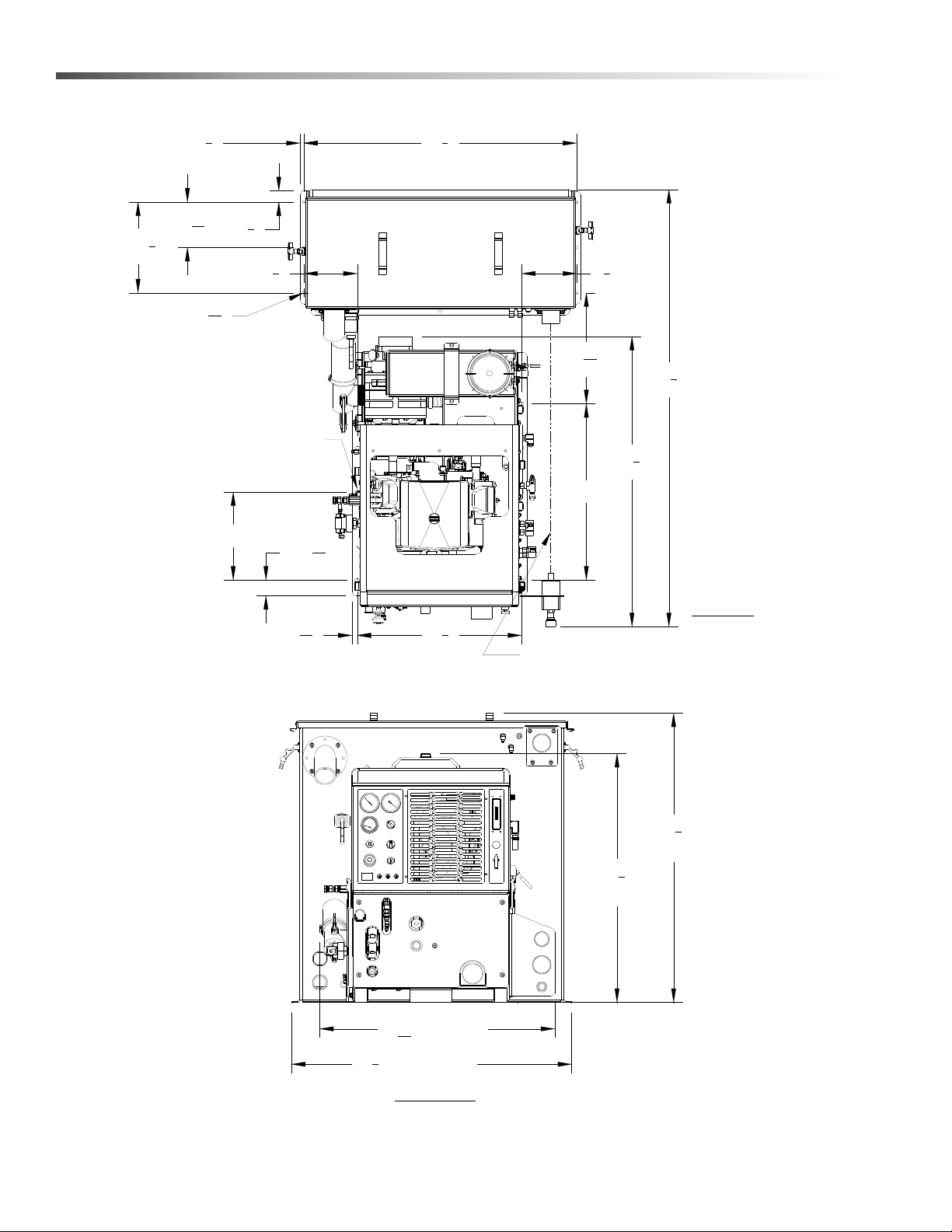
67
13
16
"
LENGTH
38
3
8
"
WASTE
TANK
AUXILIARY WATER TANK
FRONT VIEW
TOP VIEW
WASTE TANK
CONSOLE
38
1
8
"
AND WASTE TANK ARE ALIGNED
ENSURE THAT VAC INLETS ON CONSOLE
2X 40
13
32
"
6X Ø
13
32
"
2X 12
3
8
"
2X 6
3
16
"
2X 1
11
16
"
1
2
"
37
1
8
"
11
16
"
3
7
8
" MIN.
6X Ø
3
8
"
34
25
32
"
2X 20
3
16
"
47
1
8
"
OVERALL
HEIGHT
40
17
32
"
7
21
32
"
4
9
16
"
7
21
32
"
2
7
32
"
Installation
Layout with 60 Gallon Waste Tank & Optional Auxiliary Water Tank
86313050 LEGEND GT
13
Page 16

9X Ø7/16" X 5/8" SLOT
19
1
4
"
7
1
2
"
15
3
32
"
2X 12
3
8
"
2X 12"
59
1
2
"
LENGTH
ENSURE THAT VAC INLETS ON CONSOLE
AND WASTE TANK ARE ALIGNED
22
3
8
"
11
16
"
2X 6"
2X 1
11
16
"
2X 6
3
16
"
49
1
8
"
1
2
"
6X Ø
13
32
"
TOP VIEW
CONSOLE
WASTE TANK
33
3
8
"
CONSOLE
HEIGHT
50
1
8
"
FRONT VIEW
38
3
8
"
WASTE
TANK
31
31
32
"
2X 24"
4
31
32
"
Installation
Layout with 100 Gallon Waste Tank
14
86313050 LEGEND GT
Page 17

2X 12
3
8
"
2X 40
13
32
"
67
13
16
"
LENGTH
ENSURE THAT VAC INLETS ON CONSOLE
AND WASTE TANK ARE ALIGNED
34
25
32
"
11
16
"
2X 20
3
16
"
2X 1
11
16
"
2X 6
3
16
"
49
1
8
"
1
2
"
50
1
8
"
6X Ø
3
8
"
3
31
32
" MIN.
6X Ø
13
32
"
TOP VIEW
CONSOLE
AUXILIARY WATER TANK
WASTE TANK
47
1
8
"
OVERALL
HEIGHT
40
17
32
"
FRONT VIEW
38
3
8
"
WASTE
TANK
16
9
16
"
2
7
32
"
7
21
32
"
Layout with 100 Gallon Waste Tank & Optional Auxiliary Water Tank
Installation
86313050 LEGEND GT
15
Page 18

Installation
Waste Tank To Console Connection
NOTE: Before connecting any hoses to the waste
tanks, make certain the hose clamps are on each
hose.
1. Connect the section of 2-7/8" I.D. internal vac hose
between the 2-7/8" dia. vac outlet tube on the
waste tank and the vacuum pump relief valve on
the console. It may be necessary to cut this hose
to fit. Tighten the hose clamps.
2. Connect the 2" I.D. waste removal hose to the 2"
dia. tube at the bottom corner of the waste tank.
Cut to desired length. Install brass ball valve on
other end.
3. Connect 2-1/2" I.D. hose between waste tank
vacuum inlet (upper right of waste tank) and
vacuum inlet on lower side panel of console.
4. Connect the 3/16" blue hose from the water box to
the lower flare fitting (angled downward) on the
waste tank.
5. Run the 5/8" water box overflow hose through the
van floor. Prior to drilling through the van floor,
ensure that no damage will occur in drilling area.
Ensure that you are in compliance with all local
environmental laws.
6. Connect the console engine shut-off cord to the
waste tank level sensor cord.
7. Connect the 3/16" blue hose from the solution
temperature control valve to the other flare fitting
(angled downward) on the waste tank.
Fire Extinguisher
We recommend that a fire extinguisher, preferably
rated for A, B, & C type fires, be installed inside the
vehicle.
Fuel Pump Assembly Installation
Before drilling the fuel line holes in the vehicle
floor, make certain that when drilling you will not do
any damage to the fuel tank(s), fuel lines, brake
lines, heat shields, or any other vital component
which might affect the operation or safety of the
vehicle.
Do not mount this assembly, any hoses or components near the catalytic converter, exhaust, or any
areas of high temperature. Avoid any contact with
moving parts, areas of high temperature, brake
lines, fuel lines, muffler, catalytic converter, or
sharp objects.
1. Determine the position where the fuel pump
assembly will be mounted. Check to ensure that
the power cord length will support the mounting
location. The pump should be mounted as low as
possible and still be protected by the frame from
road hazards. Mount the fuel pump with the
discharge side of the pump higher than the
suction side to eliminate the possibility of
trapped air in the pump. Additional mounting
holes are provided to allow for different mounting
options.
2. Drill a 5/8" (.625) diameter hole in the vehicle floor
for routing the fuel pump power cord to the truckmount console. Check to ensure that the cord
length will support the location of the hole.
3. Route the power cord and install the hole grommet.
4. Do not connect the power cord to the truckmount
console wiring harness until installation is
complete.
16
86313050 LEGEND GT
Page 19

Installation
TO CONSOLE
USE AS NEEDED
BULKHEAD ADAPTER
BULKHEAD NUT
HOSEBARB ELBOW
HOSEBARB ELBOW
HOSE MOUNTING CLAMPS
FUEL HOSE
HOSE CLAMP
VEHICLE FLOOR
5/8" DIA HOLE
LOCTITE
BYPASS FUEL FILTER
FUEL HOSE FROM
BULKHEAD GASKET
BULKHEAD GASKET
Van Bulkhead Installation
1. Select a location on the vehicle floor to drill the hole for the bulkhead adapter. This location should be situated
in a position that eliminates the possibility of fuel line contact by either the operator(s) or accessories during the
working hours or maintenance periods. Make certain that the supplied hoses will reach the location and work
with the configuration you choose.
2. Drill a 5/8" (.625) diameter hole through the vehicle floor at the installation point chosen for the bulkhead.
3. Install the 1/8 NPT bulkhead adapter by inserting the adapter and tightening the nut on the opposite side of the
van floor.
4. Attach the 1/8 NPT x 1/4 Hosebarb 90 degree elbow to the bulkhead inside the van to connect the fuel system
to the console.
5. Attach the 1/4" fuel hose from the console to the 1/4” Hosebarb 90 degree elbow on the bulkhead.
86313050 LEGEND GT
17
Page 20

Installation
CHECK VALVE
5/16" SUPPLY HOSE
BYPASS FUEL FILTER
HOSE MOUNTING CLAMP
FRONT OF VAN
BULKHEAD CONNECTOR
BUSHING
ELECTRICAL CORD
PUMP ASSEMBLY
ELECTRICAL FUEL
USE AS NEEDED
5/16" SUPPLY HOSE
5/16" SUPPLY HOSE
FUEL SUPPLY
RETURN TO VEHICLE
FROM VEHICLE
FUEL SUPPLY
FUEL FLOW
FUEL FILTER
1/4" RETURN HOSE
Fuel Supply & Return Line Installation
(Underneath Van)
1. Attach the 1/8 NPT x 5/16 Hosebarb 90 degree elbow to the bulkhead adapter underneath the van to be used
for the fuel supply line.
2. Cut to length the 6' piece of 5/16" 50 PSI fuel hose used for the supply line from:
a. Bulkhead adapter to the outlet side of the bypass fuel filter.
b. Inlet side of the bypass fuel filter to the discharge side of the fuel pump.
c. Inlet side of the fuel pump to the outlet side of the inline fuel filter.
3. Cut to length the 6' piece of 1/4" fuel line to connect the bypass fuel filter with the fuel tank return using the
appropriate fuel tap kit.
4. Check all hose clamps for tightness.
NOTE: Fuel tap kit installation instructions are found with appropriate fuel tap kit. Refer to Fuel Tap Kit
Information Sheet (8.634-994.0)
18
86313050 LEGEND GT
Page 21

Battery Connection
Dangerous Acid, Explosive Gases! Batteries
contain sulfuric acid. To prevent acid burns, avoid
contact with skin, eyes, and clothing.
Batteries produce explosive hydrogen gas while
being charged. To prevent a fire or explosion,
charge batteries only in well-ventilated areas. Keep
sparks, open flames, and other sources of ignition
away from the battery at all times. Keep batteries
out of the reach of children. Remove all jewelry
when servicing batteries.
Before disconnecting the negative (-) ground cable,
make sure all switches are OFF. If ON, a spark will
occur at the ground cable terminal which could
cause an explosion if hydrogen gas or gasoline
vapors are present. When disconnecting the
battery, ALWAYS disconnect the negative (-)
terminal FIRST.
Installation
1. Attach the red positive (+) battery cable from the
console starter solenoid to the positive (+) terminal
on the battery and tighten the holding nut.
2. Next, attach the black negative (-) battery cable
from the console ground to the negative (-) terminal
on the battery and tighten the holding nut.
86313050 LEGEND GT
19
Page 22

Installation
Initial Operational Settings
NOTE: Due to temperature and altitude changes, the
optimal settings for each truckmount must be
adjusted after installation. Failure to make these
adjustments may lead to poor unit performance and
premature component failure.
Vacuum Pump
The maximum vacuum pressure obtainable at full
throttle should be 13"Hg. If the unit is drawing a
stronger vacuum (at full sealed suction) than 13" Hg,
adjust the vacuum relief spring to 13" Hg.
Engine
Set RPM Values as shown below. Refer to Engine
Operation Manual for adjustment instructions.
THROTTLE LOAD RPM*
Idle None 1400 rpm
Full
Full None 2950 rpm
*±50 rpm tolerance
13" Hg. Vacuum
500 psi pressure
2850 rpm
20
86313050 LEGEND GT
Page 23

Technical Specifications
ITEM DIMENSION/CAPACITY
Engine speed
Water pump rpm 1680 rpm
Vacuum pump rpm 3385 rpm
Water flow rate 3.5 GPM (maximum)
Solution pump pressure 1200 PSI (maximum)
Vacuum relief valve 13” Hg
Waste tank capacity 60 gallons / 100 gallons
Console weight 600 lbs. (690 lbs. If mounted on water tank)
Console weight with:
60 gallon waste tank & accessories
Console weight with:
60 gallon waste tank, water tank & accessories
Console weight with:
100 gallon waste tank & accessories
Console weight with:
100 gallon waste tank, water tank & accessories
TORQUE VALUES
Engine rear / vac pump pulley 25 foot lbs
Engine front / water pump pulley 9 foot lbs
2950 rpm
1400 rpm (idle speed)
810 lbs. with empty waste tank
1252 lbs. with full waste tank
900 lbs. with empty waste and water tanks
1342 lbs. with full waste tank, and empty water tank
1842 lbs. with full waste and water tanks
820 lbs. with empty waste tank
1445 lbs. with full waste tank
910 lbs. with empty waste tank
1535 lbs. with full waste tank, and empty water tank
2035 lbs. with full waste and water tanks
Operations
86313050 LEGEND GT
21
Page 24

Operations
Fuel Requirements
Use unleaded gasoline ONLY. DO NOT use any
gasoline additives. We recommend the use of clean,
fresh, unleaded gasoline intended for automotive use.
High octane gasoline should NOT be used with the
engine on this unit. These engines are NOT designed
to use E-85 or Flex Fuels.
Engine Oil Requirements
Use high quality detergent 10W-30 oil of at least API
(American Petroleum Institute) service class SG, SH,
SJ or higher.
NOTE: Using a lower service class oil or extending oil
change intervals longer than recommended can
cause engine damage.
NOTE: Synthetic oils meeting the listed
classifications may be used with oil changes
performed at recommended intervals. However to
allow piston rings to properly seat, a new or rebuilt
engine should be operated for at least 50 hours using
standard petroleum based oil before switching to
synthetic oil.
Altitude Requirements
Engines perform differently with increases/decreases in
altitude. Be sure to check engine speeds during initial
installation. See engine speeds in Technical Specifications section.
NOTE: To ensure correct engine operation at
altitudes above 1525 meters (5000 ft.), it may be
necessary to have an authorized dealer install a
special high altitude jet kit in the carburetor. If a high
altitude kit has been installed, the engine must be
reconverted to the original jet size, before it is
operated at lower altitudes, or overheating and
engine damage can result.
Chemical Requirements
This cleaning unit, due to its chemical injection pump
design, can be used with a variety of water-diluted
chemical compounds (either acidic or alkaline),
depending on the job to be done. However, to obtain
optimum results with this unit, we recommend using the
PROCHEM line of chemicals. For information on using
the cleaning compounds, refer to the chemical manual.
22
86313050 LEGEND GT
Page 25

Operations
Water Requirements
Hard water deposits will adversely affect the plumbing
and heat exchange systems on this unit. The map
below will give you an idea of where areas of high water
hardness may occur. However, any water supply
obtained from a well is almost always hard water and a
water softener will be needed to protect your equipment.
NOTE: Equipment malfunction or component failure
caused by hard water scaling is NOT covered under
the warranty.
If you are operating this unit in an area where the unit
will be using water in which the harness exceeds 3-1/2
grains, we highly recommend a suitable water softener
be installed. If using a water softener, it must have a
five (5) GPM (or greater) flow capacity without any hose
constrictions.
Using a water softener will reduce maintenance and
decrease down time caused by hard water scaling. It
will also allow cleaning chemicals to be more effective
in lower concentrations
If you require a water softener, your dealer has a model
to meet your needs. Please contact your nearest
distributor for information, price, and abailability.
86313050 LEGEND GT
23
Page 26

Operations
1
2
3
4
5
6
7
8
9
10
11
12
13
14
15
16
17
18
19
20
21
22
23
Components
24
86313050 LEGEND GT
Page 27

Components
Operations
1. VACUUM GAUGE
This gauge indicates in inches of mercury how
much vacuum the system is producing at any given
time.
2. SOLUTION PRESSURE GAUGE
This gauge registers the amount of pressure in the
system.
3. WASTE PUMPOUT
This switch actuates the optional waste pumpout.
4. SOLUTION TEMP GAUGE
This gauge measures the temperature of the
cleaning solution exiting the machine.
5. SOLUTION PUMP SWITCH
This switch serves to energize the magnetic clutch,
to turn the pump on and off. Turn clockwise to
activate the pump and counter clockwise for deactivating the pump.
6. CHOKE
The choke is for restricting air to the carburetor,
this enriches the fuel mixture. The primary
purpose is for starting in cold temperatures. When
the cable is pulled out air is restricted, when
pushed in the engine is in run position.
Do NOT run engine with choke pulled out.
7. IGNITION SWITCH
The ignition switch controls the power for the
machine. To turn the machine on, turn solution
pump switch counterclockwise to override and
hold. Turn key clockwise until engine starts and
release. Wait 5 seconds then release override
switch. To stop engine rotate key to OFF position.
8. THROTTLE
The throttle is used to set the speed of the engine
(rpm). The engine speed (rpm) may be increased
by releasing the collar lock, pushing in the red
button on the end of the handle, and pulling the
handle straight out. Engine speed may be changed
in smaller increments by rotating the throttle handle
clockwise or counter-clockwise. The collar lock can
be tightened to prevent the throttle from slipping
and changing the engine speed.
9. HOUR METER
The hour meter records the number of hours the
unit has run. This serves as a time recorder for
servicing the machine.
10. CIRCUIT BREAKERS
These serve to protect the circuits from electrical
spikes and over loads and protects wires from
damage and fire.
11. TEMPERATURE BALANCE ORIFICE
The temperature balance orifice helps to balance
and stabilize the solution temperature within the
system.
12. SOLUTION PRESSURE REGULATOR
The pressure regulator sets the pressure of the
solution system. This spring loaded valve can be
adjusted up or down. The pressure is increased by
turning the valve clockwise, or reduced by turning
the valve counter clockwise. (This valve must be
maintained in accordance with this manuals maintenance table.)
13. LUBRICATION CUP
The lubrication cup allows lubricant spray to reach
the vacuum blower.
86313050 LEGEND GT
25
Page 28

Operations
14. SOLUTION TEMPERATURE CONTROL
VALVE
This valve allows the operator to control the
solution temperature by bypassing hot water to the
waste tank, for low temperature cleaning such as
upholstery. Turning the valve counter clockwise
opens the valve. Turning clockwise closes the
valve and has the effect of stopping water from
bypassing.
15. CHEMICAL CHECK VALVE
The chemical check valve allows chemicals to
enter the system and travel in a singular direction
to the wand. The chemical check valve prevents
chemicals from traveling upstream into the solution
system of the unit.
16. SOLUTION OUTLET
The solution outlet is the connecting point for the
high pressure solution hoses. This outlet is a quick
disconnect that allows hoses to be plugged into the
unit.
17. SOLUTION SCREEN
The solution screen is located on the front of the
machine. The function of this screen is to trap
foreign particles from exiting the machine and
plugging the orifices of the cleaning tools. This
screen is part of the machine maintenance
cleaning.
19. WATER INLET
This quick connect allows the water supply hose to
be connected to the unit.
20. VACUUM INLETS
The vacuum inlets serve as connecting points for
vacuum hoses.
21. CHEMICAL PRIME CONTROL VALVE
This valve allows the chemical to circulate through
the chemical system with little or no restriction. It
also purges out air that may be trapped in the lines
and cavities of the chemical pump. By turning the
valve clockwise the injection system is enabled.
22. CHEMICAL METERING VALVE
The chemical metering valve regulates the amount
of chemical that is injected into the system.
Clockwise rotation of the knob closes the valve.
Counter clockwise rotation opens the valve,
allowing more chemical to enter the system.
23. FLOW METER
The flow meter is a gauge to indicate how much
liquid chemical is being introduced in the water
system. The quantity can be increased by turning
the chemical flow knob counter clockwise.
18. EXHAUST
Exhaust fumes contain carbon monoxide which is
an odorless and deadly poison that can cause
severe injury or fatality. DO NOT run this unit in an
enclosed area. DO NOT operate this unit where
the exhaust may enter any building doorway,
window, vent, or opening of any type.
26
86313050 LEGEND GT
Page 29

Operations
VACUUM
PUMP
VACUUM
SILENCER
VACUUM
RELIEF
VALVE
LEVEL SENSOR
(ENGINE SHUT-OFF SWITCH)
FILTER
HOT AIR TO
HEAT EXCHANGER
VACUUM
INLET
STRAINER
WASTE TANK
LUBRICATION
CUP
VACUUM
GAUGE
Vacuum System
The engine turning the vacuum pump generates
vacuum. The air is channeled in one side of the
vacuum pump, compressed and discharged on the
opposite side, creating airflow.
The movement of air is used to do the work necessary
for the extraction process. A vacuum nozzle applied to
the carpet surface removes moisture, dirt and spent
chemicals. These elements are conveyed back to a
separating tank utilizing hoses and the force of air.
Particles of moisture and dirt are separated in the
vacuum tank using a series of changes in direction and
velocity. The air is then filtered and rushes into the
vacuum pump.
The vacuum pump compresses and heats the incoming
air. The hot discharged air is forced down stream into a
silencer for noise abatement. After exiting the silencer,
this hot air is mixed with hot air exhaust gases from the
engine. This mixture of hot air and gases are then
forced through 3 radiators serving as heat collectors.
Heat from the engine and vacuum pump is then transferred into the plumbing system raising the water
temperature for better cleaning.
The vacuum pump speed is factory set to maximize
vacuum pressure and provide sustained system life.
Do not alter the vacuum speed outside the recommended range shown in the Technical Specifications
section.
86313050 LEGEND GT
27
Page 30

Operations
Heat Exchanger
Always wear hearing protection and proper
personal protection equipment when operating
unit.
Water Pumping and Heat Transfer System
Cold water enters the console through the water inlet.
When the water box is full the valve will automatically
shut off.
Water then flows from the water box, through the
strainer, into the solution pump. The water is pumped to
the pressure regulator manifold, which provides and
maintains the desired pressure setting.
The pressure regulator manifold includes a pulse hose,
which helps reduce pressure spikes from the pump.
A certain amount of water is by-passed from the
pressure regulator due to over pumping capacity of the
solution pump. Water that is not called for in the
cleaning process is channeled through a copper heater
core in the front of the heat exchanger box. This bypass
water circulates several times through the heater core
pre-warming the water.
The water temperature in the plumbing system is raised
for better cleaning. This happens in the heat
exchanger. The heat exchanger is made up of three
stages. These three stages are engine exhaust stage,
the mixing stage, and the pre-warming stage.
The angled rear heat exchanger core receives its heat
only from the engine exhaust gases. This core
becomes extremely hot and should not be touched
while the machine is in operation. Allow the machine to
cool down completely before attempting to service this
area.
The middle core receives its heat from the mixing of
both the engine exhaust and the vacuum pump
exhaust. The vacuum pump heats incoming air as it is
compressed. This hot air is mixed with the hot engine
exhaust gases exiting the angled rear core. This
mixture of hot air and gases is then forced through the
middle core and on through the front heat exchanger
core.
The front core continues to extract heat from the mixed
gases; but, this heat is used to pre-heat the water box
as a preliminary hot water reservoir.
The gases coming from the vacuum pump and the
engine exhaust are forced through the middle and rear
heater core creating the hottest area of the heat
exchanger box, and increasing the heat transfer to the
circulating water.
The hot water passes to the solution outlet manifold
where cleaning chemicals are injected from the
chemical pulse pump. This manifold serves as a
connecting point for the high-pressure hoses. Also a
check valve is located in this outlet manifold prohibiting
chemicals from backing up into the system.
The cleaning solution then passes through highpressure solution hoses and is distributed by the
cleaning tool to a surface that is being cleaned,
completing the water pumping and heating cycle of the
cleaning unit.
28
86313050 LEGEND GT
Page 31

SOLUTION
OUTLET
WATER
INLET
CHEMICAL
INJECTION
WASTE TANK
WATER BOX
SOLUTION PUMP
KOHLER ENGINE
HEAT EXCHANGER
CORES
TEMPERATURE
RELIEF VALVE
PRESSURE
GAUGE
CHECK VALVE
PRESSURE REGULATOR
= COLD WATER
= WARM WATER
= HOT WATER
= HOT EXHAUST AIR
TEMPERATURE
CONTROL VALVE
SOLUTION SCREEN
TEMPERATURE
BALANC E ORIFIC E
HOT AIR FROM
VACUUM PUMP
REAR
FRONT
PULSE HOSE
Operations
86313050 LEGEND GT
29
Page 32

Operations
CHEMICAL
OFF
ON
FLOW METER
PRIME
METERING VALVE
CONTROL VALVE
CHEMICAL JUG
CHEMICAL PUMP
OUTLET SCREEN
OUTLET CHECK VALVE
SOLUTION PUMP
SOLUTION OUTLET
Chemical Injection System
The chemical injection system is unique in that it
utilizes the pressure spikes generated by the high
pressure solution pump to move chemical into the main
solution stream. The high pressure spikes move the
diaphragm in the chemical pulse pump forcing small
amounts of liquid chemical to be moved in a single
direction of flow with the aid of two check valves.
The chemical is drawn from the container, and through
the flow meter, which indicates rate of flow. The
chemical then moves to the chemical pulse pump
where it is pressurized.
The chemicals flow to the chemical selector valve,
which can turn off the chemical flow or when set to
"Prime" sends it into a bypass loop to purge air from the
system, or when "CHEM" the chemical can be directed
to the metering valve. The metering valve controls the
amount of chemical that enters the solution outlet
manifold.
The manifold assembly's check valve will not allow the
chemicals to travel upstream into the plumbing system
of the unit. The chemicals are mixed there with hot
pressurized water that makes a cleaning solution. The
solution then flows to the outlets for cleaning.
30
86313050 LEGEND GT
Page 33

Operations
DANGER
TEMPER ATURE CAN CAUSE BUR NS,
SEVERE PERSONAL INJURY, OR COULD
BE FATAL. SHUT DOWN MACHINE,
ALLOW TO COOL DOW N, AND RELIEVE
SYSTEM OF ALL PRESSURE BEFORE
REMOVING VALVES, CAPS, PLUGS,
FITTING S, FILTERS AND BOL TS.
DANGER
DO NOT MODIFY
UNIT WITHOUT
WRITTEN
PERMISSION
FROM
MANUFACTURER
ROTATING
MACHINERY.
WATER UNDER
PRESSURE AT HIGH
TEMPERATURE.
IMPROPER
MODIFICATION OF
EQUIPTMENT CAN
CAUSE SEVERE
PERSONAL INJURY
OR COULD BE
Pre-Run Inspection / Setup
NOTE: Operation of this unit is simple. However, only
trained personnel should proceed.
Operate this unit and equipment only in a wellventilated area. Exhaust fumes contain carbon
monoxide, which is an odorless and deadly poison
that can cause severe injury or fatality. DO NOT
operate this unit where the exhaust may enter any
building doorway, window, vent, or opening of any
type.
Check For Adequate Fuel
Check the fuel tank to be certain there is adequate fuel
to complete the job. This unit uses approximately .75 –
1.00 gallons of fuel per hour, depending on the speed
setting.
Remove Tools From Vehicle
Remove any tools or hoses from the van, which you will
require.
High Pressure Solution Hose
Before starting the unit, connect the high pressure
solution hose to the outlet connection at the front of the
unit. Connect the cleaning tool to the pressure hose.
WATER UNDER HIGH PRESSURE AT HIGH
FATAL.
Vacuum Hose
Connect the vacuum hose to the vacuum inlet connection at the front of the unit. Connect the other end of the
vacuum hose to the cleaning tool.
Water Supply Connection
NOTE: Before connecting your water hose to the
supply faucet, flush out the faucet until the water is
free of any debris. Flush out any debris which may be
in your water inlet hose.
1. Connect the water supply hose to the water inlet
quick-connect on the right side panel of the
console. Connect the hose to the water supply
faucet.
NOTE: Never use your waste pump outlet hose as a
water inlet hose. Use only clean hoses for water inlet.
2. Turn the water supply faucet on. The water will fill
the water box.
Don't run the solution pump dry, damage may
occur and void the warranty.
In the event the pump is run dry, allow the pump to
cool down to ambient temperature before reintroducing water. Otherwise major damage may occur
and void the warranty.
86313050 LEGEND GT
Filters
Ensure all filters on machine and in waste tank are free
of debris.
31
Page 34

Operations
Priming the Chemical Pump
1. Fill chemical container and inspect chemical
strainer.
2. Insert chemical inlet and prime tubing into chemical
container.
3. Pull out engine choke, turn solution pump switch to
override and turn ignition key to start.
4. Push in engine choke after engine has started.
5. Set throttle to idle position.
6. Turn on solution pump.
7. Turn chemical control valve to prime and allow
chemical to circulate. After all air bubbles have
been removed from chemical tubing, turn the valve
to the horizontal (off) position.
8. Turn the chemical control valve to run. use the
chemical metering valve to set the chemical flow to
the desired flow rate while observing the flow meter
indicator. To accurately set the chemical flow, pull
the trigger on the cleaning tool while adjusting the
flow rate.
9. Set throttle to maximum position for quick unit heat
up.
NOTE: Do not run the machine with the port blocked
for more than 2 minutes to avoid overheating.
Once you have completed priming the chemical pump,
proceed with the cleaning operation. Your unit should
be in the correct throttle position for your cleaning
operation or extracting.
Always dispose of waste in accordance with Local,
State, and Federal laws.
Waste Pump (Optional)
1. If your unit is equipped with an automatic waste
pump, connect one end of a garden hose to the
pump-out connection and the other end to an
appropriate waste disposal.
2. Turn the pump-out switch on the control panel to
the ON position. The waste pump will operate automatically throughout the cleaning operation.
We recommend that you use a 3/4" I.D. water hose as
a waste pump outlet hose. DO NOT use a hose smaller
than 5/8" I.D.
NEVER use your automatic waste pump outlet hose as
a water inlet hose.
Cleaning
Observe the following guidelines, while cleaning:
1. Before proceeding make sure the spray tips are
functioning properly.
a. To check, hold the wand about one foot above the
surface to be cleaned and open the wand valve. A
full spray should be observed from all of the spray
tips.
b. If the spray tips are not showing a full spray pat-
tern, adjust for proper pattern, clean, or replace
spray tips, if required.
32
2. Normally chemical is applied on the push stoke of
the wand when cleaning and vacuuming is done on
the pull stroke. For heavily soiled carpets the wand
may be used in a scrubbing manner, applying
chemical in both push and pull strokes. Always finish up an area with a vacuum stroke.
3. When cleaning, keep the working opening (mouth)
flat on the surface being cleaned. Keep the wand
moving when the valve is open.
4. The unit will automatically shut-down when the
waste tank is full. This will prevent water being
drawn into the vacuum pump. If shut-down occurs,
empty the waste tank before proceeding. If shutdown occurs due to foam created by chemicals
used, add Prochem defoamer.
86313050 LEGEND GT
Page 35

Operations
Upholstery Cleaning
Upholstery tool, (See Options Section)
1. To protect fabrics, reduce solution temperature as
needed by opening the solution temperature control valve on the lower front panel. Engine speed
may also be reduced slightly to reduce heat and
vacuum.
Shutdown and Daily Maintenance
1. Close chemical metering valve.
2. Allow the unit to run for 2 minutes with the vacuum
hose disconnected to remove moisture. Spray
water displacing lubricant into the vacuum lubrication cup. This will prevent corrosion due to moisture.
3. Set engine throttle at idle position and allow the
water temperature to cool down, utilizing the temperature control valve in the open position to bleed
off residual hot water left in the system.
4. Close temperature control valve and turn off ignition switch.
5. Disconnect all hoses and tools.
6. Drain waste tank and rinse with clean water.
De-Flooding Operations
De-flooding operations involve removal of water from
carpet and flooring. This differs from normal cleaning
operations in that no water or solution is required. An
automatic waste pump-out is highly recommended for
all de-flooding operations due to the large amount of
water removal often required.
Freezing Protection
If the unit is exposed to freezing weather the water
in the unit may freeze, causing SERIOUS DAMAGE
to the unit. To avoid this, the following is recommended during the cold weather season.
When the unit is not in use, always park it in a heated
building.
While in operation, avoid long shutdowns as the unit
provides heat while running. Shut it down just prior to
leaving for the next job.
If a heated building is not available, we recommend that
you winterize the unit with anti-freeze. At present, it is
only possible to winterize units, which do not have an
auxiliary water tank. Units with auxiliary water tanks
must be stored in a heated building when not in use.
Overheating Protection
Air cooled engines rely on the flow of air over the
engine for cooling operations. Ensure that there is
sufficient air flow in the van. Never operate the unit
with all the vehicle doors closed and no alternative
ventilation system.
This unit must be operated with the vehicle or
trailer doors open in order to ensure adequate
engine ventilation.
1. Start unit.
2. Set pressure regulator at 100 psi.
3. Shut off solution pump.
4. Begin de-flooding operations.
5. Under almost all conditions, the unit will sufficiently
cool itself. If you find yourself operating in extreme
heat: Hook up a water supply; turn on the water
pump at 100 psi, and crack the temperature control
valve slightly to provide additional cooling to the
solution system.
86313050 LEGEND GT
33
Page 36

Operations
Winterizing the Unit
1. Shut off the water supply. Disconnect the water
inlet hose from the front of your console.
2. Connect all high pressure solution hoses and tools
that may have water in them.
3. Start the unit and turn solution pump on. Open the
tool valve until water pressure drops.
4. Turn off solution pump. Fill the water box with
approximately two gallons of 100% glycol base
anti-freeze.
5. Turn the solution pump switch ON.
6. Open the tool valve until anti-freeze begins to
come out of the tool. Recover ALL anti-freeze that
comes out of the tools into an approved container.
We strongly recommend that you re-cycle and reuse the anti-freeze.
Repeat this procedure with all the remaining tools. After
all tools and pressure hoses have been filled with antifreeze, disconnect and store them.
7. Turn the solution pump switch OFF. Attach the
winterizing loop hose with attachment, Part
#86260700, to the solution outlet connection and
the water inlet connection. Turn the solution pump
switch ON.
9. Prime the chemical system with 50/50 anti-freeze/
water mix. Insert the chemical inlet and prime
discharge tubes into the anti-freeze container.
Turn the chemical valve to PRIME until anti-freeze
begins to flow out of the prime hose.
10. Turn the chemical valve to the open position,
making certain that the flow meter indicates flow
and that all anti-freeze drains out of the chemical
hose into an approved container, after 30 seconds,
turn off both valves.
Allow the unit to run for approximately 3 minutes with
the winterizing loop hose attached.
8. Open temperature control valve and allow antifreeze to flow to waste tank.
34
86313050 LEGEND GT
Page 37

Operations
Removing Anti-Freeze From the Unit
1. Connect the water inlet hose to the water inlet
connection on the console. Turn the water supply
on.
2. Start unit turn on pump.
3. Connect all solution hoses and any tools which
require purging of anti-freeze to the solution outlet
connection(s).
4. Open the tool valves and drain the anti-freeze into
an approved container until the flow is clear and all
anti-freeze is purged from the tools and hoses.
5. Place the chemical prime hose into the approved
container. Submerge the chemical inlet hose in
water. Turn the chemical valve to the PRIME
position until clear water comes through the prime
hose, and then remove the prime hose from the
container.
6. Turn the chemical valve to the ON (CHEMICAL)
position. This will allow water to flow into the other
side of the system.
Once all of the anti-freeze is removed, the unit is ready
to use.
Eventually, the anti-freeze in your storage container will
become diluted with water. If the anti-freeze level drops
below 50% of the total, dispose of it and start with fresh
100% anti-freeze.
When disposing of used anti-freeze, observe local
laws and regulations. Do not drain onto the ground
or into storm drainage systems.
86313050 LEGEND GT
35
Page 38

Maintenance
Service Schedule
Engine Daily Check engine oil level. *** Fill to proper level (Do not overfill)
Vacuum Pump Daily Spray water displacing lubricant in lubrication cup at front of
console for 5 sec.
Solution Pump Daily Check oil level.** Fill to proper level (Do not overfill)
Chemical Inlet Tube Strainer Daily Check strainer for blockage, remove any debris
Vacuum Inlet Filter (In Waste Tank) Daily Clean filter, inspect, replace if damaged
Vacuum Hoses Daily Wash out with clean water
Automatic Waste Pump Daily Inspect and remove any debris or sediment
Vacuum Pump Weekly* Check oil level. Fill to proper level
Water Box Float Valve Weekly Check for proper seating and shut-off
Solution Pump Inlet Strainer Weekly* Check for debris and clean
Temperature Balance Orifice Weekly Remove, clean and check screen (as needed)
Battery Weekly* Check for proper fluid level. Fill with distilled water only
Solution Outlet Screen Weekly* Inspect and remove any debris or blockage
High Pressure Hoses 25 hrs Inspect for damage or impending damage
Pressure Regulator 50 hrs Lubricate o-rings
Pressure Regulator 50 hrs Lubricate plug behind spring
Engine 100 hrs Change engine oil and oil filter***
Battery 100 hrs* Clean battery terminals
Automatic Waste Pumpout 100 hrs Clean inlet and outlet ports
Belts/Pulleys 100 hrs Check belt wear and tension. Check pulley alignment.
Water Box Float Valve Seal 200 hrs. Inspect and replace seal as needed
Engine 200 hrs Service air cleaner elements*
Fuel Pump 200 hrs Check hose connections
Engine 200 hrs Replace fuel filter (carbureted engines)
Engine 200 hrs Check spark plugs for carbon deposits and proper gap
Chemical Valves 200 hrs Inspect and/or adjust packing nuts
Temperature Control Valve 200 hrs Inspect and/or adjust packing nuts
36
86313050 LEGEND GT
Page 39

Vacuum pump 250 hrs Lubricate bearing on pulley end with grease
Vacuum Exhaust Heat Exchanger 500 hrs Inspect cores and remove debris.
Solution Pump 500 hrs Change oil**
Pulley Set Screws & Hub Cap Screws,
Solution Pump Clutch Shaft Bolts
Drive Pulley 500 hrs Inspect, clean and check for pulley groove wear****
Drive Pulley 500 hrs Check pulley alignment****
Drive Belts 500 hrs Inspect and clean****
Drive Belts 500 hrs Check belt tension****
Chemical Pump & Check Valves 500 hrs Replace diaphragm, plastic disk and check valves.
Vacuum Lubrication Lines 500 hrs Check for line obstructions. Replace tubing if cracked or
Engine 500 hrs Replace in-line fuel filter on engine.
Engine 1000 hrs Replace spark plugs.
Chemical Pump & Check Valves 1000 hrs Replace diaphragm, plastic disk and check valves.
Check Valve (Solution Outlet) 1000 hrs Inspect, clean, and repair, if needed.
Waste Tank Shut-off Float Switch Monthly Check for debris hindering movement
Vacuum pump Yearly Drain and replace oil*****
Waste Tank Filters/Strainers Yearly Check for damage and blockage. Replace if needed.
Engine Yearly Replace air cleaner element
Engine 3 years Replace ignition wires.
500 hrs Check for proper torque values. Re-torque, if
required****
damaged
Maintenance
* Or as often as required
** Change solution pump crankcase oil after the first 50 hours
***Change engine crankcase oil and filter after the first 8 hours
****Perform drive belt, pulley and hub maintenance after the first 25 hours of operation, and then again at 100
hours
*****Tuthill Pneulube - Drain and replace oil after the first 100 hours, then drain and replace oil every 1000
hours, or once a year, whichever comes first.
86313050 LEGEND GT
37
Page 40

Maintenance
Key Checkpoints
NOTE: Initiation of a planned preventative
maintenance program will assure that your unit has
optimum performance, a long operating life, and a
minimal amount of "down" time.
External Fuel Pump Maintenance
The power plant for the unit receives fuel from the main
fuel tank of your van/truck. An external fuel pump that
provides this fuel is located on the underside of the van/
truck. Loose fittings and hose connections will cause
your unit to perform poorly. Follow the recommended
fuel pump maintenance in the Maintenance Schedule
in this manual. Refer any additional questions to your
dealer.
Chemical Supply System Maintenance
The chemical supply system pulls chemicals from your
chemical bottle utilizing a pump that works off the water
pump pulsing. Any clogged filters or loose connections
will result in a chemical supply system malfunction or a
malfunction at the cleaning tool. Maintenance of the
solution outlet check valve and screen are vital to
effective cleaning operation and minimal unit downtime.
Additionally, the hoses related to supplying water and
chemical to the outlet manifold are under high
pressures and experience thermal expansion and
contraction. Periodic inspections of these hoses for
tears, cracks, and failing connectors are necessary to
avoid unwanted leaks. To keep your chemical system
functioning properly, follow the chemical pump and
solution outlet maintenance in the Maintenance
Schedule in this manual. Refer any additional
questions to your dealer.
Heat Exchanger System Maintenance
The heat exchange system in your unit transfers
energy from the engine’s exhaust and blower discharge
air to the solution supply system. The heat transfer of
this system is highly dependent on the surface area
contact in the heat exchanger cores located in the heat
exchanger box. This surface area amount is adversely
minimized when the supplied water is not softened to
recommended levels. Hard water will result in scaling
on the inside walls of the heat exchanger tubes. It is
recommended that you use a manufacturer approved
water softener to avoid premature heat exchanger core
failure. Contact your local dealer for advice on the
water hardness levels in your area.
Additionally, the heat exchanger tubes are very
sensitive to freezing conditions. As the water freezes
during cold conditions, it expands in the heat
exchanger tubes and causes damage. Often the tubes
are cracked and require the replacement of the heat
exchanger core. Refer to the Freeze Protection instructions section in this manual. Refer any additional
questions to your dealer.
38
86313050 LEGEND GT
Page 41

Maintenance
Vacuum Pump Maintenance
(Refer to pump manufacturer’s manual for specific
maintenance instructions)
The total function of the unit is based around the performance of the vacuum pump. Heat transfer used to
raise the temperature of the solution is gained from the
air drawn by the vacuum pump and solution is removed
from the carpet with the vacuum suction of the vacuum
pump. General maintenance actions for the vacuum
pump as listed in this manual are vital to prolonged
vacuum pump operations. Daily lubrication of the
pump is required to avoid seizure of the system. Also,
waste tank filters and strainers must be maintained to
prevent unwanted debris from entering the vacuum
pump.
DO NOT service this unit while it is running. The
high-speed mechanical parts as well as high
temperature components may result in severe
injury, severed limbs, or fatality.
NOTE: Use the hour meter as a guide for coordinating
the maintenance schedule.
Engine
(Refer to engine manufacturer’s manual for specific
instructions)
1. Check the engine oil level daily, when in use.
Make certain that proper oil level is maintained.
NEVER overfill.
2. Change the break-in oil and filter after the first 8
hours of operation. Thereafter, change oil and oil
filter every 100 hours of operation. USE ONLY
ENGINE MANUFACTURER’S BRAND OIL FILTERS. ANY OTHER TYPE OIL FILTER WILL
VOID YOUR ENGINE WARRANTY. Torque drain
plug to 10 ft lbs.
Oil Recommendation. See “ENGINE OIL REQUIREMENTS” in Operations section.
NOTE: Using other than service class SG, SH, SJ
or higher oil or extending oil change intervals
longer than recommended can cause engine
damage.
3. Check the spark plugs every 200 hours. Clean if
necessary. Replace the spark plugs every 1000
hours. NOTE: Never sandblast spark plugs.
Spark plugs should be cleaned by scraping or wire
brushing.
4. Replace the air cleaner element every year.
5. Replace the in-line gas filter every 500 hrs.
NOTE: For additional engine service information,
obtain the engine manufacturer’s manual from any
authorized service center. If service or repair is
required, contact an authorized engine
manufacturer’s service center. You will need to
provide the serial number of the engine.
Engine oil capacity including filter is approximately 1.7
to 1.9 quarts.
86313050 LEGEND GT
39
Page 42

Maintenance
Vacuum Pump
Refer to the Vacuum Pump Operation and Service
Manual for specific instructions.
Lubrication: We recommend that you use Tuthill
Pneulube synthetic lubricant. Tuthill Pneulube
synthetic lubricant is formulated especially for Tuthill
rotary positive displacement blower service to provide
maximum protection for all operation temperatures
NOTE: Tuthill Pneulube synthetic lubricant is the oil
which PROCHEM puts in the vacuum pump at the
factory. Topping off or adding petroleum oil to
synthetic oil is NOT recommended.
1. Check the oil level daily to assure the proper level.
PROPER LEVEL cannot be overemphasized. Too
little oil will ruin bearings and gears. Too much oil
will cause overheating. Use the illustration as a
guide when adding oil.
2. To prevent rust from building up inside the vacuum
pump (if moisture exists) we have provided a lubrication cup on the front of the unit.
First run the unit at least 1 minute to remove any
moisture from the vacuum pump. Next, fill the
lubrication cup with water displacing lubricant, for
5 seconds while the unit is running and the vacuum inlets are sealed. Do this at the end of each
working day.
3. Drain, flush and replace oil every 1000 hours or
yearly, whichever comes first. Change oil more
frequently if inspection so indicates.
Vacuum pump oil capacity is approximately 10.5
ounces.
4. Vacuum pump lubrication is vital to performance of
our pump. Failure to follow the maintenance
schedule in the “Maintenance Schedule” can lead
to permanent damage to your blower.
Refer to the Vacuum Pump Operation and Service
Manual for specific instructions.
40
86313050 LEGEND GT
Page 43

Maintenance
RED DOT
OIL LEVEL
WITH UNIT
STOPPED &
ON LEVEL
GROUND
Solution Pump
1.
Check the crankcase oil level daily to assure the
proper level. Use the illustration as a guide when
checking the oil level. If the level has dropped,
check for the source of leakage and repair.
2. Remove yellow filler cap with attached dipstick. Oil
level should be between marks on the dipstick or
use the sight glass located on the non-shaft side of
the pump.
3.
Change the crankcase oil with GP Pump Crankcase Oil, after the first 50 hours of operation.
Drain and refill the crankcase oil with GP Pump
Crankcase Oil every 500 hours thereafter.
Solution pump oil capacity is approximately 14.0
ounces.
Vacuum Inlet Filter (in Waste Tank)
1. The vacuum filter in the waste tank should be
removed and cleaned daily. If this is done, the filter
will last for a long period of time.
Vacuum Relief Valve
While the unit is running at full RPM, block the air flow
at the vacuum inlet connection and read the vacuum
gauge. If adjustment is required, shut the unit down and
adjust the vacuum relief valve locking nut tension. Start
your unit and read the vacuum gauge. Repeat this
process until the relief valve opens at 13" Hg.
Vacuum Pump Drive Belts
To tighten the vacuum pump belts:
1. Loosen the four nuts which hold the vacuum pump
mount in place.
2. Turn the adjusting bolts until the proper belt tension
is achieved (1/2” deflection in the center of the belt,
halfway between the pulleys).
NOTE: When adjusting belt tension, make certain
that the engine shaft and vacuum pump shaft remain
parallel, and the belt tension is equal throughout the
belt width.
3. After adjusting, re-tighten the four nuts which hold
the vacuum pump mount in position. Check belt
alignment with straight-edge.
4. Check for pulley groove wear, clean belts and pulley grooves, check for worn belts, proper belt tension, and pulley alignment after the first 25 hours
and then again at 100 hours.
86313050 LEGEND GT
41
Page 44

Maintenance
Solution Pump Drive Belts
To tighten the solution pump belt:
1. Loosen the bolts which hold the solution pump
mount to base.
2. Adjust the position of the belt tension adjusting bolt
until the proper belt tension is achieved. (1/2"
deflection in the center of the belt, halfway
between the pulleys).
3. While checking the alignment, tighten the nuts
which hold the solution pump mount to base.
4. Check belt and pulley every 100 hrs.
Float Valve (Water Box)
1. Check the float valve weekly for proper operation.
If overfilling is a problem, check the plunger for a
proper seal. Replace tip on plunger if needed.
NOTE: If the float ball has any water inside it must be
replaced.
When replacing float ball, DO NOT over- tighten, as
the rod can puncture the ball. Make sure to tighten
the nuts on the rod.
Waste Tank Strainer Basket
The strainer basket located inside the waste tank
should be removed and cleaned whenever it is full of
debris. This should be done on at the end of each job.
Waste Tank Vacuum Inlet Filter
The Vacuum Inlet Filter located inside the waste tank
should be removed, cleaned and inspected at the
beginning of each day. When replacing in tank ensure
that flow indicating arrow is pointing down.
2. Disassemble the valve and check the piston and
seat for damage, replace if needed. See the “Illustrated Parts Listing” for a parts break-down.
Waste Tank Float Valve
The float valve in the waste tank shuts the unit down
once the waste tank becomes full. Debris can collect
around the hinge of the float valve. Check the float
valve for debris at least once a month.
Solution
Inspect the solution screen after the first week of
running the unit by unscrewing the screen and remove
any accumulated debris. Inspect the screen again at 2
and 4 weeks.
The solution screen should then be inspected every
month. However, if the screen has a frequent build-up
of debris it should be inspected and cleaned more
often.
Screen (Outlet)
42
86313050 LEGEND GT
Page 45

Maintenance
Check
Inspect the check valve when rebuilding the
pump or as needed. Remove and disassemble the
check valve. Check the Teflon seat for debris or
abnormal wear. Clean or replace seat if needed.
NOTE:
damaged spring, or o-rings will cause poor operation
of the chemical system.
For the procedure, see the "General Service Adjustments” section in this manual for details.
Valve
(Outlet)
chemical
Improper seating of the check valve poppet,
Chemical Pump
Rebuild the chemical pump every 1000 hours. This
involves changing the diaphragm, plastic disk and
check valves.
For the procedure, see the "General Service Adjustments” section in this manual for details.
NOTE:
Chemical
Examine the packing nuts on all of the valves every
200 hours. Keeping these valve packings properly
adjusted will eliminate possible leakage from the valve
stems and add to overall valve life.
For the procedure, see the "General Service Adjustments” section in this manual for details.
Inspect chemical inlet tube strainer daily.
and Temperature Control
Valves
Vacuum Hoses
To assure maximum hose life, we recommend that the
hoses be washed out with clean water at the end of
each working day.
High Pressure Solution Hoses
Inspect your high pressure solution hoses for wear after
the first 100 hours of use. Inspect every 25 hours
thereafter. If hoses show any signs of damage or
impending rupture, replace the hose.
DO NOT attempt to repair high pressure hoses!
Repairing high pressure solution hoses may result
in severe burns and serious injury!
All high pressure solution hoses must be rated for 3000
PSI at 250°F. Thermoplastic hoses do not meet these
specifications and should not be used. Severe burns
and injury may result if the hoses do not meet these
requirements.
Optional Waste Pump-Out
At the end of each work day, make certain that you
remove any debris or sediment which may be inside the
waste pump by pumping fresh water through the pump.
Pressure Regulator
Lubricate the o-rings and bullet every 50 hours. Use oring lubricant Part #86265430.
For the procedure, see the "General Service Adjustments” section in this manual for details.
86313050 LEGEND GT
43
Page 46

Maintenance
O-RING
O-RING
TEFLON SEAT
Tight wrap
on spring
SPRING
CHECK
VALVE CAP
SEAT
POPPET
Use 5/16 Allen
Wrench to remove
CHECK VALVE DETAIL
General Service Adjustments
USE EXTREME CAUTION while servicing while
machine is running. The high-speed mechanical
parts as well as high temperature components may
result in severe injury, severed limbs, or fatality.
Engine Speed
This unit uses a factory installed engine governor. The
engine speed is adjusted by pulling the throttle out to
maximum travel for high speed operation. For lower
temperature or vacuum setting, rotate knob clockwise
two turns or as needed to obtain desired temperature
and vacuum settings. Pushed in, the engine is at idle
speed (1400 rpm). With throttle pulled out, engine
operates at maximum rpm (2950).
DO NOT attempt to adjust without a tachometer and
NEVER adjust the engine to exceed stated maximum
RPM (Full Load). Permanent damage may occur.
Check Valve (Solution Outlet)
Inspect the check valve whenever doing service on the
chemical pump or if flow problems occur in the
chemical system:
1. Remove the check valve. Be sure the small o-ring
for the seat comes out with the check valve.
4. Clean the poppet and spring, inspect for wear or
damage, and replace as needed.
5. Re-assemble the check valve. Start the seat by
hand, tighten using a 5/16" Allen wrench. DO NOT
over-tighten seat.
NOTE:
Improper seating of the check valve poppet,
damaged spring or o-rings will cause poor operation
of the chemical system.
6. Lubricate the o-rings with o-ring lubricant Part
#86255430, PRV NO. 05-008035 and reinstall.
Water Box
1. Check inlet strainer for debris and blockage. A
blocked strainer could damage the solution pump if
water flow is restricted.
2. Inspect water box float valve for freedom of movement and water leaking past valve.
Chemical Pump
The only repairs which the chemical pump may require
are the replacement of the diaphragm, plastic disk or
check valves. To replace the diaphragm and plastic
disk unscrew the cover from the body. When replacing
the diaphragm, lubricate the outer edges of the
diaphragm with o-ring lubricant Part #86265430 and
reassemble. To replace the check valves, unscrew the
check valve caps. Replace the check valves and reassemble, using new o-rings.
DO NOT attempt to re-use o-rings once the check
valves have been removed. See the “Illustrated Parts
Listing” for a parts break-down on the chemical pump.
2. Remove the seat, using a 5/16" Allen wrench.
3. Check the Teflon seat for debris or wear. Clean or
replace Teflon seat if needed.
44
Solution and Vacuum Pump Drive Belts
Use only exact replacement for system drive belts. Use
only exact manufacturer and models for replacements.
Make certain that when you re-torque these screws,
that you use a clockwise pattern and continue until
proper torque is achieved.
Torque Value
Component Inch/lbs Foot/lbs
Rear Engine Hub 300 25
Vacuum Pump Hub 300 25
Front Engine Pulley 108 9
86313050 LEGEND GT
Page 47

Packing Nut Adjustments for Chemical
Valves
Examine the packing nut on all chemical valves for
proper tension every 200 hours. When turning the
knob, there should be a small amount of resistance. If
not, slightly tighten the packing nut. DO NOT over
tighten. Keeping the valve packings properly adjusted
will eliminate possible leakage from the valve stem and
add to overall valve life.
Pressure Regulator
Maintenance
DO NOT loosen the adjusting body (cap) all the way
(counterclockwise) or remove it while the unit is
running.
We recommend that you lubricate the pressure
regulator o-ring every 50 hours, or whenever required.
If you do not, the stem may become seized due to inadequate lubrication. If this occurs:
a. Shutdown the unit.
b. Relieve all pressure from the water system.
c. Remove the cap from the pressure regulator and
remove the stem with long nose pliers.
d. Clean and lubricate stem.
e. Reassemble pressure regulator.
The pressure regulator serves to maintain water
pressure at a preset point and to bypass water back to
the water box.
To adjust:
1. With your unit running, close the cleaning tool
valve. Check the pressure gauge. Open the tool
valve. We recommend setting the pressure regulator so that the pressure gauge reads 450 PSI with
the tool valve open.
When the tool valve is opened, there is an approximate drop of 50 PSI in pressure. If there is a pressure drop greater than 100 PSI, it may be
necessary to lubricate the o-ring in the pressure
regulator.
2. If the pressure regulator requires adjustment,
loosen the locking nut, then turn the adjusting body
(cap) (while observing the pressure gauge on the
control panel) until the desired pressure is
obtained. Retighten the locking nut.
86313050 LEGEND GT
45
Page 48

Maintenance
Troubleshooting
PROBLEM CAUSE SOLUTION
Loss of solution pump
pressure.
With the cleaning tool
open, the solution
pressure gauge reads
below the normal
operating pressure.
Loss of solution volume
at cleaning tool orifice.
Solution gauge reads
normal.
Water supply is turned off or the float
valve is stuck or improperly adjusted.
Solution pump inlet supply line is
plugged or drawing air.
Improper engine speed
Pressure regulator o-ring is dry.
Pressure regulator has worn o-ring Check o-ring. If necessary, replace.
Pressure regulator is dirty, stuck open,
or improperly adjusted.
Low pump volume. (Measure the
amount of water being returned to the
water box from the pressure regulator. It
should fill a gallon container about every
17 seconds).
Defective solution pressure gauge. Replace gauge
Orifice (spray nozzle) in the cleaning
tool is worn, defective, or wrong size.
Debris clogging water lines or water
inlet disconnect.
Belt loose or broken Re-tension or replace as needed.
Loss of pump prime Manually prime solution pump.
Temperature Balance Orifice missing Replace Orifice.
Plugged orifice and/or screen in the
cleaning tool.
Internal block between the pressure
regulator manifold and the solution
manifold, or the solution screen is
clogged
Outlet check valve is plugged Examine the check valve, remove any debris
Defective quick-connect on one or more
of the high pressure hoses.
Cleaning tool valve is malfunctioning. Repair or replace valve.
Hose inner lining is constricted. Remove restriction or replace hose.
Air leak in chemical supply line, priming
valve or metering valve.
Turn the water supply on or up. Check for
kinks in the water supply hose. Examine the
float valve and adjust or replace.
Examine the water inlet strainer inside the
water box. Remove accumulated debris and
replace if required. Check for suction leaks
and loose clamps or fittings. Tighten any loose
fittings or clamps. Replace any ruptured
hose(s).
Using a tachometer, check the engine speed.
Full throttle engine speed is 3200 RPM. Idle
engine speed is 1400 RPM. Refer to the
“engine speed” section for instructions on how
to re-adjust.
Lubricate o-ring, using o-ring lubricant Part
#86265430.
Clean or repair regulator. Adjust to working
pressure. Lubricate o-ring, using o-ring
lubricant Part #86265430.
Examine the check valves, plunger cups, and
cylinder head on the solution pump. Repair,
whenever required (refer to the solution pump
service manual).
Replace Nozzle or change nozzle size.
Clean or replace as needed.
Unplug or replace orifice and/or screen
Inspect all lines, remove accumulated debris
which is blocking proper flow. Replace any
defective hoses. Remove, inspect, and clean
the solution screen. De-scale unit and install a
water softener, if necessary.
Replace defective quick-connects(s) on high
pressure hoses(s).
Check for air leaks. Replace faulty parts.
46
86313050 LEGEND GT
Page 49

PROBLEM CAUSE SOLUTION
Examine the tubing between the vacuum
relief valve and the vacuum gauge and
remove any blockage.
Inspect hose(s), repair or replace.
Inspect the gaskets. Repair or replace
gaskets as necessary. Re-position lid, inlet
and outlet.
Unplug vacuum hose or inlet plumbing.
Clean or replace filter. Clean strainer basket.
Close drain valve, if open. Remove the drain
valve and, after inspecting, replace the
defective components.
Re-adjust the vacuum relief valve. If the
vacuum does not increase, remove and
inspect the relief valve diaphragm. If
damaged, replace
Remove and clean.
Adjust throttle to set desired vacuum
pressure.
Unclog the strainer. If damaged, replace.
Inspect inlet tube and flow meter for air leaks
or damage and replace, if required.
Remove any debris from the chemical check
valve(s). Replace chemical check valve(s) or
seals, if necessary.
Replace valve(s).
Disassemble the chemical pump and replace
the damaged diaphragm and plastic disk.
Measure the pump volume. If the pump
volume is less than normal, refer to “Loss of
Pump Volume” in the Troubleshooting section
in this manual.
Loss of vacuum
While cleaning, the
vacuum is not up to
specification. Engine
RPM is normal.
Excessive Vacuum
Loss of chemical
With the cleaning tool
valve open, no
chemical
Vacuum gauge is giving an improper
reading.
Vacuum hose(s) is damaged, causing a
suction leak.
Waste tank gaskets not sealing properly, not
positioned properly
Plugged vacuum hose or vacuum plumbing
between vacuum inlet and strainer basket.
Waste tank filter or strainer basket is
plugged.
Loose vacuum pump drive belts. Tighten the drive belts
Waste tank drain valve is damaged or left
open, causing a vacuum leak.
Vacuum relief valve requires adjustment or
has a vacuum leak due to damaged
diaphragm.
Vacuum exhaust heat exchangers are
plugged with lint.
Vacuum pump is worn out. Replace the vacuum pump.
Improper throttle adjustment.
Vacuum obstruction Inspect hoses for obstructions.
Vacuum relief valve requires adjustment. Readjust the vacuum relief valve.
Chemical pump is improperly primed. Refer to chemical pump priming instructions.
The strainer at the inlet end of the chemical
inlet tube is clogged
Suction leak in the inlet tube leading into the
chemical pump.
Chemical pump check valve(s) is clogged
Chemical prime/on-off valve or chemical
metering valve is defective.
Chemical pump diaphragm is ruptured.
Defective cylinder in the solution pump.
Maintenance
86313050 LEGEND GT
47
Page 50

Maintenance
PROBLEM CAUSE SOLUTION
Tighten fittings. Re-apply thread sealant where
required. If any fittings are damaged, replace.
Close the chemical valve on the instrument panel.
If the flow meter does not indicate flow, remove
debris or replace check valve, if necessary.
Close the chemical valve on the instrument panel.
If the flow meter still indicates flow, replace the
chemical pump diaphragm and plastic disk.
Tighten valve packing nut (see “General Service
Adjustments” section in this manual). Replace
valve, if necessary.
Check the solution pump circuit breaker on the
control panel. Press the circuit breaker reset
button.
Examine switch, electrical connections, and
wiring. Repair any defective connections. If there
is power going to the switch but not going out,
replace the defective switch.
Chemical flow
meter indicates
flow with the tool
valve closed
Solution pump
does not engage
External leak in chemical piping
Outlet check valve is full of debris or
damaged, not allowing it to close properly
Chemical pump diaphragm is ruptured
Internal leak in chemical valve causing
continual flow through prime tube returning
to container.
Solution pump circuit breaker has been
tripped
Defective electrical connection in the
console wiring or defective switch.
Solution pump has not been activated Turn solution pump switch to on.
Defective solution pump clutch.
Engine will not
start
The engine does
not turn over
Starter turns over
engine, but will not
start
NOTE: The clutch may be manually
engaged by inserting two 1/4-20 x 1/2
bolts. Line up the holes on the clutch
and insert the bolts. To disengage the
pump, remove the bolts.
Loose or broken solution pump belt. Tighten or replace belt.
Main circuit breaker on the control panel
has been tripped.
Loose or corroded battery. Clean, tighten, or replace the battery terminals.
Dead battery. Recharge or replace battery.
Defective ignition switch.
Defective starter motor. Test the starter motor. If necessary replace.
Vacuum pump seized.
Waste tank is full. Empty the waste tank.
Defective fuel pump. Replace the fuel pump.
Loose or broken wires leading to waste
tank float switch.
Defective float switch in the waste tank.
Internal engine problem.
If there is power in the switch, but not power at the
clutch, replace the defective wire. If there is power
at the clutch, replace the defective switch.
After inspecting the unit to determine the cause of
the tripped circuit breaker, press the reset button.
Test ignition switch for power going into the switch.
If there is power going in but NO power going out,
replace the switch.
Refer to vacuum pump manufacturer’s service &
repair manual.
Repair or replace any broken electrical connections.
Check switch for proper operation, replace as
necessary.
Consult the engine manufacturer’s service and
repair manual or contact engine manufacturer’s
authorized repair center.
48
86313050 LEGEND GT
Page 51

P R O B L E M C A U S E S O L U T I O N
Starter turns over engine,
but will not start
Engine stops runningWhile doing normal
cleaning, the engine stops
running
Excessive heating
Heat exchanger leaks
Engine is malfunctioning
Engine is out of gasoline Add gasoline to the fuel tank.
Waste tank is full Empty waste tank.
Main circuit breaker on the
control panel has been tripped.
Engine coolant temperature has
exceeded 240°F, triggering the
high temperature switch to shut
the unit down.
Defective fuel pump. Replace fuel pump.
Defective float switch inside the
waste tank.
Oil pressure gauge on engine
has shut down, due to insufficient
oil pressure.
No ignition in the engine or
engine is malfunctioning.
Flow restriction caused by hard
water scaling.
Not enough water flow. Check jet size of tool.
Refer to Kohler Engine Operation and Maintenance
Manual.
After inspecting the unit to determine the cause of
the tripped circuit breaker, press the reset button.
Determine the cause of the overheating before
restarting the unit. Refer to the Kohler Engine
Operation and Maintenance Manual.
Check switch for proper operation. Replace as
necessary.
Refer to the Kohler Engine Operation and Maintenance Manual. DO NOT restart the engine until the
cause is determined and corrected.
Refer to the Kohler Engine Operation and Maintenance Manual.
Descale unit, repair or replace damaged plumbing
components as necessary. Install water softener.
Maintenance
NOTE: The heat
exchanger will produce
water condensation
discharge at times
during normal operation.
DO NOT confuse this
with a leak.
Loss of temperature
The heat output of the unit
is LESS than normal.
Automatic waste pump is
malfunctioning or not
operating normally
NOTE: When replacing
either the pump or float
switch on internal (in
tank) pumpout, use new
electrical connectors
and heat shrink. Inspect
connection for watertight
seal.
Engine/vacuum exhaust heat
exchangers are damaged from
frozen water.
Temperature relief valve on water
box is stuck open.
Engine RPM is low. Reset engine RPM.
Defective temperature gauge. Test gauge and sensor. Replace failed component.
Temperature balance orifice
missing
Defective waste pump float
switch.
Broken diaphragm. Replace diaphragm.
Weak battery.
Pump-out circuit breaker on
control panel has been tripped.
Inspect heat exchangers for leaks. Visually inspect
for damage. Pressure check after removing from
the unit. (Maximum test pressure 1200 PSI).
Clean temperature relief valve and test. Replace, if
necessary.
Replace orifice
Replace float switch.
Charge or replace battery if needed.Check charging
station.
After inspecting waste pump to determine the cause
of the tripped circuit breaker, press the reset button.
86313050 LEGEND GT
49
Page 52

Notes:
50 86313050 LEGEND GT
Page 53

PARTS
Parts
86313050 LEGEND GT
51
Page 54

Frame
13
12
8
17
1
31
7
1
27
28
8
17
1
10
21
35
34
22
6
19
11
16
18
25
4
14
20
3
33
29
26
30
15
39
2
24
23
5
32
9
15
2
36
36
36
37
39
2
38
15
2
40
39
41
15
52
86313050 LEGEND GT
Page 55

Frame
REF PART NO. QTY DESCRIPTION
1 86270330 22 FLATWASHER, 1/4
2 86278830 17 WASHER, 5/16 FLAT PLTD
3 86177640 1 CONN, 1/8P X 1/4POLY BR
4 86178700 1 CUP, OIL FILL 1/8P
5 86194670 1 TRIM, FLEX, TM
6 86161800 4 LATCH, CONCEALED KEEPER
7 86005680 7 NUT, 1/4-20 HEX NYLOCK
8 86274750 11 SCR, 1/4-20 X 3/4 HHCS
9 86006760 4 SCR, 5/16-18 X 3/4 HHCS GR5
10 86274910 1 SCR, 5/16-18 X 1.25 HHCS GR5
11 86275460 5 SCR, 1/4- 20 X 3/4 BHCS
12 86275570 4 SCR, 1/4-20 X 1.00 HHCS GR5
13 86233410 1 CLAMP, 3/4 DIA CUSHION .406 DIA
14 86238500 2 GROMMET, 1.703IDX2.5ODX.125GRV
15 86279130 15 WASHER, 5/16 SPLIT LOCK
16 86279400 5 WASHER, 1/4 SPLIT LOCK BLK
17 86010780 11 WASHER, 1/4 SPLIT LOCK
18 86279520 5 WASHER, 1/4 ID FLAT BLK
19 86313920 1 GUARD, BELT, FRONT
20 86314700 3 CLAMP, CABLE,1-3/4 "P"CUSHION
21 86177430 1 CLMP, 1-1/16 ID X 3/8 BLT
22 86191800 4 RIVET, 5/32 OD X .188-.250 GL AL
23 86191810 8 RIVET, 5/32 OD X .251-.375 GL AL
24 86309130 1 PNL, LOWER FRONT
25 86309420 1 LABEL, LOWER FRONT PNL
26 86310020 1 BRKT, HE SUPT
27 86310110 1 BRKT, CENTER HOOD
28 86310120 1 HOOD, LEFT
29 86310130 1 HOOD, RIGHT
30 86310380 1 ASSEMBL Y, FRAME
31 86310470 1 GUARD, BELT
32 86310810 1 BRKT, FRAME STIFFENER
33 86369940 1 PNL, REAR ENGINE SUPT
34 86313750 1 GUARD, BELT, LOWER REAR
35 86313910 1 BRKT, LEFT FRAME STIFFENER
36 86315490 4 GASKET, VIBE DAMPNR
37 86182190 1 GROMT,1/2IDX1-1/4OD 1/8G 5/16W
38 86369930 2 BRACKET, REAR STABILITY
39 86006750 12 SCREW 5/16-18 X 1"HHCSGR5PLT NP
40 86005750 6 NUT, 5/16-18 HEX NYLOCK STL GR2 ZNPLT
41 86373930 4 RIVET, 5/32 X.376-.500GL POP AL
SERIAL NO.
FROM
NOTES
5386313050 LEGEND GT
Page 56

Side Panel
10
9
11
TO WASTE TANK
TO WATER BOX
2
3
8
1
4
5
6
7
54
86313050 LEGEND GT
Page 57

Side Panel
REF PART NO. QTY DESCRIPTION
1 86327760 1 BRKT, WTR & VAC INLET, LGT BGT *(1)
2 86010780 2 WASHER, 1/4 SPLIT LOCK
3 86274750 2 SCR, 1/4-20 X 3/4 HHCS
4 86179710 1 DSC, 3/8F X 3/8FP
5 86181360 1 FTTG, BRB 1/2P X 5/8H BR
6 86188210 1 NIP, 1/2 X 3/8 HEX BR
7 86177060 1 CLAMP, HOSE, #8 SST
8 86270330 2 FLATWASHER, 1/4
9 86309120 1 BRKT, WTR & VAC INLET
10 86177220 1 CLMP, HOS#32 1.5625/2.5, SST
11 86310350 1 LABEL, WTR & VAC INLET BRKT
*SEE SERIAL NUMBER PAGE.
**CALL MANUFACTURER FOR SERIAL NUMBER.
SERIAL NO.
FROM
NOTES:
5586313050 LEGEND GT
Page 58

Control Panel - Upper
TO
CHEMICAL PUMP
FROM CHEMICAL JUG
TO CHEMICAL JUG
18
5
2
4
4
1
12
1
1
7
14
10
8
9
3
6
13
17
19
16
15
11
20
21
22
56
86313050 LEGEND GT
Page 59

Control Panel - Upper
REF PART NO. QTY DESCRIPTION
1 86176990 3 CLAMP, HOSE #4 SST
2 86180140 1 ELL, STREET 1/8 BR
3 86180350 1 ELL, 1/4FP X 1/4T BR
4 86180360 2 ELL, 1/8P X 1/4T BR
5 86181300 1 FTTG, BRB 1/8P X 5/16H
6 86180380 1 ELL, 1/4FP X 1/4POLY BR
7 86195050 1 VALVE, METER 1/8FP
8 86186020 1 KEYSWITCH
9 86193760 1 SW, RTRY W/BYPASS NON-ILL
10 86191740 1 RELAY, ENG SHTDWN
11 86246890 1 METER, 0-60VDC HOUR
12 86247720 1 NIPPLE, 1/8 CLOSE
13 86136310 4 NUT, M5 X 4.7 HEX NYLOCK
14 86005720 1 NUT, 8-32 HEX W/STAR
15 86255920 2 STANDOFF, 6-32 X 1/2 HEX NYL
16 86185610 1 BRKR, CIRCUIT, 30A
17 86175680 2 BRKT, WIKA MOUNTING
18 86297070 1 VALVE, 3-WAY BALL 1/8P
19 86298280 2 BRKR, CIRCUIT, 20A
20 86315490 2 GASKET, VIBE DAMPNR
21 86329190 1 WASH, .446ID X .563OD X .010THK SST
22 86185990 1 KEY, SWITCH TM (32-900174) (KEY ONLY)
SERIAL NO.
FROM
NOTES
5786313050 LEGEND GT
Page 60

Control Panel - Upper
25
3
23
2
10
19
13
18
22
6
7
4
8
5
21
20
24
12
17
15
14
9
1
16
11
15
9
14
1
26
58
86313050 LEGEND GT
Page 61

Control Panel - Upper
REF PART NO. QTY DESCRIPTION
1 86270330 5 FLATWASHER, 1/4
2 86181300 2 FTTG, BRB 1/8P X 5/16H
3 86181170 1 FLOWMETER 1/8FP
4 86193750 1 SW, RTRY NON-ILLUM TM
5 86176120 1 CABLE, CHOKE
6 86181930 1 GAUGE, 0-1500 PSI
7 86181950 1 GAUGE, VACUUM, 30" HG
8 86181960 1 GAUGE, TEMP, DATCON
9 86005680 6 NUT, 1/4-20 HEX NYLOCK
10 86270920 4 NUT, 6-32 HEX NYLOCK SS
11 86270990 4 NUT, 10-32 HEX NYLOCK SS
12 86273820 3 SCR, 1/4-20 X 1.25 HHCS SS
13 86274290 2 SCR, 10-32 X 3/8 PPHMS SS
14 86274750 2 SCR, 1/4-20 X 3/4 HHCS
15 86233410 3 CLAMP, 3/4 DIA CUSHION .406 DIA
16 86279190 4 WASHER, #10 X .40 FLAT
17 86010780 2 WASHER, 1/4 SPLIT LOCK
18 86279470 2 WASHER, #10 SPLIT LOCK
19 86017360 1 BRKT, FLOW METER
20 86177540 1 CNTRL, THRTL, CLR/CLNR
21 86309050 1 LABEL, CONTROL PANEL
22 86309910 1 ASSY, CONTROL PNL, LGT PC
23 86310360 1 LABEL, FRNT HD, LGT, PC
24 86312880 1 PNL, GRILLE, GT
25 86312890 1 LABEL, CHEM PNL, GT
26 86358480 2 SPACER, BEAUTY RING
SERIAL NO.
FROM
NOTES
5986313050 LEGEND GT
Page 62

Engine
TO HEAT EXCHANGER
30
29
14
18
8
28
27
12
25
5
6
25
1
20
9
2
31
26
23
10
2
7
32
8
19
22
13
34
38
33
37
35
36
4
21
15
24
16
11
17
39
60
86313050 LEGEND GT
Page 63

Engine
REF PART NO. QTY DESCRIPTION
1 86277830 4 SCR, 3/8-16 x 2" HXHD
2 86273440 7 SCR, MACH 5/16-18 X 1" GR8
3 OPEN
4 86176990 1 CLAMP, HOSE #4 SST
5 86183600 1 HOS, 3/8 X 10 (3/8P X 1/2T)
6 86190550 1 PLUG, 1/2T
7 86185350 1 HUB, P1 X 1-1/8
8 86049230 2 KEY, 1/4 SQ X 1.88
9 86182290 1 GSKT, EXH, KUB, D902/WG972
10 86136280 4 NUT, M8 HEX
11 86270990 1 NUT, 10-32 HEX NYLOCK SS
12 86005770 4 NUT, 3/8-16 HEX NYLOCK
13 86273980 1 SCR, 10-32 X 3/4 PPHMS SS
14 86277930 1 SCR, 1/4-20 X 3/8 SSSCU DL
15 86136640 1 SCR, M8 X 20 HHMS
16 86006750 4 SCR, 5/16-18 X 1"HHCSGR5PLT NP
17 86277890 1 SCR, M5 - 8 X 25MM STL, ZNC
18 86277680 3 SCR, 1/4-20 X 1-1/4 HXHD GR8
19 86233410 2 CLAMP, 3/4 DIA CUSHION .406 DIA
20 86279130 4 WASHER, 5/16 X .583 X .078 SPL STL ZNPLT
21 86010740 1 WASHER, 1/4 X 3/4 FLAT
22 86270330 1 FLATWASHER, 1/4
23 86279130 5 WASHER, 5/16 X .583 X .078 SPLSTLZNPLT
24 86278830 4 WASHER, 5/16 X .875 X .083 FLT STL ZNPLT
25 86279510 8 WASHER, 3/8 X 1 FLAT NP
26 86182730 2 GSKT, EXHST, KHLR 25HP
27 86191280 1 PULLEY, 1B36SH
28 86185400 1 HUB, SH1
29 86177130 1 CLAMP, CABLE, THROT/CHOKE
30 86310480 1 ENGINE, KOHLER 23HP
31 86311440 1 TUBE, EXHAUST, KOHLER 23HP
32 86313550 1 PULLEY, 2TA62
33 86315860 1 FILTER, FUEL KOH 23HP
34 86315870 1 ELEMENT, AIR FILTER KOH 23HP
35 86315840 1 PRE-CLEANER, KOHLER 23 HP
36 86186320 1 KOH FLTR, OIL #1205001-S
37 86315850 1 STARTER, SOLENOID SHIFT KOH 23HP
38 86186360 2 KOH SPK PLG #1213202-S
39 86270830 4 NUT, 5/16-18 HEX NYLOCK SS
SERIAL NO.
FROM
NOTES
6186313050 LEGEND GT
Page 64

Vacuum Pump
TO HEAT
EXCHANGER
TO LUBRICATION
CUP
TO VACUUM
GAUGE
TO WASTE TANK
2
17
22
3
9
16
11
17
25
24
17
23
19
4
13
7
26
25
21
6
18
17
28
15
10
5
12
8
20
1
4
16
4
14
17
17
27
29
28
62
86313050 LEGEND GT
Page 65

Vacuum Pump
REF PART NO. QTY DESCRIPTION
1 86273320 1 SCR, CAP 7/16-14 x 4 HXHD
2 86273420 1 SCR, CAP 3/8-16x3 ALL THD
3 86273440 3 SCR, MACH 5/16-18 X 1" GR8
4 86177010 3 CLAMP, HOSE #48
5 86193230 1 SPRING, VAC REL VLV
6 86177640 2 CONN, 1/8P X 1/4POLY BR
7 86373920 1 BLOWER, BI-LOBE, DUAL SPLASH
8 86179580 1 DIAPHRAM, VAC REL VLV
9 86185320 1 HUB, P1 X 7/8
10 86191030 1 PULLEY, 2TA54
11 86371980 2 BELT, BANDO AX41 PWR KING COG
12 86180600 1 ELL, VAC REL VLV
13 86188500 1 NIP, VAC EXH OUTL
14 86005690 2 NUT, 3/8-16 HEX JAM
15 86271070 2 NUT, 7/16-14 HEX
16 86005770 4 NUT, 3/8-16 HEX NYLOCK
17 86279510 6 WASHER, 3/8 X 1 FLAT NP
18 86373900 1 BRKT, FRONT BLWR MTG, LGT
19 86311490 1 TUBING, FLEX, BLWR TO MFLR
20 86311600 1 WASHER, VAC REL VLV, #4VAC
21 86373910 1 BRKT, REAR BLWR MGT, LGT
22 86277830 1 SCR, 3/8-16 X 2" HXHD
23 86177430 1 CLMP, 1-1/16 ID X 3/8 BLT
24 86010790 1 WASHER, 3/8 SPLIT LOCK PLTD
25 86006920 1 SCREW, 3/8-16 X .75 HHCS STL GR5 ZNPLT
26 86310690 2 WASHER, 3/8 X 1 X .125 FLT SS
27 86190700 1 PMP, VAC 4M-L
28 86309350 1 BRKT, BLOWER MTG
29 86315540 1 BRKT, REAR BLOWER MTG
- 86318420 1 OIL, TUTHILL PNEULUBE NOT SHOWN
- 86368270 1 VENT PLUG, 3/8" NPT, 5L359 NOT SHOWN
SERIAL NO.
FROM
NOTES
6386313050 LEGEND GT
Page 66

Solution Pump
38
36
37
COMES WITH
PUMP
35
34
FROM WATER BOX
FROM
FLOWMETER
22
10
3
9
12
13
23
8
11
4
21
20
16
24
19
18
1
15
2
7
6
17
5
64
86313050 LEGEND GT
Page 67

Solution Pump
REF PART NO. QTY DESCRIPTION
1 86273420 1 SCR, CAP 3/8-16x3 ALL THD
2 86270330 2 FLATWASHER, 1/4
3 86176990 1 CLAMP, HOSE #4 SST
4 86177020 1 CLAMP, HOSE #12 SST
5 86177320 1 CLMP, 1/4 ID X 3/8 BLT
6 86183700 1 HOS, 3/16X19(1/4FT BS) MET
7 86190540 1 PLUG, 1/4T BR
8 86180340 1 ELL, 1/4P X 1/4T BR
9 86180360 1 ELL, 1/8P X 1/4T BR
10 86181300 1 FTTG, BRB 1/8P X 5/16H
11 86181370 1 FTTG, BRB 1/2P x 3/4H BR
12 86180450 1 ELL, 3/8P X 1/2T 45 DEG. BR
13 86175120 1 BELT, AX41 GOODYEAR MATCH
14 86282770 1 LOOM, 1/4 HI TMP X 10”
15 86005680 1 NUT, 1/4-20 HEX NYLOCK
16 86006740 4 SCR, 3/8-16 X 1.00 HHCS GR5
17 86274750 1 SCR, 1/4-20 X 3/4 HHCS
18 86274860 4 SCR, M8 X 20 HHMS
19 86279130 4 WASHER, 5/16 X .583 X .078 SPLSTLZNPLT
20 86010790 4 WASHER, 3/8 SPLIT LOCK
21 86279510 5 WASHER, 3/8 X 1 FLAT NP
22 86191440 1 PUMP, CHEM, PULSE, GP
23 86310490 1 PUMP, ASSY, GEN 3.5GPM
24 86311170 1 BRKT, PUMP MTG
25 86194630 1 PULSE PUMP, TOP COVER INLET
26 86191340 1 PULSE PUMP, BODY
27 86195120 1 VALVE CAP, 303 SST, OUTPUT
28 86195100 1 VALVE CAP, 303 SST, INPUT
29 86189290 2 O-RING, DURO,.862ID X .103CS
30 86195110 2 VALVE KIT, ASM, CHEM, PULSE PUMP
31 86192920 1 SPACER RING, 303 SST
32 86249220 1 PLASTIC DISC
33 86179550 1 DIAPHRAGM, CHEM PUMP
34 86335860 1 CHECK VALVE, SOLN PUMP, LGT
35 86335870 1 ADPTR, PULSE PUMP GP, LGT
36 86350880 1 KEY, INTERPUMP CLUTCH
37 86350930 1 CLUTCH, SINGLE GROOVE, GP
38 86350940 1 PLT, HTX CLUTCH ADAPTER
- 86189110 - OIL, GEN PUMP, SERIES 100
SERIAL NO.
FROM
NOTES
INCLUDES 25-
33
6586313050 LEGEND GT
Page 68

Solution Pump
66
86313050 LEGEND GT
Page 69

Solution Pump
REF PART NO. QTY DESCRIPTION
- 86361360 1 PUMP, GP 3.5 GPM
1 86315700 1 DIPSTICK, VENTED, HTX GP
2 86315710 1 KIT, CHK VLV, HTX GP
3 86315720 9 O-RING, VLV CAP, HTX GP
4 86315730 3 NUT, M8, SS HTX GP
5 86315740 3 COLLARED WASHER HTX GP
6 86315750 3 PLUNGER, 18MM HTX GP
7 86315760 3 O-RING, HTX GP
8 86315770 3 ANTI-EXTRUSION RING, HTX GP
9 86315780 3 FLINGER WASHER, HTX GP
10 86315800 3 KIT, HP & LP SEALS, 18MM GP
11 86315810 3 INTERMEDIATE RING, 18 MM GP
12 86315820 3 O-RING, PLUNGER SEAL 18MM
13 86315830 3 SEAL RETAINER, 18MM GP
14 86361250 1 O-RING, GP PUMP HTX SIGHT
15 86361260 3 PLUNGER, ROD OIL, SEAL
16 86361270 1 O-RING, HTX GRP PUMP CRANKCASE
17 86361280 1 OIL SEAL, GP HTX CRANKSHAFT
SERIAL NO.
FROM
NOTES
6786313050 LEGEND GT
Page 70

Heat Exchanger
19
22
16
11
14
15
9
2
24
4
6
23
8
3
5
7
18
10
21
1
12
13
20
17
16
FROM REGULATOR
TO WATER BOX
68
86313050 LEGEND GT
Page 71

Heat Exchanger
REF PART NO. QTY DESCRIPTION
1 86270330 17 FLATWASHER, 1/4
2 86175920 1 BUSH, 3/8 X 1/8 BR
3 86180220 5 ELL, 3/8 BR
4 86194170 1 TEE, 3/8, BRASS, 2203P-6
5 86181330 1 FTTG, BRB 3/8PX1/2H BR
6 86180410 1 ELL, 3/8P X 1/2T BR
7 86177700 3 CONN, 3/8P X 1/2T BR
8 86181400 1 FTTG, BRB 3/8P x 5/8H BR
9 86192490 1 SENDER, TEMP 140-320 DEG
10 86182190 6 GROM, 1/2 ID X 1-1/8 OD
11 86006740 6 SCR, 3/8-16 X 1.00 HHCS GR5
12 86274750 17 SCR, 1/4-20 X 3/4 HHCS
13 86010780 17 WASHER, 1/4 SPLIT LOCK
14 86010790 6 WASHER, 3/8 SPLIT LOCK
15 86279510 6 WASHER, 3/8 X 1 FLAT NP
16 86043150 2 ASSEMBLY, HEATER CORE SS
17 86177060 2 CLAMP, HOSE #8 SST
18 86318840 1 ASSY, HEATER CORE COPPER, GT
19 86308840 1 HSG, VAC HE BOX
20 86308920 1 PLATE, HEATER CORE COVER
21 86308930 1 GASKET, HEATER CORE COVER
22 86310660 1 PNL, DIVERTER
23 86313690 1 GASKET, HEATER CORE COVER
24 86313730 1 PLATE, HEATER CORE COVER
SERIAL NO.
FROM
NOTES
6986313050 LEGEND GT
Page 72

Pressure Regulator & Temperature Control Valve
BODY
STEM
INNER
SPRINGS
OUTER
CAP
SEAT
SEAT
PRESSURE REGULATOR DETAIL
16
TO COPPER
HEATER CORE
2
7
9
14
6
3
5
13
8
4
11
1
12
10
15
70
86313050 LEGEND GT
Page 73

Pressure Regulator & Temperature Control Valve
REF PART NO. QTY DESCRIPTION
1 86270330 2 FLATWASHER, 1/4
2 86177060 1 CLAMP, HOSE, #8 SST
3 86180360 2 ELL, 1/8P X 1/4T BR
4 86177660 1 CONN, 1/8P X 1/4T
5 86180410 1 ELL, 3/8P X 1/2T BR
6 86180450 1 ELL, 3/8P X 1/2T 45 DEG. BR
7 86352940 1 REG. SUTT SINGL SPRG PRESS
8 86195050 1 VALVE, METERING 1/8FP
9 86247680 1 NIPPLE, 1/4 HEX
10 86273780 2 SCR, 1/4-20 X 3/4 HHCS SS
11 86278970 1 WASHER, 7/16 EXT STAR
12 86010780 2 WASHER, 1/4 SPLIT LOCK
13 86180040 1 ELBOW, 1/4MPX1/2H 90DEG
14 86312440 1 MNFLD, PRESSURE REG
15 86185180 1 HOSE, PULSE 36”, 3/8 MPT BS
16 86186040 1 KIT, REPAIR PRESSURE REG
SERIAL NO.
FROM
NOTES
7186313050 LEGEND GT
Page 74

Solution Outlet
16
18
7
10
5
2
15
22
4
8
20
19
11
12
14
21
17
9
1
23
6
13
3
24
26
25
34
33
32
31
30
29
28
27
72
86313050 LEGEND GT
Page 75

Solution Outlet
REF PART NO. QTY DESCRIPTION
1 86270330 6 FLATWASHER, 1/4
2 86188080 1 NIP,3/8 HX BR
3 86188130 1 NIPPLE, 3/8M X 1/4M
4 86190180 1 PLG, 1/8 SOCHD BR
5 86180210 1 ELL, ST 3/8 BR
6 86180220 1 ELL, 3/8 BR
7 86194170 1 TEE, 3/8, BRASS, 2203P-6
8 86180360 2 ELL, 1/8P X 1/4T BR
9 86180420 1 ELL, 1/8P X 1/4T 45 DEG
10 86180450 1 ELL, 3/8P X 1/2T 45 DEG. BR
11 86193490 1 STRNR, JET 50MESH
12 86177860 1 CONN, 1/4P X 11/16-16M
13 86002450 1 COUPLER, 1/4 QD
14 86002820 1 CAP, NOZZLE
15 86197440 1 ELBOW, 3/8MPT X 1/4 FPT
16 86270770 3 NUT, 1/4-20 HEX
17 86273850 3 SCR, 1/4-20 X 2.00 HHCS SS
18 86010780 3 WASHER, 1/4 SPLIT LOCK
19 86189190 1 ORIFICE, BYPASS 4916 20 ZEEMS
20 86173580 1 ADPTR, HOSE BYPASS
21 86180670 1 ELL, 1/8 FEMALE NPT, BR
22 86311640 1 ASSY, SOLUTION MANIFOLD, 6.63”
23 86312630 1 NIPPLE, 3/8 X 2 BR
24 86192240 1 SCRN, MESH W/O-RING, SOL MNFLD INCLUDES 25-26
25 86189260 1 O-RING
26 86192210 1 SCREEN, CHECK VALVE
27 86195030 1 VALVE, CHECK INCLUDES 28-34
28 86189230 1 O-RING
29 86192390 1 SEAT, CHK VLV ASSY
30 86194250 1 TEFLON SEAT
31 86190910 1 POPPET, CHK VLV ASSY
32 86193260 1 SPRING
33 86189270 1 O-RING, 7/8 ID 1-1/16 OD
34 86176350 1 CAP
SERIAL NO.
FROM
NOTES
7386313050 LEGEND GT
Page 76

Water Box
22
2
2
21
24
7
16
6
13
10
14
15
19
8
11
4
9
23
17
20
1
2
26
FROM HEAT
EXCHANGER
FROM SOLUTION
FROM WATER
INLET
MANIFOLD (TEMPERATURE
BALANCE ORIFICE)
TO WASTE TANK
TO SOLUTION
PUMP
25
18
3
12
5
27
28
26
20
74
86313050 LEGEND GT
Page 77

Water Box
REF PART NO. QTY DESCRIPTION
1 86273410 2 SCR, CAP 1/4-20 X 8 HXHD
2 86270330 12 FLATWASHER, 1/4
3 86177020 1 CLAMP, HOSE #12 SST
4 86177060 2 CLAMP, HOSE, #8 SST
5 86180230 1 ELL, STREET 1/2 45 DEG
6 86188180 2 NIP, 1/2 CL
7 86272720 1 PLG, 1/4 SOCHD BRASS
8 86180250 1 ELL, 1/2 BR
9 86176400 1 CAP, WATER BOX
10 86177660 1 CONN, 1/8P X 1/4T
11 86181360 2 FTTG, BRB 1/2P X 5/8H BR
12 86181370 1 FTTG, BRB 1/2P x 3/4H BR
13 86193440 2 STRAINER, SUC END 1/2FP
14 86195320 1 VLV, TEMP REL 165DEG WAS 86195340
15 86195060 1 VALVE, FLOAT, TM
16 86348200 1 BALL, 4" DIA X 5" L, WHITE FLOAT
17 86181150 1 ROD, FLOAT 1/4-20 X 6" SS
18 86187820 1 MOLDING, WATER BOX
19 86317520 1 EL, STRT 1/2MP X 1/2FP W/ 1/8FP
20 86270770 2 NUT, 1/4-20 HEX
21 86005680 6 NUT, 1/4-20 HEX NYLOCK
22 86274750 4 SCR, 1/4-20 X 3/4 HHCS PLTD
23 86308940 1 BRKT, WTR BOX HOLDDOWN
24 86309000 1 BRKT, WTR BOX MTG
25 86180360 1 ELL, 1/8P X 1/4T BR
26 86010660 2 WASHER 1/4 LOCK EXT STAR SS
27 86192380 1 SEAT FLOAT VALVE TM
28 86189010 1 NUT, FLOAT VALVE
SERIAL NO.
FROM
NOTES
7586313050 LEGEND GT
Page 78

60 Gallon Waste Tank - From Serial Number *(1)
13
16
12
15
14
11
10
8
7
6
5
4
3
2
1
18
17
9
19
TO VACUUM PUMP
20
76
86313050 LEGEND GT
Page 79

60 Gallon Waste Tank - From Serial Number *(1)
REF PART NO. QTY DESCRIPTION
- 98408770 1 KIT, WASTE TANK 60G LGT/BGT PC COMPLETE
1 86190530 2 PLUG, 1-1/4 HXHD PVC
2 86180340 2 ELL, 1/4P X 1/4T BR
3 86193540 1 STRNR, WST TNK, RECT, 1.5
4 86186860 2 LATCH, DRAW 2-7/8 SST
5 86043190 1 STRAINER BOWL, AVENGER 450
6 86005810 8 NUT, 1/4-20 HEX NYLOCK SS
7 86273020 8 RIVET, 3/16 OD X 5/8 AL
8 86273810 8 SCR, 1/4-20 X 1 HHCS SS
9 86010630 8 WASHER, 1/4 X 5/8 FLAT SS
10 86193870 1 ASSY, LVL SENS SHTOF SW
11 86202240 8 WASHER, SEAL 1/4 X 1 OD SS
12 86318530 1 GASKET, WASTE TANK LID
13 86318560 1 GASKET, VAC OUTLET
14 86320940 1 TANK, WASTE, 60G PC
15 86320990 1 LID, WST TNK, 60G PC
16 86321040 1 OUTLET, VACUUM, 2-7/8", PC
17 86323650 1 INLET, 2-1/2” VACUUM, PC
18 86323700 1 GASKET, VAC INLET
19 86177010 1 CLAMP, HOSE #48
20 86272720 1 PLG, 1/4 SOCHD BRASS
- 86264850 - ADH,GSKT (ADHESIVE)
SERIAL NO.
FROM
NOTES
*SEE SERIAL NUMBER PAGE.
**CALL MANUFACTURER FOR SERIAL NUMBER.
7786313050 LEGEND GT
Page 80

60 Gallon Waste Tank - To Serial Number *(1)
1
8
6
14
15
16
17
15
1
4
13
12
3
2
6
8
10
5
11
7
TO SIDE PANEL
ON CONSOLE
WASTE TANK
DRAIN HOSE
FROM VACUUM BLOWER
78
86313050 LEGEND GT
Page 81

60 Gallon Waste Tank - To Serial Number *(1)
REF PART NO. QTY DESCRIPTION
1 86177220 2 CLMP, HOS#32 1.5625/2.5, SST
2 86177010 1 CLAMP, HOSE #48
3 86190530 3 PLUG, 1-1/4 HXHD PVC
4 86180340 2 ELL, 1/4P X 1/4T BR
5 86193430 1 STRAINER, WAST TANK 2-1/2”
6 86186860 2 LATCH, DRAW 2-7/8 SST
7 86043190 1 ASSY, BSKT. STRNR WST TNK
8 86273020 8 RIVET, 3/16 OD X 5/8 AL
9 OPEN - -
10 86182710 1 GSKT, WASTE TANK
11 86049690 1 LID, 60G WST TNK
12 86058600 1 TNK, WST 60G, XL
13 86193870 1 SWITCH, FLOAT, N.C. HARWIL
14 86277830 9 SCR, 3/8-16 X 2" HXHD
15 86279510 18 WASHER, 3/8 FLAT
16 86190170 9 PLATE, INSTALL MT
17 86005770 9 NUT, 3/8-16 HEX NYLOCK
- 86048960 1 HOSE, INT VAC 2.0 X 120.0 BLK
- 86195180 1 VALVE, BALL 1.5 FNPT
- 86264850 1 ADH, GSKT (ADHESIVE)
SERIAL NO.
FROM
NOTES
*SEE SERIAL NUMBER PAGE.
**CALL MANUFACTURER FOR SERIAL NUMBER.
7986313050 LEGEND GT
Page 82

100 Gallon Waste Tank
13
12
11
8
7
5
4
2
1
15
14
18
17
TO VACUUM PUMP
19
9
6
16
10
3
20
80
86313050 LEGEND GT
Page 83

100 Gallon Waste Tank
REF PART NO. QTY DESCRIPTION
- 98408780 1 KIT, WASTE TANK 100G LGT/BGT PC COMPLETE
1 86190530 2 PLUG, 1-1/4 HXHD PVC
2 86180340 2 ELL, 1/4P X 1/4T BR
3 86193540 1 STRNR, WST TNK, RECT, 1.5
4 86186860 2 LATCH, DRAW 2-7/8 SST
5 86043190 1 STRAINER BOWL, AVENGER 450
6 86005810 8 NUT, 1/4-20 HEX NYLOCK SS
7 86273020 8 RIVET, 3/16 OD X 5/8 AL
8 86273810 8 SCR, 1/4-20 X 1 HHCS SS
9 86010630 8 WASHER, 1/4 X 5/8 FLAT SS
10 86193870 1 ASSY, LVL SENS SHTOF SW
11 86202240 8 WASHER, SEAL 1/4 X 1 OD SS
12 86325770 1 GASKET, 100G LID WST TNK
13 86318560 1 GASKET, VAC OUTLET
14 86325650 1 TANK, WASTE, 100G PC
15 86325720 1 LID, 100G WST TNK, PC
16 86321040 1 OUTLET, VACUUM, 2-7/8", PC
17 86323650 1 INLET, 2-1/2” VACUUM, PC
18 86323700 1 GASKET, VAC INLET
19 86177010 1 CLAMP, HOSE #48
20 86272720 1 PLG, 1/4 SOCHD BRASS
- 86264850 - ADH,GSKT (ADHESIVE)
SERIAL NO.
FROM
NOTES
8186313050 LEGEND GT
Page 84

Fuel Pump
TO VEHICLE
FUEL SUPPLY
TO CONSOLE
FROM VEHICLE
FUEL SUPPLY
4
USE AS NEEDED
MOUNT TO
VEHICLE FRAME
9
12
12
17
19
18
7
10
25
3
14
16
THROUGH VEHICLE FLOOR
RETURN
13
23
6
16
5
24
22
15
11
1
16
23
21
1
2
8
8
2
1
20
20
15
23
82
86313050 LEGEND GT
Page 85

Fuel Pump
REF PART NO. QTY DESCRIPTION
1 86010630 14 WASHER, 1/4 ID X 5/8 OD SS
2 86173340 6 WASHER, SPLIT LOCK, 1/4, SS
3 86175970 2 BUSHING, SNAP HEYCO 2140
4 86176930 1 CD, FUEL PUMP, 2003 VAN
5 86177880 1 CONN, CORD 1/2
6 86181300 2 FTTG, BARB 1/8P X 5/16H
7 86191420 1 PUMP, FUEL AIRTEX
8 86273780 6 SCR, 1/4-20 X 3/4 HHCS SS NP
9 86335230 1 HOUSING, FUEL PUMP
10 86335240 1 COVER, FUEL PUMP
11 86005810 4 NUT, 1/4-20 HEX NYLOCK SS
12 86175850 1 BULKHEAD
13 86175980 1 BUSH, OPEN/CLSD 5/8 HOL
14 86177370 4 CLMP, FUEL LINE 5/16 X 1/4B
15 86177390 2 CLAMP, F.I., SAE 12, 1/4" HOSE
16 86177400 7 CLAMP, F.I., SAE 14, 5/16" HOSE
17 86179920 1 EL, 90DEG 1/8 X 5/16HB
18 86180960 1 FILTER, FUEL, 5/16
19 86181620 1 FUEL FILTER
20 86182460 2 GSKT, BULKHD-FUEL LINE HKU
21 86273810 4 SCR, 1/4-20 X 1 HHCS SS
22 86282410 1 HOSE, FUEL 1/4 X 6'
23 86184980 1 HOSE, 5/16" FUEL X 12', T-FLEX
24 86339630 1 VALVE, CHECK, 1/4H X 5/16H FUEL
25 86179930 1 EL, 90DEG 1/8NPT X 1/4HB
- 86282810 2 SLEEVE, 3/4 LOOM X 23"
- 86265730 10 TIE, CABL 8" WHT
- 86273290 4 SCR, SLFDR #14 X 1 HXHD
SERIAL NO.
FROM
NOTES
8386313050 LEGEND GT
Page 86

Battery Floor Mount
10
9
8
7
6
5
4
3
1
2
84
86313050 LEGEND GT
Page 87

Battery Floor Mount
REF PART NO. QTY DESCRIPTION
- 86030550 1 KIT,BAT FLR MTG TM
1 86273780 2 SCR, 1/4-20 X 3/4 HHCS SS NP
2 86005680 2 NUT, 1/4-20 HEX NYLOCK
3 86174580 1 BATTERY
4 86012060 1 BOX, BATTERY, MODIFIED
5 86273190 4 SCR, 1/4-20 X 1-1/2 HXHD
6 86270330 8 FLATWASHER, 1/4
7 86010780 8 WASHER, 1/4 SPLIT LOCK PLTD
8 86270770 8 NUT, 1/4-20 HEX
9 86309890 1 BRKT, BATTERY BOX MTG
10 86011470 4 BOLT, ELEVATOR, 1/4-20 X 1
SERIAL NO.
FROM
NOTES
COMPLETE
EXCLUDING
BATTERY
8586313050 LEGEND GT
Page 88

Chemical Jug Floor Mount
5
2
4
1
6
3
86
86313050 LEGEND GT
Page 89

Chemical Jug Floor Mount
REF PART NO. QTY DESCRIPTION
1 86298250 1 HOLDER, 5 GAL JUG
2 86273190 4 SCR, 1/4-20 X 1-1/2 HXHD
3 86270770 4 NUT, 1/4-20 HEX
4 86270330 4 FLATWASHER, 1/4
5 86185720 1 JUG,5 GAL, SINGLE HNDL, WHITE
6 86010780 4 WASHER 1/4 SPLIT LOCK PLTD
SERIAL NO.
FROM
NOTES
8786313050 LEGEND GT
Page 90

Wiring Diagram
ENGINE
POSNEG
STARTER
F
M
GRN
GRN
WHT
BLK
WASTE TANK
ENGINE SHUTOFF
SWITCH
N.O.
N.C.
COM
M
F
YEL/BLK
YEL/BLK
ORG/WHT
BLK
GRN
WHT
REAR OF
CONNECTORS
WHT
BLK
A BC
F
M
WATER PRESSURE
PUMP SWITCH
N.O. CONTACT BLOCKS
#86193750-PRV NO. 32-900205
20
AMP
20
AMP
AMP
30
S
+
I
G
-
N.O.
N.C.
A B
ORG/WHT
SOLUTION PMP/AUX CIRCUIT
BRKR
#86175510
PRV NO. 33-900163
MAIN CIRCUIT BRKR
#86175490
PRV NO. 33-900161
TEMPERATURE SENDER
#86192490-PRV NO. 34-903019
LOCATED ON
HEATER CORE MANIFOLD
FUEL PUMP CORD
#86176930
PRV NO. 790579
FEMALE CONNECTOR
FOR PUMPOUT
PUMPOUT CIRCUIT BRKR
#86175510
PRV NO. 33-900163
HOUR METER
#86246890-PRV NO. 54092
TEMPERATURE GAUGE
#86181960-PRV NO. 36229
EXTERNAL FUEL
PUMP
BATTERY
#86174580
PRV NO. 36-900056
SOLUTION PUMP
CLUTCH
IGNITION SWITCH
#86186020
PRV NO. 32-900174
USE:
86136640 - PRV NO. 70262
86010740 - PRV NO. 87090
86137310 - PRV NO. 87098
SHUTDOWN RELAY
#86191740
PRV NO. 35-900188
87
85
30
87a
86
N.O.
BACK OF
ENGINE CONNECTOR
#25-155-06
PART #42-902318
M
F
M
F
PUMPOUT SWITCH
#86193760
PRV NO. 32-900206
BACK OF PLUG ON
ENGINE HARNESS
BLK 4Ga #86176240
PRV NO. 64-950593
RED 4Ga #86176200
PRV NO. 64-950499
SLEEVE 86011650
88
86313050 LEGEND GT
Page 91

TO WASTE TANK
SIDE PANEL
CHEMICAL
BOTTLE
VACUUM
BLOWER
REGULATOR
SOLUTION OUTLET
MANIFOLD
86282410 (72")
SUPPLIED WITH ENGINE
86282770 (LOOM)
LUBE CUP ON
FRAME
86312330 (28")
HEAT
EXCHANGER
86280520 (31")
86313610 (61")
86185150 (15")
86183580 (54")
86040800 (88")
86184120 (52")
86183700 (19")
86282880 (29")
86282920 (42")
86184400 (26")
86183300 (9")
86313670 (104")
86311490 (3")
86280090 (42")
86048980 (36")
86184120 (52")
86328940 (51")
86280080 (46")
86312750 (23")
86280470 (24")
86185150 (15")
86183700 (19")
86040800 (88")
86313670 (104")
SOLUTION/CHEMICAL
PUMP
86176990 (1)
86181300
86193410
Hose Diagram
8986313050 LEGEND GT
Page 92

Notes:
90
86313050 LEGEND GT
Page 93

Options
OPTIONS
91
Page 94

Hose Accessories
12
11
1
2
3
2
4
5
6
7
8
9
10
13
14
15
16
17
18
19
20
21
22
23
92
86313050 LEGEND GT
Page 95

Hose Accessories
REF PART NO. QTY DESCRIPTION
1 86180980 1 FITTING, BRB 2H BS PVC
2 86178640 2 CUFF, 2”
3 86184510 1 HOSE, VAC 2”X50’ W/ CUFFS & HOSE
4 86247680 1 NIPPLE, 1/4 HEX
5 86002450 1 COUPLER, 1/4 QD
6 86005580 1 NIPPLE, 1/4 FPT QD
7 86184530 1 HOSE, HP 1/4 X 50FT W/QD & VLVE
8 86184520 1 HOSE, HP 1/4 X 50’
9 86182800 2 GUARD, HOSE VINYL
10 86194990 1 VALVE, BALL 1/4FP
11 86189240 2 O-RING, 7/32ID X 11/32OD
12 86189250 2 O-RING, 3/8 ID X 1/2 OD
13 86188210 1 NIP, 1/2 X 3/8 HEX BR
14 86184570 1 HOSE, WATER 1/2 X 50’
15 86179630 1 DISCONNECT 3/8M X 3/8FP
16 86184620 1 HOSE, WATER 1/2 X 50’
17 86002450 1 COUPLER, 1/4 QD
18 86184520 1 HOSE, HP 1/4 X 50’
19 86182800 2 GUARD, HOSE VINYL
20 86005580 1 NIPPLE, 1/4 FPT QD
21 86184540 1 HOSE, HP 1/4 X 50FT W/QD
22 86328140 1 HOS, VAC 2-1/2" X 50' W/CUFFS & HOSE
23 86328150 1 COUPLER, HOS 2-1/2" TO 2" REDUCER
SERIAL NO.
FROM
NOTES
9386313050 LEGEND GT
Page 96

Exhaust - Optional
1
5
2
3
4
5
1
6
3
4
94
86313050 LEGEND GT
Page 97

Exhaust - Optional
REF PART NO. QTY DESCRIPTION
1 86177010 2 CLAMP, #48 HOSE
2 86280600 1 HOSE, 3" X 17" FLEXABLE
3 86181110 1 FLANGE, VAC EXH DUCT KIT LG
4 86192060 4 SCREW, 1/4-20 X 1-1/4" SST
5 86005810 4 NUT, 1/4-20 HEX NYLOCK SS
6 86335340 1 HOSE, 3” ID, FLX EXHST X 36”
- 86030440 1 KIT, EXHAUST 3"ID, SINGLE KIT COMPLETE
- 86335350 1 KIT, EXHAUST 3” ID, SINGLE, AUX TNK KIT COMPLETE
SERIAL NO.
FROM
NOTES
9586313050 LEGEND GT
Page 98

Automatic Pumpout - Dual Diaphragm - Optional
17
16
14
13
12
11
10
8
7
6
5
2
1
TO
WASTE TANK
4
3
TO ENGINE
HARNESS
TO
PUMPOUT
18
15
19
20
23
22
21
19
96
86313050 LEGEND GT
Page 99

Automatic Pumpout - Dual Diaphragm - Optional
REF PART NO. QTY DESCRIPTION
- 86335970 1 ASSY, PUMPOUT, DUAL DIAPHRAGM
1 86010780 1 WASHER, 1/4 SPLIT LOCK, PLTD
2 86173530 1 ADAPTER, HOSE 1/2M X 3/4 MGT
3 86174260 1 ASSY, LVL SW WASTE PUMPOUT
4 86176420 1 CAP,HOS 3/4 BR
5 86177020 2 CLAMP, HOSE #12 SST
6 86177050 2 CLAMP, HOSE #20
7 86181370 1 FTTG, BRB 1/2P X 3/4H BR
8 86181440 1 FTTG, 1-1/4P X 1"H BR
9 86336420 4 CLAMP, DUAL PUMPOUT
10 86195820 1 WSR,HOS 5/8 ID 1"OD
11 86270330 12 FLATWASHER, 1/4
12 86270770 6 NUT, 1/4-20 HEX
13 86273190 6 SCR, 1/4-20 X 1-1/2 HXHD
14 86280590 1 HOSE, 3/4ID WTR X 96"
15 86333880 1 PUMPOUT, WASTE, DUAL DIAPHRAGM
16 86335950 1 BRKT, HOSE CONNECTING
17 86335960 1 HOSE, 1" ID X 18" BLACK EXHAUST
18 86336370 1 MOTOR, BISON PUMP 12V
19 86336350 2 NUT, 3/4"DIA OUTLET, DUAL PUMPOUT
20 86336360 1 FTTG, BARB, 3/4"DIA, DUAL PUMPOUT
21 86336380 1 FTTG, BARB, OUTLET, DUAL PUMPOUT
22 86336410 4 SCR, CLAMP SHCS, DUAL PUMPOUT
- 86184780 1 HOSE, GARDEN 3/4 X 75’ NOT SHOWN
- 86336300 2 DIAPHRAGM, PUMP OUT, DUAL NOT SHOWN
- 86336310 2 BOLT, DIAPH RETAINING NOT SHOWN
- 86336320 2 WASHER, DIAPH RETAINING NOT SHOWN
- 86336340 4 VALVE, DUAL PUMPOUT, CHECK NOT SHOWN
- 86336390 4 O-RING, DUAL PUMPOUT, MANIFOLD NOT SHOWN
- 86336400 2 O-RING, BARB FTTG, DUAL PUMPOUT NOT SHOWN
- 86336440 1 KIT, DUAL PUMPOUT, REBUILD NOT SHOWN
SERIAL NO.
FROM
NOTES
COMPLETE
ASSEMBLY
9786313050 LEGEND GT
Page 100

Wand - Titanium Six Jet - Optional
25
17
34
8
3
6A
33
32
31
30
29
28
27
26
24
23
22
21
20
19
18
17
13
10
9
8
5
4
3
2
1
6B
6C
35
17
7
11
12
14
15
16
36
98
86313050 LEGEND GT
 Loading...