


Studio 1824c and 1810c
High-definition USB-C Audio Interfaces
Owner’s Manual
®
www.presonus.com
English

Table of Contents
5 Studio One Artist Quick Start — 18
1 Overview — 1
1.1 Introduction — 1
1.2 What is in the Box — 1
1.3 Companion PreSonus Products — 2
2 Hookup — 3
2.1 Front Panel Connections and Controls — 3
2.2 Back Panel Connections — 5
2.3 Connection Diagram — 7
2.3.1 Studio 1824c — 7
2.3.2 Studio 1810c — 8
3 Connecting to a Computer — 9
3.1 Installation for Windows — 9
3.2 Installation for macOS — 9
3.3 Firmware Updates — 9
3.4 Using the Studio-series interfaces
with Popular Audio Applications — 10
5.1 Installation and Authorization — 18
5.2 Setting Up Studio One — 19
5.2.1 Configuring Audio Devices — 20
5.2.2 Configuring MIDI Devices — 20
5.3 Creating a New Song — 24
5.3.1 Configuring Your I/O — 25
5.3.2 Creating Audio & MIDI Tracks — 26
5.3.3 Recording an Audio Track — 27
5.3.4 Adding Virtual Instruments
and Plug-in Effects to Your Song — 28
5.4 Monitor Mixing with Z-Mix — 29
5.4.1 Z-Mix Functions — 30
6 Technical Information — 32
6.1 Specifications — 32
7 Warranty — 34
7.1 Warranty Information — 34
4 UC Surface Monitor
Control Software — 12
4.1 UC Surface Launch Window — 12
4.1.1 Loopback Recording
(Windows only) — 13
4.2 UC Surface Controls — 15
4.2.1 Channel Controls — 16
4.2.2 Device Controls — 16
4.3 The Settings Page — 17
1 Overview
Studio 18|24 24-Bit 192 kHz
USB 2.0 Audio Interface
Congratulations on choosing PreSonus. You now own a
state-of-the-art, USB 2.0 interface featuring our renowned
XMAX™ Class A microphone preamplifiers — and Studio
One Artist creative music environment.
Getting Started
Package Contents
• Studio 18|24
• USB cable
• Studio One® 3 Key Command Card
• This Hook-Up Guide
• Safety Instructions
Downloads
• Studio 18|24 software drivers for Windows
• Studio One Artist DAW and resources (approximately 2 GB)
• Studio 18|24 Owner’s Manual PDF
• UC Surface
Before operating your Studio
18|24, you must register online
for software downloads, Own-
er’s Manual, and instructional
video.
1 Go online to my.presonus.com and create
— or log into — your MyPreSonus user account.
2 Click “register a product”
3 Enter your Studio 18|24 serial number.
4 Download your Windows driver (no driver necessary for
Mac), software and Owner’s Manual.
5 Install your Windows driver (if necessary) and
Studio One Artist 3 DAW software.
6 Connect your equipment to the Studio 18|24. Please
refer to the hook-up diagram in this Getting Started
guide and additional instructions in your Owner’s
Manual.
7 Watch the Studio 18|24 Instruction video and consult
your Owner’s Manual for further instructions.
Studio 18|24 - Interfaz de Audio
USB 2.0 a 24 Bits / 192 kHz
Felicitaciones por y gracias por elegir PreSonus. Ahora
usted posee su propia interfaz USB 2.0 de última gener-
ación portando nuestros renombrados y afamados pream-
plificadores de micrófono Clase A XMAX™ — y el entorno
creativo musical que proporciona Studio One Artist.
Comenzando
Contenido del paquete
• Studio 18|24- Interfaz de audio y Centro de comando
para estudio de grabación
• Cable USB
• Tarjeta de comandos de teclado para Studio One® 3
• Esta guía de conexiones
• Instrucciones de seguridad
Descargas
• Drivers de Studio 18|24 para Windows
• Daw Studio One Artist y recursos (aproximadamente 2 GB)
• Manual de usuario en formato PDF para su Studio 18|24
• UC Surface
Antes de operar su Studio
18|24, primero debe regis-
trarse online para descargar el
software, Manual de usuario y
video instructivo.
1 Vaya online a my.presonus.com y cree — o ingrese —
a su cuenta de usuario MyPreSonus.
2 Haga clic en Register (Registrar).
3 Ingrese el número de serie de su Studio 18|24.
4 Descargue el driver para Windows (No se requieren
drivers para OS X), software y Manual de usuario.
5 Instala el driver de Windows (si se requiere) y el
software DAW Studio One Artist 3.
6 Conecte su hardware a la interfaz Studio 18|24.
Por favor utilice como referencia el diagrama de
conexiones en esta Guía de inicio y las instrucciones
adicionales en su Manual de usuario.
7 Observe el video instructivo de Studio 18|24 y
consulte el Manual de usuario para obtener más
instrucciones.
www.presonus.com
Studio 18|24 24-Bit 192 kHz
USB 2.0 Audio Interface
Congratulations on choosing PreSonus. You now own a
state-of-the-art, USB 2.0 interface featuring our renowned
XMAX™ Class A microphone preamplifiers — and Studio
One Artist creative music environment.
Getting Started
Package Contents
• Studio 18|24
• USB cable
• Studio One® 3 Key Command Card
• This Hook-Up Guide
• Safety Instructions
Downloads
• Studio 18|24 software drivers for Windows
• Studio One Artist DAW and resources (approximately 2 GB)
• Studio 18|24 Owner’s Manual PDF
• UC Surface
Before operating your Studio
18|24, you must register online
for software downloads, Owner’s Manual, and instructional
video.
1 Go online to my.presonus.com and create
— or log into — your MyPreSonus user account.
2 Click “register a product”
3 Enter your Studio 18|24 serial number.
4 Download your Windows driver (no driver necessary for
Mac), software and Owner’s Manual.
5 Install your Windows driver (if necessary) and
Studio One Artist 3 DAW software.
6 Connect your equipment to the Studio 18|24. Please
refer to the hook-up diagram in this Getting Started
guide and additional instructions in your Owner’s
Manual.
7 Watch the Studio 18|24 Instruction video and consult
your Owner’s Manual for further instructions.
Studio 18|24 - Interfaz de Audio
USB 2.0 a 24 Bits / 192 kHz
Felicitaciones por y gracias por elegir PreSonus. Ahora
usted posee su propia interfaz USB 2.0 de última generación portando nuestros renombrados y afamados preamplificadores de micrófono Clase A XMAX™ — y el entorno
creativo musical que proporciona Studio One Artist.
Comenzando
Contenido del paquete
• Studio 18|24- Interfaz de audio y Centro de comando
para estudio de grabación
• Cable USB
• Tarjeta de comandos de teclado para Studio One® 3
• Esta guía de conexiones
• Instrucciones de seguridad
Descargas
• Drivers de Studio 18|24 para Windows
• Daw Studio One Artist y recursos (aproximadamente 2 GB)
• Manual de usuario en formato PDF para su Studio 18|24
• UC Surface
Antes de operar su Studio
18|24, primero debe registrarse online para descargar el
software, Manual de usuario y
video instructivo.
1 Vaya online a my.presonus.com y cree — o ingrese —
a su cuenta de usuario MyPreSonus.
2 Haga clic en Register (Registrar).
3 Ingrese el número de serie de su Studio 18|24.
4 Descargue el driver para Windows (No se requieren
drivers para OS X), software y Manual de usuario.
5 Instala el driver de Windows (si se requiere) y el
software DAW Studio One Artist 3.
6 Conecte su hardware a la interfaz Studio 18|24.
Por favor utilice como referencia el diagrama de
conexiones en esta Guía de inicio y las instrucciones
adicionales en su Manual de usuario.
7 Observe el video instructivo de Studio 18|24 y
consulte el Manual de usuario para obtener más
instrucciones.
www.presonus.com
1.1 Introduction
1 Overview
1.1 Introduction
Studio Series 1810c and 1824c
Owner’s Manual
Thank you for purchasing a PreSonus High-definition Studio-series Audio Interface.
Loaded with high-headroom, Class A XMAX™ microphone preamplifiers; a 192 kHz
/ 24-bit recording and playback engine; onboard DSP mixing features; and more,
Studio-series interfaces break new boundaries for music production and recording.
Whether your studio is in your bedroom or in a professional facility, the Studio-series
interfaces deliver high-quality audio and performance wherever music gets made.
PreSonus Audio Electronics is committed to constant product improvement,
and we highly value our customers and their creative endeavors. We
appreciate the support you have shown us by purchasing your Studio-series
interface and are confident that you will enjoy it for years to come!
About this manual: We suggest that you use this manual to familiarize
yourself with the features, applications, and correct connection procedures
for your Studio-series interface before trying to connect it to your computer.
Doing so will help you to avoid problems during installation and setup.
Throughout this manual, you will find Power User Tips that can quickly make
you a Studio-series expert. This manual covers the features and functions of
both the Studio 1824c and the Studio 1810c. Where differences occur, the
Studio 1824c features will be called out first, followed by the Studio 1810c.
Want more tips and tricks? Please visit www.presonus.com/learn/technical-articles.
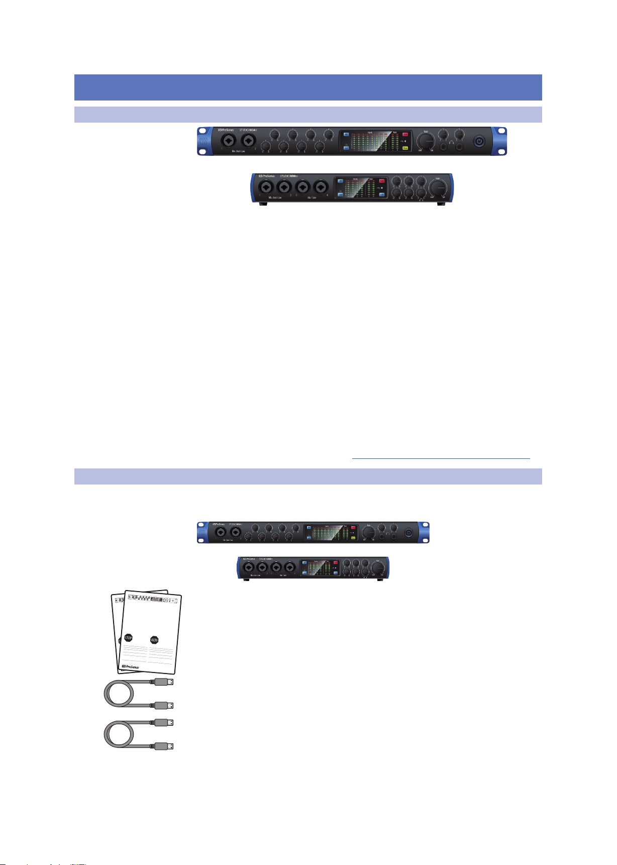
1.2 What is in the Box
You Studio-series package contains the following:
PreSonus Studio 1824c or Studio 1810c High-definition Audio Interface
Quick Start Guide
1M USB-C to C Cable
1M USB-C to A Cable
1
1 Overview
1.3 Companion PreSonus Products
External power supply
PreSonus Health Safety and Compliance Guide
Power User Tip: All companion software and drivers for your PreSonus Studio-series
interface are available for download from your My PreSonus user account. Simply visit
My.PreSonus.com and register your Studio-series interface to receive downloads and
licenses.
Studio Series 1810c and 1824c
Owner’s Manual
1.3 Companion PreSonus Products
Thanks for choosing PreSonus! As a solutions company, we believe the best way to
take care of our customers (that’s you) is to ensure that you have the best possible
experience from the beginning of your signal chain to the end. To achieve this goal,
we’ve prioritized seamless integration throughout every design phase of these
products from day one. The result is systems that communicate with each other
as intended—straight out of the box—without excessive configuration hassles.
We’re here for you. Find out more at www.presonus.com.
2

2 Hookup
2.1 Front Panel Connections and Controls
2 Hookup
2.1 Front Panel Connections and Controls
Microphone/Instruments/Line Inputs. Your Studio-series interface is equipped
with PreSonus XMAX microphone preamplifiers for use with all types of
microphones. The XMAX has a Class A input buffer, followed by a dual-servo gain
stage. This arrangement results in ultra-low noise and wide gain control, allowing
you to boost signals without increasing background noise.
Each microphone preamp is attached to the XLR input of the combo jack.
This convenient connector accepts either a 1/4-inch or XLR plug.
The ¼-inch TRS connectors on channels 1 and 2 can be switched
for either instrument- or line-level signals. The ¼-inch inputs on the
remaining combo connections are line-level inputs only.
Input Source. Channels 1 and 2 offer an input source selection button that lets you
switch between instrument- and line-level on the ¼-inch inputs for these two
channels. Press this button to disengage the instrument preamp when connecting
line-level devices. When the button is illuminated, the input will accept a line-level
source, such as a synthesizer or guitar amp modeler. Press this button to engage the
instrument preamp when connecting guitars or a passive bass.
Power User Tip: Active instruments are those that have an internal preamp or a line-level
output. Active instruments should be plugged into a line input rather than into an
instrument input. Plugging a line-level source into the instrument inputs not only risks
damage to these inputs but also results in a very loud and often distorted audio signal.
Please note: As with any audio input device, plugging in a microphone or an instrument,
or turning phantom power on or off, will create a momentary spike in the audio output of
your Studio-series interface. Because of this, we highly recommend that you turn down
the channel trim before changing connections or turning phantom power on or off. This
simple step will add years to the life of your audio equipment.
Input Gain Control. These knobs provide 80 dB of variable gain (-15 to +65 dB) on
the microphone and instrument inputs and 40 dB of variable gain (-20 to +20 dB) on
the line inputs.
Studio Series 1810c and 1824c
Owner’s Manual
48 Volt Phantom Power. Studio-series interfaces provide 48V phantom power for
the microphone inputs. Pressing the 48V button switches phantom power on and off
for all microphone inputs; the button will illuminate in blue when this function is
switched on.
WARNING: Phantom power is only required for condenser microphones and
can severely damage some dynamic mics, especially ribbon mics. Please
consult the documentation that came with your microphone before using phantom
power.
XLR connector wiring for phantom power:
Pin 1 = GND Pin 2 = +48V Pin 3 = +48V
3
2 Hookup
2.1 Front Panel Connections and Controls
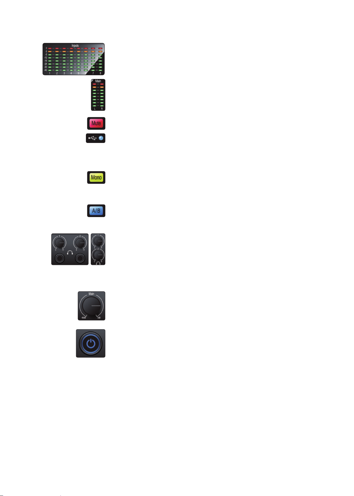
Input Meters. These LED meters show the input level of the analog inputs on your
Studio-series interface. The red Clip LED will illuminate when your input signal
reaches -0.5 dBFS. At this level, the signal will begin to overload the analog-to-digital
converters and exhibit signs of clipping. Use the gain controls to keep the signal
below this level.
Output Meters. These meters display the signal level received from the first two
driver returns (Main Left/Right). These meters have the same range as the input
meters (-50 dBFS to -0.5 dBFS) and are after the main output level control.
Mute. Press the Mute button to Mute the Main Output signal. The button will
illuminate Red when Mute is active.
Sync LED. This light indicates if your Studio-series interface is in sync with your
computer. When no sync is available, this light will flash red/blue. For Studio 1810c,
this light will also indicate if your external S/PDIF sync source is available. This light
will also flash if the sample rate you have set on your Studio-series device does not
match the sample rate you have set on your external clock source device.
Mono (Studio 1824c only). Press this button to sum the Main stereo output signal
to mono.
Power User Tip: Studio 1824c users can utilize the Mono feature to verify mono
compatibility and to check for phase cancellation in your stereo mixes.
Cue A/B (Studio 1810c only). This button allows you to switch the source that you
listen to through the Headphone 1 output. When the button is not illuminated,
playback streams 1 and 2 will be routed to the headphone output. Press the button
to route playback streams 3 and 4 to the Headphone 1 output instead.
Headphone Level. Your Studio-series interface provides two high-power
headphone outputs, each with its own level control. Studio 1824c users will find
both the headphone outputs and level controls on the front panel. Studio 1810c
users will find the level controls on the front panel and the outputs themselves on
the rear. On both units, Headphone 1 shares a stereo playback stream with the main
outputs and Headphone 2 shares its streams with outputs 3 and 4. For Studio 1810c
users, Headphone 1 can be switched between the two sets of streams via the A/B
button.
Main. The main knob controls the output level for the main left/right outputs on the
back of your Studio-series interface and has a range of -80 dB to 0 dB. This control
provides attenuation only.
Studio Series 1810c and 1824c
Owner’s Manual
Power Button and Sync light (Studio 1824c only). The lighted ring around the
power button of your Studio 1824c is a clock source indicator. It lets you know if your
unit is receiving word clock correctly.
• Blue. When this light is blue, your Studio 1824c is either the
master clock of your system or is receiving word clock from a
designate external source via the ADAT or S/PDIF input.
• Flashing Red and Blue. When this light flashes between blue
and red, your Studio 1824c is detecting a clock source.
• Purple. If this light is purple, your Studio 1824c cannot detect a clock source.
Power User Tip: Word clock is the timing signal with which digital devices sync frame
rates. Proper word clock sync prevents digital devices from having pops, clicks, and
distortion in the audio signal due to mismatched digital audio transmission. In general,
you will use your Studio 1824c as the master clock in your studio, and it provides highquality word clock for this purpose. However, in the event you would like to use another
device as the master clock, you can set the input source for clocking in UC Surface (see
Section 4.1 for details).
4
2 Hookup
2.2 Back Panel Connections
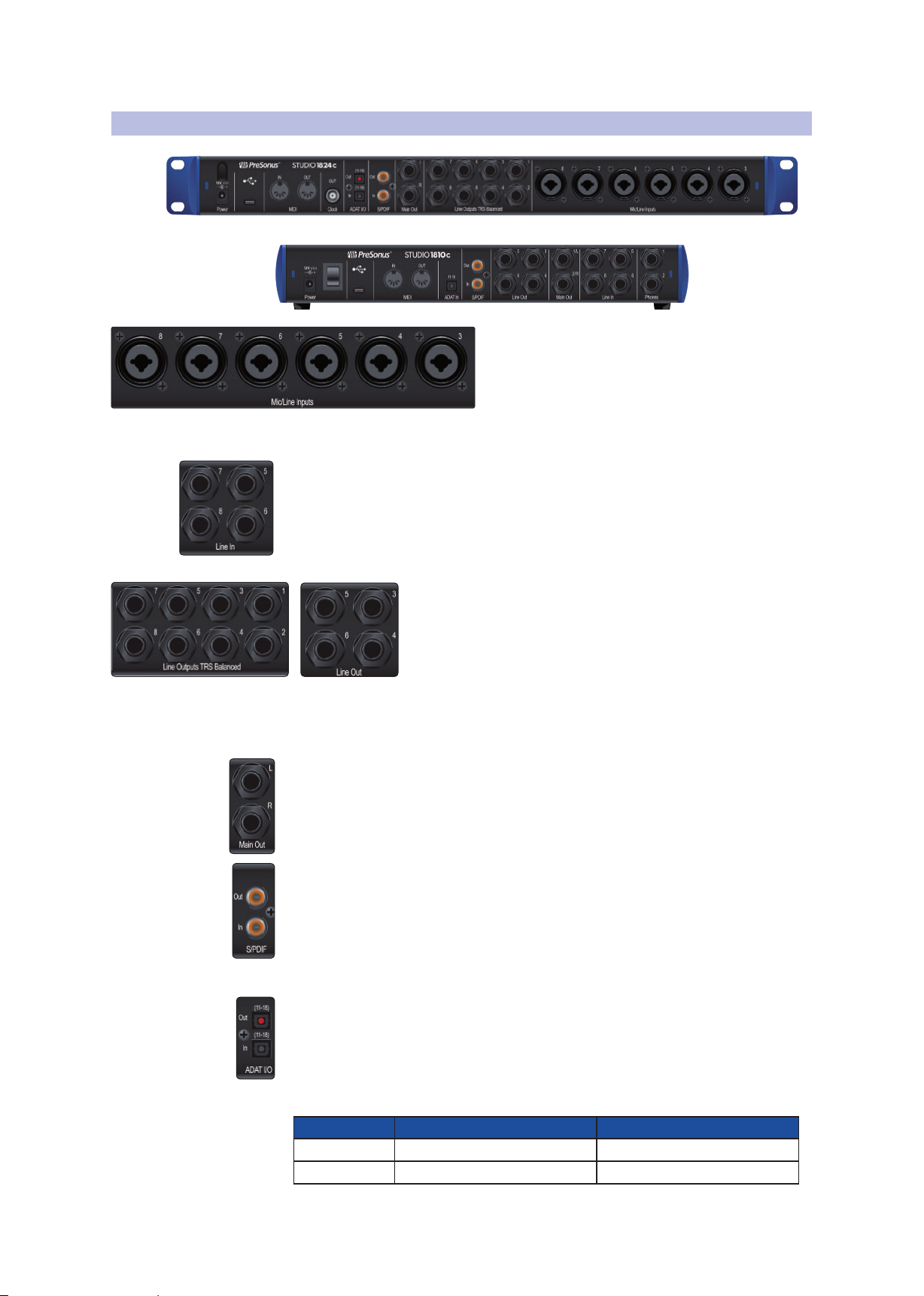
2.2 Back Panel Connections
Line Inputs (Studio 1810c only). Use these ¼-inch TRS inputs with line-level
devices. These inputs are scaled to accept line-level signals up to +18 dBFS.
Power User Tip: These inputs are direct-to-ADC. As such, no gain control available.
Typical examples of line-level connections are synthesizer outputs, signal processors, and
stand-alone mic preamps and channel strips. Use the output level control on your line
level device to adjust its level.
Studio 1810c. All other outputs have their own independent playback streams.
Power User Tip: Every line output is DC coupled to provide control voltage to external
analog equipment. This feature can be used with any plug-in that supports it.
Main Outputs. These are the main outputs for your Studio-series interface. The
output level of the Main Outputs is controlled by the Main Level control on the front
of the unit. Playback streams 1 and 2 are routed to the Main Outputs in addition to
Outputs 1 and 2 (Studio 1824c only) and Headphone 1.
Studio Series 1810c and 1824c
Owner’s Manual
Mic / Line Inputs (Studio 1824c only). The combo
connections on the rear panel of the Studio 1824c
can be used for both microphones and line-level
devices. Use the XLR connections for microphones
and D.I. boxes and the 1/4-inch TRS inputs for
line-level signals up to +18 dBFS. The trim control on
the front panel provides gain for both input types.
Line Outputs. These balanced ¼-inch TRS line outputs can be
used to route audio to external devices, such as headphone amps,
signal processors, and additional monitors. Studio 1824c: The first
two outputs share their playback streams with both the main
outputs and Headphone 1. Outputs 3 and 4 share their playback
streams with Headphone 2 for both the Studio 1824c and the
S/PDIF Input and Output. The S/PDIF connections allow two channels of audio to
be transmitted and received at rates up to 24 bit, 96 kHz. The S/PDIF I/O also allows
your Studio-series interface to send and receive word clock to external digital
devices.
Power User Tip: In UC Surface, you will need to set “S/PDIF” as the Clock Source and the
sample rate to correspond to the external device when using an external S/PDIF device as
your master clock. See Section 4.1 for details.
ADAT – S/MUX Input (Studio 1810c and Studio 1824c) and Output (Studio 1824c
only). These are the ADAT – Dual S/MUX connections for your external digital devices.
When recording or playing back at 44.1 or 48 kHz, each ADAT I/O will provide eight of
the sixteen available channels consecutively from left to right. When recording or
playing back at 88.2 or 96 kHz, each connection will provide four of the available eight
channels. These inputs and outputs do not function at 176.4 or 192 kHz:
ADAT Input (Studio 1810c and 1824c) ADAT Output (Studio 1824c only)
44.1 / 48 kHz Channels 11-18 Channels 11-18
88.2 / 96 kHz Channels 11-14 Channels 11-14
5

2 Hookup
2.2 Back Panel Connections
BNC Output (Studio 1824c only). This connection allows the Studio 1824c to
transmit word clock to other digital audio devices so that it can function as the
master clock for your studio environment (recommended).
MIDI Input and Output. MIDI stands for “Musical Instrument Digital Interface.” MIDI
inputs and outputs allow connection to, and communication with, external MIDI
equipment. One function of these ports is MIDI sequencing, but the MIDI protocol
can be used for much more than instruments and sequencing.
Power User Tip: MIDI is not audio but is frequently used to trigger or control an audio
source (such as a plug-in or synthesizer). It’s important to ensure that your MIDI data is
correctly sent and received by the appropriate hardware or software devices. If the devices
generate audio, you may also need to return the audio to a Studio-series interface input
channel. Please consult the User Manuals of your MIDI devices for help with MIDI setup
and usage.
USB-C Port. Use this port to connect your Studio 1810c or 1824c to your computer.
While the Studio 1810c and 1824c connect using USB-C, both are fully compatible
with USB 2.0 and 3.0 connections. Use the USB-C to A cable that came with your
interface if your computer has a USB-A connection rather than a USB-C connection.
Please note: Studio-series interfaces are backward compatible with USB 2.0 and USB 3.0
speed connections. USB 1.1 is not supported.
Power Connection. This is where you connect the Studio-series interface’s external
power supply.
Studio Series 1810c and 1824c
Owner’s Manual
Power Switch (Studio 1810c). This is the on / off switch for your Studio 1810c.
6

2 Hookup
DigiMax-series preamps
or other compatible hardware
Preamplificadores DigiMax
u otro hardware compatible
DigiMax-Verstärkern und
anderen kompatiblen Geräten
Préamplis de la série DigiMax
ou d’autres appareils compatibles
See Studio 1824c box for
computer requirements
Vea los requerimientos de
hardware en la caja de
Studio 1824c
Systemvoraussetzungen
siehe Studio 1824c
Packungsaufdruck
Voir la boîte de la Studio
1824c pour les
configurations
informatiques requises
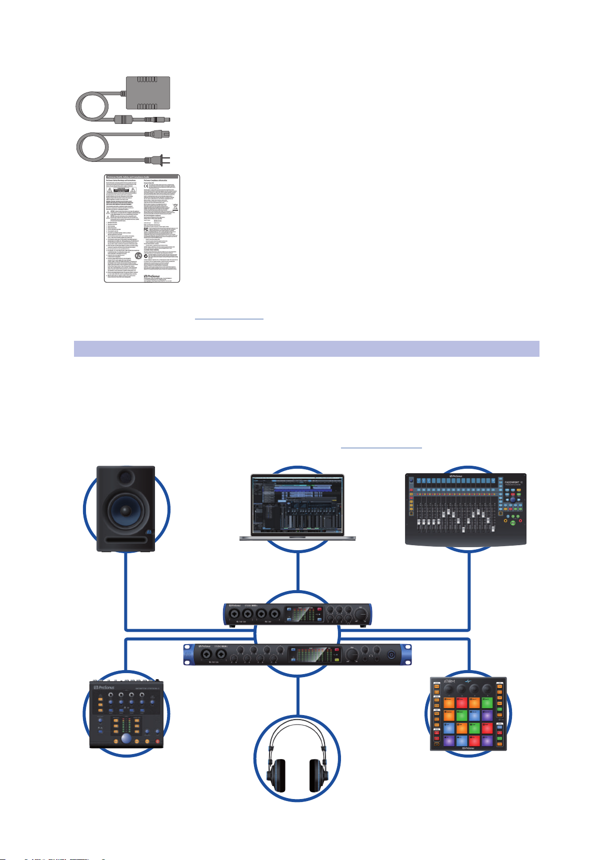
2.3 Connection Diagram
2.3 Connection Diagram
2.3.1 Studio 1824c
Studio Series 1810c and 1824c
Owner’s Manual
7

2 Hookup
DigiMax-series preamps
or other compatible hardware
Preamplificadores DigiMax
u otro hardware compatible
DigiMax-Verstärkern und
anderen kompatiblen Geräten
Préamplis de la série DigiMax
ou d’autres appareils compatibles
See Studio 1810c box for
computer requirements
Vea los requerimientos de
hardware en la caja de
Studio 1810c
Systemvoraussetzungen
siehe Studio 1810c
Packungsaufdruck
Voir la boîte de la Studio
1810c pour les
configurations
2.3 Connection Diagram
2.3.2 Studio 1810c
Studio Series 1810c and 1824c
Owner’s Manual
8

3 Connecting to a Computer
3.1 Installation for Windows
3 Connecting to a Computer
Your Studio-series interface is a powerful audio interface that is
loaded with professional audio tools and flexible monitoring controls.
Before connecting to a computer, please visit www.presonus.com
to verify the latest system requirements for your interface.
Note: The speed of your processor, amount of RAM, and capacity, size, and speed of your
hard drives will greatly affect the overall performance of your recording system. A faster
processor and more RAM can reduce signal latency (delay) and improve overall
performance.
All PreSonus interfaces utilize the Universal Control application for firmware
updates, device sync, and sample rate (Windows only). Both the Windows ASIO
driver and UC Surface are included in the Universal Control installer for macOS
and Windows. You can download the installer from your My PreSonus user
account. To begin, you must first visit My.PreSonus.com and create or log into
your user account and register your Studio-series. Once registered, all software
downloads will be available from within your My PreSonus user account.
3.1 Installation for Windows
Connect your Studio-series to an available USB-C or USB-A (2.0 or 3.0) port
and launch the installer. The Universal Control installer will take you through
each step of the installation process. This application will install the ASIO and
WDM drivers as well as UC Surface. Please read each message carefully.
It is recommended that you quit all applications before you start the installation.
Studio Series 1810c and 1824c
Owner’s Manual
3.2 Installation for macOS
Your Studio-series interfaces are class-compliant Core Audio devices in macOS.
No driver installation is necessary. However, to take full advantage of your
Studio 1824c and 1810c’s mixing capabilities, you must install Universal Control
to launch UC Surface. Universal Control also installs any necessary firmware
updates, so it is highly recommended that you install this application.
The Universal Control installer will take you through each step of
the installation process. Please read each message carefully so that
you do not connect your Studio-series interface too soon.
Power User Tip: When the installation is complete, you will find the Universal Control
application in your Applications folder. It is recommended that you place this in your
Dock for easy access.
3.3 Firmware Updates
Universal Control is designed to verify that your Studio-series
interface has the correct firmware version installed. You will be
prompted if your Studio-series interface needs its firmware updated.
Click on the Update Firmware button to begin the update.
WARNING: Do not power off or disconnect your Studio-series interface during
the firmware update. Once the firmware update is successfully completed, you
will be alerted and instructed to reboot your device.
9

3 Connecting to a Computer
Studio Series 1810c and 1824c
3.4 Using the Studio-series interfaces with Popular Audio Applications
3.4 Using the Studio-series interfaces with Popular Audio Applications
Complete setup instructions for Studio One Artist and a brief tutorial on
its features can be found in Section 5 of this manual. However, you can
use your Studio-series interfaces with any audio-recording application
that supports Core Audio or ASIO. Please consult the documentation that
came with your audio application for specific instructions on how to select
the Studio-series driver as the audio-device driver for your software.
Below are basic driver-setup instructions for a few popular audio applications.
Ableton Live
1. Launch Ableton Live
2. Go to Options | Preferences | Audio
3. Choose Driver Type: Asio | Audio Device: ASIO PreSonus Studio (1824c or
1810c)
4. Go to Input Config: Enable and select the desired Input channels.
5. Go to Output Config: Enable and select the desired Output channels.
Owner’s Manual
Apple Logic
Avid ProTools 10+
1. Launch Logic.
2. Go to Logic | Preferences | Audio.
3. Click on the Devices Tab.
4. Select PreSonus Studio (1824c or 1810c) from the device menu.
5. You will be asked if you’d like to relaunch Logic. Click try (re)launch.
6. Your Studio-series interface features custom I/O labels for faster workflow. To
enable these labels for use in Logic, go to Options | Audio | I/O Labels.
7. The second column in the pop-up window will be named Provided by Driver.
Activate each of these labels for your Studio-series interface. When you are done,
close this window.
1. Launch ProTools.
2. Go to Setup | Hardware and select Studio (1824c or 1810c) from the Peripherals
list. Click OK.
3. Go to Setup | Playback Engine and select Studio (1824c or 1810c) from the
menu at the top of the window. Click OK.
Cakewalk Sonar
1. Launch Sonar.
2. Go to Options | Audio... and click on the Advanced tab.
3. Change the Driver Mode to “ASIO.” (Note: Using WDM, rather than ASIO, for pro-
audio applications is not recommended.)
4. Click the “OK” button.
5. Restart Sonar.
10

3 Connecting to a Computer
3.4 Using the Studio-series interfaces with Popular Audio Applications
6. Go to Options | Audio... and click on the Drivers tab.
7. Highlight all input and output drivers beginning with “PreSonus Studio 1824c or
Studio 1810c.”
8. Go to Options | Audio... and click on the General tab.
9. Set the Playback Timing Master to “PreSonus Studio (1824c or 1810c)... DAW
Out 1.”
10. Set the Recording Timing Master to “PreSonus Studio (1824c or 1810c)...
Mic/Inst 1.”
Steinberg Cubase
1. Launch Cubase.
2. Go to Devices | Device Setup.
3. Select “VST Audio System” from the Devices column in the Device Setup.
4. Select PreSonus Studio (1824c or 1810c) from the ASIO Driver dropdown list.
5. Click “Switch” to begin using the Studio-series driver.
Studio Series 1810c and 1824c
Owner’s Manual
6. Once you have successfully changed the driver, go to Devices | VST Connections
to enable your input and output buses.
11
4 UC Surface Monitor Control Software
4.1 UC Surface Launch Window
4 UC Surface Monitor Control Software
Included in Universal Control for Studio-series interfaces is UC Surface is a powerful
monitor control software that provides everything you need to create high-quality
monitor mixes and more with your Studio-series interfaces. These same monitoring
functions are completely integrated into the Studio One mixer. UC Surface allows
users of other popular DAW applications to access these same functions. UC Surface
provides control of both channel and Mix output levels as well as solo and mute.
It is vital to remember that lowering the channel fader in UC Surface will not
lower the signal in your host application, so it is possible to clip the recording
without clipping the monitor mix. You must set the level for the recording
using the preamp controls on the face of your Studio-series interface.
A quick note on playback streams: The channels labeled “DAW” in UC Surface carry a
playback stream from your host application (DAW). Traditionally, if you wanted to route
a track in your DAW to a physical output on your interface, you assigned this output in
your host application. Because UC Surface provides much more flexible routing, you can
now route this same track to one output or every output, by itself or as part of a mix.
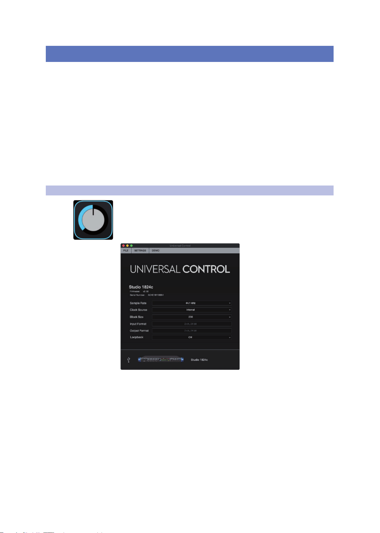
4.1 UC Surface Launch Window
Universal Control is a powerful hardware-management application for all PreSonus
interface products. It allows you to view any PreSonus interface product connected
to your computer or your computer’s network.
When Universal Control is launched, you will see the Launch window.
From this window, you can manage all the driver settings.
Studio Series 1810c and 1824c
Owner’s Manual
Sample Rate. Changes Sample Rate. You can set the sample rate to
44.1, 48, 88.2, 96, 176.4, or 192 kHz. A higher sample rate will increase
the fidelity of the recording, but will increase the file size and the
amount of system resources necessary to process the audio.
Clock Source. Sets the Digital Clock Source. From this menu,
you can set the Clock Source for your Studio-series interfaces:
Internal, External S/PDIF, or External ADAT (1824c only).
Block Size (Windows only). Sets the Buffer Size. From this menu, you can
set the Buffer Size for your Studio-series interface from 16 to 4096 samples.
Lowering the buffer size will reduce the overall latency. However, this will also
increase performance demands on your computer. In general, you will want
to set the buffer size as low as your system can safely support. If you begin to
hear pops, clicks or distortion in your audio path, try raising the buffer size.
Loopback (Windows only). The Studio 1810c/1824c ASIO driver
provides two loopback streams to record audio from one application
to another. See Section 4.1.1 for more information.
12

4 UC Surface Monitor Control Software
4.1 UC Surface Launch Window
File Menu. Manages devices connected to Universal Control.
• Show All Devices. Launches all control windows for all
supported devices connected to your computer.
• Close All Devices. Closes all open control windows.
• Sign Out. Signs out of your My PreSonus user account.
• Check for Updates... Connects to your My PreSonus user
account to check for updates for Universal Control.
• Transfers. Displays recent downloads from your my PreSonus user account.
• About Universal Control. Displays version and build date information.
• Quit. Quits the Universal Control application and all hardware control windows.
Studio Series 1810c and 1824c
Owner’s Manual
Settings Menu. Provide customization options to
personalize your Universal Control experience.
• Always on Top. Keeps the Universal Control Launch window on
top whether it is the currently active application or not.
• Run at Startup. Launches Universal Control
automatically when your computer boots.
• Preferences. Sets language and appearance options (see below).
• Rescan Network. Scans the network and local transport bus
(USB or FireWire) for all supported PreSonus products.
• Language. Sets the language (English, French, German,
Korean, Simplified Chinese, or Spanish).
4.1.1 Loopback Recording (Windows only)
The windows drivers for the Studio-series interfaces provide two virtual
streams that allow you to record the output of on audio application in
another application. Loopback can be useful in a variety of situations:
• Recording the audio from a video game or YouTube
video for a podcast or livestream.
13

4 UC Surface Monitor Control Software
4.1 UC Surface Launch Window
• Recording a vocal in real time over a karaoke track
played from a web browser or media player.
Power User Tip: Because the Studio-series interfaces are class compliant Core Audio
devices, these virtual streams are not available in macOS. However, there are several
third-party applications that provide this functionality in macOS.
From Universal Control, you can enable or disable Loopback and pick
the streams on which the loopback audio will be recorded.
When Loopback is enabled and “Merge Loopback with 1/2” is selected,
the audio from another application will be recorded with the audio source
connected to analog inputs 1 and 2 on your Studio-series interfaces.
Studio Series 1810c and 1824c
Owner’s Manual
Media Player
Web Browser
Etc.
When Loopback is enabled and “Dedicated Loopback Inputs” is selected, the audio
from another application will be recorded on the last pair of driver inputs (19/20).
Media Player
Web Browser
Etc.
Power User Tip: When using either option, you will need to select Outputs 1 and 2 in the
audio application you want to record. Make sure to select Outputs 3 and 4 in the audio
application in which your recording to avoid a feedback loop.
14

4 UC Surface Monitor Control Software
1
2
3
4
5
6
7
8
4.2 UC Surface Controls
Studio Series 1810c and 1824c
Owner’s Manual
4.2 UC Surface Controls
UC Surface allows you to create three (1810c) or four (1824c)
separate mixes of your input channels and every DAW return.
These low-latency mixes give you the ability to monitor your
inputs with minimal latency.
1. Main Mix Select. Use this button to view the Mix for
the Main Left/Right Outputs. This mix is also routed to
Outputs 1/2 and Headphone Output 1 simultaneously.
2. Mix Output Fader Position. Use this arrow to
toggle between placing your Mix Output Fader
to left or to the right of the Mix Controls.
3. Mute. Use this button to mute the currently selected Mix.
4. Mirror Main. When this button is enabled, the
currently selected mix will mirror the Main mix.
5. Mix Selection Buttons. Click to view the corresponding mix.
6. Mix Output Fader. This fader controls the overall
output level of the currently selected Mix.
7. Mix Meter. These meters display the pre-fader
output level of the currently selected Mix.
8. Copy Mix. Copying the current mix allows you to quickly set
up multiple mixes. Press the Copy Mix button and then click
on the desired Mix Select button followed by the Paste Mix
button to paste it.
15
4 UC Surface Monitor Control Software
1
2
3
4
5
6
7
8
9
10
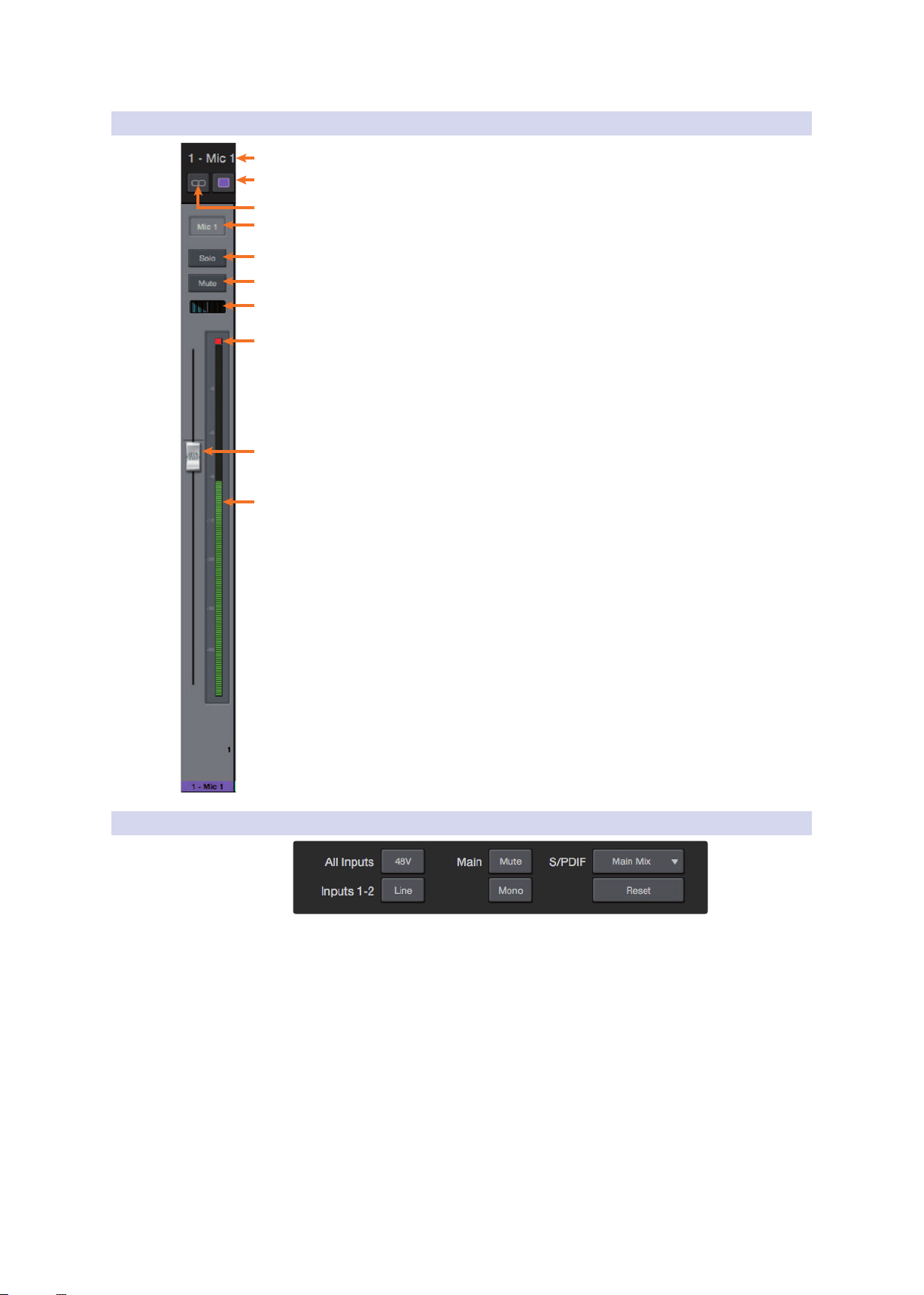
4.2 UC Surface Controls
4.2.1 Channel Controls
1. Selected Channel Name. Double-click on the name to customize it. This
field follows the currently selected channel.
2. Channel Color. UC Surface allows you color-code your channels, click here
to select a custom color. This field follows the currently selected channel.
3. Link. Channels can be stereo linked in odd-even pairs.
This control follows the currently selected channel.
4. Channel Select. Click to select a channel.
5. Solo Button. Turns Soloing On and Off.
6. Mute Button. Turns Muting On and Off.
7. Pan Controls. The pan control sets the channel’s relative position in the
left/right stereo mix. When a pair of channels is stereo linked, the pan
control sets the spread of the channels in the left/right stereo mix.
8. Input Clip. This indicates that your input has exceeded 0 dB FS. Click to clear.
9. Channel Fader. Controls the Overall Level of the Channel. By default,
all fader levels will be down on launch to avoid unwanted noise.
10. Level Meter. Displays the Pre-fader Level of Each Channel.
Studio Series 1810c and 1824c
Owner’s Manual
4.2.2 Device Controls
At the top of the UC Surface window are remote controls for the front panel
options on your Studio-series interface. Additionally, you will find the option
to select which monitor mix is being routed to your S/PDIF outputs. Clicking
the Reset button will restore the UC Surface mix settings to factory default.
16

4 UC Surface Monitor Control Software
4.3 The Settings Page
4.3 The Settings Page
The Settings page allows you to configure your Studio-series. To open the
configuration settings page, click on the Settings button in the upper right-hand
corner of the screen.
1. Show ADAT. This gives you the option to show your ADAT inputs in your UC
Surface Mixer. If you are not connecting external devices to your ADAT input,
you can turn this off to reduce the size of your monitor mixes and display just the
inputs you are using.
Studio Series 1810c and 1824c
Owner’s Manual
1
2
3
4
5
6
7
2. Peak Hold. Disables peak hold metering. By default, peak metering is active. To
change to peak hold metering, turn this control On.
3. Mixer Bypass. Bypasses UC Surface mixer and routing. While Mixer Bypass is
active, your Studio-series interface will function as a simple I/O device for your
DAW. When the mixer is bypassed, you must route audio to the desired output
using its dedicated playback stream both for system playback (if desired) and
DAW playback.
4. Color Scheme. This allows you to adjust the overall lightness or darkness of the
UC Surface Mixer.
5. Colorize Channels. You can select a custom color for just the channel name or
chose to color the entire channel strip.
6. Driver Settings. Displays the current driver settings for your Studio-series
interface. To change these settings, open the Launch window.
7. Version Info. Displays the current firmware and UC Surface version.
17

5 Studio One Artist Quick Start
5.1 Installation and Authorization
5 Studio One Artist Quick Start
All PreSonus professional recording products come with Studio One Artist recording
and production software. Whether you are about to record your first album or your
fiftieth, Studio One Artist provides you with all of the tools necessary to capture
and mix a great performance. PreSonus audio interfaces also have access to
advanced functions in Studio One’s exclusive Z-Mix feature for PreSonus interfaces.
Power User Tip: As a valued PreSonus customer, you are also eligible for a discount
upgrade to Studio One Professional. For more details on the Studio One upgrade
program for PreSonus customers, please visit http://studioone.presonus.com/.
Studio Series 1810c and 1824c
Owner’s Manual
5.1 Installation and Authorization
Once you have installed the drivers for your audio interface and connected it
to your computer, you can use the included PreSonus Studio One Artist musicproduction software to begin recording, mixing, and producing your music.
To install Studio One Artist, log into your My PreSonus account and register
your interface. Your Product Key for Studio One Artist will automatically be
registered to your My PreSonus account with your hardware registration.
Downloading and running the Studio One Installer
To install Studio One Artist, download the Studio One Artist installer from
your My PreSonus account onto the computer you will be using it.
• Windows Users: Launch the Studio One Artist installer
and follow the onscreen instructions.
• Mac Users: Drag the Studio One Artist application into the
Applications folder on your Macintosh hard drive.
18

5 Studio One Artist Quick Start
5.2 Setting Up Studio One
Authorizing Studio One
When Studio One is launched for the first time your computer, it will
communicate with your My PreSonus account and verify your registration.
To ensure a seamless authorization process, make sure to download your
installer onto the computer you will be using it and that your computer is
connected to the Internet when you launch the application for the first time.
Installing Bundled Content for Studio One Artist
Studio One Artist comes bundled with an array of demo and tutorial
material, instruments, loops, and samples. The Studio One Artist
bundle includes all that you need to begin producing music.
The first time you launch Studio One Artist, you will be prompted
to install its companion content. Select the content you wish to
add and click “Install.” The content will automatically begin to
download and install from your My PreSonus user account.
Studio Series 1810c and 1824c
Owner’s Manual
Power User Tip: You may be prompted to enter your My PreSonus user account
information. Clicking “Remember Credentials” will allow you to have immediate access to
any content you purchase from the PreSonus Marketplace.
5.2 Setting Up Studio One
Studio One Artist was designed to work with PreSonus interfaces and provides
unique interoperability and simplified set-up. When Studio One Artist is
launched, you will be greeted by to the Start page. On this page, you will
find document-management and device-configuration controls, as well as a
customizable artist profile, a news feed, and links to demos and tutorials from
PreSonus. If you have an Internet connection on your computer, these links will
be updated as new tutorials become available on the PreSonus Web site.
Complete information on all aspects of Studio One Artist is available in
the Reference Manual PDF located within Studio One. The information
in this tutorial covers only the basic aspects of Studio One Artist and is
intended to get you set up and recording as quickly as possible.
19

5 Studio One Artist Quick Start
5.2 Setting Up Studio One
5.2.1 Configuring Audio Devices
1. In the middle of the Start page, you will see the Setup area. Studio One Artist
automatically scans your system for all available drivers and select a driver. By
default, it will choose a PreSonus driver if one is available.
Power User Tip: If your device has zero-latency monitoring functionality from within
Studio One, you will see the Z-mix icon. If you do not see this icon, make sure that you
have launched Universal Control. PreSonus audio interfaces require their DSP mixing
control panels to be running in the background for Z-mix functionality.
2. If you do not see your device listed on the Start page when you launch Studio
One, click on the Configure Audio Devices link in the Setup area to open the
Options window.
Studio Series 1810c and 1824c
Owner’s Manual
In the Options window, click on the Audio Setup tab and
select your device driver from the pull-down.
5.2.2 Configuring MIDI Devices
From the External Devices window in Studio One Artist, you can configure
your MIDI keyboard controller, sound modules, and control surfaces. This
section will guide you through setting up your MIDI keyboard controller
and sound modules. Please consult the Reference Manual located within
Studio One for complete setup instructions for other MIDI devices.
If you are using a third-party MIDI interface or USB MIDI-controller
keyboard, you must install any required drivers for these devices before
beginning this section. Please consult the documentation that came
with your MIDI hardware for complete installation instructions.
If you do not have any MIDI devices, please skip to Section 5.3.
20

5 Studio One Artist Quick Start
5.2 Setting Up Studio One
Setting Up an External MIDI Keyboard Controller from the Start Page
A MIDI keyboard controller is a hardware device that is generally used for playing
and controlling other MIDI devices, virtual instruments, and software parameters.
In Studio One Artist, these devices are referred to as ‘Keyboards,’ and they must be
configured before they are available for use. In some cases, your MIDI keyboard
controller is also used as a tone generator. Studio One Artist views the controller
and tone-generation functions as two different devices; a MIDI keyboard controller
and a sound module. The MIDI controls (keyboard, knobs, faders, etc.) will be
set up as a Keyboard. The sound modules will be set up as an Instrument.
You can set up your external MIDI devices from the Setup area
on the Start page. Before setting up a new Song for recording,
take a moment to configure external devices.
Make sure you have connected the MIDI Out of your external MIDI controller to
a MIDI In on your PreSonus audio interface (if available) or other MIDI interface. If
you are using a USB MIDI controller, connect it to your computer and power it on.
1. Click on the Configure External Devices link in the Setup area on the Start page
to launch the External Devices window.
Studio Series 1810c and 1824c
Owner’s Manual
2. Click the Add Button. This will launch the Add Device window.
21

5 Studio One Artist Quick Start
5.2 Setting Up Studio One
3. From the menu on the left, select your MIDI controller from the list of
manufacturers and models. If you do not see your MIDI controller listed, select
New Keyboard. At this point, you can customize the name of your keyboard by
entering the manufacturer and device names.
Studio Series 1810c and 1824c
Owner’s Manual
4. You must specify which MIDI channels will be used to communicate with this
keyboard. For most purposes, you should select all MIDI channels. If you are
unsure of which MIDI channels to choose, select all 16.
5. Studio One allows you to filter out specific control functions your MIDI controller
provides. If you would like Studio One to ignore Aftertouch, Pitch Bend, Program
Change, or All CC messages, enable filtering for any or all of these messages.
6. In the ‘Receive From’ drop-down menu, select the MIDI-interface input from
which Studio One Artist will receive MIDI data (i.e., the MIDI port to which your
keyboard is connected).
Power User Tip: In the ‘Send To’ drop-down menu, select the MIDI interface output
from which your Studio One Artist will send MIDI data to your keyboard. If your
keyboard controller doesn’t need to receive MIDI data from Studio One, you can
leave this unselected.
7. If this is the only keyboard that you will use to control your external synthesizers
and virtual instruments, you should check the box next to Default Instrument
Input. This will automatically assign your keyboard to control all MIDI devices in
Studio One Artist.
8. Click OK
If you have a sound module that you’d like to connect, leave the External
Devices window open and proceed to the next part of this section.
If not, you can close the window and skip to the next section.
22

5 Studio One Artist Quick Start
5.2 Setting Up Studio One
Setting up an External MIDI Sound Module from the Start Page
MIDI instrument controllers (keyboards, MIDI guitars, etc.) send musical information
in the form of MIDI data to tone modules and virtual instruments, which respond
by generating sound, as instructed. Tone modules can be standalone sound devices
or can be integrated into a MIDI instrument, such as a keyboard synthesizer. Studio
One Artist refers to all tone generators as Instruments. Once you have set up your
MIDI keyboard controller, take a moment to configure your sound module.
Make sure you have connected the MIDI in of your external sound module to the
MIDI Out of your PreSonus audio interface (if available) or another MIDI interface.
1. In the External Devices window, click the Add button
Studio Series 1810c and 1824c
Owner’s Manual
2. Select your device the menu on the left. If your device is not listed, select New
Instrument. At this point you can customize the name of your keyboard by
entering the manufacturer and device names.
3. Specify which MIDI channels will be used to communicate with this sound
module. For most purposes, you should select all MIDI channels. If you are
unsure of which MIDI channels to select, we suggest you select all 16.
23

5 Studio One Artist Quick Start
5.3 Creating a New Song
4. In the Send To menu, select the MIDI interface output from which Studio One
Artist will send MIDI data to your sound module. Click OK and close the External
Devices window. You are now ready to start recording in Studio One Artist.
The rest of this Quick Start Guide will go over how to set
up a Song and will discuss some general workflow tips for
navigating through the Studio One Artist environment.
5.3 Creating a New Song
Now that you’ve configured your Audio and MIDI devices, let’s create
a new Song. We’ll start by setting up your default audio I/O.
1. From the Start page, select Create a New Song.
2. In the New Song window, name your Song and choose the directory in which
you’d like it saved. You’ll notice a list of templates on the left. These templates
provide quick set-ups for a variety of devices and recording situations. The
section will describe creating a Song from an empty session.
Studio Series 1810c and 1824c
Owner’s Manual
3. Select Empty Song from the Templates list. At this point, you should give your
Song a name and select your preferred sample rate and bit depth for recording
and playback. You can also set the length of your Song and the type of time
format you would like the timeline to follow (Notation Bars, Seconds, Samples, or
Frames). Click the OK button when you are finished.
Power User Tip: If you plan on importing loops into your song, make sure that the
Stretch Audio Files to Song Tempo option is selected. This will automatically import
loops at the correct BPM.
24

5 Studio One Artist Quick Start
5.3 Creating a New Song
5.3.1 Configuring Your I/O
1. Click on Song | Song Setup to set your sample rate, resolution, and configure
your Audio I/O.
2. Click on the Audio I/O Setup tab.
Studio Series 1810c and 1824c
Owner’s Manual
3. From the Inputs tab, you can enable any or all of the inputs on your PreSonus
audio interface you’d like available to you. We recommend that you create a
mono input for each of the inputs on your interface. If you plan on recording in
stereo, you should also create a few stereo inputs.
25
5 Studio One Artist Quick Start
5.3 Creating a New Song
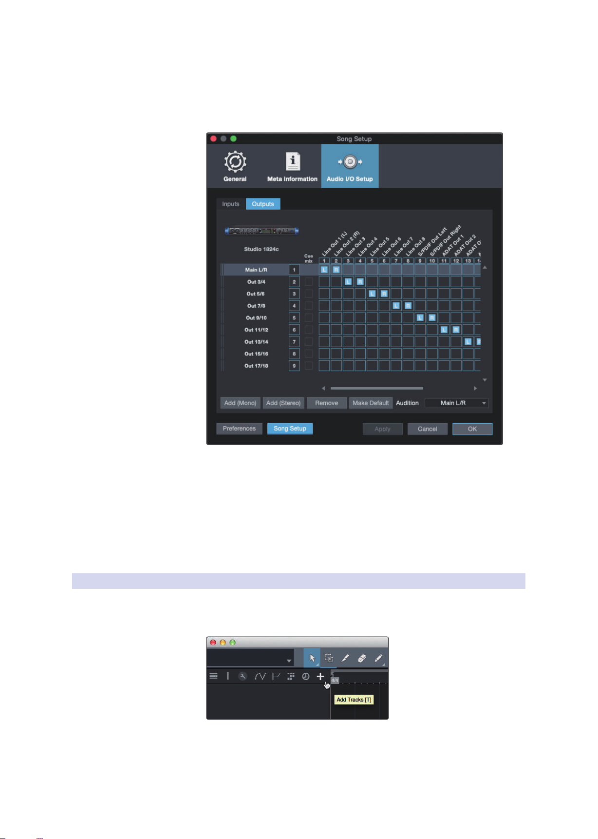
4. Click on the Outputs tabs to enable any or all of the outputs on your PreSonus
audio interface. In the lower right corner, you will see the Audition select menu.
This allows you to choose the output from which you will audition audio files
prior to importing them into Studio One Artist. In general, you will want this to
be the main output bus.
Studio Series 1810c and 1824c
Owner’s Manual
Power User Tip: If you would like this I/O configuration to be the same every time you
open Studio One, click the Make Default button.
Setting Up Z-Mix
PreSonus Studio-series interfaces provide zero-latency monitoring through
Studio One. To enable zero-latency monitoring, you must enable the outputs
for the mixes to be Cue Mix outputs. From the Outputs tab, click on the Cue Mix
box next to any output you’d like to use to send a zero-latency monitor mix.
For more information on Z-Mix, see Section 5.4.
5.3.2 Creating Audio & MIDI Tracks
1. In the upper left corner of the Arrange window, you will notice several buttons.
The button furthest to the right is the Add Tracks button. Click on this button to
open the Add Tracks window.
26

5 Studio One Artist Quick Start
Rec
Track
5.3 Creating a New Song
2. In the Add Tracks window, you can customize the track name and color, add a
preset rack of effects and set the physical source for the input and output of your
audio tracks from this window. Most importantly, can select the number and
type of tracks you’d like to create:
• Audio. Use this track type to record and playback audio files.
• Instrument. Use this track to record and playback MIDI data to
control external MIDI devices or Virtual Instrument plugins.
• Automation. This track type lets you create automated
parameter controls for your session.
• Folder. This track helps you to manage your session as
well as to quickly edit multiple tracks at once
Power User Tip: If you would like to add an audio track for each of the available
inputs, simply go to Track | Add Tracks for All Inputs.
Studio Series 1810c and 1824c
Owner’s Manual
Anatomy of an Audio Track
Custom
Track
Color
ST/Mono
Audio Input
Source Select
Note: MIDI Tracks are nearly identical to Audio Tracks. The Input Source list for MIDI tracks
lists available external MIDI devices as well as any Virtual Instruments that have been
added to the Song.
5.3.3 Recording an Audio Track
1. To begin recording, create an audio track from the Add Tracks window and set its
input to Input 1 on your PreSonus Audio Interface and connect a microphone to
the same input.
Mute
Solo
Arm
Monitor
Name
Meter
27

5 Studio One Artist Quick Start
5.3 Creating a New Song
2. Select Record Enable on the track. Turn up the Input 1 level on your audio
interface while speaking/singing into the microphone. You should see the input
meter in Studio One Artist react to the input. Adjust the gain so the input level is
near its maximum without clipping (distorting).
You are now ready to start recording. For complete instructions, please consult the
Studio One Reference manual located in Help | Studio One Reference Manual.
5.3.4 Adding Virtual Instruments and Plug-in Effects to Your Song
You can add plug-ins and instruments to your Song by dragging-and-dropping
them from the Browser. You can also drag an effect or group of effects from one
channel to another, drag in customized effects chains, and instantly load your
favorite virtual-instrument preset without ever scrolling through a menu.
Opening the Browser
In the lower right corner of the Arrange window are three buttons:
Studio Series 1810c and 1824c
Owner’s Manual
• The Edit button opens and closes the audio and MIDI editors.
• The Mix button opens and closes the Mixer window
• The Browse button opens the Browser window, which displays all of the
available virtual instruments, plug-in effects, audio files, and MIDI files,
as well as the pool of audio files loaded into the current session.
Drag-and-Drop Virtual Instruments
To add a virtual instrument to your session, open the Browser and click on
the Instrument button. Select the instrument or one of its patches from the
instrument browser and drag it into the Arrange view. Studio One Artist will
automatically create a new track and load the instrument as the input.
28

5 Studio One Artist Quick Start
5.4 Monitor Mixing with Z-Mix
Drag-and-Drop Effects
To add a plug-in effect to a track, click the Effects button in the Browser and
select the plug-in or one of its presets in the effects browser. Drag-and-drop
the selection over the track to which you would like to add the effect.
Drag-and-Drop Audio and MIDI Files
Audio and MIDI files can be quickly located, auditioned, and imported into
your Song by dragging them from the file browser into the Arrange view.
If you drag the file to an empty space, a new track will be created with
that file placed at the position to which you dragged it. If you drag the file
to an existing track, the file will be placed as a new part of the track.
Studio Series 1810c and 1824c
Owner’s Manual
5.4 Monitor Mixing with Z-Mix
PreSonus interface customers can set up zero-latency monitor mixes using
Studio One’s unique Z-Mix feature. This feature takes over the monitor mix
control software for the Studio-series interfaces and provides level and pan
control from within Studio One. Simply designate a pair or pairs of outputs
as a “Cue Mix,” and you’ll find the Z-Mix controls in your Studio One mixer.
As previously mentioned, Universal Control must be operating in the background
for Z-Mix functions to be available for your Studio-series interfaces.
zero-latency monitoring for live inputs. When the main output is designated as a Z-Mix, a
Zero Latency button will appear on any audio channel with an assigned audio input in
the Console, below the Mute, Solo, Record, and Monitor buttons.
You can create a cue mix and send it to any
output on your Studio-series interface. You
simply need to create an output bus and
enable Cue Mix.
Power User Tip: It is possible to designate the
main output in as a cue mix. This is helpful if you
often record yourself and require quick access to
29
5 Studio One Artist Quick Start
5.4 Monitor Mixing with Z-Mix
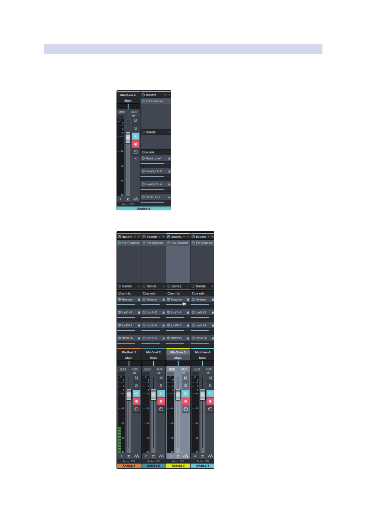
5.4.1 Z-Mix Functions
Once you have created a Cue Mix output, you will notice a special Send object
in the channels of the Console. This Send object is called a Z-Mix object.
In the Small Console view, Z-Mix objects appear in the
far left column of the extended channel.
Studio Series 1810c and 1824c
Owner’s Manual
In the Large Console view, Z-Mix objects appear below
the Send device rack on each channel.
30

5 Studio One Artist Quick Start
1 2 3 4
5.4 Monitor Mixing with Z-Mix
1. Activate Button. To completely remove any channel from a Z-Mix, simply
deactivate the Z-Mix object for that channel. In most instances, you will leave this
enabled.
2. Horizontal Level Fader. This is the channel’s Z-Mix Volume control. By default
this level will be identical to the level set on the channel’s fader. Once you
move the Z-Mix level fader, the volume of that channel in the Z-Mix will be
independent of the main mix or any other Cue Mix in the session.
Studio Series 1810c and 1824c
Owner’s Manual
To enable zero-latency hardware monitoring, click on the “Z” in the
output channel strip for the cue mix enabled output for which you’d like
to use zero-latency monitoring.
For more information on Cue Mix and Z-Mix monitoring, please consult
the Studio One Reference Manual in Studio One.
3. Pan Control. This sets the pan position for the channel in the Z-Mix outputs. Like
volume, panning is identical to the main mix by default.
4. Lock to Channel Button. By default, the Lock to Channel button is enabled,
and level and pan values are locked to the Channel level and pan controls for
the Main Mix. This means that each Z-Mix will be identical to the Main Mix in the
Console. Changing the level or panning in the Main Mix will change the level
or panning in the Z-Mix. However, changing the level or panning in the Z-Mix
object will unlock both settings, allowing independent control of level and
panning for each channel in each Z-Mix. Thus, the level and panning for channels
in a Z-Mix can be completely different from the related level and pan in the
Main Mix. At any time, you can lock the Z-Mix level and pan back to the channel
settings by clicking on the Lock to Channel button.
31

6 Technical Information
Studio Series 1810c and 1824c
6.1 Specifications
6 Technical Information
6.1 Specifications
General
Sample Rates 44.1, 48, 88.2, 96, 176.4, 192 kHz
Converter Resolution 24-bit
Converter Dynamic Range A/D 114 dB
Converter Dynamic Range D/A 114 dB
Microphone Inputs
Maximum Level +16 dBu, min gain
Gain Range 80 dB
Frequency Response 20 Hz - 20 kHz (unity gain)
Dynamic Range 110 dB (A-wtd, min gain)
THD + N 0.005% (1 kHz, 0dBu, unity gain)
EIN -128 dBu (A-wtd, 20 kHz BW, Rs=150Ω, max gain)
Input Impedance 1400Ω
Phantom Power 48V (>10 mA per channel)
Owner’s Manual
Line Inputs
Maximum Level +21 dBu (balanced, min gain)
Gain Range 40 dB
Frequency Response 20 Hz-20 kHz (unity gain)
Dynamic Range 112 dB (A-wtd, min gain)
THD + N 0.005% (1 kHz, +18 dBu, min gain)
Input Impedance 10 kΩ
Instrument Inputs
Maximum Level +15 dBu (unbalanced, min gain)
Gain Range 80 dB
Frequency Response 20 Hz - 20 kHz (min gain)
Dynamic Range 112 dB (A-wtd, min gain)
THD + N 0.020% (1 kHz, +10 dBu, min gain)
Input Impedance 1M Ω
Main Outputs
Type ¼” TRS female, DC Coupled
Maximum Level +18 dBu, balanced
Frequency Response 20Hz - 20kHz (unity gain)
Dynamic Range 108 dB (A-wtd, unity gain)
THD + N 0.004% (1 kHz, -1 dBFS, unity gain)
Line Outputs
Type ¼” TRS female, DC coupled
Maximum Level +18 dBu, balanced
Frequency Response 20 Hz - 20 kHz
Dynamic Range 108 dB (A-wtd, -60 dBFS)
THD + N 0.004% (1 kHz, -1 dBFS, unity gain)
32

6 Technical Information
Studio Series 1810c and 1824c
6.1 Specifications
Headphone Outputs
Maximum Power 150 mW/channel (60Ω load)
Frequency Response 20 Hz - 20 kHz (unity gain)
Dynamic Range 103 dB (A-weighted, 1 kHz, unity gain)
THD + N 0.250% (1 kHz, 150 mW, unity gain)
Impedance Working Range 32Ω to 600Ω
Physical
Height 1.75” (44 mm)
Width 1824c: 19” (483 mm), 1810c: 12.5” (317 mm)
Depth 5.5” (140 mm)
Weight 1824c: 4.8 lbs (2.2 kg), 1810c: 3.2 lbs. (1.45 kg)
Owner’s Manual
33

7 Warranty
7.1 Warranty Information
7 Warranty
7.1 Warranty Information
PreSonus’ warranty obligations for this hardware product
are limited to the terms set forth below:
How Consumer Law Relates To This Warranty:
THIS WARRANTY GIVES YOU SPECIFIC LEGAL RIGHTS, AND YOU MAY HAVE OTHER
RIGHTS THAT VARY FROM STATE TO STATE (OR BY COUNTRY OR PROVINCE). OTHER
THAN AS PERMITTED BY LAW, PRESONUS® DOES NOT EXCLUDE, LIMIT OR SUSPEND
OTHER RIGHTS YOU MAY HAVE, INCLUDING THOSE THAT MAY ARISE FROM THE
NONCONFORMITY OF A SALES CONTRACT. FOR A FULL UNDERSTANDING OF YOUR
RIGHTS YOU SHOULD CONSULT THE LAWS OF YOUR COUNTRY PROVINCE OR STATE.
PreSonus Products And EU Statutory Warranty:
When you purchase PreSonus products, European Union consumer
law provides statutory warranty rights in addition to the coverage
you receive from the PreSonus limited warranty. A summary of the EU
Statutory Warranty and the PreSonus Limited Warranty is below:
Studio Series 1810c and 1824c
Owner’s Manual
What This Warranty Covers:
PreSonus Audio Electronics, Inc., (“PreSonus”) warrants defects in material and
workmanship in PreSonus-branded products under normal use. This Limited
Warranty applies only to hardware products manufactured by or for PreSonus that
can be identified by the PreSonus trademark, trade name, or logo affixed to them.
Exclusions and Limitations:
This warranty does not cover the following:
1. Damage caused by accident, abuse, improper installation, failure to
2. Damage from improper grounding, faulty wiring (AC and signal),
EU Consumer Law PreSonus Limited Warranty
Repair or Replacement
Coverage For
Warranty Period
Cost of Coverage Provided at no additional cost Included at no additional cost
Who to contact to
make a claim
Defects present when customer
takes delivery
2 years (minimum) from
original date of purchase (unless
superseded by PreSonus)
The seller PreSonus technical support for your region
Defects arising after customer takes delivery
1 year from original date of purchase (unless superseded
by PreSonus)
follow instructions in the applicable owner’s manual or improper
operation, rental, product modification, alteration, or neglect.
faulty equipment, or connection to a voltage range outside
published specifications (see applicable owner’s manual).
3. Damage to drivers or diaphragm assemblies found to have burnt voice
coils from over/under driving or signal surge from another device.
4. Damage occurring during shipment or improper handling.
5. Damage caused by repair or service performed by
persons not authorized by PreSonus.
6. Products on which the serial number has been altered, defaced, or removed.
7. Products purchased from an unauthorized PreSonus dealer (products
that have transferable warranties are excluded from this provision,
provided the customer and the product are registered with PreSonus).
34

7 Warranty
7.1 Warranty Information
Who This Warranty Protects:
This Warranty protects only the original retail purchaser of the product
(products that have transferable warranties are excluded from this provision
provided the customer and the product are registered with PreSonus).
How Long This Warranty Lasts:
The Warranty begins on the original date of purchase from
the retail purchaser, and the duration is as follows:
1-Year Limited Warranty
Product Category Model Transferable
Recording Interfaces
Preamplifiers
StudioLive® Mixers
Monitoring & Controlling
Accessories Covers, Dolly, PRM1 mic, Sub Pole, breakout cables, power supplies, M10 Kit No
3-Years Limited Warranty
Product Category Model Transferable
Live Sound
Studio Series 1810c and 1824c
AudioBox® iOne, AudioBox iTwo, AudioBox Stereo, AudioBox Studio, AudioBox
USB, AudioBox VSL (1818, 44, 22), FireStudio™ Project, FireStudio Mobile,
FireStudio Mobile Studio, Studio 192, Studio 192 Mobile, Studio-series
(1824/1824c, 1810/1810c, 68/68c, 26/26c, 24/24c), Quantum, and Quantum 2
ADL600, ADL700, BlueTube DP V2, DigiMax D8, DigiMax DP88, Eureka, RC500,
Studio Channel, TubePre V2
Series III (32, 24, 16, 32R, 24R, and 16R) ,16.0.2, 16.4.2AI, 24.4.2AI, 32.4.2AI,
AR8, AR12, AR16, AR22, RM16AI, RM32AI
ATOM, Eris®, Central Station PLUS, FaderPort™, HP4, HP60, EarMix, Monitor
Station, Monitor Station V2, R-Series, Sceptre®, Temblor®
StudioLive AI 328, 312, 315, 18S, ULT10, ULT12, ULT15, ULT18, AIR10, AIR12,
AIR15, AIR15S, AIR18S
Owner’s Manual
No
No
No
No
Yes
What PreSonus Will Do:
PreSonus will repair or replace, at our sole and absolute option, products covered by this warranty
at no charge for labor or materials. If the product must be shipped to PreSonus for warranty service,
the customer must pay the initial shipping charges. PreSonus will pay the return shipping charges.
How to Get Warranty Service (USA):
1. You must have an active user account with PreSonus, and your hardware must be
2. Contact our Technical Support Department at (225) 216-7887 or log a
3. The return authorization number as well as shipping instructions shall
4. The product should be returned for service in the original product
on file with your account. If you do not have an account, please go to:
http://www.presonus.com/registration and complete the registration process.
support ticket at: http://support.presonus.com. TO AVOID THE POSSIBILITY
OF SENDING IN A PRODUCT THAT DOES NOT HAVE A PROBLEM, ALL SERVICE
REQUESTS SHALL BE CONFIRMED BY OUR TECH SUPPORT DEPARTMENT.
be provided after your service request is reviewed and confirmed.
packaging. Products may be shipped in a manufactured “flight”- or
“road”-style cases but PreSonus will NOT cover any shipping damage to
these cases. Products that are not shipped in the original product package
or a manufactured case may not receive a warranty repair, at PreSonus’s
sole discretion. Depending on the product model and the condition of
your original packaging, your product may not be returned to you in the
original packaging. The return shipping box may be a generic box that has
been fitted for that model tested if the original gift box is not available.
35

7 Warranty
7.1 Warranty Information
How to Get Warranty Service (outside of USA):
1. You must have an active user account with PreSonus and your hardware must
be on file with your account. If you do not have an account, please go to: http://
www.presonus.com/registration and complete the registration process.
2. Contact the Technical Support/Service Department for your region
at http://www.presonus.com/buy/international_distributors and
follow procedures provided by your PreSonus contact.
Limitation of Implied Warranties:
ANY IMPLIED WARRANTIES, INCLUDING WARRANTIES OF
MERCHANTABILITY AND FITNESS FOR A PARTICULAR PURPOSE, ARE
LIMITED IN DURATION TO THE LENGTH OF THIS WARRANTY.
Some states, countries, or provinces do not allow limitations on how long
an implied warranty lasts, so the above limitation may not apply to you.
Exclusion of Damages:
PRESONUS’S LIABILITY FOR ANY DEFECTIVE PRODUCT IS LIMITED TO THE
REPAIR OR REPLACEMENT OF THE PRODUCT, AT PRESONUS’S SOLE OPTION. IF
PRESONUS ELECTS TO REPLACE THE PRODUCT, THE REPLACEMENT MAY BE A
RECONDITIONED UNIT. IN NO EVENT WILL PRESONUS BE LIABLE FOR DAMAGES
BASED ON INCONVENIENCE, LOSS OF USE, LOST PROFITS, LOST SAVINGS, DAMAGE
TO ANY OTHER EQUIPMENT OR OTHER ITEMS AT THE SITE OF USE, AND, TO THE
EXTENT PERMITTED BY LAW, DAMAGES FOR PERSONAL INJURY, OR ANY OTHER
DAMAGES WHETHER INCIDENTAL, CONSEQUENTIAL OR OTHERWISE, EVEN IF
PRESONUS HAS BEEN ADVISED OF THE POSSIBILITY OF SUCH DAMAGES.
Some states, countries, or provinces do not allow limitations on how long
an implied warranty lasts, so the above limitation may not apply to you.
If you have any questions about this warranty or service received, please contact
PreSonus (USA) at +1 (225) 216-7887 or one of our authorized international
distributors at: http://www.presonus.com/buy/international_distributors.
Product features, design, and specifications are subject to change without notice.
Studio Series 1810c and 1824c
Owner’s Manual
36

Dinner is Served
Added bonus: PreSonus’ previously Top Secret recipe for…
Redfish Couvillion
Ingredients:
• ¼ C Vegetable oil
• ¼ C flour
• 1 onion diced
• 1 clove garlic minced
• 1 green pepper diced
• 3 celery stalks diced
• 1 14oz can diced tomatoes
• 1 bottle light beer
• 2 bay leaves
• 1 tsp thyme
• 2 lbs Redfish fillets
Cooking Instructions:
1. In a heavy saucepan or large skillet, heat oil on medium high and slowly add flour a tablespoon at a time to create a roux.
Continue cooking the roux until it begins to brown, creating a dark blond roux.
2. Add garlic, onions, green pepper, and celery to roux.
3. Sauté vegetables for 3-5 minutes until they start to soften.
4. Add tomatoes, bay leaves, thyme, and redfish. Cook for several minutes.
5. Slowly add beer and bring to a low boil.
6. Reduce heat and simmer uncovered for 30-45 minutes until redfish and vegetables are completely cooked, stirring occasionally. Break up redfish into bite size chunks and stir in. Add pepper or hot sauce to taste. Do not cover.
7. Serve over rice
Serves 6-8
While not one of Southeast Louisiana’s more famous dishes, Redfish Couvillion is a favorite way to serve our favorite Gulf fish.
Also known as Reds or Red Drum, Redfish is not only fun to catch, it’s also delicious!
© 2019 PreSonus Audio Electronics, Inc. All Rights Reserved. AudioBox, CoActual, DigiMax, Eris, FireStudio, Nimbit, PreSonus, QMix, Riff to Release, Sceptre, StudioLive, Active
Integration, and XMAX are trademarks or registered trademarks of PreSonus Audio Electronics, Inc. Capture, Impact, Mixverb Presence, RedLightDist, SampleOne, Studio One, and
Tricomp are trademarks or registered trademarks of PreSonus Software Ltd. Mac and Mac OS are registered trademarks of Apple, Inc., in the U.S. and other countries. Windows is a
registered trademark of Microsoft, Inc., in the U.S. and other countries. Other product names mentioned herein may be trademarks of their respective companies. All specifications
subject to change without notice...except the recipe, which is a classic.

Studio 1824c and 1810c
High-definition USB-C Audio Interfaces
Owner’s Manual
18011 Grand Bay Ct. • Baton Rouge,
®
Louisiana 70809 USA• 1-225-216-7887
www.presonus.com
Part# 70-12000123-A
 Loading...