

Instruction
IMPORTANT SAFETY INFORMATION. READ AND FOLLOW ALL SAFETY INSTRUCTIONS. Follow label information
and instructions concerning Wet or Damp Locations, installation near combustible materials, insulation, building materials,
n areas subject to combustible vapors or gases. Before wiring to power supply and
All servicing or relamping must be performed by
d to avoid potential electric shock or other potential hazard.
Product must be mounted in locations and at heights and in a manner consistent with its intended use, and in
quipment not recommended by
the manufacturer or installed contrary to instructions may cause an unsafe condition. Do not block light emanating from
, screens or
the like to come into contact with the product or to block light from the product, as this may cause an unsafe condition.
WARNING
– This product contains chemicals known to the State of California to cause cancer, birth defects and/or other
reproductive harm. Thoroughly wash your hands after installing, handling, cleaning, or otherwise touching this product.
NOTE: Maintain free airflow through the
Part No...........................................
and proper lamping. Do not install i
during servicing or relamping, turn off power at fuse or circuit breaker.
qualified service personnel. Product must be grounde
compliance with the National Electrical Code and local codes. The use of accessory e
product in whole or part, as this may cause an unsafe condition. Do not allow items such as drapes, curtains
INSTALLATION INSTRUCTIONS
MC10LED CYLINDER
93054545
www.prescolite.com
Sheet
CORD AND CABLE MOUNT
CAUTION: TO REDUCE THE RISK OF ELECTRICAL SHOCK, MAKE CERTAIN THAT THE
POWER SUPPLY IS TURNED OFF BEFORE INSTALLING OR SERVICING THIS PRODUCT!
fixture to avoid overheating.
CORD AND CABLE MOUNT
1. Unpack the MC10LED cylinder, the cable
mount parts bag, and the power cord from
the cylinder carton.
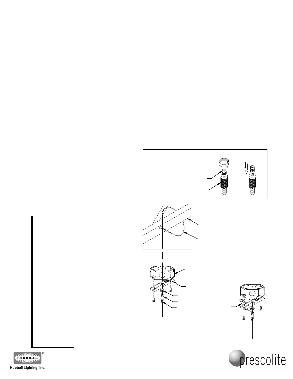
2. Loop the 20 foot galvanized cable around a
nearby structural member at the installation
location (Fig. 1). Assemble the crossbar and
threaded gripper as shown, using the hex
nut to lock the gripper in position. Loosen the
gripper cable lock nut and feed the cable
through the gripper as shown, and secure
the crossbar assembly to a properly installed
4" octagonal box (by others) designed to
support the weight of the fixture. NOTE: The
cable can be looped around the crossbar if
no structure is conveniently available, or if
there is no above-ceiling access (Fig. 2).
WARNING: Failure to connect the cable
end to the building structure or to a
properly installed junction box designed
to support the weight of the fixture may
allow the fixture to fall!
WARNING: Do not install cord and cable
hung fixtures in moving-air environments
such as near HVAC vents unless they are
laterally braced. Airflow may cause
continuous oscillation, which may cause
metal fatigue in the cabling system and
may cause the fixture to fall!
NOTE:
HOW THE GRIPPERS
AND LOCK NUTS WORK
LOCK NUT
GRIPPER
CEILING
Fig. 1
OCTAGONAL
BOX IN CEILING
CROSSBAR
HEX NUT
GRIPPER
LOCK NUT
UNLOCK
BUILDING
STRUCTURE
CABLE LOOP
AROUND
STRUCTURE
CABLE
LOOPED
AROUND
CROSSBAR
Fig. 2
PRESS
TO
RELEASE
Prescolite Toll Free Technical Support
1.888.PRS.4TEC
Hours: 8am - 5pm ET
701 Millennium Blvd• Greenville, SC 29607
With representatives offices in principal cities throughout North America.
Copyright , revision, All Rights Reserved - Printed in U.S.A.
2014 03/26/14

I
ns
t
r
uc
t
io
n
S
h
e
e
t
Part No...........................................
3. Lock the strain relief to the power cord with allowance for wiring connections, and thread the power cord
through the canopy wire hole (Fig. 3). Snap the cord assembly into the canopy. Make the ground connection
to the ground screw on the crossbar assembly and the Green-Striped ground conductor on the power cord.
Connect the line voltage to the Black-Striped conductor, the neutral to the White-Striped conductor. Make
any dimming control connections to the 2 extra conductors (Blue-Striped and Red-Striped, to be connected
in the fixture in the next steps – cap off these conductors if not used). Make all connections with properly
sized, UL listed connectors. Thread the 20 foot cable through the canopy center hole. Thread the 20 foot
cable through the barrel coupler, and slide it up to the canopy. Place the wiring and connections into the
junction box and push canopy up flush to the ceiling surface. Thread the barrel coupler onto the threaded
gripper body to retain the canopy. Tighten the cable gripper lock nut on the cable.
GROUND
SCREW
GRIPPER
LOCK NUT
CORD
STRAIN
RELIEF
POWER Cord
THREADED
GRIPPER
BODY
CANOPY
BARREL
COUPLER
93054545
www.prescolite.com
Prescolite Toll Free Technical Support
Fig. 3
4. Assemble the cable puck by dropping the ball-stop ends of the three 24 inch cables into the slots on the
puck bottom half (Fig. 4). Assemble the puck top half, making sure the cord opening in the top half lines up
with the one in the bottom half. Thread the ¼-20 gripper into the top center opening and tighten to hold the
puck assembly together.
1/4-20
GRIPPER
PUCK TOP
HALF
BALL-STOP
CORD
OPENING
ENDS
PUCK BOTTOM
HALF
24 INCH
CABLES
1.888.PRS.4TEC
Hours: 8am - 5pm ET
Fig. 4
701 Millennium Blvd• Greenville, SC 29607
With representatives offices in principal cities throughout North America.
Copyright , revision, All Rights Reserved - Printed in U.S.A.
2014 03/26/14

I
ns
t
r
uc
t
io
n
S
h
e
e
t
Part No...........................................
93054545
5. Loosen the lock nuts on the 3 swivel grippers on the top casting of the cylinder (Fig. 5). Insert the end of each of
the 24 inch cables from the puck assembly into a corresponding swivel gripper on the top casting. The cables
need to protrude through the grippers at least 1 inch (VIEW A). Tighten the lock nuts. (These cables can be
adjusted later in the installation.)
6. Loosen the lock nut on the ¼-20 gripper on the puck assembly and slide the puck assembly and fixture onto the
20 foot cable to the height the fixture is intended to hang. Loosen the locknuts on the three 24 inch cables and
adjust the fixture and the puck to level the fixture and set the cable lengths needed for the installation.
NOTE: The fixture weight will need to be lifted and supported so the grippers will release to allow adjustment of
the cables. After adjustment to the final position, tighten the lock nuts on all the grippers.
7. After the adjustment of the cable lengths is complete, slide the end of the 20 foot cable through one side of the
cable locking tube, loop the remaining length through the support tab hole, and then back through the other side
of the cable locking tube (VIEW B). Leave a couple of inches of slack in the 20 foot cable below the puck (this
cable should not be holding the fixture weight below the puck) and tighten the two screws on either side of the
cable locking tube. Trim the ends of the cables if needed using the proper cable cutting tool (such as a FELCO
C7). To prevent fraying of the cut cable ends, use a drop of superglue or solder the cable end.
CAUTION: Always leave at least 1 inch of cable beyond the body of the grippers.
20 FOOT
CABLE
www.prescolite.com
Prescolite Toll Free Technical Support
VIEW B
20 FOOT
CABLE
CABLE
LOCKING
TUBE
SUPPORT TAB
LOCK NUT
SWIVEL
GRIPPER
(1 OF 3)
VIEW A
1 INCH OF
CABLE
MINIMUM
LOCK NUT
1/4-20
GRIPPER
PUCK
ASSEMBLY
Fig. 5
SLACK IN
CABLE
BELOW
THE PUCK
1.888.PRS.4TEC
Hours: 8am - 5pm ET
701 Millennium Blvd• Greenville, SC 29607
With representatives offices in principal cities throughout North America.
Copyright , revision, All Rights Reserved - Printed in U.S.A.
2014 03/26/14
I
ns
t
r
uc
t
io
n
S
h
e
e
t
I
ns
t
r
uc
t
io
n
S
h
e
e
t
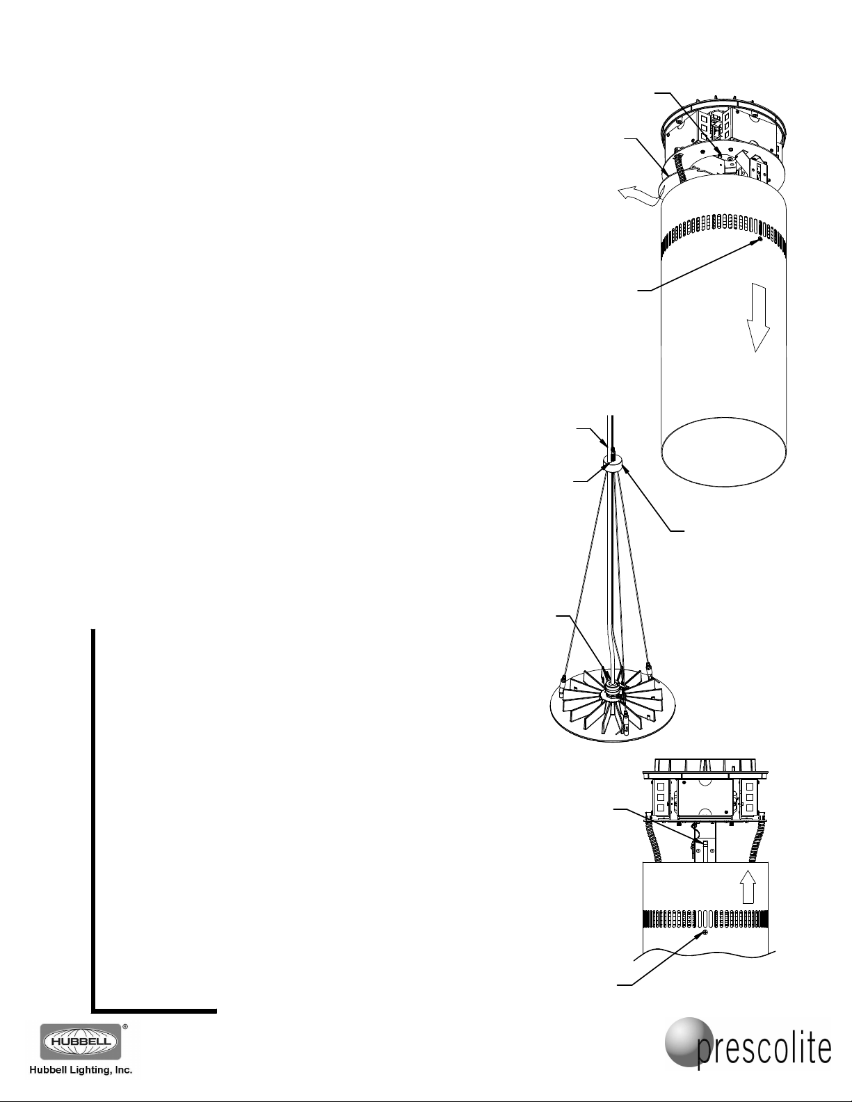
8. Carefully open the cylinder housing by loosening (do not
remove) the two Phillips screws on opposite sides of the
cylinder (near the vent slots) until the screws disengage from
the internal locking slots, and the cylinder housing is free to
slide down. Slide the outer cylinder housing open towards the
reflector (it should move about 7 inches from the top finned
casting) and tighten the two Phillips screws (Fig. 6).
9. Loosen the two thumbscrews holding the wiring compartment
cover closed, rotate the cover to free it, and carefully slide it
out of the way (there is a safety cable to hold it while the wiring
is being completed).
10. Feed the power cord through the hole in the puck assembly
and insert the end of the power cord through the cord grip and
into the cylinder wiring compartment (Fig. 7). Trim the power
cord to length, if needed. NOTE: If desired, tie the power cord
to the 20 foot cable with nylon cable ties every foot
trimming the power cord to length! Strip the jacket from the
power cord and strip the end of each conductor 3/8ths of an
inch. Make the electrical connections in the fixture wiring
compartment. The line voltage (Black-Striped) conductor
connects to the two-position connector with the Red thermal
protector wire. The neutral (White-Striped) conductor attaches
to the empty position on the connector with the White wires.
Connect the ground (Green-Striped) conductor to the twoposition connector with the Green wire. Use the two extra
power cord conductors (Blue-Striped and Red-Striped) to
connect to the dimming control wires, if provided. Make sure to
follow the same connection colors as used in Step 3. Cap off
these conductors if not used.
CAUTION: When making these connections, be careful
that no stray strands of wire stick out of the connectors
that might cause electrical shorts!
CAUTION: Do not allow the weight of the fixture to be
supported by the power cord! The weight of the fixture
should be supported by the cable system alone!
11. After the electrical connections are completed, replace the
wiring compartment cover and tighten the thumbscrews to
complete the wiring at the fixture.
12. Once again loosen (do not remove) the two Phillips screws on
opposite sides of the cylinder until the cylinder housing is free
to slide. Slide the MC10LED outer cylinder housing upwards
until it seats on the finned casting.
CAUTION: Do not pinch any wires between the cylinder
housing and any other parts of the fixture!
Be sure the cylinder housing is completely seated, and tighten
the two Phillips screws to lock the cylinder housing in place.
NOTE: If the cylinder housing does not fully seat when closing,
you may need to loosen the screws a little more to slide it
closed. This will allow the ends of the screws to pass the
locking slots at the very end of the slide travel (Fig. 8).
before
93054545
Part No...........................................
Part No...........................................
THUMBSCREW
(1 OF 2)
COMPARTMENT
POWER
CORD
POWER
CORD
HOLE
CORD
GRIP
WIRING
COVER
Fig. 6
PHILLIPS
SCREW
(1 OF 2)
LOCKING
SLOT
Fig. 8
SLIDE
HOUSING
OPEN
PUCK
Fig. 7
SLIDE
HOUSING
CLOSED
93054545
www.prescolite.com
www.prescolite.com
Prescolite Toll Free Technical Support
Prescolite Toll Free Technical Support
1.888.PRS.4TEC
1.888.PRS.4TEC
Hours: 8am - 5pm ET
Hours: 8am - 5pm ET
KEEP THESE INSTALLATION INSTRUCTIONS!
701 Millennium Blvd• Greenville, SC 29607
701 Millennium Blvd• Greenville, SC 29607
With representatives offices in principal cities throughout North America.
With representatives offices in principal cities throughout North America.
Copyright , revision, All Rights Reserved - Printed in U.S.A.
Copyright , revision, All Rights Reserved - Printed in U.S.A.
2014 03/26/14
2014 03/26/14
PHILLIPS
SCREW
(1 OF 2)
 Loading...