

Page 1
InstructionSheet
InstructionSheet
IMPORTANT SAFETY INFORMATION. READ AND FOLLOW ALL SAFETY INSTRUCTIONS. Follow label information
and instructions concerning Wet or Damp Locations, installation near combustible materials, insulation, building materials,
and proper lamping. Do not install in areas subject to combustible vapors or gases. Before wiring to power supply and
during servicing or relamping, turn off power at fuse or circuit breaker. All servicing or relamping must be performed by
qualified service personnel. Product must be grounded to avoid potential electric shock or other potential hazard.
Product must be mounted in locations and at heights and in a manner consistent with its intended use, and in
compliance with the National Electrical Code and local codes. The use of accessory equipment not recommended by
the manufacturer or installed contrary to instructions may cause an unsafe condition. Do not block light emanating from
product in whole or part, as this may cause an unsafe condition. Do not allow items such as drapes, curtains, screens or
the like to come into contact with the product or to block light from the product, as this may cause an unsafe condition.
INSTALLATION INSTRUCTIONS
WALL MOUNT
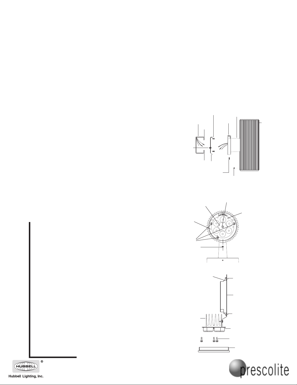
1. Detach mounting plate from cylinder bracket by loosening set screw (Fig.1).
Allen key is provided.
2. Secure mounting plate to outlet box with screws from outlet box (Fig.1).
3. Hang fixture on mounting plate by the mounting plate stud (Fig.1).
4. Make electrical connections. Splice black supply lead to black fixture lead and
white supply lead to white fixture lead. Secure fixture ground wire and supply
ground wire to ground screw (Fig. 1).
5. Secure the fixture in place by tightening the set screw (Fig. 1).
LED ARRAY REPLACEMENT
1. Using the Allen Key provided, loosen the end cap set screw.
Remove the lens assembly by rotating the end cap counter clockwise (Fig. 2).
2. Remove three LED array screws (Fig. 2). Keep screws for later assembly.
3. Pull the LED array assembly from the fixture (Fig. 3).
4. Disconnect power supply wires by disengaging the connector from the LED array
wire connector (Fig. 2). Note: Firmly hold the LED array and gently pull wire by
clasping the wire connector.
5. Remove the heat sink plate screw and heat sink plate to disengage the heat sink
from the LED array (Fig. 2).
6. Secure the replacement LED array to the heat sink by replacing the heat sink plate
and screw from step 5 (Fig. 2). Note: Make sure that the LED array wire connection
is oriented away from the wall bracket as illustrated in Fig. 2.
7. Connect the power supply to the LED array and slide LED array assembly into
fixture (Fig. 2).* Note: Hold the wire connector firmly when engaging with LED
array connector. Ensure proper pin orientation and secure firmly.
8. Secure the LED array assembly to the LED array mounting bracket with three
screws from step 2 (Fig. 2).
9. Re-install the lens assembly from step 1 by rotating the end cap clockwise.* To
ensure proper seal and to maintain UL listing, make sure the end cap is secured
tightly to the cylinder.
10. Tighten the end cap screw and apply Loctite 222 along the threads to seal it.
Part No. . . . . . . . . . . . . . . . . . . . . . . . . . . . . . . . .93001493
LD4UD SERIES
OUTLET BOX SCREWS
(PROVIDED BY OTHERS)
OUTLET BOX
(PROVIDED BY OTHERS)
GROUND SCREW
MOUNTING PLATE
FIG. 1
LED ARRAY
MOUNTING
BRACKET
LED ARRAY
SCREWS (3)
END CAP
SET SCREW
HEAT SINK
PLATE
MOUNTING
PLATE STUD
WALL BRACKET
SET SCREW
CYLINDER
BRACKET
END CAP
SET SCREW
HEAT SINK
PLATE SCREW
FIG. 2
LED ARRAY
WIRE CONNECTOR
www.prescolite.com • Prescolite TollFree Technical Support 1.888.PRS.4TEC • Hours: 8am - 5pm ET
CYLINDER
LED DRIVER REPLACEMENT
1. Using the Allen Key provided, loosen the end cap set screw.
2. Remove the lower lens assembly by rotating the end cap counter clockwise(Fig. 3).
3. Remove three LED array screws (Fig. 2). Keep screws for later assembly.
4. Pull the lower LED array assembly from the fixture (Fig. 3).
5. Disconnect LED power supply wires by disengaging the connector from the LED
array wire connector and the driver. Disconnect black and white power supply
leads from the driver (Fig. 2).
6. Remove driver screw #1 (keep for later assembly), and loosen driver screw #2 (Fig. 3).
7. Replace the driver, secure with screw #1, and tighten screw #2 (Fig. 3).
8. Reconnect the LED power supply leads to the driver and the LED array. Reconnect
black and white power supply leads to the driver.
9. Slide the lower LED array assembly back inside the fixture (Fig. 3).*
10. Secure lower LED array to the mounting bracket with three screws from step 2 (Fig.2).
11. Re-install the lens assembly from step 1 by rotating the end cap clockwise.* To ensure
proper seal and to maintain UL listing, make sure the end cap is secured tightly to the
cylinder.
12. Tighten the end cap screw and apply Loctite 222 along the threads to seal it.
* NOTE: Do not pinch LED array wires on end cap threads and internal mounting bracket.
101 Corporate Drive • Spartanburg, SC 29303
With representatives offices in principal cities throughout North America.
Copyright 2005, 06/05 revision, All Rights Reserved - Printed in U.S.A.
FIG. 3
HEAT SINK
POWER
SUPPLY
LEADS
LED DRIVER SCREW #1
LED DRIVER
LED DRIVER SCREW #2
LED ARRAY
LED ARRAY SCREWS
LENS ASSEMBLY
 Loading...