


WP2510

Operating Instructions and Parts Manual
25-inch Planer
Model WP2510
WMH TOOL GROUP
2420 Vantage Drive
Elgin, Illinois 60124 Part No. M-1791303
Ph.: 800-274-6848 Revision B3 2/07
www.wmhtoolgroup.com Copyright © WMH Tool Group

2
Warranty and Service
WMH Tool Group, Inc., warrants every product it sells. If one of our tools needs service or repair, one of our Authorized Service
Center located throughout the United States can give you quick service. In most cases, any of these WMH Tool Group
Authorized Service Centers can authorize warranty repair, assist you in obtaining parts, or perform routine maintenance and
major repair on your POWERMATIC
®
tools. For the name of an Authorized Service Center in your area call 1-800-274-6848.
MORE INFORMATION
WMH Tool Group is consistently adding new products to the line. For complete, up-to-date product information, check with your
local WMH Tool Group distributor, or visit powermatic.com.
WARRANTY
POWERMATIC products carry a limited warranty which varies in duration based upon the product.
WHAT IS COVERED?
This warranty covers any defects in workmanship or materials subject to the exceptions stated below. Cutting tools, abrasives
and other consumables are excluded from warranty coverage.
WHO IS COVERED?
This warranty covers only the initial purchaser of the product.
WHAT IS THE PERIOD OF COVERAGE?
The general POWERMATIC warranty lasts for the time period specified in the product literature of each product.
WHAT IS NOT COVERED?
The Five Year Warranty does not cover products used for commercial, industrial or educational purposes. Products with a Five
Year Warranty that are used for commercial, industrial or education purposes revert to a One Year Warranty. This warranty does
not cover defects due directly or indirectly to misuse, abuse, negligence or accidents, normal wear-and-tear, improper repair or
alterations, or lack of maintenance.
HOW TO GET SERVICE
The product or part must be returned for examination, postage prepaid, to a location designated by us. For the name of the
location nearest you, please call 1-800-274-6848.
You must provide proof of initial purchase date and an explanation of the complaint must accompany the merchandise. If our
inspection discloses a defect, we will repair or replace the product, or refund the purchase price, at our option.
We will return the repaired product or replacement at our expense unless it is determined by us that there is no defect, or that the
defect resulted from causes not within the scope of our warranty in which case we will, at your direction, dispose of or return the
product. In the event you choose to have the product returned, you will be responsible for the handling and shipping costs of the
return.
HOW STATE LAW APPLIES
This warranty gives you specific legal rights; you may also have other rights which vary from state to state.
LIMITATIONS ON THIS WARRANTY
WMH TOOL GROUP LIMITS ALL IMPLIED WARRANTIES TO THE PERIOD OF THE LIMITED WARRANTY FOR EACH
PRODUCT. EXCEPT AS STATED HEREIN, ANY IMPLIED WARRANTIES OR MERCHANTABILITY AND FITNESS ARE
EXCLUDED. SOME STATES DO NOT ALLOW LIMITATIONS ON HOW LONG THE IMPLIED WARRANTY LASTS, SO THE
ABOVE LIMITATION MAY NOT APPLY TO YOU.
WMH TOOL GROUP SHALL IN NO EVENT BE LIABLE FOR DEATH, INJURIES TO PERSONS OR PROPERTY, OR FOR
INCIDENTAL, CONTINGENT, SPECIAL, OR CONSEQUENTIAL DAMAGES ARISING FROM THE USE OF OUR PRODUCTS.
SOME STATES DO NOT ALLOW THE EXCLUSION OR LIMITATION OF INCIDENTAL OR CONSEQUENTIAL DAMAGES, SO
THE ABOVE LIMITATION OR EXCLUSION MAY NOT APPLY TO YOU.
WMH Tool Group sells through distributors only. The specifications in WMH catalogs are given as general information and are
not binding. Members of WMH Tool Group reserve the right to effect at any time, without prior notice, those alterations to parts,
fittings, and accessory equipment which they may deem necessary for any reason whatsoever.

3
Table of Contents
Warranty and Service .............................................................................................................................. 2
Table of Contents .................................................................................................................................... 3
Warning...................................................................................................................................................5
Introduction ............................................................................................................................................. 7
Specifications..........................................................................................................................................7
Unpacking ............................................................................................................................................... 8
Contents of the Shipping Container...................................................................................................... 8
Installation and Assembly ........................................................................................................................ 9
Dust Hood............................................................................................................................................9
Grounding Instructions........................................................................................................................... 10
230 Volt Operation ............................................................................................................................. 10
Converting from 230 Volt to 460 Volt .................................................................................................. 11
Test Run............................................................................................................................................ 11
Controller Set-Up ...............................................................................................................................11
Adjustments .......................................................................................................................................... 11
Depth of Cut....................................................................................................................................... 11
Feed Rate.......................................................................................................................................... 12
Belt Tension.......................................................................................................................................12
Opening Hood.................................................................................................................................... 12
Knife Inserts....................................................................................................................................... 12
The Planer’s Feed System..................................................................................................................... 13
Table Adjustments ............................................................................................................................. 16
Test Cutting and Troubleshooting .......................................................................................................... 17
Operation.............................................................................................................................................. 19
Maintenance.......................................................................................................................................... 19
Lubrication ......................................................................................................................................... 19
Controller (M15S) Operating Instructions............................................................................................... 20
1. Front Panel Overview..................................................................................................................... 20
2. Operation Modes............................................................................................................................21
3. Fast Program (10 sets)...................................................................................................................24
4. Select Counting direction................................................................................................................ 26
5. Select Positioning Mode................................................................................................................. 26
6. Set Software Limit (Hi/Lo End) ....................................................................................................... 27
7. Set Tolerances............................................................................................................................... 27
8. Set Low Speed Limit ...................................................................................................................... 28
9. Set Linear Correction .....................................................................................................................29
10. Enter Parameter Setttings Mode...................................................................................................29
11. Check Software Version ............................................................................................................... 30
12. Load Datum Values...................................................................................................................... 30
13. IN/MM Conversion........................................................................................................................32
14. Set Device Resolution.................................................................................................................. 32
15. Calibration.................................................................................................................................... 33
16. M15S Troubleshooting .................................................................................................................33
17. M15S Specifications..................................................................................................................... 35
Troubleshooting: Planer Operating Problems......................................................................................... 36
Troubleshooting: Mechanical and Electrical Problems............................................................................ 37
Replacement Parts................................................................................................................................ 38
Column Assembly.............................................................................................................................. 39
Parts List: Column Assembly.............................................................................................................. 40
Gearbox Assembly............................................................................................................................. 42
Parts List: Gearbox Assembly ............................................................................................................ 43
Parts List: Cutterhead Assembly ........................................................................................................ 44
Table Assembly ................................................................................................................................. 46
Parts List: Table Assembly................................................................................................................. 47
Base Assembly.................................................................................................................................. 48
Parts List: Base Assembly..................................................................................................................49
Parts List: Top Cover Assembly ......................................................................................................... 52
Parts List: Top Cover Assembly ......................................................................................................... 52

4
Parts List: Electrical Box Assembly.....................................................................................................53
Electrical Connections – 230Volt............................................................................................................ 54
Electrical Connections – 460Volt............................................................................................................ 55

5
Warning
1. Read and understand the entire owners manual before attempting assembly or operation.
2. Read and understand the warnings posted on the machine and in this manual. Failure to comply with
all of these warnings may cause serious injury.
3. Replace the warning labels if they become obscured or removed.
4. This planer is designed and intended for use by properly trained and experienced personnel only. If
you are not familiar with the proper and safe operation of a planer, do not use until proper training and
knowledge have been obtained.
5. Do not use this planer for other than its intended use. If used for other purposes, WMH Tool Group
disclaims any real or implied warranty and holds itself harmless from any injury that may result from
that use.
6. Always wear approved safety glasses/face shields while using this planer. Everyday eyeglasses only
have impact resistant lenses; they are not safety glasses.
7. Before operating this planer, remove tie, rings, watches and other jewelry, and roll sleeves up past
the elbows. Remove all loose clothing and confine long hair. Non-slip footwear or anti-skid floor strips
are recommended. Do not wear gloves.
8. Wear ear protectors (plugs or muffs) during extended periods of operation.
9. Some dust created by power sanding, sawing, grinding, drilling and other construction activities
contain chemicals known to cause cancer, birth defects or other reproductive harm. Some examples
of these chemicals are:
• Lead from lead based paint.
• Crystalline silica from bricks, cement and other masonry products.
• Arsenic and chromium from chemically treated lumber.
Your risk of exposure varies, depending on how often you do this type of work. To reduce your
exposure to these chemicals, work in a well-ventilated area and work with approved safety
equipment, such as face or dust masks that are specifically designed to filter out microscopic
particles.
10. Do not operate this machine while tired or under the influence of drugs, alcohol or any medication.
11. Make certain the machine is properly grounded.
12. With the exception of feed rate adjustment, make all machine adjustments or maintenance with the
machine disconnected from the power source. A machine under repair should be RED TAGGED to
show it should not be used until the maintenance is complete.
13. Remove adjusting keys and wrenches. Form a habit of checking to see that keys and adjusting
wrenches are removed from the machine before turning it on.
14. Keep safety guards in place at all times when the machine is in use. If removed for maintenance
purposes, use extreme caution and replace the guards immediately.
15. Check damaged parts. Before further use of the machine, a guard or other part that is damaged
should be carefully checked to determine that it will operate properly and perform its intended
function. Check for alignment of moving parts, binding of moving parts, breakage of parts, mounting
and any other conditions that may affect its operation. A guard or other part that is damaged should
be properly repaired or replaced.
16. Provide for adequate space surrounding work area and non-glare, overhead lighting.
17. Keep the floor around the machine clean and free of scrap material, oil and grease.
18. Keep visitors a safe distance from the work area. Keep children away.

6
blahblahblah
19. Make your workshop child proof with padlocks, master switches or by removing starter keys.
20. Give your work undivided attention. Looking around, carrying on a conversation and “horse-play” are
careless acts that can result in serious injury.
21. Maintain a balanced stance at all times so that you do not fall or lean against moving parts. Do not
overreach or use excessive force to perform any machine operation. Stand to the side out of line with
the table and make sure no one else is standing in line with the table.
22. Use the right tool at the correct speed and feed rate. Do not force a tool or attachment to do a job for
which it was not designed. The right tool will do the job better and safer.
23. Maintain tools with care. Keep knife inserts sharp and clean for the best and safest performance.
Follow instructions for lubricating machine and changing accessories. Use recommended
accessories; improper accessories may be hazardous.
24. Do not attempt to plane boards shorter than 10” in length without butting a board of equal thickness
behind it to help it through the planer. Be sure the last board of a butted sequence is 12” or longer.
25. Do not feed stacked boards through a planer; a kickback may occur causing severe or fatal injury.
26. Do not plane boards with loose knots or with nails or any foreign material on its surface. Twisted,
warped, or wind-in stock should first be jointed on one surface before attempting to plane a parallel
surface on the planer. Serious stock flaws cannot be removed by use of a planer alone.
27. Disconnect machine from power source before cleaning. Use a brush or compressed air to remove
chips or debris — do not use your hands.
28. Do not stand on the machine. Serious injury could occur if the machine tips over.
29. Never leave the machine running unattended. Turn the power off and do not leave the machine until it
comes to a complete stop.
30. Remove loose items and unnecessary work pieces from the area before starting the machine.
Familiarize yourself with the following safety notices used in this manual:
This means that if precautions are not heeded, it may result in minor injury and/or
possible machine damage.
This means that if precautions are not heeded, it may result in serious injury or possibly
even death.
- - SAVE THESE INSTRUCTIONS - -

7
Introduction
This manual is provided by WMH Tool Group covering the safe operation and maintenance procedures
for a Powermatic Model WP2510 Planer. This manual contains instructions on installation, safety
precautions, general operating procedures, maintenance instructions and parts breakdown. This machine
has been designed and constructed to provide years of trouble free operation if used in accordance with
instructions set forth in this manual. If there are any questions or comments, please contact either your
local supplier or WMH Tool Group. WMH Tool Group can also be reached at our web site:
www.wmhtoolgroup.com.
Specifications
Model Number..............................................................................................................................WP2510
Stock Number...............................................................................................................................1791303
Main Drive Motor ................................................................TEFC, 15HP, 3Ph, 230/460V (pre-wired 230V)
Table Hoist Motor ......................................................................................................... TEFC, 1/2HP, 3Ph
Maximum Cutting Width (in.).................................................................................................................. 25
Maximum Cutting Thickness (in.)............................................................................................................. 9
Full Width Cutting Depth (in.)................................................................................................................ 1/8
Maximum Cutting Depth (in.) ................................................................................................................ 1/4
Minimum Planing Length (in.) ................................................................................................................ 10
Number of Knives, Helical Head ................................................................ 168 (four-sided carbide inserts)
Segmented Infeed Roll Diameter (in.) ......................................................................................................3
Steel Outfeed Roll Diameter (in.) ....................................................................................................... 2-1/2
Cutterhead Speed (RPM) ................................................................................................................. 5,000
Cutterhead Diameter (in.) .................................................................................................................. 3-3/8
Feed Rate (FPM)......................................................................................................................... 30-25-20
Table Size (L x W)(in.)............................................................................................................32-3/16 x 26
Dust Port Diameter (in.)........................................................................................................................... 5
Shipping Weight (lbs.)....................................................................................................................... 1,760
Net Weight (lbs.)............................................................................................................................... 1,585
Overall Dimensions (L x W x H)(in.) .................................................................................. 42 x 53-1/2 x 60
The above specifications were current at the time this manual was published, but because of our policy of
continuous improvement, WMH Tool Group reserves the right to change specifications at any time and
without prior notice, without incurring obligations.
8
Unpacking
Open shipping container and any smaller boxes
and check for shipping damage. Report any
damage immediately to your distributor and
shipping agent. Do not discard any shipping
material until the planer is installed and running
properly.
Compare the contents of your container with the
following parts list to make sure all parts are
intact. Missing parts, if any, should be reported
to your distributor. Read the instruction manual
thoroughly for assembly, maintenance and
safety instructions.
NOTE: To remove the box from atop the planer
table, loosen the table lock handle, push in the
elevating handwheel (see Figure 3) and rotate
the handwheel to lower the table.
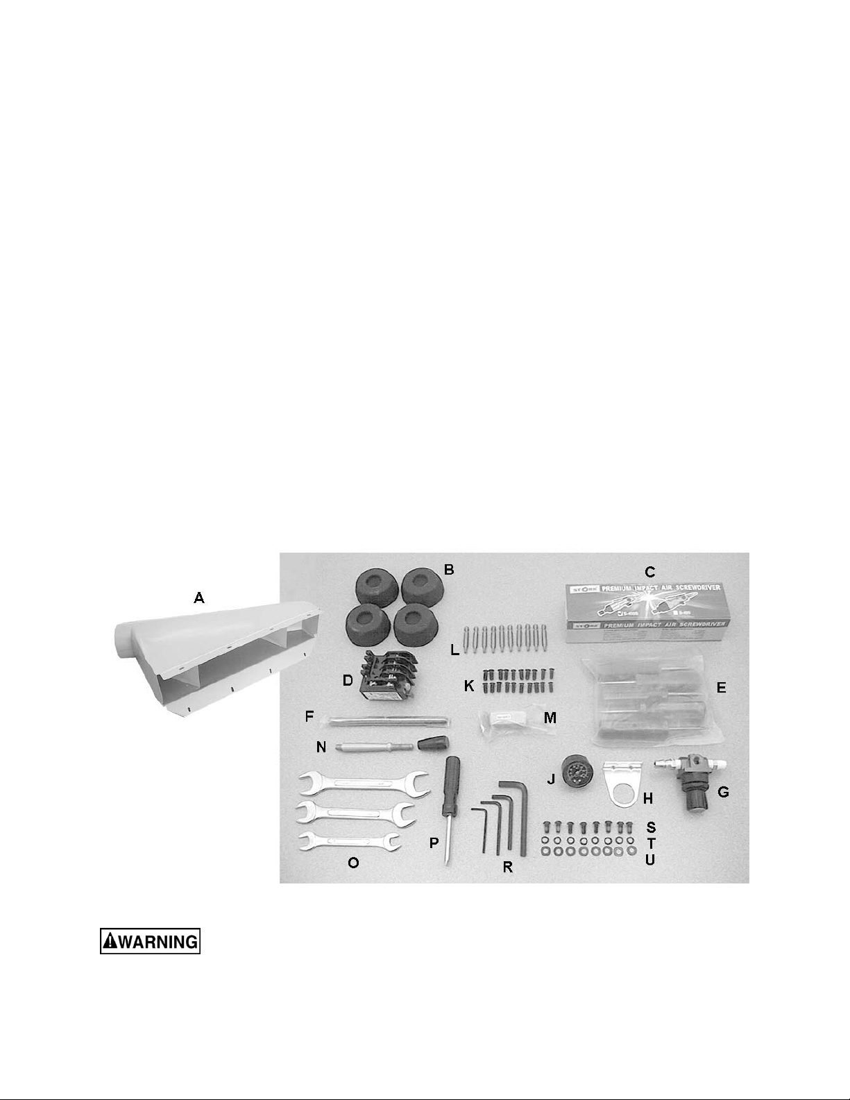
Contents of the Shipping Container
1 Planer
1 Dust Hood – (A)
4 Foot Pads – (B)
1 Air Impact Screwdriver – (C)
1 RA-30E 460V Overload Relay – (D)
5 Star Point Screwdrivers – (E)
1 Breaker Bar – (F)
1 Air Valve – (G)
1 Air Valve Mounting Bracket – (H)
1 Air Valve Pressure Gauge – (J)
20 Flat Head Spline Socket Screws,
M6x14 – (K)
10 Spline Bits, T-20 – (L)
10 Replacement Knife Inserts – (M)
1 Handle with Knob – (N)
3 Open End Wrenches, 17-19, 22-24, and 12-
14 mm – (O)
1 Reversible Screwdriver – (P)
4 Hex Wrenches, 3, 4, 5, and 8mm – (R)
8 Button Head Socket Screws, M6x12 – (S)
8 Lock Washers, M6 – (T)
8 Flat Washers, M6 – (U)
1 Operating Instructions and Parts Manual
1 Warranty Card
Read and understand the entire contents of this manual before attempting set-up
or operation! Failure to comply may cause serious injury.
9
Installation and Assembly
Tools Required for Installation:
Forklift or hoist, with lifting straps
4mm hex wrench (provided)
22mm combination wrench (provided)
Remove any straps or boards holding the planer
to the pallet. Place straps under the four lifting
hooks at front and back to raise the planer off
the pallet and move it to location.
Make sure the straps will not
damage buttons or levers on the front of the
planer.
The planer should be installed on a solid
foundation, preferably a concrete floor. The
machine area should be clean, dry, well
ventilated, and well lit. Since planers can create
noise problems, the site selection should be one
which minimizes reverberant sound from walls,
ceilings and other equipment. Electricals should
be installed so that they are protected from
damage and exposure. Be sure to properly
ground the machine.
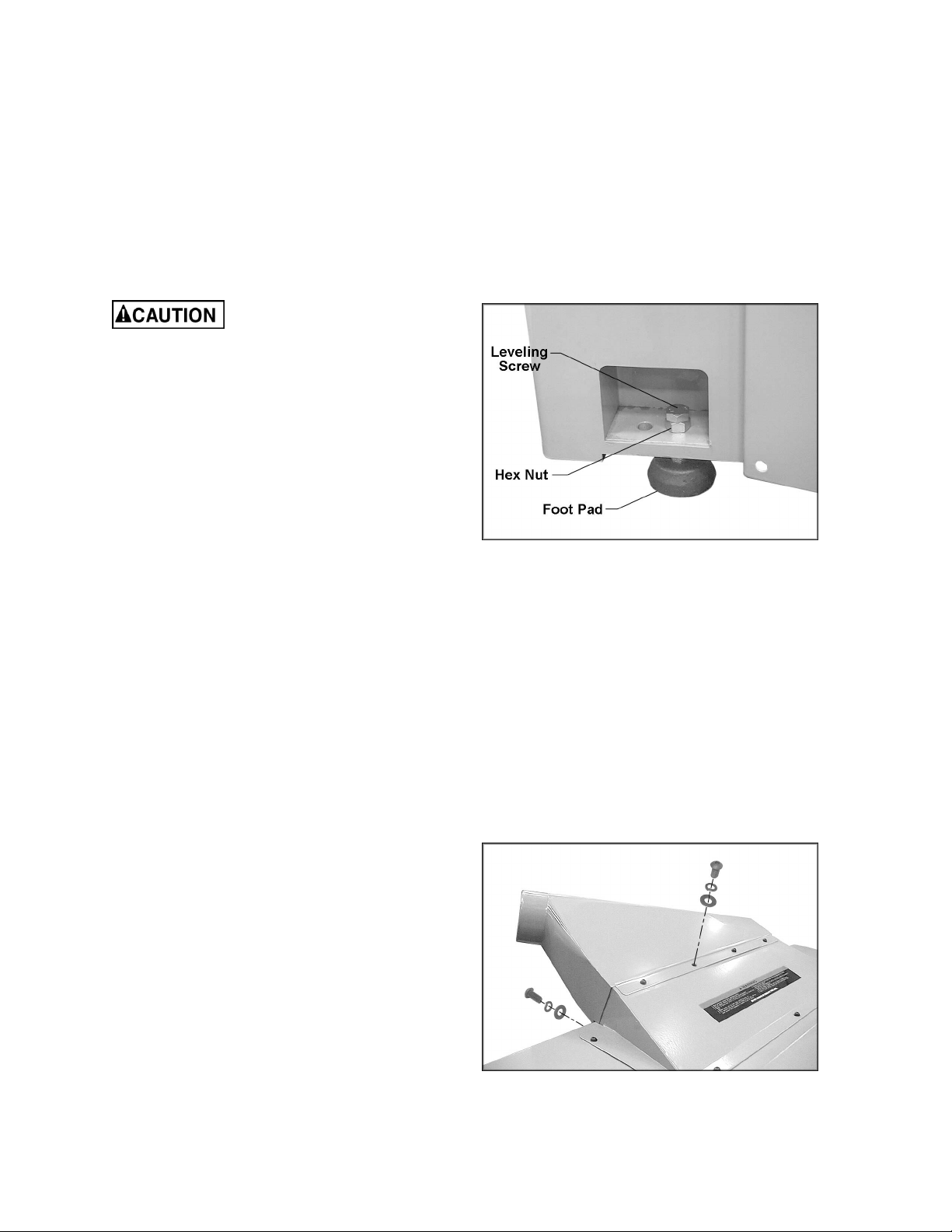
Lower the leveling screws, and place the four
foot pads beneath the leveling screws. See
Figure 1. Lower the machine slowly onto the foot
pads. The screws can be turned as necessary
until the planer table is level. Tighten the hex
nuts against the base to secure the screw
settings.
Exposed metal parts have been coated with a
rust preventative. This should be removed with a
soft cloth moistened with kerosene or a good
commercial cleaner/degreaser. Do not use an
abrasive pad, and do not get solvents near
plastic parts or painted areas.
Dust Hood
Use a 4mm hex wrench to mount the dust hood
to the planer with eight M6 x 12 button head
socket screws, eight M6 lock washers and eight
M6 flat washers, as shown in Figure 2.
It is strongly recommended that a dust collection
system be used with this machine. It should be
of sufficient volume for this size planer. If a dust
collector is not used, the user is cautioned
against the health hazard and the limitations in
the OSHA regulation for employee or student
exposure to dust particles.
Figure 1
Figure 2

10
Grounding Instructions
Electrical connections must
be made by a qualified electrician in
compliance with all relevant codes. This
machine must be properly grounded to help
prevent electrical shock and possible fatal
injury.
This machine must be grounded. In the event of
a malfunction or breakdown, grounding provides
a path of least resistance for electric current to
reduce the risk of electric shock.
Improper connection of the equipment-
grounding conductor can result in a risk of
electric shock. The conductor with insulation
having an outer surface that is green with or
without yellow stripes, is the equipment-
grounding conductor. If repair or replacement of
the electric cord or plug is necessary, do not
connect the equipment-grounding conductor to a
live terminal.
Check with a qualified electrician or service
personnel if the grounding instructions are not
completely understood, or if in doubt as to
whether the tool is properly grounded.
Repair or replace a damaged or worn cord
immediately.
Make sure the voltage of your power supply
matches the specifications on the motor plate of
the Planer. The machine should be connected to
a dedicated circuit.
The use of an extension cord is not
recommended for the WP2510 Planer.
230 Volt Operation
The Planer is factory wired for 230 volt, but can
be converted to 460 volt if so desired (see
“Converting From 230 Volt to 460 Volt”). You
may either install a plug or “hard-wire” the
Planer directly to a control panel.
If you are connecting a plug, use a proper
UL/CSA listed 3-pole, 4-wire grounding plug
suitable for 230 volt operation.
If the Planer is to be hard-wired to a panel,
make sure a disconnect is available for the
operator.
During hard-wiring of the Planer, make sure the
fuses have been removed or the breakers have
been tripped in the circuit to which the Planer
will be connected. Place a warning placard on
the fuse holder or circuit breaker to prevent it
being turned on while the machine is being
wired.

11
Converting from 230 Volt to 460 Volt
Consult the diagrams on pages 54 and 55 for
specific information on the following changes.
1. Disconnect machine from power source.
2. Change the lead connections to the main
motor and to the table hoist motor.
3. Replace the RA-30 (230V) overload relay
with the provided RA-30E (460V) overload
relay.
4. Switch the “R” wire on the transformer from
the 230V to the 460V terminal.
5. If using a plug, install a proper UL/CSA
listed plug suitable for 460V operation.
Test Run
After wiring has been completed, confirm that
the wires have been connected properly:
1. Connect machine to power source and
press the “Main Motor” button for just an
instant, then press the Stop button.
2. The cutterhead should rotate clockwise as
viewed from the handwheel side of the
machine. If cutterhead rotation is incorrect,
disconnect machine from power source
and switch any two of the three wires at
"R,S,T" (see “Electrical Connections”, pages
54 and 55).
3. Re-connect machine to power source.
Controller Set-Up
To program settings in the Controller for table
movement, refer to the section beginnning on
page 20.
Adjustments
Depth of Cut
Depth of cut is adjusted by raising or lowering
the table using the elevating handwheel or the
push buttons for rough positioning; or the
keypad on the Controller. The Controller is used
for very precise positioning and for remembering
your settings (for more information on the
Controller see the section beginning on page
20).
To move the table with the elevating handwheel
(Figure 3), push the handwheel in to engage the
sprocket on the table elevating mechanism. One
revolution of the handwheel equals 1/32”
change in table height. Use the scale or digital
readout to determine distance from the
cutterhead.
Figure 3

12
Feed Rate
The planer is equipped with selectable feed rate
rollers that feed stock at 20, 25 or 30 feet per
minute. To adjust speed, rotate the lever shown
in Figure 4.
IMPORTANT: Change feed rate only while
the machine is running.
Belt Tension
1. Disconnect machine from power source.
2. Remove the lower rear panel and use the
four hex nuts on the motor mount to adjust
belt tension. See Figure 5. Adjust motor
plate up or down until correct belt tension is
achieved. To lower the motor plate, loosen
lower nuts and tighten upper nuts. To raise
the motor plate, do the opposite.
3. Correct tension is obtained when there is
approximately 1/4” deflection in the center
span of the belt using light finger pressure.
4. Re-tighten hex nuts and install lower rear
panel.
Opening Hood
To open the hood for access to the cutterhead,
remove the two shoulder screws (Figure 4).
NOTE: The planer has a limit switch which
prevents operation while the hood is open.
Knife Inserts
Knife inserts are extremely
sharp. Use caution when working with or
around the cutterhead.
The knife inserts are four-sided. When dull,
simply remove each insert, rotate it, and re-
install it. To maintain quality of cut, replace or
rotate all inserts at the same time.
If one or more knife inserts develops a nick,
rotate only those inserts that are affected.
An air-operated screwdriver has been provided
to speed up the setting of inserts and to ensure
the proper torque to seat the inserts securely in
the cutterhead. Assemble the regulator valve
(Figure 6) and connect it to the air supply and to
the air-operated screwdriver. The valve can be
mounted to a surface using screws (not
provided) through the slots in the bracket. Pull
up the knob and rotate to adjust pressure; push
the knob down to secure the setting.
1. Disconnect machine from power source.
Figure 4
Figure 5
Figure 6
13
2. Remove the top left side panel so that you
can rotate the cutterhead using the belts.
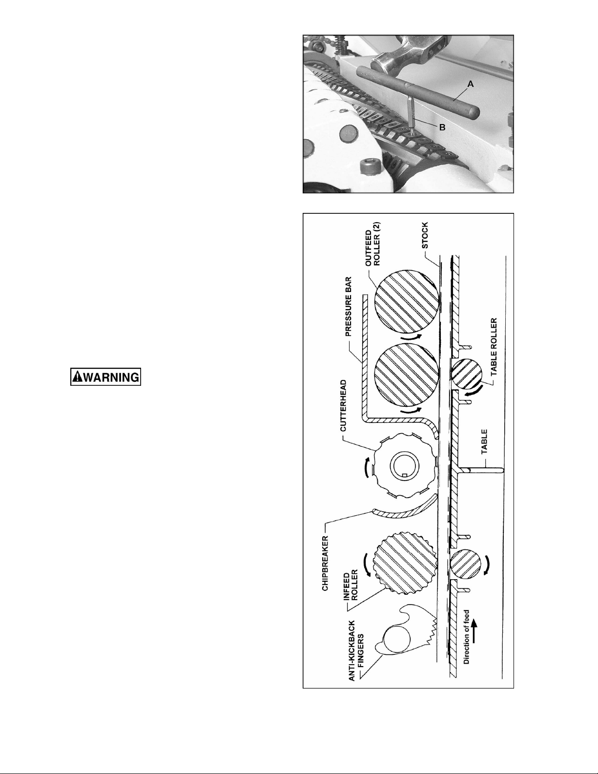
3. To remove a knife insert, unscrew the flat
head screw with a spline screwdriver, or the
air-operated screwdriver using one of the
provided T-20 spline bits. If the screw will
not budge, place the hole of the breaker rod
(A, Figure 7) over a spline bit (B, Figure 7)
and lightly tap the breaker rod
counterclockwise with a hammer to break
loose the screw.
4. Remove the flat head screw, and remove
the knife insert.
5. Carefully wipe clean the insert seat on the
cutterhead and install the new knife insert
(or rotate the present one).
6. The knife insert should be “pre-set” and then
given a final tightening. Install the flat head
screw, and turn the screw until the knife
insert is snug. To pre-set, you may use one
of the spline screwdrivers provided, or use
the air-operated screwdriver set at 45 psi.
7. When finished pre-setting the knife insert,
set the air operated screwdriver to 85 psi,
and fully tighten the screw.
8. Repeat for all knife inserts.
Make sure all knife inserts
are secure in the cutterhead. Failure to
comply may allow knife inserts to loosen and
be flung from the machine during operation.
The Planer’s Feed System
(Figure 8)
1. Anti-Kickback Fingers
2. Infeed Roller
3. Chipbreaker
4. Cutterhead
5. Pressure Bar
6. Outfeed Rollers
Anti-Kickback Fingers
Anti-kickback fingers help prevent stock from
being thrown from the machine. These fingers
operate by gravity and should be inspected for
pitch or gum buildup before each day’s use. The
fingers must operate freely and move
independently for correct operation.
Infeed Roller
The function of the infeed roller is to feed the
material into the machine. It is a corrugated,
sectional roller with approximately 1/4”
independent movement of each section to
accomodate multiple board surfacing.
Figure 7
Figure 8
14
To provide proper drive, the infeed roller should
be set so that the bottom of its arc is 1/16” below
the arc of the cutterhead knife inserts. The
infeed roller is under spring tension and this
tension must be sufficient to feed the stock
uniformly through the planer without slipping but
should not be so tight that it causes damage to
the boards. The tension should be equal at both
ends of the roller.
To adjust the infeed roller:
1. Disconnect machine from power source.
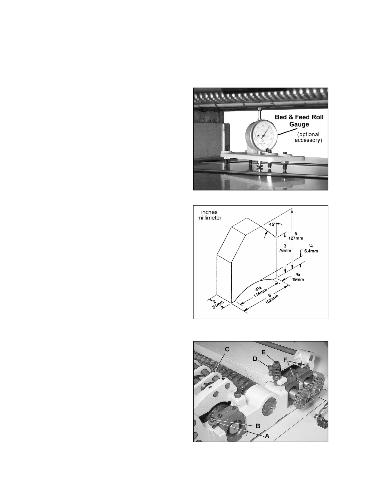
2. Place a dial gauge under a knife insert in
the cutterhead. (Figure 9 shows a Bed and
Feed Roll Gauge – accessory #2230002 –
which can be purchased from your dealer. )
If a dial gauge is not available, use a
finished block of wood with notches cut out
for the table rollers, in conjunction with a
feeler gauge. See Figure 10 for an example
of a wood block you can make and use as a
gauge.
3. Raise the table with the handwheel until the
gauge contacts a knife insert at the apex of
its curve. Zero the gauge at that position.
4. Move the gauge to the extreme left side of
the infeed roller and check the
measurement. It should be 1/16” below the
knife measurement.
5. If it is not 1/16”, correct by loosening the hex
nut (A, Figure 11) and turning the
adjustment screw (B, Figure 11) with a hex
wrench.
6. Move the gauge to the extreme opposite
end of the infeed roller and check. Make
necessary adjustments. Tighten hex nuts
(A, Figure 11) when finished.
IMPORTANT: The setting on both sides of the
infeed roller must be the same to avoid skewing
of the material as it is fed through the machine.
Chipbreaker
The chipbreaker (C, Figure 11) is a
sectionalized type made of spring-loaded
sections mounted on a bar, which complements
the sectional infeed roller. The functions of the
chipbreaker are to break chips into small pieces,
help avoid splintering of the wood, help avoid
board bounce on thinner boards, to direct the
flow of chips out of the machine, and to permit
multiple board surfacing.
The chipbreaker has been factory set at 1/32”
below the cutting arc of the knives, and has
been spring-tensioned properly.
Figure 9
Figure 10
User-made Gauge Block
Figure 11

15
A chipbreaker set too low or
with excessive tension may prevent stock
from feeding into the machine.
Pressure Bar
Most planing problems can be traced to
improper setting of the pressure bar. Its function
is to hold down the material after it passes under
the cutterhead and throughout the remainder of
the cut. Its basic setting is to be in line with the
arc of the cutterhead knives.
If it is too high, a shallow “clip” will occur at each
end of the board. If it is too low, stock will not
feed through.
Use a gauge to set the full length of the
pressure bar to be .000-.001” (.02mm) below the
arc of the cutterhead. Figure 11 shows the
height adjustment screw (D) and the spring
tension adjustment screw (E) for the pressure
bar. This initial setup is a starting point and final
adjustment may have to be made during a test
cut.
Outfeed Rollers
The two outfeed rollers are of smooth, one-piece
construction to help avoid marring the finished
surface of the material being cut. Their function
is to continue to feed the material through the
machine after it leaves the infeed roller. The
correct free position setting is 1/32” (.8mm)
below the arc of the cutterhead knives.
Use a gauge, such as a bed and feed roll gauge
or wood gauge block, to check the outfeed
rollers in the same manner as the infeed roller.
Adjust as necessary using the screws (F, Figure
11). When finished adjusting, tighten the hex
nuts on the screws (F, Figure 11).
Table Rollers
The Planer has two table rollers which help
reduce friction of the stock on the table as it
feeds through the machine. It is not possible to
give exact height setting of the table rollers
because each type of wood behaves differently.
As a general rule, however, the table rollers
should be set high when planing rough stock,
and set low for finish cuts.
The planer is equipped with a quick-set table
roller adjustment. With a single lever, you can
raise the rollers from their finishing board height
to a roughing board height. See Figure 12. The
range is 0.00 to 0.05”.
To adjust the height of the table rollers, loosen
the lock handle (Figure 12) and turn the quick-
set lever. Re-tighten the lock handle to lock the
setting.
Figure 12
16
The table rollers are adjusted at the factory. If
they should need further or “fine” adjustment:
1. Disconnect machine from power source.
2. Loosen lock handle and position the quick-
set lever (Figure 12) to zero.
3. Use a dial gauge (not provided) to find the
distance from table top to the apex of the
table roller. Zero the gauge at this position.
4. Place the gauge over the extreme right side
of the table roller and find the high point of
the table roller arc. The gauge should still
read zero.
5. If the gauge reading is greater or less than
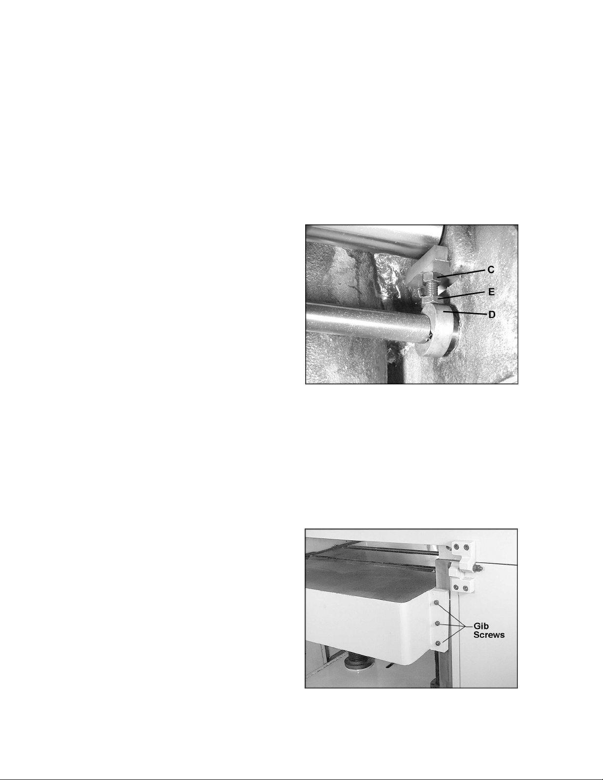
zero, reach beneath the table with a wrench
and loosen the hex nut (C, Figure 13) which
is above the cam (D, Figure 13) near the
end of the roller that needs adjusting. Rotate
the hex cap screw (E, Figure 13) until the
gauge reads zero.
6. Repeat the process for the left side of the
table roller, and then recheck the right side.
It is important that both ends of the table
rollers be the same height to help prevent
skewing of the board as it feeds through the
machine.
7. Re-tighten the hex nuts (C, Figure 13) on
both ends of the table roller.
8. Repeat the procedure for the second table
roller.
Table Adjustments
The planer table is raised and lowered by twin
screws supported on bearings, and is guided by
machined surfaces on the side panels. The fit-
up to prevent the table from rocking is controlled
by gibs. See Figure 14. These gibs should be
adjusted individually using the three gib screws
provided so that the ways are lightly contacting
on all four surfaces. The gibs should be tight
enough to prevent rocking or movement of the
table when the planer is in operation.
To perform accurate planing the table must be
parallel with the cutterhead. Lack of parallelism
results in a taper over the width of the board. To
check parallelism do the following:
1. Place a gauge on the table and contacting a
knife insert at the apex of its arc, Do this at
each end of the cutterhead and compare the
measurements.
2. If the table is not parallel to the cutterhead,
place the gauge at the end that needs to be
raised.
Figure 13
Figure 14

17
3. Loosen the three socket head cap screws
(A, Figure 15) beneath the table.
4. Place a rod-like object (such as a hex
wrench) into one of the open holes (B,
Figure 15) and turn the shaft (C, Figure 15)
to raise the table until the gauge reads the
proper measurement. Or, the same effect
can be achieved by lowering the other side
of the table.
5. Re-tighten the socket head cap screws (A,
Figure 15).
Test Cutting and
Troubleshooting
Using a piece of semi-finished stock, set up for a
1/16” (1.59mm) deep cut with the quick-set table
roller setting at zero. Start the machine and,
standing to one side of the table, begin feeding
the stock into the machine.
Never stand directly behind
stock or allow anyone else to do so, and do
not bend down to see how stock is feeding.
Should a kickback occur, serious or fatal
injury could result.
The infeed roller should take the material and
force it under the chipbreaker and cutterhead. If
the material feeds through effortlessly, examine
the finished cut carefully for imperfections.
Learning to read a board for imperfections will
save hours in adjusting a planer to operate
properly.
Following are some problems that may arise
and their probable remedies. The illustrations
are exaggerated for clarity. (Pages 37-39 also
contain Troubleshooting remedies).
Feed Restriction
This is caused either by the table rollers being
set too low for roughing operations or from a low
pressure bar. About 90 percent of the time, the
pressure bar is too low. As the sharp edge of the
knife inserts wear, you must compensate for this
wear by slightly raising the pressure bar an
equal amount on each side. Your first indication
of knife wear is hesitation in feed of the material
through the machine after it leaves the
corrugated infeed roller on its way out of the
machine. Disconnect machine from power
and adjust the pressure bar accordingly. The
material will free up and feed through smoothly
when the planer is restarted.
Never attempt pressure bar
adjustment while the machine is connected
to power.
Figure 15
 Loading...