


Operating Instructions and Parts Manual
10-inch Table Saw
Model 66
shown with optional extension table and legs, mobile base, and motor cover
WMH TOOL GROUP |
|
2420 Vantage Drive |
Part No. M-0460231NT |
Elgin, Illinois 60123 |
|
Ph.: 800-274-6848 |
Revision G 1/05 |
www.wmhtoolgroup.com |
Copyright © WMH Tool Group |

This manual has been prepared for the owner and operators of a Powermatic 66 Table Saw. Its purpose, aside from machine operation, is to promote safety using accepted operating and maintenance procedures. To obtain maximum life and efficiency from your table saw and to aid in using it safely, please read this manual thoroughly and follow the instructions carefully.
Warranty and Service
WMH Tool Group warrants every product it sells. If one of our tools needs service or repair, one of our Authorized Repair Stations located throughout the United States can provide quick service or information.
In most cases, a WMH Tool Group Repair Station can assist in authorizing repair work, obtaining parts, or perform routine or major maintenance repair on your Powermatic product.
For the name of an Authorized Repair Station in your area, please call 1-800-274-6848, or visit our web site at www.wmhtoolgroup.com
More Information
Remember, WMH Tool Group is consistently adding new products to the line. For complete, up-to-date product information, check with your local WMH Tool Group distributor, or visit our web site at www.wmhtoolgroup.com
WMH Tool Group Warranty
WMH Tool Group makes every effort to assure that its products meet high quality and durability standards and warrants to the original retail consumer/purchaser of our products that each product be free from defects in materials and workmanship as follows: 1 YEAR LIMITED WARRANTY ON ALL PRODUCTS UNLESS SPECIFIED OTHERWISE. This Warranty does not apply to defects due directly or indirectly to misuse, abuse, negligence or accidents, normal wear-and-tear, repair or alterations outside our facilities, or to a lack of maintenance.
WMH TOOL GROUP LIMITS ALL IMPLIED WARRANTIES TO THE PERIOD SPECIFIED ABOVE, BEGINNING FROM THE DATE THE PRODUCT WAS PURCHASED AT RETAIL. EXCEPT AS STATED HEREIN, ANY IMPLIED WARRANTIES OR MERCHANTABILITY AND FITNESS ARE EXCLUDED. SOME STATES DO NOT ALLOW LIMITATIONS ON HOW LONG THE IMPLIED WARRANTY LASTS, SO THE ABOVE LIMITATION MAY NOT APPLY TO YOU. IN NO EVENT SHALL WMH TOOL GROUP BE LIABLE FOR DEATH, INJURIES TO PERSONS OR PROPERTY, OR FOR INCIDENTAL, CONTINGENT, SPECIAL, OR CONSEQUENTIAL DAMAGES ARISING FROM THE USE OF OUR PRODUCTS. SOME STATES DO NOT ALLOW THE EXCLUSION OR LIMITATION OF INCIDENTAL OR CONSEQUENTIAL DAMAGES, SO THE ABOVE LIMITATION OR EXCLUSION MAY NOT APPLY TO YOU.
To take advantage of this warranty, the product or part must be returned for examination, postage prepaid, to an Authorized Repair Station designated by our office. Proof of purchase date and an explanation of the complaint must accompany the merchandise. If our inspection discloses a defect, we will either repair or replace the product at our discretion, or refund the purchase price if we cannot readily and quickly provide a repair or replacement. We will return the repaired product or replacement at WMH Tool Group’s expense, but if it is determined there is no defect, or that the defect resulted from causes not within the scope of WMH Tool Group’s warranty, then the user must bear the cost of storing and returning the product. This warranty gives you specific legal rights; you may also have other rights, which vary from state to state.
WMH Tool Group sells through distributors only. Members of the WMH Tool Group reserve the right to effect at any time, without prior notice, alterations to parts, fittings and accessory equipment, which they may deem necessary for any reason whatsoever.
2
Table of Contents |
|
Warranty and Service .............................................................................................................................. |
2 |
Warning................................................................................................................................................... |
4 |
Introduction.............................................................................................................................................. |
6 |
Specifications .......................................................................................................................................... |
6 |
Unpacking ............................................................................................................................................... |
7 |
Contents of the Shipping Container ...................................................................................................... |
7 |
Installation and Assembly ........................................................................................................................ |
8 |
Mounting Extension Wings ................................................................................................................... |
8 |
Installing Blade..................................................................................................................................... |
9 |
Mounting Rails and Accu-Fence ......................................................................................................... |
9 |
Optional Wood Extension Table ........................................................................................................... |
9 |
Splitter and Guard Assembly ................................................................................................................ |
9 |
Motor Cover ....................................................................................................................................... |
10 |
Grounding Instructions........................................................................................................................... |
10 |
Extension Cords................................................................................................................................. |
11 |
Adjustments........................................................................................................................................... |
11 |
Blade Raising and Tilting.................................................................................................................... |
11 |
Miter Slot Alignment ........................................................................................................................... |
11 |
Tilt Stop Adjustment ........................................................................................................................... |
12 |
Miter Gauge Adjustment..................................................................................................................... |
12 |
Belt Tensioning .................................................................................................................................. |
12 |
Splitter Alignment ............................................................................................................................... |
13 |
Insert Adjustment ............................................................................................................................... |
13 |
Arbor and Arbor Bearing Removal...................................................................................................... |
13 |
Blade Raising Mechanism Adjustment................................................................................................ |
13 |
Tilting Mechanism Adjustment............................................................................................................ |
14 |
Operating Instructions for Table Saws.................................................................................................... |
14 |
Rip Sawing......................................................................................................................................... |
16 |
Resawing ........................................................................................................................................... |
17 |
Crosscutting....................................................................................................................................... |
17 |
Bevel and Miter Operations ................................................................................................................ |
18 |
Dado Cutting...................................................................................................................................... |
19 |
Safety Devices ................................................................................................................................... |
19 |
Maintenance.......................................................................................................................................... |
20 |
Optional Accessories ............................................................................................................................. |
23 |
Replacement Parts ................................................................................................................................ |
23 |
Parts List: Trunnion Assembly ............................................................................................................ |
24 |
Trunnion Assembly............................................................................................................................. |
26 |
Parts List: Miter Gauge....................................................................................................................... |
27 |
Parts List: Splitter and Guard Assembly.............................................................................................. |
28 |
Splitter and Guard Assembly .............................................................................................................. |
29 |
Parts List: Stand Assembly................................................................................................................. |
30 |
Stand Assembly ................................................................................................................................. |
31 |
Parts List: Table Extension and Legs (Optional Accessory)................................................................. |
32 |
Electrical Connections ........................................................................................................................... |
33 |
Maintenance Checklist........................................................................................................................... |
37 |
3

1.Read and understand the entire owners manual before attempting assembly or operation.
2.Read and understand the warnings posted on the machine and in this manual. Failure to comply with all of these warnings may cause serious injury.
3.Replace the warning labels if they become obscured or removed.
4.This table saw is designed and intended for use by properly trained and experienced personnel only. If you are not familiar with the proper and safe operation of a table saw, do not use until proper training and knowledge have been obtained.
5.Do not use this table saw for other than its intended use. If used for other purposes, WMH Tool Group disclaims any real or implied warranty and holds itself harmless from any injury that may result from that use.
6.Always wear approved safety glasses/face shields while using this table saw. Everyday eyeglasses only have impact resistant lenses; they are not safety glasses.
7.Before operating this table saw, remove tie, rings, watches and other jewelry, and roll sleeves up past the elbows. Remove all loose clothing and confine long hair. Non-slip footwear or anti-skid floor strips are recommended. Do not wear gloves.
8.Wear ear protectors (plugs or muffs) during extended periods of operation.
9.Some dust created by power sanding, sawing, grinding, drilling and other construction activities contain chemicals known to cause cancer, birth defects or other reproductive harm. Some examples of these chemicals are:
•Lead from lead based paint.
•Crystalline silica from bricks, cement and other masonry products.
•Arsenic and chromium from chemically treated lumber.
Your risk of exposure varies, depending on how often you do this type of work. To reduce your exposure to these chemicals, work in a well-ventilated area and work with approved safety equipment, such as face or dust masks that are specifically designed to filter out microscopic particles.
10.Do not operate this machine while tired or under the influence of drugs, alcohol or any medication.
11.Make certain the switch is in the OFF position before connecting the machine to the power supply.
12.Make certain the machine is properly grounded.
13.Make all machine adjustments or maintenance with the machine unplugged from the power source. A machine under repair should be RED TAGGED to show it must not be used until maintenance is complete.
14.Remove adjusting keys and wrenches. Form a habit of checking to see that keys and adjusting wrenches are removed from the machine before turning it on.
15.Keep safety guards in place at all times when the machine is in use. If removed for maintenance purposes, use extreme caution and replace the guards immediately.
16.Check the alignment of the splitter, fence and miter slot to the blade. A caution decal is installed on each guard and splitter to remind the operator of the dangers of misalignment.
17.Check damaged parts. Before further use of the machine, a guard or other part that is damaged should be carefully checked to determine that it will operate properly and perform its intended function. Check for alignment of moving parts, binding of moving parts, breakage of parts, mounting and any other conditions that may affect its operation. A guard or other part that is damaged should be properly repaired or replaced.
18.Provide for adequate space surrounding work area and non-glare, overhead lighting.
19.Keep the floor around the machine clean and free of scrap material, oil and grease.
4

20.Keep visitors a safe distance from the work area. Keep children away.
21.Make your workshop child proof with padlocks, master switches or by removing starter keys.
22.Give your work undivided attention. Looking around, carrying on a conversation and “horse-play” are careless acts that can result in serious injury.
23.Maintain a balanced stance at all times so that you do not fall or lean against the blade or other moving parts. Do not overreach or use excessive force to perform any machine operation.
24.Use the right tool at the correct speed and feed rate. Do not force a tool or attachment to do a job for which it was not designed. The right tool will do the job better and safer.
25.Use recommended accessories; improper accessories may be hazardous.
26.Maintain tools with care. Keep blade sharp and clean for the best and safest performance. Follow instructions for lubricating and changing accessories.
27.Check the saw blade for cracks or missing teeth. Do not use a cracked or dull blade or one with missing teeth or improper set. Make sure the blade is securely locked on the arbor.
28.Keep hands clear of the blade area. Do not reach past the blade to clear parts or scrap with the saw blade running. Never saw freehand. Avoid awkward operations and hand positions where a sudden slip could cause your hand to contact the blade.
29.Do not attempt to saw boards with loose knots or with nails or other foreign material, on its surface. Do not attempt to saw twisted, warped, bowed or “in wind” stock unless one edge has been jointed for guiding purposes prior to sawing.
30.Do not attempt to saw long or wide boards unsupported where spring or weight could cause the board to shift position.
31.Always use the splitter, blade guard, push stick and other safety devices for all operations where they can be used. On operations such as dadoing or molding where the blade guard cannot be used, use feather boards, fixtures and other safety devices and use extreme caution. Reinstall the splitter and blade guard immediately after completing the operation that required their removal.
32.Be sure the saw blade rotates clockwise when viewed from the motor side (left side) of the machine.
33.Turn off the machine before cleaning. Use a brush or compressed air to remove chips or debris — do not use your hands.
34.Do not stand on the machine. Serious injury could occur if the machine tips over.
35.Never leave the machine running unattended. Turn the power off and do not leave the machine until it comes to a complete stop.
36.Remove loose items and unnecessary work pieces from the area before starting the machine.
Familiarize yourself with the following safety notices used in this manual:
 This means that if precautions are not heeded, it may result in minor injury and/or possible machine damage.
 This means that if precautions are not heeded, it may result in serious injury or possibly even death.
- - SAVE THESE INSTRUCTIONS - -
5
Introduction
This manual is provided by WMH Tool Group covering the safe operation and maintenance procedures for a Powermatic Model 66 Table Saw. This manual contains instructions on installation, safety precautions, general operating procedures, maintenance instructions and parts breakdown. This machine has been designed and constructed to provide years of trouble free operation if used in accordance with instructions set forth in this manual. If there are any questions or comments, please contact either your local supplier or WMH Tool Group. WMH Tool Group can also be reached at our web site: www.wmhtoolgroup.com.
Specifications |
|
Model number........................................................................................................................................ |
66 |
Maximum motor size......................................................................................................... |
5HP, 3600 RPM |
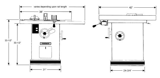
Table size with standard extensions (L x W)(in.)....................................................................... |
37-1/2 x 28 |
Table size without extension (L x W)(in.).................................................................................. |
21-1/2 x 28 |
Rip fence (L x W x H)(in.)................................................................................................ |
41-3/4 x 4 x 2-1/2 |
Arbor diameter (in.)............................................................................................................................... |
5/8 |
Saw blade diameter (in.) ........................................................................................................................ |
10 |
Maximum speed of 10” saw blade (SFM) ........................................................................................ |
11,000 |
Blade tilt maximum (deg.) ...................................................................................................................... |
45 |
Maximum depth of cut (in.).......................................................... |
3-1/8 at 90-degrees; 2-1/8 at 45-degrees |
Maximum cut to right of saw blade with standard extension (in.)............................................................. |
25 |
Maximum width of cutoff in front of saw in 1” stock (in.).......................................................................... |
15 |
Maximum width of cutoff in front of saw in 3-1/8” stock (in.).............................................................. |
12-1/4 |
Maximum diameter of dado (in.)............................................................................................................... |
8 |
Maximum width of dado cut (in.)........................................................................................................ |
13/16 |
Drive belts .................................................................................................................... |
3VX (two required) |
Table height to floor (in.) ........................................................................................................................ |
34 |
Dust port diameter (in.) ............................................................................................................................ |
4 |
Shipping weight with motor, fence and rails (lbs.) ................................................................................. |
614 |
The above specifications were current at the time this manual was published, but because of our policy of continuous improvement, WMH Tool Group reserves the right to change specifications at any time and without prior notice, without incurring obligations.
6

Unpacking
Open shipping container and check for shipping damage. Report any damage immediately to your distributor and shipping agent. Do not discard any shipping material until the Table Saw is assembled and running properly.
Compare the contents of your container with the following parts list to make sure all parts are intact. Missing parts, if any, should be reported to your distributor. Read the instruction manual thoroughly for assembly, maintenance and safety instructions.
Contents of the Shipping Container
Box 1: 1 Table Saw
2 |
Extension Wings |
1 |
Miter Gauge |
1 |
Owner’s Manual |
1 |
Warranty Card |
Box 2: 1 Splitter and Guard Assembly |
|
1 |
Splitter Support Shaft |
2 Arbor Wrenches
1Hardware Bag* Box 3: 1 Accu-Fence
1Lock Handle
1Accu-Fence Owner’s Manual Box 4: 1 Front Rail
1Rear Rail
1Guide Tube
1Hardware Bag Box 5: 1 Motor Cover
2Self-Tapping Screws
Optional:
Box 6: Formica Top Extension Table
Box 7: Legs for Extension Table
*The contents of the hardware bag are illustrated below. The contents of the AccuFence and Rail hardware can be found in the Accu-Fence manual.
Contents of Hardware Bag:
Read and understand the entire contents of this manual before attempting set-up or operation! Failure to comply may cause serious injury.
7
Installation and Assembly
Tools required for assembly:
7/16, 9/16, 3/8 and 1/2” wrenches 1/8 and 3/32” hex wrenches
Flat head screwdriver
Hammer and wood block (or rubber hammer)
1.Remove box and wood crating completely from around saw.
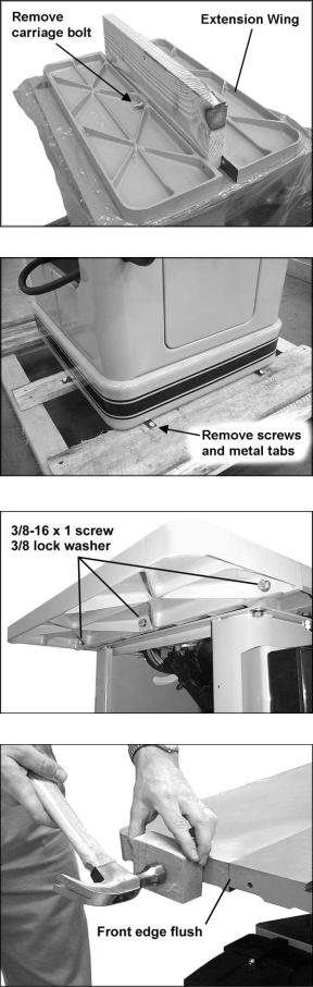
2.Use a 9/16” wrench to remove the carriage bolt, hex nut and washer holding the extension wings together (Figure 1). Set extension wings aside for later installation.
3.With a 7/16” wrench, remove the lag screws (Figure 2) holding the saw to the wood pallet. Carefully slide the saw from the pallet onto the floor.
4.Tilt the saw, and pop off the metal tabs (Figure 2) that secured the saw to the pallet, by pushing down on them with your foot.
The Table Saw should be placed in an area with a sturdy level floor, good ventilation and sufficient lighting. Leave enough space around the machine for mounting extension wings and rail assemblies, and loading and off-loading stock and general maintenance work.
Exposed metal surfaces, such as the table top and extension wings, have been given a protective coating at the factory. This should be removed with a soft cloth moistened with kerosene. Do not use acetone, gasoline, or lacquer thinner for this purpose. Do not use solvents on plastic parts, and do not use an abrasive pad because it may scratch the surfaces.
Mounting Extension Wings
1.Mount the cast iron extension wings using six 3/8-16 x 1 hex head screws and six 3/8 lock washers. See Figure 3. Have an assistant hold the extension wing up to the table, and insert the screws and washers. Finger tighten only.
NOTE: If an assistant is not available, hold the wing in vertical position up to the saw table, insert the middle screw and lock washer finger tight, then pivot the wing to level position. Insert the other two screws and washers finger tight.
2.It is important that the front edge of the wing is flush with the front edge of saw table. See Figure 4.
8
Figure 1
Figure 2
Figure 3
Figure 4
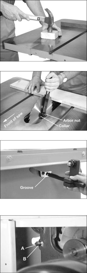
3.Level the extension wing with the saw table across its entire width, using a straight edge and hammer with block of wood (or rubber hammer). See Figure 5. As each area of the wing becomes flush with the table, tighten the screw under that area. Continue until all three screws are fully tightened.
4.Repeat for the other extension wing.
Installing Blade
NOTE: The blade must be mounted first before rails can be adjusted.
To install or replace a blade, proceed as follows:
 Use care when working with or around sharp saw blade.
1.Disconnect machine from power source.
2.Remove table insert, then remove arbor nut and collar.
3.Install blade, making sure the cutting teeth at the top of the blade point toward the front of the saw.
4.Slide the collar on to the arbor and start the arbor nut on the threads. (NOTE: Righthand threads; turn clockwise to tighten.) Snug the arbor nut against the collar and blade with the provided arbor wrench, while holding blade with thumb and finger tips.
5.Wedge a block of wood between the blade and table to prevent blade rotation, then tighten the arbor nut securely with the arbor wrench. See Figure 6.
Mounting Rails and Accu-Fence
With the extension wings properly aligned, the rail and fence assembly can now be mounted to the saw. Consult the separate Accu-Fence manual for instructions.
Optional Wood Extension Table
For instructions on mounting the accessory wood extension table, or router table, consult your Accu-Fence manual.
Splitter and Guard Assembly
1.Insert the grooved end of the splitter support shaft through slot in rear of saw and into hole in trunnion. See Figure 7. Make sure the square head setscrew (A, Figure 8) is backed out enough to allow easy insertion of the splitter support shaft.
9
Figure 5
Figure 6
Figure 7
Figure 8
2.With a 3/8" wrench, reach through the motor opening in the stand and tighten the square head setscrew (A, Figure 8) into the groove of the shaft. (NOTE: The groove will be in the proper position if the end of the shaft is made flush with the opposite side of the trunnion hole.) Then tighten the hex nut (B, Figure 8) up against the trunnion.
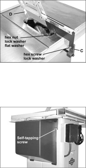
3.The upright member of the rear splitter support (C, Figure 9) must be oriented toward the right of the shaft, as observed from the rear of the saw.
4.Mount the splitter assembly to the two adjusting screws. See Figure 9. Place the two flanges of the splitter assembly onto the screws as shown. Snug the screws. (NOTE: Make sure the front shield (D, Figure 9) faces in toward the blade)
5.The splitter and guard assembly must be aligned with the blade before operating the saw. Adjust the splitter according to the directions on page 13, "Splitter Alignment."
Motor Cover
1.Locate the two 1/4-20 self tapping sheet metal screws and install them in the punched holes on the saw cabinet. Do not screw down all the way, but leave the heads about 1/4" from the surface. See Figure 10.
2.Lift the motor cover over these screws with the cover's bottom lip inside the saw's cabinet.
3.Tighten the two screws.
Figure 9
Figure 10
Grounding Instructions
 Electrical connections must be made by a qualified electrician in compliance with all relevant codes. This machine must be properly grounded to help prevent electrical shock and possible fatal injury.
A power plug is not provided with the Model 66. You may either connect the proper UL/CSA listed plug or “hardwire” the machine directly to your electrical panel provided there is a disconnect near the machine for the operator. Consult electrical drawings on pages 33-36 for further clarification of wiring setup.
This machine must be grounded. Grounding provides a path of least resistance to help divert current away from the operator in case of electrical malfunction.
Recommended Gauges (AWG) of Extension Cords
|
|
Extension Cord Length * |
|
||||
|
|
|
|
|
|
|
|
Amps |
25 |
50 |
75 |
100 |
150 |
200 |
|
feet |
feet |
feet |
feet |
feet |
feet |
||
|
|||||||
|
|
|
|
|
|
|
|
< 5 |
16 |
16 |
16 |
14 |
12 |
12 |
|
|
|
|
|
|
|
|
|
5 to 8 |
16 |
16 |
14 |
12 |
10 |
NR |
|
|
|
|
|
|
|
|
|
8 to 12 |
14 |
14 |
12 |
10 |
NR |
NR |
|
|
|
|
|
|
|
|
|
12 to 15 |
12 |
12 |
10 |
10 |
NR |
NR |
|
|
|
|
|
|
|
|
|
15 to 20 |
10 |
10 |
10 |
NR |
NR |
NR |
|
|
|
|
|
|
|
|
|
21 to 30 |
10 |
NR |
NR |
NR |
NR |
NR |
|
|
|
|
|
|
|
|
|
*based on limiting the line voltage drop to 5V at 150% of the rated amperes.
NR: Not Recommended.
Figure 11
10

Make sure the voltage of your power supply matches the specifications on the motor plate of the machine.
Extension Cords
If an extension cord is necessary, make sure the cord rating is suitable for the amperage listed on the machine's motor plate. An undersize cord will cause a drop in line voltage resulting in loss of power and overheating.
The chart in Figure 11 shows the correct size cord to use based on cord length and motor plate amp rating. If in doubt, use the next heavier gauge. The smaller the gauge number the heavier the cord.
Adjustments
Blade Raising and Tilting
The front handwheel (A, Figure 12) controls the raising and lowering of the blade. The side handwheel (B, Figure 12) controls blade tilt, which is indicated by the scale (C, Figure 12). The lock knobs (D, Figure 12) are used to lock the setting of the handwheels.
Miter Slot Alignment
Disconnect machine from power source before making this adjustment.
1.To check the alignment of the mitre slot to the blade, raise the blade to its maximum height at the 0 degree (vertical) position.
2.Mark one tooth with a grease pencil and position the tooth slightly above the top edge of the table at the front.
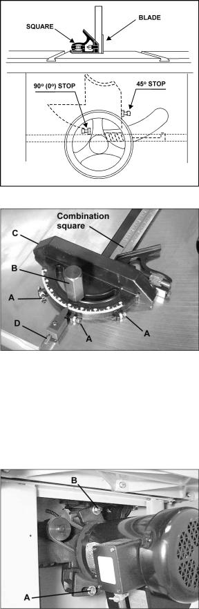
3.Raise the miter gauge slightly out of its slot to serve as a shoulder. Using a combination square against the side of the bar, slide the scale over until it touches the tip of the blade, and lock the scale in position. See Figure 13.
4.Rotate the marked tooth so that it is slightly above the table top at the rear and, using the square as before, check whether the distance to the blade is the same. See Figure 14. If the distance is not the same, loosen the three mounting screws that lock the table to the cabinet (two in front, one in back) as shown in Figure 15, and nudge the table to bring the miter slot in line with the blade.
Figure 12
Figure 13
Figure 14
Figure 15
11
5.The blade must be kept centered with the slot in the table insert to ensure clearance at both the 90 degree and 45 degree positions. After alignment, secure the table to the cabinet by re-tightening the three mounting screws (Figure 15).
Tilt Stop Adjustment
Using a combination square, check the 90 degree (0) and 45 degree stops. (Figure 16 shows the 90 degree stop being checked.) Adjust stop positions if required, using the stop screws as shown. Check the accuracy of the pointer at 90 degrees (0) and re-adjust if required.
Miter Gauge Adjustment
1.Slide the miter gauge into one of the slots on the table top.
2.The miter gauge is equipped with individually adjustable index stops at 90 degrees and 45 degrees right and left. The index stops can be adjusted by loosening the hex nuts and turning the three adjusting screws (A, Figure 17) as needed. After setting each stop, retighten the hex nut.
3.To operate the miter gauge, loosen lock handle (B, Figure 17) and move the body of the miter gauge (C, Figure 17) to the desired angle. The miter gauge body is set to stop at 0 degrees and 45 degrees left or right. To move the miter gauge beyond these points, the stop rod (D, Figure 17), must be pulled out.
4.If accurate crosscutting work is to be done using the miter gauge, check its squareness to the slot with a square as shown in Figure 17. Re-adjust the stop position as required.
Belt Tensioning
The saw is equipped with a set of two matched belts. If they should need replacement, replace the complete set.
To tension the belts:
Loosen the hex screw (A, Figure 18) and nut (B, Figure 18) on the motor bracket. Pivot the motor and bracket to the right. Retighten screw (A, Figure 18) and nut (B, Figure 18).
To remove and replace the belts, loosen the screw (A, Figure 18) and nut (B, Figure 18) and rotate the motor and bracket to the left as far as possible. Remove one belt at a time. After installing new belts, re-tension as indicated.
Figure 16
Figure 17
Figure 18
12
 Loading...