


 Loading...
This Manual is Bookmarked
Operating Instructions and Parts Manual
20-inch Planer
Models 209 and 209HH
WMH TOOL GROUP |
|
|
2420 Vantage Drive |
|
|
Elgin, Illinois 60124 |
Part No. M-0260283 |
|
Ph.: 800-274-6848 |
Revision D1 |
11/06 |
www.wmhtoolgroup.com |
Copyright © WMH Tool |
Group |

Warranty and Service
WMH Tool Group, Inc., warrants every product it sells. If one of our tools needs service or repair, one of our Authorized Service Center located throughout the United States can give you quick service. In most cases, any of these WMH Tool Group Authorized Service Centers can authorize warranty repair, assist you in obtaining parts, or perform routine maintenance and major repair on your POWERMATIC® tools. For the name of an Authorized Service Center in your area call 1-800-274-6848.
MORE INFORMATION
WMH Tool Group is consistently adding new products to the line. For complete, up-to-date product information, check with your local WMH Tool Group distributor, or visit powermatic.com.
WARRANTY
POWERMATIC products carry a limited warranty which varies in duration based upon the product.
WHAT IS COVERED?
This warranty covers any defects in workmanship or materials subject to the exceptions stated below. Cutting tools, abrasives and other consumables are excluded from warranty coverage.
WHO IS COVERED?
This warranty covers only the initial purchaser of the product.
WHAT IS THE PERIOD OF COVERAGE?
The general POWERMATIC warranty lasts for the time period specified in the product literature of each product.
WHAT IS NOT COVERED?
The Five Year Warranty does not cover products used for commercial, industrial or educational purposes. Products with a Five Year Warranty that are used for commercial, industrial or education purposes revert to a One Year Warranty. This warranty does not cover defects due directly or indirectly to misuse, abuse, negligence or accidents, normal wear-and-tear, improper repair or alterations, or lack of maintenance.
HOW TO GET SERVICE
The product or part must be returned for examination, postage prepaid, to a location designated by us. For the name of the location nearest you, please call 1-800-274-6848.
You must provide proof of initial purchase date and an explanation of the complaint must accompany the merchandise. If our inspection discloses a defect, we will repair or replace the product, or refund the purchase price, at our option.
We will return the repaired product or replacement at our expense unless it is determined by us that there is no defect, or that the defect resulted from causes not within the scope of our warranty in which case we will, at your direction, dispose of or return the product. In the event you choose to have the product returned, you will be responsible for the handling and shipping costs of the return.
HOW STATE LAW APPLIES
This warranty gives you specific legal rights; you may also have other rights which vary from state to state.
LIMITATIONS ON THIS WARRANTY
WMH TOOL GROUP LIMITS ALL IMPLIED WARRANTIES TO THE PERIOD OF THE LIMITED WARRANTY FOR EACH PRODUCT. EXCEPT AS STATED HEREIN, ANY IMPLIED WARRANTIES OR MERCHANTABILITY AND FITNESS ARE EXCLUDED. SOME STATES DO NOT ALLOW LIMITATIONS ON HOW LONG THE IMPLIED WARRANTY LASTS, SO THE ABOVE LIMITATION MAY NOT APPLY TO YOU.
WMH TOOL GROUP SHALL IN NO EVENT BE LIABLE FOR DEATH, INJURIES TO PERSONS OR PROPERTY, OR FOR INCIDENTAL, CONTINGENT, SPECIAL, OR CONSEQUENTIAL DAMAGES ARISING FROM THE USE OF OUR PRODUCTS. SOME STATES DO NOT ALLOW THE EXCLUSION OR LIMITATION OF INCIDENTAL OR CONSEQUENTIAL DAMAGES, SO THE ABOVE LIMITATION OR EXCLUSION MAY NOT APPLY TO YOU.
WMH Tool Group sells through distributors only. The specifications in WMH catalogs are given as general information and are not binding. Members of WMH Tool Group reserve the right to effect at any time, without prior notice, those alterations to parts, fittings, and accessory equipment which they may deem necessary for any reason whatsoever.
2
Table of Contents |
|
Warranty and Service.................................................................................................................................... |
2 |
Table of Contents.......................................................................................................................................... |
3 |
Warning......................................................................................................................................................... |
4 |
Introduction ................................................................................................................................................... |
6 |
Features ........................................................................................................................................................ |
6 |
Specifications ................................................................................................................................................ |
7 |
Unpacking ..................................................................................................................................................... |
8 |
Assembly....................................................................................................................................................... |
9 |
Knife Gauge (model 209 only)................................................................................................................... |
9 |
Handwheel................................................................................................................................................. |
9 |
Extension Tables ..................................................................................................................................... |
10 |
Dust Hood................................................................................................................................................ |
10 |
Electrical Connections ............................................................................................................................. |
10 |
Extension Cords ...................................................................................................................................... |
11 |
Adjustments ................................................................................................................................................ |
11 |
Belt Tension............................................................................................................................................. |
11 |
Table Rollers ........................................................................................................................................... |
11 |
Cutterhead............................................................................................................................................... |
12 |
Knife Adjustments (Model 209 only)........................................................................................................ |
12 |
Replacing and Re-setting Knives (Model 209 only) ................................................................................ |
13 |
Replacing or Rotating Knife Inserts (Model 209HH only)........................................................................ |
14 |
Work Table Parallel to Cutterhead .......................................................................................................... |
15 |
Know the Transmitting Rollers of Your Planer (Figure 23)..................................................................... |
15 |
Anti-Kickback Fingers.............................................................................................................................. |
16 |
Infeed and Outfeed Roller Spring Tension.............................................................................................. |
16 |
Height of Infeed Roller, Chipbreaker, Pressure Bar and Outfeed Roller ................................................ |
16 |
Infeed Roller Height................................................................................................................................. |
17 |
Chipbreaker Height.................................................................................................................................. |
17 |
Pressure Bar Height ................................................................................................................................ |
18 |
Chip Deflector.......................................................................................................................................... |
18 |
Feed Speed Control ................................................................................................................................ |
18 |
Changing Accessories for Lowest Feed Speed ...................................................................................... |
18 |
Return Rollers.......................................................................................................................................... |
19 |
Depth of Cut ............................................................................................................................................ |
19 |
Maintenance................................................................................................................................................ |
20 |
Lubrication ............................................................................................................................................... |
20 |
Troubleshooting: Operating Problems ........................................................................................................ |
22 |
Troubleshooting: Mechanical and Electrical Problems ............................................................................... |
23 |
Optional Accessories .................................................................................................................................. |
24 |
Replacement Parts...................................................................................................................................... |
24 |
Cutterhead Assembly .............................................................................................................................. |
25 |
Parts List: Cutterhead Assembly ............................................................................................................. |
26 |
Base Assembly........................................................................................................................................ |
28 |
Parts List: Base Assembly....................................................................................................................... |
29 |
Gearbox Assembly .................................................................................................................................. |
30 |
Parts List: Gearbox Assembly ................................................................................................................. |
31 |
Stand Assembly....................................................................................................................................... |
32 |
Parts List: Stand Assembly ..................................................................................................................... |
33 |
Parts List: Table Assembly...................................................................................................................... |
34 |
Electrical Connections – 3 Phase, 230 Volt only ........................................................................................ |
36 |
Electrical Connections – 3 Phase, 460 Volt only ........................................................................................ |
37 |
3

As with all machines, there is a certain amount of hazard involved with the use of this planer. Use the machine with the respect and caution demanded where safety precautions are concerned. When normal safety precautions are overlooked or ignored, personal injury to the operator can result.
Read, understand and follow the safety and operating instructions found in this manual. Know the limitations and hazards associated with this machine.
Electrical grounding. Make certain that the machine frame is electrically grounded and that a ground lead is included in the incoming electrical service. In cases where a cord and plug are used, make certain that the grounding plug connects to a suitable ground. Follow the grounding procedure indicated in the National Electrical Code.
Eye safety. Wear an approved safety shield, goggles, or glasses to protect eyes. (NOTE: Common eyeglasses are only impact-resistant, they are not safety glasses.)
Personal protection. Before operating the machine, remove tie, rings, watch and other jewelry and roll up sleeves above the elbows. Remove all loose outer clothing and confine long hair. Protective type footwear should be used. Where the noise exceeds the level of exposure allowed in Section 1910.95 of the OSHA Regulations, use hearing protective devices. Do not wear gloves.
Guards. Keep the machine guards in place for every operation for which they can be used. If any guards are removed for maintenance, DO NOT OPERATE the machine until the guards are reinstalled.
Placement. Place machine so that potential kickback area is not in line with aisles, doorways, wash stations, or other work areas.
Work area. Keep the floor around the machine clean and free of scrap material, saw dust, oil and other liquids to minimize the danger of tripping or slipping. Be sure the table is free of all scrap, foreign material and tools before starting to cut. Make certain the work area is well lighted and that a proper exhaust system is used to minimize dust. It is recommended that anti-skid floor strips are used on the floor area where the operator normally stands and that each machine’s work area be marked off. Provide adequate work space around the machine.
Avoid accidental starting: Make certain motor switch is in off position before connecting power to the machine.
Operator position. Maintain a balanced stance and keep your body under control at all times. Stand to one side out of line with the table and make sure no one else is standing in line with the table.
Housekeeping. Before turning on machine, remove all extra equipment such as keys, wrenches, scrap, and cleaning rags away from the machine
Careless acts. Give the work you are doing your undivided attention. Looking around, carrying on a conversation, and “horseplay” are careless acts that can result in serious injury.
Disconnect machine before performing any service or maintenance or when changing blades. A machine under repair should be RED TAGGED to show it should not be used until the maintenance is complete.
Maintain tools in top condition. Keep tools sharp and clean for safe and best performance. Dull tools increase noise levels and can cause kickbacks and glazed surfaces. Check the condition and adjustment of the tools before making any cuts. Follow the sharpening instructions on knife grinding and jointing, installing and adjustments.
4
Hand safety. Keep hands outside the machine. NEVER reach under the guards to try to clear stock that stops feeding. Do not clear chips and sawdust with hands; use a brush. Do not have any part of the hands under that part of the board that is over the table when starting a cut; the infeed roll will engage the board and force it down against the table causing a pinching action. Do not operate machine while the gear cover is open.
Cutterhead rotation: Be sure cutterhead rotates under power in a counterclockwise direction when viewed from the main drive motor side.
Material condition: Do not plane boards with loose knots or with nails or any foreign material on its surface. Knife impact on these objects can cause the knives to be pulled out and cause them to shatter against the chipbreaker or pressure bar. Twisted, warped, or in wind stock should first be jointed on one surface before attempting to plane a parallel surface on the planer. Serious stock flaws cannot be removed by use of a planer alone.
Machine adjustments: Make all machine adjustments with power off except feed rate.
Job completion. If the operator leaves the machine area for any reason, the planer should be turned "off" and the cutterhead should come to a complete stop before his departure. In addition, if the operation is complete, he should clean the planer and the work area. Never clean the planer with power "on" and never use the hands to clear sawdust and debris; use a brush.
Replacement parts. Use only Powermatic or factory authorized replacement parts and accessories; otherwise the warranty and guarantee is null and void.
Misuse. Do not use this Powermatic planer for other than its intended use. If used for other purposes, Powermatic disclaims any real or implied warranty and holds itself harmless for any injury or damage which may result from that use.
If you are not thoroughly familiar with the operation of planers, obtain advice from your supervisor, instructor or other qualified person.
Drugs, alcohol, medication. Do not operate this machine while under the influence of drugs, alcohol, or any medication.
Health hazards. Some dust created by power sanding, sawing, grinding, drilling and other construction activities contains chemicals known to cause cancer, birth defects or other reproductive harm. Some examples of these chemicals are:
*Lead from lead-based paint.
*Crystalline silica from bricks and cement and other masonry products.
*Arsenic and chromium from chemically-treated lumber.
Your risk from these exposures varies, depending on how often you do this type of work. To reduce your exposure to these chemicals, work in a well-ventilated area, and work with approved safety equipment, such as those dust masks that are specifically designed to filter out microscopic particles.
Familiarize yourself with the following safety notices used in this manual:
 This means that if precautions are not heeded, it may result in minor injury and/or possible machine damage.
 This means that if precautions are not heeded, it may result in serious injury or possibly even death.
5
Introduction
This manual is provided by WMH Tool Group covering the safe operation and maintenance procedures for a Powermatic Model 209 and 209HH Planer. This manual contains instructions on installation, safety precautions, general operating procedures, maintenance instructions and parts breakdown. This machine has been designed and constructed to provide years of trouble free operation if used in accordance with instructions set forth in this manual. If there are any questions or comments, please contact either your local supplier or WMH Tool Group. WMH Tool Group can also be reached at our web site: www.wmhtoolgroup.com.
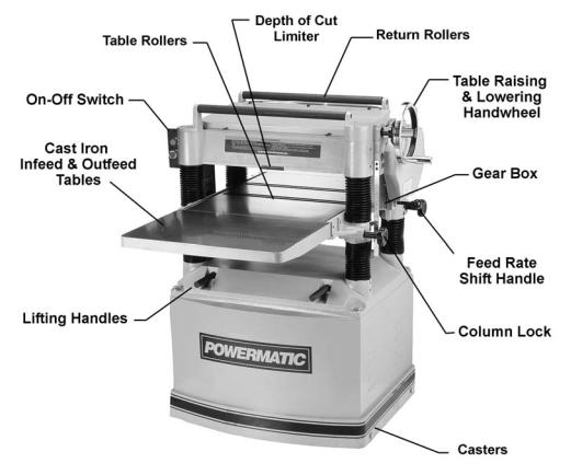
Features
Figure 1
6
Specifications
Model Number....................................................................... |
209-1 |
.......................................................209-3 |
Stock Number .................................................................. |
1791296 .................................................. |
1791297 |
Table Area (in.) ............................................................ |
25-3/4 x 20 .............................................. |
25 - 3/4 x 20 |
Maximum Planing Width (in.) ..................................................... |
20 ............................................................ |
20 |
Maximum Planing Thickness (in.) ................................................ |
8 .............................................................. |
8 |
Full Width Cutting Depth (in.).................................................. |
3/32 ......................................................... |
3/32 |
Minimum Planing Length (in.) ................................................ |
6-3/4 ........................................................ |
6-3/4 |
Knives........................................................................................... |
4 .............................................................. |
4 |
Blade Size (in.)............................................................ |
20 x 1 x 1/8 ............................................. |
20 x 1 x 1/8 |
Cutterhead Speed (RPM)...................................................... |
5,000 ....................................................... |
5,000 |
Cuts per Minute................................................................... |
20,000 ..................................................... |
20,000 |
Cutterhead Diameter (in.)..................................................... |
3-3/16 ...................................................... |
3-3/16 |
Feeding Speed (FPM).................................................... |
24 and 31 ................................................ |
24 and 31 |
Motor ........................................................ |
TEFC, 5HP, 1Ph, 230V .................. |
TEFC, 5HP, 3Ph, 230/460V* |
Dust Chute Diameter (in.) ............................................................ |
5 .............................................................. |
5 |
Overall Dimensions (LxWxH)(in.)................... |
26 x 36-5/8 x 41-3/8 ................................ |
26 x 36 - 5/8 x 41-3/8 |
Net Weight (lbs.) ...................................................................... |
770 .......................................................... |
770 |
Shipping Weight (lbs.) .............................................................. |
880 .......................................................... |
880 |
|
|
*pre - wired 230 volt |
Model Number................................................................. |
209HH-1 |
..................................................209HH-3 |
Stock Number .................................................................. |
1791315 |
.................................................. 1791316 |
Table Area (in.) ............................................................ |
25-3/4 x 20 .............................................. |
25-3/4 x 20 |
Maximum Planing Width (in.) ..................................................... |
20 ............................................................ |
20 |
Maximum Planing Thickness (in.) ................................................ |
8 .............................................................. |
8 |
Full Width Cutting Depth (in.).................................................. |
3/32 ......................................................... |
3/32 |
Minimum Planing Length (in.) ................................................ |
6-3/4 ........................................................ |
6-3/4 |
Knives.......................................................... |
132 four-sided inserts ............................. |
132 four - sided inserts |
Cutterhead Speed (RPM)...................................................... |
5,000 ....................................................... |
5,000 |
Cuts per Minute................................................................... |
20,000 ..................................................... |
20,000 |
Cutterhead Diameter (in.)..................................................... |
3-1/16 ...................................................... |
3-1/16 |
Feeding Speed (FPM).................................................... |
24 and 31 ................................................ |
24 and 31 |
Motor ........................................................ |
TEFC, 5HP, 1Ph, 230V .................. |
TEFC, 5HP, 3Ph, 230/460V* |
Dust Chute Diameter (in.) ............................................................ |
5 .............................................................. |
5 |
Overall Dimensions (LxWxH)(in.)................... |
26 x 36-5/8 x 41-3/8 ................................ |
26 x 36 - 5/8 x 41-3/8 |
Net Weight (lbs.) ...................................................................... |
801 .......................................................... |
801 |
Shipping Weight (lbs.) .............................................................. |
911 .......................................................... |
911 |
*pre-wired 230 volt
The above specifications were current at the time this manual was published, but because of our policy of continuous improvement, WMH Tool Group reserves the right to change specifications at any time and without prior notice, without incurring obligations.
7

Unpacking
Open shipping container and check for shipping damage. Report any damage immediately to your distributor and shipping agent. Do not discard any shipping material until the Planer is assembled and running properly.
Compare the contents of your container with the following parts list to make sure all parts are intact. Missing parts, if any, should be reported to your distributor. Read the instruction manual thoroughly for assembly, maintenance and safety instructions.
Crate Contents (Figure 2):
Models 209 and 209HH:
1Planer (not shown)
1Dust Hood
2Cast Iron Extension Tables
1 Handwheel
1 Handle
1 Low Speed Gear Kit (#6292822) containing:
1 50P Chain
1 12T Sprocket
3Open-End Wrenches (8-10,12-14,17-19mm)
4Hex Wrenches (3,4,5 and 6mm)
2 Hardware Bags*
(*Contents of hardware bags are drawn full scale in Figure 3.)
1 Owner’s Manual (not shown)
1 Warranty Card (not shown)
Model 209 ONLY:
1 Knife Setting Gauge
Model 209HH ONLY:
1 1/4” Drive Screwdriver
1 T25 Torx Drive Socket Adaptor
1 Set of 10 Knife Inserts
Figure 4
8
Figure 2
Figure 3
Assembly
Tools required for assembly:
Forklift or hoist with slings Pliers
Open-End Wrenches (10,12,19mm) – provided Hex Wrenches, 4 and 5mm – provided
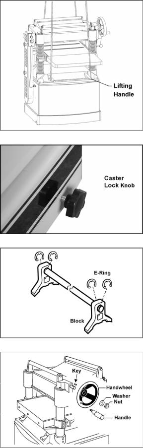
Remove the screws holding the planer to the pallet and use a forklift or hoist to lift the planer off the pallet. Forks and straps should always be placed under the four lifting handles when lifting this machine (Figure 5). The lifting handles can be pushed back in when not in use.
The planer should be operated in a well-lit area with a sturdy floor and good ventilation. It can be rolled on its casters to the desired location. Tighten the lock knob (Figure 6) to prevent movement during operation or adjustments.
Exposed surfaces, such as tables, rollers, cutterhead, etc., have been given a protective coating at the factory. This should be removed with a soft cloth moistened with a good commercial solvent. Do not use acetone, gasoline, lacquer thinner, or other solvents with a low flash point. Do not use an abrasive pad because it may scratch the polished cast iron surfaces.
 Use care when cleaning around the cutterhead area – knives are extremely sharp!
Knife Gauge (model 209 only)
Place the two gauge blocks on the ends of the shaft (Figure 7) and use a pliers to press the four e-rings into the grooves on each side of the blocks.
Handwheel
1.Remove the nut and washer from the gearbox shaft, and place the handwheel onto the shaft (Figure 8), making sure it is oriented so the handwheel slips over the key.
2.Place flat washer and hex nut on shaft and tighten with 19mm wrench.
3.Mount the handle into the threaded hole in the handwheel, and tighten with a 12mm wrench placed over the flat on the handle.
Figure 5
Figure 6
Figure 7 – Model 209 only
Figure 8
9
Extension Tables
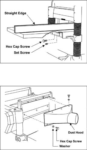
1.Mount a cast iron table to the edge of the main table with three M8 x 25 hex cap screws (Figure 9) using a 12mm wrench. Do not fully tighten yet.
2.The extension table must be leveled with the main table. Place a straight edge (such as a jointed board) across both tables.
3.Insert three socket set screws with a 4mm hex wrench, and screw them in or out as needed until tables are level.
4.Securely tighten the hex cap screws.
5.Mount the second extension table to the opposite side of the planer table, using the same procedure.
Dust Hood
Mount the hood to the rear of the head casting with six M6 x 12 hex cap screws and six 1/4" flat washers (Figure 10), with a 10mm wrench.
It is recommended that you use a dust collection system with this planer. If you are not using a dust collection system, do not attach the dust hood to the planer, as the accumulation of dust inside the hood may create a safety hazard, or eventually cause jamming of the rollers.
Electrical Connections
 Electrical connections must be made by a qualified electrician in compliance with all relevant codes. The machine must be properly grounded to help prevent electrical shock and possible fatal injury.
A power plug is not provided with the 209 planer. You may either connect one or "hardwire" the machine directly to your electrical panel provided there is a disconnect near the machine. Consult electrical schematics on pages 35-37 for further clarification of wiring setup.
This machine must be grounded. Grounding provides a path of least resistance to help divert current away from the operator in case of electrical malfunction.
Make sure the voltage of your power supply matches the specifications on the motor plate of the machine.
Figure 9
Figure 10
10
Extension Cords
The use of an extension cord is not recommended for this machine, but if one proves necessary make sure the cord rating is suitable for the amperage listed on the machine's motor plate. An undersize cord will cause a drop in line voltage resulting in loss of power and overheating.
The chart in Figure 11 shows the correct size cord to use based on cord length and motor plate amp rating. If in doubt, use the next heavier gauge. The smaller the gauge number the heavier the cord.
Adjustments
Tools required for adjustments:
3, 5, 6, and 10mm hex wrenches
12, 14 and 19mm open-end wrenches Feeler gauges
Straight edge
Gauge block or dial gauge Cross-point (Phillips) screwdriver
 Disconnect machine from power source before making any adjustments (except feed rate).
Belt Tension
Inspect the tension of the belts frequently during the first few times you use the planer. Belts often stretch during this trial period. If they require tightening, proceed as follows:
1.Remove the belt guard and the rear panel.
2.Loosen the bottom nuts on the motor adjustment screws (Figure 12) with a 19mm wrench.
3.Turn the top nuts to lower the motor plate, which will increase the belt tension.
4.Proper tension is achieved when there is slight deflection in the belt midway between the pulleys, using moderate finger pressure.
5.Tighten the bottom nuts (Figure 12).
Table Rollers
Your planer is supplied with two table rollers (Figure 13) which turn as the stock is fed into the machine, thus reducing friction. It is not possible to give exact dimensions on the proper height setting of the table rollers because each type of wood behaves differently. As a general rule, however, when planing rough stock the table rollers should be set at high position.
Recommended Gauges (AWG) of Extension Cords
|
|
Extension Cord Length * |
|
|||
|
|
|
|
|
|
|
Amps |
25 |
50 |
75 |
100 |
150 |
200 |
feet |
feet |
feet |
feet |
feet |
feet |
|
|
|
|
|
|
|
|
< 5 |
16 |
16 |
16 |
14 |
12 |
12 |
|
|
|
|
|
|
|
5 to 8 |
16 |
16 |
14 |
12 |
10 |
NR |
|
|
|
|
|
|
|
8 to 12 |
14 |
14 |
12 |
10 |
NR |
NR |
|
|
|
|
|
|
|
12 to 15 |
12 |
12 |
10 |
10 |
NR |
NR |
|
|
|
|
|
|
|
15 to 20 |
10 |
10 |
10 |
NR |
NR |
NR |
|
|
|
|
|
|
|
21 to 30 |
10 |
NR |
NR |
NR |
NR |
NR |
|
|
|
|
|
|
|
*based on limiting the line voltage drop to 5V at 150% of the rated amperes.
NR: Not Recommended.
Figure 11
Figure 12
Figure 13
11
When planing smooth stock the rollers should be set at low position.
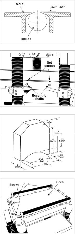
NOTE: When raising the roller higher above the table, the range is from .003" to .006" (Figure 14).
The table rollers are factory set for average planing and are parallel to the table surface. If you desire to adjust the table rollers higher or lower, proceed as follows:
1.Disconnect machine from power source.
2.Lay a straight edge across both rollers.
3.On one side of the table, loosen the set screws (Figure 15) with a 3mm hex wrench, and turn the eccentric shafts to raise or lower the rollers.
4.When proper height is achieved, tighten set screws.
5.Adjust the rollers from the opposite side of the table in the same manner.
IMPORTANT: Be sure that the height of front and rear rollers are the same. The table rollers must always be set parallel to the table.
Cutterhead
Although your planer was carefully adjusted at the factory, it should be checked before being put into operation. Any inaccuracies due to rough handling in transit can be corrected by following the directions in this manual.
To check the adjustments you will need a knifesetting gauge (provided), feeler gauges, and a dial gauge or home-made gauge block made of hardwood. This gauge block can be made by following the dimensions shown in Figure 16. You will also need to remove the belt guard, so you can rotate the cutterhead using the pulley.
Knife Adjustments (Model 209 only)
When checking or adjusting cutterhead knives on the model 209 Planer, proceed as follows:
1.Disconnect machine from power source.
2.Remove the six screws and upper cover (Figure 17).
3.To check and adjust knives, use the provided knife setting gauge and check all four knives. Knives should just contact the bottom of the center protrusion (D, Figure 18) of the knife gauge. Make sure the feet of the knife gauge sit solidly upon the cutterhead, and that its shaft is parallel to the cutterhead (see Figure 19).
Figure 14
Figure 15
Figure 16
Figure 17
12
Loading...