


 Loading...
Operating Instructions and Parts Manual
Woodturning Lathe
Model 3520B
shown with optional 18-inch bed extension and user-made shelf
WMH TOOL GROUP |
|
2420 Vantage Drive |
Part No. M-1352001 |
Elgin, Illinois 60124 |
|
Ph.: 800-274-6848 |
Revision A1 8/06 |
www.wmhtoolgroup.com |
Copyright © WMH Tool Group |

Warranty and Service
WMH Tool Group, Inc., warrants every product it sells. If one of our tools needs service or repair, one of our Authorized Service Center located throughout the United States can give you quick service. In most cases, any of these WMH Tool Group Authorized Service Centers can authorize warranty repair, assist you in obtaining parts, or perform routine maintenance and major repair on your POWERMATIC® tools. For the name of an Authorized Service Center in your area call 1-800-274-6848.
MORE INFORMATION
WMH Tool Group is consistently adding new products to the line. For complete, up-to-date product information, check with your local WMH Tool Group distributor, or visit powermatic.com.
WARRANTY
POWERMATIC products carry a limited warranty which varies in duration based upon the product.
WHAT IS COVERED?
This warranty covers any defects in workmanship or materials subject to the exceptions stated below. Cutting tools, abrasives and other consumables are excluded from warranty coverage.
WHO IS COVERED?
This warranty covers only the initial purchaser of the product.
WHAT IS THE PERIOD OF COVERAGE?
The general POWERMATIC warranty lasts for the time period specified in the product literature of each product.
WHAT IS NOT COVERED?
The Five Year Warranty does not cover products used for commercial, industrial or educational purposes. Products with a Five Year Warranty that are used for commercial, industrial or education purposes revert to a One Year Warranty. This warranty does not cover defects due directly or indirectly to misuse, abuse, negligence or accidents, normal wear-and-tear, improper repair or alterations, or lack of maintenance.
HOW TO GET SERVICE
The product or part must be returned for examination, postage prepaid, to a location designated by us. For the name of the location nearest you, please call 1-800-274-6848.
You must provide proof of initial purchase date and an explanation of the complaint must accompany the merchandise. If our inspection discloses a defect, we will repair or replace the product, or refund the purchase price, at our option.
We will return the repaired product or replacement at our expense unless it is determined by us that there is no defect, or that the defect resulted from causes not within the scope of our warranty in which case we will, at your direction, dispose of or return the product. In the event you choose to have the product returned, you will be responsible for the handling and shipping costs of the return.
HOW STATE LAW APPLIES
This warranty gives you specific legal rights; you may also have other rights which vary from state to state.
LIMITATIONS ON THIS WARRANTY
WMH TOOL GROUP LIMITS ALL IMPLIED WARRANTIES TO THE PERIOD OF THE LIMITED WARRANTY FOR EACH PRODUCT. EXCEPT AS STATED HEREIN, ANY IMPLIED WARRANTIES OR MERCHANTABILITY AND FITNESS ARE EXCLUDED. SOME STATES DO NOT ALLOW LIMITATIONS ON HOW LONG THE IMPLIED WARRANTY LASTS, SO THE ABOVE LIMITATION MAY NOT APPLY TO YOU.
WMH TOOL GROUP SHALL IN NO EVENT BE LIABLE FOR DEATH, INJURIES TO PERSONS OR PROPERTY, OR FOR INCIDENTAL, CONTINGENT, SPECIAL, OR CONSEQUENTIAL DAMAGES ARISING FROM THE USE OF OUR PRODUCTS. SOME STATES DO NOT ALLOW THE EXCLUSION OR LIMITATION OF INCIDENTAL OR CONSEQUENTIAL DAMAGES, SO THE ABOVE LIMITATION OR EXCLUSION MAY NOT APPLY TO YOU.
WMH Tool Group sells through distributors only. The specifications in WMH catalogs are given as general information and are not binding. Members of WMH Tool Group reserve the right to effect at any time, without prior notice, those alterations to parts, fittings, and accessory equipment which they may deem necessary for any reason whatsoever.
2
Table of Contents |
|
Warranty and Service .............................................................................................................................. |
2 |
Table of Contents .................................................................................................................................... |
3 |
Warning................................................................................................................................................... |
4 |
Introduction.............................................................................................................................................. |
6 |
Specifications .......................................................................................................................................... |
6 |
Unpacking ............................................................................................................................................... |
7 |
Contents of the Shipping Container ...................................................................................................... |
7 |
Assembly................................................................................................................................................. |
8 |
Comparator Rear Bracket..................................................................................................................... |
9 |
Tool Caddy........................................................................................................................................... |
9 |
Guard................................................................................................................................................... |
9 |
Bed Extension (Optional Accessory)................................................................................................... |
10 |
Shelf Assemblies (Optional) ............................................................................................................... |
11 |
Grounding Instructions........................................................................................................................... |
12 |
Single Phase Operation...................................................................................................................... |
13 |
Three Phase Operation ...................................................................................................................... |
13 |
Extension cords.................................................................................................................................. |
13 |
Adjustments........................................................................................................................................... |
13 |
Headstock and Tailstock Movement ................................................................................................... |
13 |
Cam Tightness................................................................................................................................... |
14 |
Tool Support ...................................................................................................................................... |
14 |
Locking Handles................................................................................................................................. |
14 |
Live Center and Cone......................................................................................................................... |
15 |
Indexer............................................................................................................................................... |
15 |
Centers – Installing and Removing ..................................................................................................... |
15 |
Face Plate – Installing and Removing................................................................................................. |
16 |
Comparator – Installing and Using...................................................................................................... |
16 |
Speed Change ................................................................................................................................... |
17 |
Sheave and Belt Alignment ................................................................................................................ |
18 |
Checking Spindle Play........................................................................................................................ |
18 |
Sheave/Drive Belt Replacement ......................................................................................................... |
18 |
Operating Controls................................................................................................................................. |
19 |
Operation............................................................................................................................................... |
20 |
Turning Tools..................................................................................................................................... |
21 |
Spindle Turning.................................................................................................................................. |
22 |
Cutting Techniques ............................................................................................................................ |
23 |
Face Plate and Bowl Turning.............................................................................................................. |
25 |
Bowl Turning Techniques ................................................................................................................... |
26 |
Maintenance.......................................................................................................................................... |
27 |
Indexer Positions ................................................................................................................................... |
28 |
Troubleshooting..................................................................................................................................... |
29 |
Recommended Lathe Speeds (per diameter of workpiece)..................................................................... |
30 |
Replacement Parts ................................................................................................................................ |
30 |
Headstock Assembly.......................................................................................................................... |
31 |
Parts List: Headstock Assembly ......................................................................................................... |
32 |
Stand and Bed Assembly ................................................................................................................... |
34 |
Parts List: Stand and Bed Assembly................................................................................................... |
35 |
Optional Accessories: Bed Extensions................................................................................................ |
36 |
Optional Accessories: Outboard Turning Stand................................................................................... |
37 |
Optional Accessories: Adapters, Face Plates, and Tool Supports ....................................................... |
38 |
Optional Accessories: Dust Port Assembly ......................................................................................... |
39 |
Electrical Connections ........................................................................................................................... |
40 |
Electrical: Remote ON/OFF Switch (Optional Accessory) ....................................................................... |
41 |
3

1.Read and understand the entire owners manual before attempting assembly or operation.
2.Read and understand the warnings posted on the machine and in this manual. Failure to comply with all of these warnings may cause serious injury.
3.Replace the warning labels if they become obscured or removed.
4.This Lathe is designed and intended for use by properly trained and experienced personnel only. If you are not familiar with the proper and safe operation of a Lathe, do not use until proper training and knowledge have been obtained.
5.Do not use this Lathe for other than its intended use. If used for other purposes, WMH Tool Group disclaims any real or implied warranty and holds itself harmless from any injury that may result from that use.
6.Always wear approved safety glasses/face shields while using this machine. Everyday eyeglasses only have impact resistant lenses; they are not safety glasses.
7.Before operating this Lathe, remove tie, rings, watches and other jewelry, and roll sleeves up past the elbows. Remove all loose clothing and confine long hair. Non-slip footwear or anti-skid floor strips are recommended. Do not wear gloves.
8.Wear ear protectors (plugs or muffs) during extended periods of operation.
9.Some dust created by power sanding, sawing, grinding, drilling and other construction activities contain chemicals known to cause cancer, birth defects or other reproductive harm. Some examples of these chemicals are:
•Lead from lead based paint.
•Crystalline silica from bricks, cement and other masonry products.
•Arsenic and chromium from chemically treated lumber.
Your risk of exposure varies, depending on how often you do this type of work. To reduce your exposure to these chemicals, work in a well-ventilated area and work with approved safety equipment, such as face or dust masks that are specifically designed to filter out microscopic particles.
10.Do not operate this machine while tired or under the influence of drugs, alcohol or any medication.
11.Do not expose this machine to rain, or operate machine in damp locations.
12.Make certain the switch is in the OFF position before connecting the machine to the power supply.
13.Make certain the machine is properly grounded.
14.Make all machine adjustments or maintenance with the machine unplugged from the power source.
15.Remove adjusting keys and wrenches. Form a habit of checking to see that keys and adjusting wrenches are removed from the machine before turning it on.
16.Keep the safety guard in place at all times when the machine is in use. If removed for maintenance purposes or for turning procedures which do not permit its use, exercise extreme caution and replace the guard immediately after the operation is complete.
17.Check damaged parts. Before further use of the machine, a guard or other part that is damaged should be carefully checked to determine that it will operate properly and perform its intended function. Check for alignment of moving parts, binding of moving parts, breakage of parts, mounting and any other conditions that may affect its operation. A guard or other part that is damaged should be properly repaired or replaced.
18.Provide for adequate space surrounding work area and non-glare, overhead lighting.
19.Keep the floor around the machine clean and free of scrap material, oil and grease.
20.Keep visitors a safe distance from the work area. Keep children away.
21.Make your workshop child proof with padlocks, master switches or by removing starter keys.
4

22.Give your work undivided attention. Looking around, carrying on a conversation and “horse-play” are careless acts that can result in serious injury.
23.Maintain a balanced stance at all times so that you do not fall or lean against the centers, workpiece or other moving parts. Do not overreach or use excessive force to perform any machine operation.
24.Use the right tool at the correct speed and feed rate. Do not force a tool or attachment to do a job for which it was not designed. The right tool will do the job better and safer.
25.Use recommended accessories; improper accessories may be hazardous.
26.Keep turning tools sharp and clean for the best and safest performance, and position the tools properly in relation to the workpiece.
27.Turn off the machine before cleaning. Use a brush or compressed air to remove chips or debris — do not use your hands.
28.Do not stand on the machine. Serious injury could occur if the machine tips over.
29.Never leave the Lathe running unattended. Turn the power off and do not leave the machine until it comes to a complete stop.
30.Remove loose items and unnecessary work pieces from the area before starting the machine.
31.Check the workpiece carefully for splits, knots or other obstructions which may cause a safety risk while turning.
32.Adjust the tool support to the proper height and position for the work. Rotate the workpiece by hand to check clearance with the tool support.
33.Select the appropriate speed for the turning job at hand. Start at low speed and allow the Lathe to ramp up to operating speed.
34.Never stop a rotating workpiece with your hand.
35.If gluing up a workpiece, always use a high-quality glue of the type necessary for that particular workpiece.
Familiarize yourself with the following safety notices used in this manual:
 This means that if precautions are not heeded, it may result in minor injury and/or possible machine damage.
 This means that if precautions are not heeded, it may result in serious injury or possibly even death.
- - SAVE THESE INSTRUCTIONS - -
5
Introduction
This manual is provided by WMH Tool Group covering the safe operation and maintenance procedures for a Model 3520B Lathe. This manual contains instructions on installation, safety precautions, general operating procedures, maintenance instructions and parts breakdown. This machine has been designed and constructed to provide years of trouble free operation if used in accordance with instructions set forth in this manual. If there are any questions or comments, please contact either your local supplier or WMH Tool Group. WMH Tool Group can also be reached at our web site: www.wmhtoolgroup.com.
Specifications |
|
Model Number................................................................................................................................. |
3520B |
Stock Number.............................................................................................................................. |
1352001 |
Working distance between centers (in.)............................................................................................ |
31-1/2 |
Working distance between centers, 18” bed extension mounted (in.)...................................................... |
48 |
Maximum distance between spindle face and tailstock quill (in.)............................................................. |
36 |
Swing over bed (in.)............................................................................................................................... |
20 |
Maximum overall length (in.) .................................................................................................................. |
73 |
Overall height to top of headstock (in.) ............................................................................................. |
49-1/2 |
Distance from floor to centerline of spindle (in.)...................................................................................... |
45 |
Spindle speeds (RPM) .................................................................................... |
high 125-3200; low 50-1200 |
Motor................................................................................................................... |
TEFC, 2HP, 220V, 60Hz |
Lathe power requirements ............................................................................................. |
220V, 3Ph or 1Ph |
Spindle thread size (in.) ........................................................................................................ |
1-1/4 x 8 TPI. |
Headstock spindle taper.............................................................................................................. |
#2 Morse |
Tailstock quill taper ..................................................................................................................... |
#2 Morse |
Hole through tailstock spindle, diameter (in.)......................................................................................... |
3/8 |
Hole through headstock spindle, diameter (in.)...................................................................................... |
5/8 |
Drive system....................................................................................................... |
Poly V belt, inverter drive |
Tailstock quill travel (in.)..................................................................................................................... |
4-1/2 |
Footprint of stand (in.)............................................................................................................. |
50 L x 24 W |
Spindle direction ................................................................................................................ |
forward/reverse |
Net Weight (lbs.).................................................................................................................................. |
630 |
Shipping Weight (lbs.).......................................................................................................................... |
682 |
The above specifications were current at the time this manual was published, but because of our policy of continuous improvement, WMH Tool Group reserves the right to change specifications at any time and without prior notice, without incurring obligations.
6

Unpacking
Open shipping container and check for shipping damage. Report any damage immediately to your distributor and shipping agent. Do not discard any shipping material until the Lathe is assembled and running properly.
Compare the contents of your container with the following parts list to make sure all parts are intact. Some parts can be found in separate boxes packed around the Lathe. Missing parts, if any, should be reported to your distributor. Read the instruction manual thoroughly for assembly, maintenance and safety instructions.
Contents of the Shipping Container
1Lathe Bed, with Headstock, Tailstock, & Tool Support Base – (A)
2Leg Assemblies – (B)
1 Guard – (C)
1Tool Support, 14” – (D)
1Face Plate, 3” – (E)
1Live Center – (F)
1Spur Center, 1” – (G)
1Index Pin – (H)
1Live Center Pin – (J)
1Knockout Rod – (K)
1Face Plate Wrench – (L)
1Tool Caddy – (M)
4Levelers – (N)
12Socket Hd. Cap Screws, 3/8” x 1-1/4” – (O)
12Lock Washers, 3/8” – (P)
10Flat Washers, 3/8” – (R)
2Comparator Centers – (S)
1Comparator Rear Bracket with Lock Handle – (T)
1 Owner's Manual
1 Warranty Card
Read and understand the entire contents of this manual before attempting set-up or operation! Failure to comply may cause serious injury.
7
Assembly
Tools required for assembly
Forklift or hoist with straps/slings 14mm wrench
4mm and 8mm hex wrenches
 The Lathe should be disconnected from power during assembly.
1.Remove any screws or straps that hold the Lathe parts to the pallet, and remove protective wrapping.
2.The Lathe should be located in a dry area, on a sturdy floor, and with sufficient lighting. Leave plenty of space around the machine for operations and routine maintenance work.
If you have a hoist or forklift:
3.Lift the Lathe off the pallet using a forklift or hoist, and move it to the desired location. (Forks may need to be positioned more toward the headstock to balance the weight.) Proceed to step 6 to install the legs and levelers while the Lathe is still off the floor.
If you do NOT have a hoist or forklift:
4.If a forklift or hoist is not available, the use of one or more assistants is mandatory. First decrease the weight on the Lathe by removing the headstock, tailstock and tool support base (Refer to “Headstock and Tailstock Movement” on page 13 for removal instructions).
 The headstock is heavy; use caution when removing it from the lathe bed.
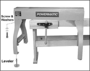
5.Lift the Lathe bed and set it upside down on the floor (make sure padding/cloths have been laid down to prevent scratching the bed). Or, set the Lathe bed upon a table of sufficient height to allow the legs and levelers to be assembled, as shown in Figure 1.
6.While the Lathe is off the floor, install the legs to the bed using eight socket head cap screws with eight lock washers and eight flat washers (Figure 1). Tighten the screws firmly with a 8mm hex wrench.
7.Screw the levelers into the threaded holes of the legs (Figure 1). Tighten the hex nuts against the bottom of the legs with a 14mm wrench.
Figure 1
8
8.The levelers can be adjusted at any time to ensure the Lathe is stable and level.
9.Set the Lathe right side up (or remove it from the table).
10.Exposed metal areas of the Lathe, such as the bed and spindles, have been factory coated with a protectant. This should be removed with a soft cloth and a cleanerdegreaser. Clean the bed areas under the headstock, tailstock and tool support base. Do not use an abrasive pad, and do not allow solvents to contact painted or plastic areas.
11.Re-install headstock, tool support base, and tailstock.
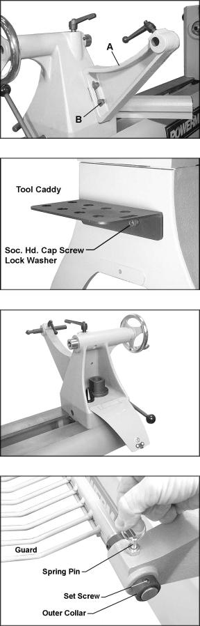
Comparator Rear Bracket
Mount the comparator rear bracket (A, Figure 2) to the back of the tailstock with two 3/8 x 1-1/4 socket head cap screws, two 3/8 lock washers and two 3/8 flat washers (B, Figure 2). The bracket has a slot so it can be aligned with the bracket on the headstock. (See “Comparator – Installing and Using” for further information.)
Tool Caddy
The tool caddy, shown in Figure 3, can be mounted to the left end or right end of the Lathe. The left end, near the headstock area, is generally preferred for convenience. Use two socket head cap screws and two lock washers with an 8mm hex wrench to secure the tool caddy to the threaded holes in the Lathe.
The tool caddy has holes for placing the knockout rod, spur center, live center, live center pin, comparator centers, and faceplate wrench.
Accessories can also be stored in the tailstock, as shown in Figure 4.
Guard
 The guard must always be used in operations that will allow its use.
1.On the guard, loosen the set screw on the outer collar (shown in Figure 5) with a 4mm hex wrench. Slide the outer collar off the guard support rod.
2.Insert the guard support rod into the mounting bracket at the rear of the headstock, as shown in Figure 5. You will have to lift up on the spring pin, as shown, to slide the guard support rod into the mounting bracket. Release the spring pin and it will snap into position as you slide the support rod farther in.
Figure 2
Figure 3
Figure 4
Figure 5
9
3.Install the outer collar and tighten the set screw.
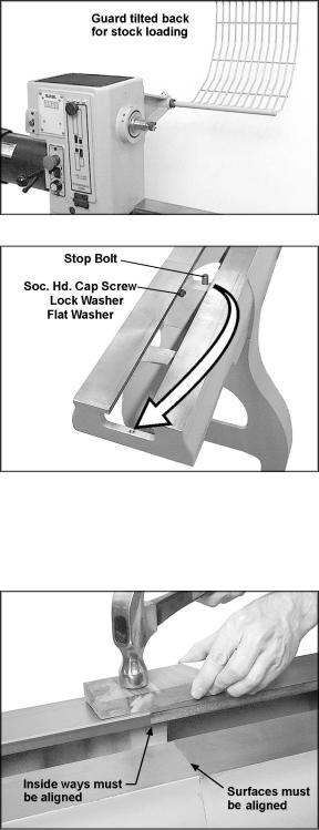
4.The guard can be pivoted to one of two positions: Operating mode (shown on front cover) or tilted back for stock loading (shown in Figure 6).
5.Pull up on the spring pin, and begin tilting the guard, then release the spring pin. When the guard reaches either of the two positions, the spring pin will engage.
Bed Extension (Optional Accessory)
An optional 18” bed extension assembly, stock number 6294727B, is available for the Lathe (see your Powermatic dealer). To mount the bed extension to the Lathe:
1.Slide the tailstock away from the edge of the bed.
2.Have an assistant hold the bed extension flush to the end of the Lathe bed, and insert three 3/8 x 1-3/4 socket head cap screws, three 3/8 lock washers and three 3/8 flat washers, through the holes in the bed extension into the threaded holes on the Lathe. See Figure 7.
3.Shift the bed extension upward so that it is slightly higher than the Lathe bed. Tighten the screws with an 8mm wrench just enough to hold the bed extension to the Lathe bed.
IMPORTANT: The surface of the bed extension must be level with the surface of the Lathe bed to allow smooth movement of the tailstock across the seam.
4.Use a dead blow mallet, or a hammer with a block of wood, to tap down the bed extension until it is flush with the Lathe bed. See Figure 8. Never use a steel-faced hammer directly against the bed surfaces. Tap the bed extension where needed until its surface is aligned with the Lathe bed, and the inside ways are aligned.
5.Firmly tighten the three socket head cap screws. Make sure your alignment of the bed surfaces doesn’t shift while tightening the screws.
6.Unscrew the stop bolt from the Lathe bed (Figure 7), and screw it into the hole at the end of the bed extension.
Figure 6
Figure 7
(optional 18” bed extension shown)
Figure 8
10
For outboard turning, where the headstock is moved to the opposite end of the Lathe to accommodate large bowl blanks, you can (1) mount the 18” bed extension to the three lower holes on the Lathe frame, and (2) mount a vertical extension post [optional accessory, stock number 3520B-310] to the tool rest base. See Figure 9.
Shelf Assemblies (Optional)
The double ledges on the inside of the Lathe legs will provide support for a shelf (not provided), which is convenient for storing larger items while keeping them easily accessible.
Figures 10-11-12 illustrate three methods of creating a shelf, using common lumber and basic tools.
IMPORTANT TIP: It is unlikely that a full-size shelf can be completely built and then inserted between the Lathe legs. Therefore, construct the shelf in pieces and insert screws only after the shelf has been established beneath the Lathe.
Shelf Style 1 (Figure 10)
Lay two 2x6 boards flat upon the inner ledges. Boards of 48” length are suitable, although 48- 1/2” is optimal.
Shelf Style 2 (Figure 11)
Lay two 2x4’s (or 2x6’s) on edge into the outer ledges. Boards of 48” length are suitable, 48- 1/2” optimal.
Cut two pieces from a plywood board, and screw them to the top edges of the 2x4’s. (One 48” plywood piece will not fit through the legs of the Lathe; use at least two pieces.) Make the plywood pieces flush with the outside edge of the 2x4’s.
Shelf Style 3: (Figure 12)
This is a basket-style shelf consisting of two 2x6’s and dowel rods. The advantage of this design is that most wood chips will fall through the shelf instead of accumulating on it. The instructions below are for building the shelf shown in Figure 12. The completed shelf is shown on the front cover of this manual.
Materials used:
2 – 2x6’s (48” suitable, 48-1/2” optimal).
8 – wood dowels, 4’ length, 5/8” diameter.
11
Figure 9
(shown with optional accessories)
Figure 10
Figure 11

1.Mark your hole centers (2” centers) along the length of a 2x6. Place the holes so that the tops of the dowels will be even with the tops of the ledges on the Lathe. Also, adjust your hole centers as necessary so that the first and last dowel will begin at approximately the same distance from the ledge at both ends of the Lathe.
2.Use a 5/8” spade bit chucked in a drill press or in a portable drill. Bore the holes through one 2x6; this will be the rear piece.
3.On the other 2x6, do not bore through but only deep enough to securely hold the ends
of the dowel rods. This will be the front |
Figure 12 |
|
piece and will provide a pleasing |
||
|
||
appearance at the front of your Lathe. |
|
4.When all holes have been bored, place the 2x6’s on edge in the outer ledges of the Lathe.
5.Cut the dowel rods to length with a miter saw or hand saw, so that after insertion the rods will be flush with the back of the rear 2x6.
6.Insert the dowel rods through the holes in the rear 2x6, as shown in Figure 12.
7.A strip of wood can be screwed to the rear 2x6 to cover the dowel holes and prevent the dowels from working out.
Grounding Instructions
 Electrical connections must be made by a qualified electrician in compliance with all relevant codes. This machine must be properly grounded to help prevent electrical shock and possible fatal injury.
This machine must be grounded. In the event of a malfunction or breakdown, grounding provides a path of least resistance for electric current to reduce the risk of electric shock.
Improper connection of the equipmentgrounding conductor can result in a risk of electric shock. The conductor, with insulation having an outer surface that is green with or without yellow stripes, is the equipmentgrounding conductor. If repair or replacement of the electric cord or plug is necessary, do not connect the equipment-grounding conductor to a live terminal.
Check with a qualified electrician or service personnel if the grounding instructions are not completely understood, or if in doubt as to whether the tool is properly grounded.
12
Repair or replace a damaged or worn cord immediately.
The Lathe will operate on single phase or three phase, 230 volt power supply. The Lathe should be connected to a dedicated circuit. Make sure the characteristics of your power supply match the specifications on the motor plate of the Lathe.
Single Phase Operation
A three wire pigtail for use on 230 volt single phase power is attached to the inverter and may be “hard-wired” to the power source, or connected to a UL/CSA listed receptacle plug.
Connect the 230 volt supply to the black and white leads and ground the green lead.
If you are hard-wiring the Lathe to a panel, make sure a disconnect is available for the operator. During hard-wiring of the Lathe, make sure the fuses have been removed or the breakers have been tripped in the circuit to which the Lathe will be connected. Place a warning placard on the fuse holder or circuit breaker to prevent it being turned on while the machine is being wired.
Three Phase Operation
If three phase power is used, it will be necessary to replace the pigtail wire attached to the inverter with a 12/4 wire and connect the three hot leads to the inverter at R, S, T as shown in the wiring diagram on page 40. Always connect the ground lead.
Extension cords
If an extension cord is necessary, make sure the cord rating is suitable for the amperage listed on the machine’s motor plate. An undersized cord will cause a drop in line voltage resulting in loss of power and overheating.
Use the chart in Figure 13 as a general guide in choosing the correct size cord. If in doubt, use the next heavier gauge. The smaller the gauge number, the heavier the cord.
Adjustments
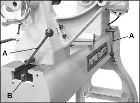
Headstock and Tailstock Movement
To slide the headstock or tailstock, swing the locking handle (A, Figure 14) backward or forward until the headstock/tailstock can slide freely. When the headstock/tailstock is positioned, rotate the locking handle to tighten it securely.
Recommended Gauges (AWG) of Extension Cords
|
|
Extension Cord Length * |
|
|||
|
|
|
|
|
|
|
Amps |
25 |
50 |
75 |
100 |
150 |
200 |
feet |
feet |
feet |
feet |
feet |
feet |
|
|
|
|
|
|
|
|
< 5 |
16 |
16 |
16 |
14 |
12 |
12 |
|
|
|
|
|
|
|
5 to 8 |
16 |
16 |
14 |
12 |
10 |
NR |
|
|
|
|
|
|
|
8 to 12 |
14 |
14 |
12 |
10 |
NR |
NR |
|
|
|
|
|
|
|
12 to 15 |
12 |
12 |
10 |
10 |
NR |
NR |
|
|
|
|
|
|
|
15 to 20 |
10 |
10 |
10 |
NR |
NR |
NR |
|
|
|
|
|
|
|
21 to 30 |
10 |
NR |
NR |
NR |
NR |
NR |
|
|
|
|
|
|
|
*based on limiting the line voltage drop to 5V at 150% of the rated amperes.
NR: Not Recommended.
Figure 13
Figure 14
13
To remove headstock, tailstock or toolrest base from the bed, unscrew and remove either of the stop bolts (B, Figure 14). After re-mounting these items on the Lathe, re-insert the stop bolt.
For most turning operations, except outboard turning, the headstock should be positioned at the left end of the bed, and only the tailstock moved to accomodate the workpiece.
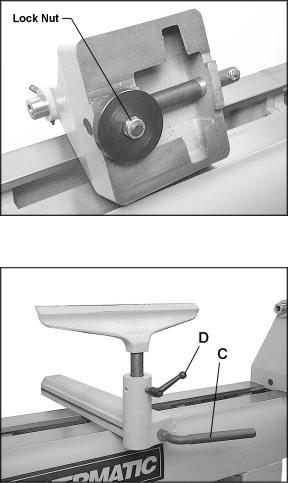
Cam Tightness
If the headstock, tailstock or tool rest base does not tighten properly down against the Lathe bed when the locking handle is tightened, it may need adjusting. Figure 15 uses the tailstock as the example:
1.Unscrew and remove the stop bolt on the end of the lathe bed (B, Figure 14) and slide the tailstock off the end of the bed.
2.Turn the tailstock on its side, and tighten the lock nut with a wrench. See Figure 15.
3.Mount tailstock on bed and insert the stop bolt.
Tool Support
A 14” tool support is provided with your Lathe. It is designed to allow adjustment for height, position on the bed, and angle to the work.
Loosen the locking handle on the tool support base (C, Figure 16) to slide the support base forward or back, and to angle it to the bed. Tighten the locking handle firmly before operating the Lathe.
Loosen the small handle (D, Figure 16) to raise or lower the tool support and angle it to the work. Tighten the handle before operating the Lathe.
The small handle (D, Figure 16) can be inserted into one of three holes on the tool support base. The position shown in Figure 16 is preferred so that the locking handle contacts the groove in the tool rest shaft.
Locking Handles
Each small locking handle such as D, Figure 16 can be rotated to a more convenient position. Simply lift up on the handle, rotate it on the pin, then release it, making sure it seats itself on the pin.
Figure 15
Figure 16
14
Loading...