


 Loading...
Operating Instructions and Parts Manual
Tilting Table Hollow Chisel Mortiser
Model: 719T
Powermatic |
|
427 New Sanford Road |
Part No. M-2474002 |
LaVergne, Tennessee 37086 |
|
Ph.: 800-274-6848 |
Revision B2 02/2014 |
www.powermatic.com |
Copyright © 2014 Powermatic |

Warranty and Service
Powermatic warrants every product it sells against manufacturers’ defects. If one of our tools needs service or repair, please contact Technical Service by calling 1-800-274-6846, 8AM to 5PM CST, Monday through Friday.
Warranty Period
The general warranty lasts for the time period specified in the literature included with your product or on the official Powermatic branded website.
•Powermatic products carry a limited warranty which varies in duration based upon the product. (See chart below)
•Accessories carry a limited warranty of one year from the date of receipt.
•Consumable items are defined as expendable parts or accessories expected to become inoperable within a reasonable amount of use and are covered by a 90 day limited warranty against manufacturer’s defects.
Who is Covered
This warranty covers only the initial purchaser of the product from the date of delivery.
What is Covered
This warranty covers any defects in workmanship or materials subject to the limitations stated below. This warranty does not cover failures due directly or indirectly to misuse, abuse, negligence or accidents, normal wear-and-tear, improper repair, alterations or lack of maintenance.
Warranty Limitations
Woodworking products with a Five Year Warranty that are used for commercial or industrial purposes default to a Two Year Warranty. Please contact Technical Service at 1-800-274-6846 for further clarification.
How to Get Technical Support
Please contact Technical Service by calling 1-800-274-6846. Please note that you will be asked to provide proof of initial purchase when calling. If a product requires further inspection, the Technical Service representative will explain and assist with any additional action needed. Powermatic has Authorized Service Centers located throughout the United States. For the name of an Authorized Service Center in your area call 1-800-274-6846 or use the Service Center Locator on the Powermatic website.
More Information
Powermatic is constantly adding new products. For complete, up-to-date product information, check with your local distributor or visit the Powermatic website.
How State Law Applies
This warranty gives you specific legal rights, subject to applicable state law.
Limitations on This Warranty
POWERMATIC LIMITS ALL IMPLIED WARRANTIES TO THE PERIOD OF THE LIMITED WARRANTY FOR EACH PRODUCT. EXCEPT AS STATED HEREIN, ANY IMPLIED WARRANTIES OF MERCHANTABILITY AND FITNESS FOR A PARTICULAR PURPOSE ARE EXCLUDED. SOME STATES DO NOT ALLOW LIMITATIONS ON HOW LONG AN IMPLIED WARRANTY LASTS, SO THE ABOVE LIMITATION MAY NOT APPLY TO YOU.
POWERMATIC SHALL IN NO EVENT BE LIABLE FOR DEATH, INJURIES TO PERSONS OR PROPERTY, OR FOR INCIDENTAL, CONTINGENT, SPECIAL, OR CONSEQUENTIAL DAMAGES ARISING FROM THE USE OF OUR PRODUCTS. SOME STATES DO NOT ALLOW THE EXCLUSION OR LIMITATION OF INCIDENTAL OR CONSEQUENTIAL DAMAGES, SO THE ABOVE LIMITATION OR EXCLUSION MAY NOT APPLY TO YOU.
Powermatic sells through distributors only. The specifications listed in Powermatic printed materials and on the official Powermatic website are given as general information and are not binding. Powermatic reserves the right to effect at any time, without prior notice, those alterations to parts, fittings, and accessory equipment which they may deem necessary for any reason whatsoever.
Product Listing with Warranty Period
90 Days – Parts; Consumable items
1 Year – Woodworking Machinery used for industrial or commercial purposes
5 Year – Woodworking Machinery
NOTE: Powermatic is a division of JPW Industries, Inc. References in this document to Powermatic also apply to JPW Industries, Inc., or any of its successors in interest to the Powermatic brand.
2
Table of Contents |
|
Warranty and Service .............................................................................................................................. |
2 |
Table of Contents .................................................................................................................................... |
3 |
Warnings................................................................................................................................................. |
4 |
Introduction ............................................................................................................................................. |
6 |
Specifications .......................................................................................................................................... |
6 |
Unpacking ............................................................................................................................................... |
7 |
Contents of the Mortiser Carton............................................................................................................ |
7 |
Contents of the Stand Carton ............................................................................................................... |
7 |
Electrical Connections ............................................................................................................................. |
8 |
Grounding Instructions ......................................................................................................................... |
8 |
Converting from 115 to 230 Volt ........................................................................................................... |
9 |
Extension Cords................................................................................................................................... |
9 |
Assembly .............................................................................................................................................. |
10 |
Securing Machine to Stand ................................................................................................................ |
10 |
Wooden Table ................................................................................................................................... |
10 |
Operating Handle............................................................................................................................... |
10 |
Installing Chisel and Bit...................................................................................................................... |
11 |
Work Stop.......................................................................................................................................... |
11 |
Operating Controls ................................................................................................................................ |
12 |
Start/Stop Switch ............................................................................................................................... |
12 |
On-Off Switch Padlock........................................................................................................................... |
12 |
Adjustments .......................................................................................................................................... |
13 |
90° Chisel to Worktable Calibration .................................................................................................... |
13 |
Chuck Extension Adaptor................................................................................................................... |
13 |
Depth Stop Rod Adjustment ............................................................................................................... |
14 |
Table Position.................................................................................................................................... |
14 |
Forward/Backward Table Movement............................................................................................... |
14 |
Lateral Table Movement ................................................................................................................. |
14 |
Table Tilt Control ............................................................................................................................ |
14 |
Chisel Parallel to Workpiece............................................................................................................... |
15 |
Operation .............................................................................................................................................. |
15 |
Maintenance.......................................................................................................................................... |
16 |
General.............................................................................................................................................. |
16 |
Sharpening Chisel and Bit.................................................................................................................. |
16 |
Bit................................................................................................................................................... |
16 |
Chisel ............................................................................................................................................. |
17 |
Lubrication ......................................................................................................................................... |
17 |
Storage.............................................................................................................................................. |
17 |
Optional Accessories ............................................................................................................................. |
17 |
Replacement Parts................................................................................................................................ |
17 |
719T Mortiser Assembly..................................................................................................................... |
18 |
719T Mortiser Parts List ..................................................................................................................... |
19 |
719T Mortiser Stand Parts List ........................................................................................................... |
22 |
719T Mortiser Stand Assembly........................................................................................................... |
22 |
Optional Accessories ......................................................................................................................... |
23 |
Dimensions for 719T with premium chisels mounted.............................................................................. |
24 |
3

1.Read and understand the entire owner’s manual before attempting assembly or operation.
2.Read and understand the warnings posted on the machine and in this manual. Failure to comply with all of these warnings may cause serious injury.
3.Replace the warning labels if they become obscured or removed.
4.This mortiser is designed and intended for use by properly trained and experienced personnel only. If you are not familiar with the proper and safe operation of a mortiser, do not use until proper training and knowledge have been obtained.
5.Do not use this mortiser for other than its intended use. If used for other purposes, Powermatic disclaims any real or implied warranty and holds itself harmless from any injury that may result from that use.
6.Always wear approved safety glasses/face shields while using this mortiser. Everyday eyeglasses only have impact resistant lenses; they are NOT safety glasses. Also use a dust mask if cutting operation is dusty.
7.Before operating this mortiser, remove tie, rings, watches and other jewelry, and roll sleeves up past the elbows. Secure all loose clothing and confine long hair. Non-slip footwear or anti-skid floor strips are recommended. Do not wear gloves.
8.Wear ear protectors (plugs or muffs) during extended periods of operation.
9.Some dust created by power sanding, sawing, grinding, drilling and other construction activities contain chemicals known to cause cancer, birth defects or other reproductive harm. Some examples of these chemicals are:
•Lead from lead based paint.
•Crystalline silica from bricks, cement and other masonry products.
•Arsenic and chromium from chemically treated lumber.
Your risk of exposure varies, depending on how often you do this type of work. To reduce your exposure to these chemicals, work in a well-ventilated area and work with approved safety equipment, such as face or dust masks that are specifically designed to filter out microscopic particles.
10.Do not operate this machine while tired or under the influence of drugs, alcohol or any medication.
11.Make certain the switch is in the OFF position before connecting the machine to the power supply.
12.Make certain the machine is properly grounded.
13.Make all machine adjustments or maintenance with the machine unplugged from the power source.
14.Remove adjusting keys and wrenches. Form a habit of checking to see that keys and adjusting wrenches are removed from the machine before turning it on.
15.Keep safety guards in place at all times when the machine is in use. If removed for maintenance purposes, use extreme caution and replace the guards immediately after maintenance is complete.
16.Make sure the mortiser is firmly secured to the stand before use.
17.Check damaged parts. Before further use of the machine, a guard or other part that is damaged should be carefully checked to determine that it will operate properly and perform its intended function. Check for alignment of moving parts, binding of moving parts, breakage of parts, mounting and any other conditions that may affect its operation. A guard or other part that is damaged should be properly repaired or replaced.
18.Provide for adequate space surrounding work area and non-glare, overhead lighting.
19.Keep the floor around the machine clean and free of scrap material, oil and grease.
20.Keep visitors a safe distance from the work area. Keep children away.
4

21.Make your workshop child proof with padlocks, master switches or by removing starter keys.
22.Give your work undivided attention. Looking around, carrying on a conversation and “horse-play” are careless acts that can result in serious injury.
23.Maintain a balanced stance at all times so that you do not fall or lean against the chisel and drill bits or other moving parts. Do not overreach or use excessive force to perform any machine operation.
24.Use the right tool at the correct speed and feed rate. Do not force a tool or attachment to do a job for which it was not designed. The right tool will do the job better and safer.
25.Use recommended accessories; improper accessories may be hazardous.
26.Do not use this tool in damp or wet locations.
27.Maintain tools with care. Keep chisel and drill bits sharp and clean for the best and safest performance. Follow instructions for lubricating and changing accessories.
28.Make sure the work piece is securely attached or clamped to the table. Do not cut mortises freehand.
29.Turn off the machine before cleaning. Use a brush or compressed air to remove chips or debris — do not use your hands.
30.Do not stand on the machine. Serious injury could occur if the machine tips over.
31.Never leave the machine running unattended. Turn the power off and do not leave the machine until it comes to a complete stop.
32.Remove loose items and unnecessary work pieces from the area before starting the machine.
Familiarize yourself with the following safety notices used in this manual:
 This means that if precautions are not heeded, it may result in minor injury and/or possible machine damage.
 This means that if precautions are not heeded, it may result in serious injury or possibly even death.
- - SAVE THESE INSTRUCTIONS - -
5
Introduction
This manual is provided by Powermatic covering the safe operation and maintenance procedures for a Powermatic Model 719T Tilting Table Hollow Chisel Mortiser. This manual contains instructions on installation, safety precautions, general operating procedures, maintenance instructions and parts breakdown. This machine has been designed and constructed to provide years of trouble free operation if used in accordance to instructions set forth in this manual. If there are any questions or comments, please contact either your local supplier or Powermatic. Powermatic can also be reached at our web site: www.powermatic.com.
Specifications
Model No........................................................................................................................................... |
719T |
Stock No. .................................................................................................................................. |
1791264K |
Stock No – Mortiser only............................................................................................................ |
2474002T |
Stock No – Stand only ............................................................................................................... |
6294235T |
Motor..................................................................... |
TEFC, 1 HP, 1 PH, 115V/230V (Prewired 115V), 60Hz |
Spindle speed............................................................................................................................ |
1725 RPM |
Table tilt ...................................................................................................................................... |
0° to 35° |
Chisel capacity ............................................................................................................................ |
1/4" to 1" |
Chisel shank diameters ................................................................................................... |
5/8", 3/4", 1-1/8" |
Maximum chisel stroke ................................................................................................................... |
10-3/4" |
Maximum head stroke ............................................................................................................................ |
6" |
Maximum chisel center to fence distance................................................................................................ |
4" |
Chuck capacity .................................................................................................................................... |
1/2" |
Bushing size..................................................................................................................... |
5/8", 3/4", 1-1/8" |
Longitudinal table travel.................................................................................................................. |
15-1/2" |
Cross table travel.................................................................................................................................... |
4" |
Table size................................................................................................................................ |
7" x 20-1/4" |
Fence size......................................................................................................................... |
4-1/2" x 20-1/4" |
Base size .................................................................................................................................... |
14" x 16" |
Overall dimensions assembled ..................................................................... |
21-1/4" L x 21-5/8" W x 74" H |
Weight - Mortiser ...................................................................... |
Net weight 230 lbs., Gross weight 242 lbs. |
Weight - Stand.............................................................................. |
Net weight 46 lbs., Gross weight 50 lbs. |
The above specifications were current at the time this manual was published, but because of our policy of continuous improvement, Powermatic reserves the right to change specifications at any time and without prior notice, without incurring obligations.
6
Unpacking
Remove mortiser and stand from the shipping cartons. Report any damage immediately to your distributor and shipping agent. Do not discard any shipping material until the mortiser is assembled and running properly.
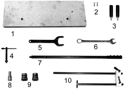
Compare the contents of your container with the following parts list and Figure 1 to make sure all parts are intact. Missing parts, if any, should be reported to your distributor. Read this instruction manual thoroughly to familiarize yourself with the correct assembly and maintenance procedures and proper safety precautions.
Contents of the Mortiser Carton
1 ea – Mortiser (not shown)
1.1 ea – Wooden Table
2.2 ea – M6 x 20 Phillips Head Screws
3.2 ea – Handwheel Handles
4.1 ea – Chuck Key
5.1 ea – Chuck Removal Wrench
6.1 ea – 23mm Box Wrench
7.1 ea – Operating Handle
8.1ea – Chuck Extension Adaptor
9.2 ea – Chisel Bushings (3/4", 1-1/8")
Note: The Mortiser also comes with a 5/8" bushing already installed.
10.1 Work Stop Assembly
Contents of the Stand Carton
1 Stand (not shown)
1Hardware package – (4) M8 x 45 Hex Cap Screws, (4) M8 Lock Washers (not shown)
Contents of the Mortiser Carton
Figure 1
7
Electrical Connections
A separate electrical circuit should be used for your machines. This circuit should not be less than #12 wire and should be protected with a 20 Amp time lag fuse. If an extension cord is used, use only 3-wire extension cords which have 3-prong grounding type plugs and matching receptacle, which will accept the machine’s plug. Before connecting the machine to the power line, make sure the switch is in the Off position and be sure that the electric current is of the same characteristics as indicated on the machine. All line connections should make good contact. Running on low voltage will damage the machine.
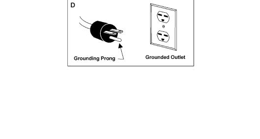
Grounding Instructions
 Electrical connections must be made by a qualified electrician in compliance with all relevant codes. This machine must be properly grounded to help prevent electrical shock and possible fatal injury.
1. All grounded, cord-connected tools:
In the event of a malfunction or breakdown, grounding provides a path of least resistance for electric current to reduce the risk of electric shock. This tool is equipped with an electric cord having an equipment-grounding conductor and a grounding plug. The plug must be plugged into a matching outlet that is properly installed and grounded in accordance with all local codes and ordinances.
Do not modify the plug provided - if it will not fit the outlet, have the proper outlet installed by a qualified electrician.
Improper connection of the equipment-grounding conductor can result in a risk of electric shock. The conductor with insulation having an outer surface that is green with or without yellow stripes is the equipment-grounding conductor. If repair or replacement of the electric cord or plug is necessary, do not connect the equipment-grounding conductor to a live terminal.
Check with a qualified electrician or service personnel if the grounding instructions are not completely understood, or if in doubt as to whether the tool is properly grounded.
Use only 3-wire extension cords that have 3-prong grounding plugs and 3 pole receptacles that accept the tool's plug.
Repair or replace damaged or worn cord immediately.
2. Grounded, cord-connected tools intended for use on a supply circuit having a nominal rating less than 150 volts:
This tool is intended for use on a circuit that has an outlet that looks like the one illustrated in Sketch A in Figure 1. The tool has a grounding plug that looks like the plug illustrated in Sketch A in Figure 1. A temporary adapter, which looks like the adapter illustrated in Sketch B and C, may be used to connect this plug to a 2 pole receptacle as shown in Sketch C if a properly grounded outlet is not available. The temporary adapter should be used only until a properly grounded outlet can be installed by a qualified electrician. This adapter is not permitted in Canada. The greencolored rigid ear, lug, and the like, extending from the adapter must be connected to a permanent ground such as a properly grounded outlet box.
Figure 2
8
Loading...