


20" THICKNESS PLANER
Model 208
Instruction Manual & Parts List
M-0460217
(800) 274-6848 www.powermatic.com

This manual has been prepared for the owner and operators of a Powermatic Model 208 Planer. Its purpose, aside from machine operation, is to promote safety through the use of accepted correct operating and maintenance procedures. Completely read the safety and maintenance instructions before operating or servicing the machine. To obtain maximum life and efficiency from your planer and to aid in using the machine safely, read this manual thoroughly and follow all instructions carefully.
Warranty & Service
The WMH Tool Group warrants every product it sells. If one of our tools needs service or repair, one of our Authorized Repair Stations located throughout the United States can give you quick service.
In most cases, any one of these WMH Tool Group Repair Stations can authorize warranty repair, assist you in obtaining parts, or perform routine maintenance and major repair on your JET, Powermatic, Performax, or Wilton tools.
For the name of an Authorized Repair Station in your area, please call 1-800-274-6848.
More Information
Remember, the WMH Tool Group is consistently adding new products to the line. For complete, up-to-date product information, check with your local WMH Tool Group distributor.
WMH Tool Group Warranty
The WMH Tool Group makes every effort to assure that its products meet high quality and durability standards and warrants to the original retail consumer/purchaser of our products that each product be free from defects in materials and workmanship as follow: 1 YEAR LIMITED WARRANTY ON ALL PRODUCTS UNLESS SPECIFIED OTHERWISE. This Warranty does not apply to defects due directly or indirectly to misuse, abuse, negligence or accidents, normal wear-and-tear, repair or alterations outside our facilities, or to a lack of maintenance.
THE WMH TOOL GROUP LIMITS ALL IMPLIED WARRANTIES TO THE PERIOD SPECIFIED ABOVE, FROM THE DATE THE PRODUCT WAS PURCHASED AT RETAIL. EXCEPT AS STATED HEREIN, ANY IMPLIED WARRANTIES OR MERCHANTIBILITY AND FITNESS ARE EXCLUDED. SOME STATES DO NOT
ALLOW LIMITATIONS ON HOW LONG THE IMPLIED WARRANTY LASTS, SO THE ABOVE LIMITATION MAY NOT APPLY TO YOU. THE WMH TOOL GROUP SHALL IN NO EVENT BE LIABLE FOR DEATH, INJURIES TO PERSONS OR PROPERTY, OR FOR INCIDENTAL, CONTINGENT, SPECIAL, OR CONSEQUENTIAL DAMAGES ARISING FROM THE USE OF OUR PRODUCTS. SOME STATES DO NOT ALLOW THE EXCLUSION OR LIMITATION OF INCIDENTAL OR CONSEQUENTIAL DAMAGES, SO THE ABOVE LIMITATION OR EXCLUSION MAY NOT APPLY TO YOU.
To take advantage of this warranty, the product or part must be returned for examination, postage prepaid, to an Authorized Repair Station designated by our office. Proof of purchase date and an explanation of the complaint must accompany the merchandise. If our inspection discloses a defect, we will either repair or replace the product, or refund the purchase price if we cannot readily and quickly provide a repair or replacement, if you are willing to accept a refund. We will return repaired product or replacement at WMH's expense, but if it is determined there is no defect, or that the defect resulted from causes not within the scope of WMH's warranty, then the user must bear the cost of storing and returning the product. This warranty gives you specific legal rights; you may also have other rights which vary from state to state.
The WMH Tool Group sells through distributors only. Members of the WMH Tool Group reserve the right to effect at any time, without prior notice, those alterations to parts, fittings, and accessory equipment which they may deem necessary for any reason whatsoever.
TABLE OF CONTENTS |
|
SAFETY |
|
General Rules ................................................................................................................................. |
4 |
Specific Rules ................................................................................................................................. |
4 |
FEATURES & SPECIFICATIONS ......................................................................................................... |
5 |
RECEIVING THE PLANER.................................................................................................................... |
6 |
INSTALLATION & ASSEMBLY |
|
Lifting Handles ................................................................................................................................ |
6 |
Stand Assembly.............................................................................................................................. |
6 |
Table Extension Rollers .................................................................................................................. |
6 |
Motor, Motor Pulley & Belt .............................................................................................................. |
6 |
ADJUSTMENTS |
|
Table Roller Adjustment.................................................................................................................. |
7 |
Adjusting Table Extension Rollers .................................................................................................. |
8 |
Depth of Cut ................................................................................................................................... |
8 |
Cutterhead Adjustment ................................................................................................................... |
9 |
Knife Adjustment ............................................................................................................................ |
9 |
Replacing & Resetting Knives ...................................................................................................... |
10 |
Checking Working Table Parallel to Cutterhead ........................................................................... |
10 |
Adusting Working Table Parallel to Cutterhead ............................................................................ |
11 |
The Transmitting Rollers of Your Planer ...................................................................................... |
11 |
Adusting Infeed & Outfeed Roller Spring Tension ........................................................................ |
11 |
Anti-Kickback Fingers ................................................................................................................... |
12 |
Height of Infeed Roller, Chipbreaker, Pressure Bar & Outfeed Roller ......................................... |
12 |
Feed Speed Control ..................................................................................................................... |
13 |
Changing Accessories for Lowest Feed Speed ........................................................................... |
13 |
Return Rollers ............................................................................................................................... |
13 |
Dust Collector Hood ..................................................................................................................... |
13 |
MAINTENANCE ................................................................................................................................... |
14 |
Changing Gearbox Lubricant........................................................................................................ |
14 |
PARTS LIST & EXPLODED VIEW |
|
Base Assembly ............................................................................................................................. |
15 |
Cutterhead Assembly .............................................................................................................. |
16-17 |
Table Assembly ............................................................................................................................ |
18 |
Column Assembly......................................................................................................................... |
19 |
Gearbox Assembly .................................................................................................................. |
20-21 |
OPTIONAL ACCESSORIES................................................................................................................ |
22 |

SAFETY: General Rules
READ THE MANUAL: Always read the owner's manual carefully before attempting to use the machine. Know the limitations and hazards associated with its use.
INSTALLATION: If mounting machine to the floor, use high quality anchor bolts through the mounting holes on the base. If using a mobile base, be sure to lock the wheels.
PROTECTION: Take every precaution to protect yourself, others around you, and the machine itself, from improper use. Safety is a combination of using common sense, knowing how to use the machine, and being alert at all times when using the machine.
EYES: Always wear approved safety goggles, glasses, or a face shield when operating this machine. There are no exceptions to this rule.
DRESS CODE: Do not wear loose clothing, neckties, jewelry, or gloves that can get caught in moving parts. Confine long hair. Keep sleeves above the elbow.
PLACEMENT: Place machine so that potential kickback area is not in line with aisles, doorways, wash stations, or other work areas.
ELECTRICAL GROUNDING: Your machine must be electrically grounded. If a cord and plug are used, make certain the grounding lug connects to a suitable ground. Follow the grounding procedure indicated by the National Electric Code. Keep power tools in dry areas free from moisture.
GUARDS: Be sure machine guards are in place and in good working order. Use them at all times on operations where they can be used. If a guard must be removed for any operation, make sure it is replaced immediately following completion of that operation.
POWER OFF: Make sure the machine is either unplugged or electrically disconnected and locked out when performing maintenance or service work.
HOUSEKEEPING: Before turning on machine, remove all extra equipment such as keys, wrenches, scrap, stock, and cleaning rags from the machine. Keep the area around machine clean and free of
4
scrap material and sawdust to mimimize the danger of slipping.
POWER ON: On machines equipped with a manual starter make sure the starter is in "OFF" position before connecting power to machine.
CHECK DAMAGED PARTS: Check for alignment of moving parts, binding of moving parts, breakage of parts, mounting, and any other condition that may affect the machine's operation. A guard or other part that is damaged should be properly repaired or replaced.
TURN POWER OFF: Never leave machine running attended. Do not leave machine until it comes to a complete stop.
IF YOU ARE NOT thoroughly familiar with the operation of planers, obtain advice from your supervisor, instructor or other qualified person.
DRUGS, ALCOHOL, MEDICATION: Do not operate tool while under the influence of drugs, alcohol, or any medication.
WARNING: The dust generated by certain woods and wood products can be dangerous to your health. Always operate machinery in well ventilated areas and provide for proper dust removal. Use wood dust collection systems whenever possible.
SAFETY: Specific Rules
KEEP CUTTERHEAD SHARP and free of all rust and pitch.
CHECK MATERIAL for loose knots, nails and other defects.
REMOVE SHAVINGS only with the power "off".
CHECK that the switch is in "off" position before plugging in power cord.
BEFORE MOVING table upward or downward, loosen locking knobs. After choosing proper position, tighten locking knobs.
BE SURE the knives of cutterhead are correct and all hex screws are secured tightly before use.

KEEP HANDS AWAY from the feed rolls and |
REMOVE adjusting tools and loose articles from |
cutterhead. |
machine before operating. |
DO NOT OPERATE machine while the gear cover |
|
is open. |
|
FEATURES & SPECIFICATIONS - Model 208, 20" planer
FIGURE 1
Table Area ................................................................................................ |
25-3/4" x 20" |
Maximum planing width ........................................................................................... |
20" |
Maximum planing thickness ....................................................................................... |
8" |
Full width cutting depth ......................................................................................... |
3/32" |
Minmum planing length ........................................................................................ |
6-3/4" |
Knives ......................................................................................................................... |
4 |
Blade size ............................................................................................... |
20" x 1" x 1/8" |
Cutterhead speed ........................................................................................ |
5,000 RPM |
Cuts per minute .................................................................................................. |
20,000 |
Cutterhead diameter .......................................................................................... |
3-3/16" |
Feeding speed .......................................................................................... |
24 & 31 FPM |
Motor ................................................................................................. |
3HP, 1Ph, 230V |
|
5HP, 3Ph, 230/460V |
Dust chute ........................................................................................................... |
5" dia. |
Overall dimensions ........................................................ |
26" L x 36-5/8" W x 41-3/8" H |
Net weight ........................................................................................................ |
640 lbs. |
5
RECEIVING THE PLANER
Carefully unpack the planer and any loose items from the wood crate and inspect for damage. Any damage should be reported to your distributor and shipping agent immediately. Before proceeding further, read your manual thoroughly to familiarize yourself with proper assembly, maintenance and safety procedures.
Remove the screws that hold planer to the shipping crate. Remove the protective coating from the table, bed rolls, feed rolls, cutterhead and loose items packed with the machine, including lifting handles and motor pulley. This coating may be removed with a soft cloth moistened with Kerosene. DO NOT use acetone, gasoline or lacquer thinner for this purpose. DO NOT use solvents on plastic parts.
 CAUTION: Use care when cleaning the cutterhead as knives are very sharp.
INSTALLATION & ASSEMBLY
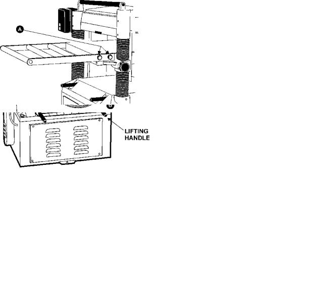
LIFTING HANDLES
There are four lifting handles, Figure 2, furnished with the machine. If any type of sling is used to lift the machine, be sure to attach to lifting handles only. Make sure machine is kept in level position while lifting. The lifting handles can be pushed back in when not in use.
STAND ASSEMBLY
For best planing performance, locate planer on solid, level foundation and anchor to the floor with good quality lag screws:
1.With machine in position, test table surface lengthwise and crosswise with machinist level. Place metal shims under low corners.
2.Check that all four corners are supported, then tighten lag screws.
3.Re-test level of table surface in both directions, and adjust if necessary.
TABLE EXTENSION ROLLERS
Mount the table extension rollers to the table using the provided hex hd. screws (A) and washers, Figure 3. The rollers should be adjusted before using the planer, see "Adjusting Table Extension Rollers" pg. 8.
FIGURE 3
MOTOR, MOTOR PULLEY & BELT
1. Assemble the motor pulley (A) to the motor shaft by aligning it with the key in the shaft, and tighten the screw (B) in the motor shaft, as shown in Figure 4.
FIGURE 2
FIGURE 4
6
2. Assemble the motor to the motor mounting plate (B), using the provided hardware (A), Figure 5.
FIGURE 5
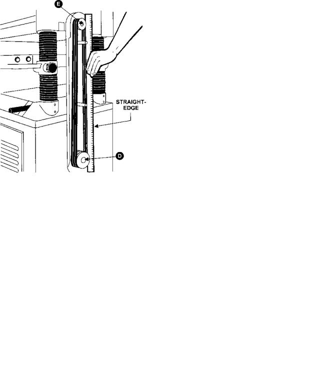
3. Using a straight edge, align the motor pulley (D) and cutterhead pulley (E) as shown Figure 6. The motor plate can be moved for alignment by loosening the set screws (C) in the motor plate
(B) as shown in Figure 5.
FIGURE 6
4. Assemble the belts to the two pulleys, Figure 6. Adjust for the proper belt tension by raising or lowering the motor plate (F), Figure 7, then tighten the nuts (G). Proper tension is obtained when there is approximately 1/4" deflection of the center span of the pulleys by using light finger pressure, Figure 8.
FIGURE 7
FIGURE 8
ADJUSTMENTS
TABLE ROLLER ADJUSTMENT
Your planer is supplied with two table rollers (A), Figure 9, which turn as the stock is fed into the planer, thus reducing friction. It is not possible to give exact dimensions on the proper height setting of the table rollers because each type of wood behaves differently.
As a general rule, however, when planing rough stock, the table rollers should be set at high position. When planing smooth stock the rollers should be set at low position.
NOTE: When raising the roller higher above the table, the range is from .003" to .006", see Figure 10.
7
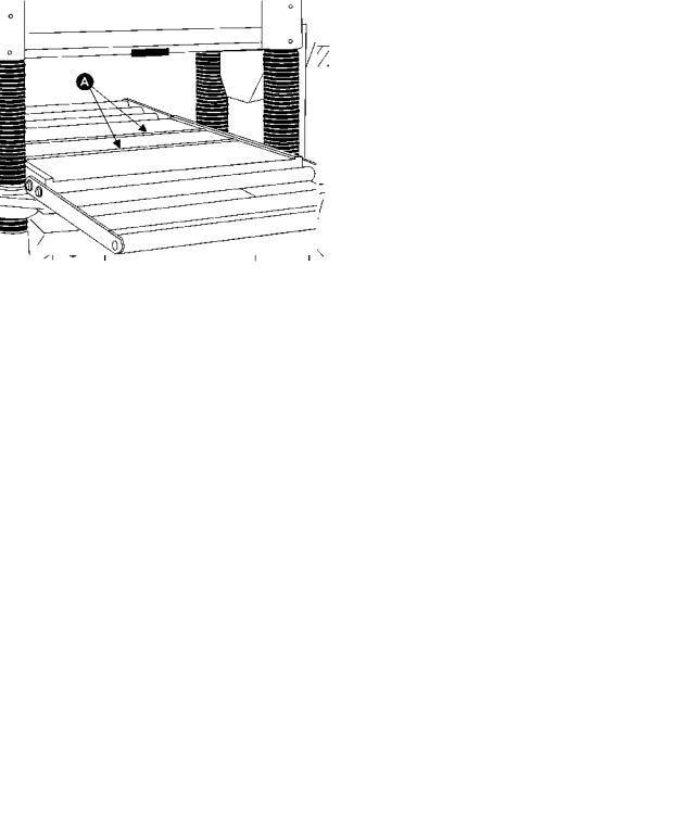
FIGURE 9 |
FIGURE 11 |
ADJUSTING TABLE EXTENSION
ROLLERS
FIGURE 10
The table rollers are factory set for average planing and are parallel to the table surface. If you desire to adjust the table rollers higher or lower, proceed as follows:
1.Disconnect machine from power source.
2.Lay a straight edge (B), Figure 11, across both rollers.
3.On one side of the table, loosen the screws
(C) with an Allen wrench, and turn the eccentric shafts (D) to raise or lower the rollers.
4.When the proper height is achieved, tighten screws (C).
5.Adjust the rollers from the opposite side of the table in the same manner.
IMPORTANT: Be sure that the height of front and rear rollers are the same. The table rollers must always be set parallel to the table.
Place a straight edge over the extension rollers and the table, as shown in Figure 12, to make sure the extension rollers and the table are at the same height.
If necessary, adjust the table extension rollers as follows:
1.Loosen the screws and washers (A) to move the table extension roller to the proper position, then retighten the screws.
2.Adjust both front and rear extension rollers in the same manner.
FIGURE 12
ADJUSTING DEPTH OF CUT
The cutting depth scale is a combination inch/metric scale (A), Figure 13, with a cutting range from 0 to 8" (204mm). The distance of upward or downward movement is controlled by the handwheel
(B). One revolution is .059" (1.5mm). Before
8
moving the table up or down, loosen the lock nuts
(C). After obtaining the proper table position, tighten the lock nuts (C).
FIGURE 13
CUTTERHEAD ADJUSTMENT
Although your planer was carefully adjusted at the factory, it should be checked before being put into operation. Any inaccuracies due to rough handling in transit can easily be corrected by following these directions.
To check the adjustments you will need a straight edge, feeler gauge, and a home-made gauge block made of hardwood. This gauge block can be made by following the dimensions shown in Figure 14.
FIGURE 14
KNIFE ADJUSTMENT
When checking or adjusting the cutterhead knives, proceed as follows:
1.Disconnect machine from power source.
2.Remove the six screws (A) and remove upper cover (B), Figure 15.
FIGURE 15
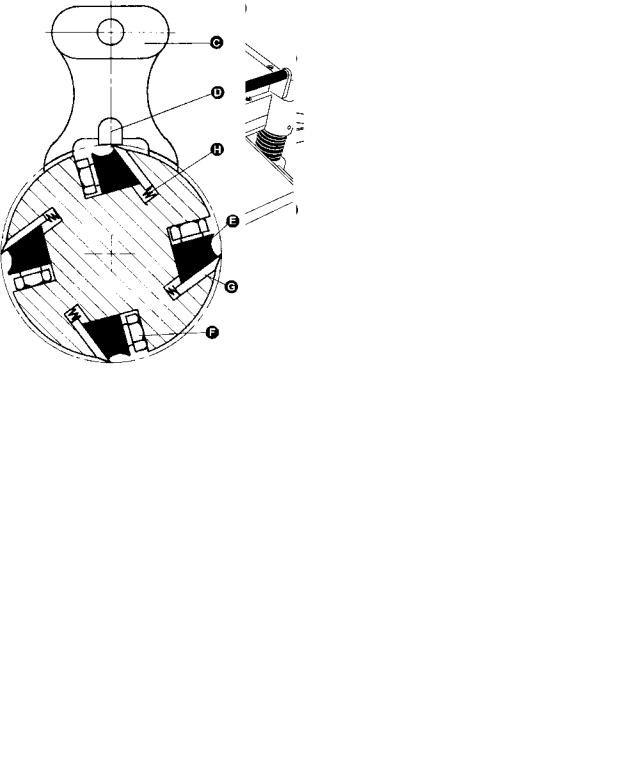
3. To check and adjust knives, use the provided knife gauge (C) and check all four knives, Figure 16. Knives should just contact the bottom of the center protrusion (D) of the knife gauge.
FIGURE 16
4. If an adjustment to one or more of the knives is necessary, slightly loosen the knife gib (E), Figure 16, by turning the six locking screws
9
 Loading...