


IMPORTANT MANUAL |
DO NOT THROW AWAY |
|||
|
|
|
|
|
|
|
|
|
|
|
|
|
|
|
|
|
|
|
|
REPAIR PARTS MANUAL
MODEL:
PP19A42
LAWN TRACTOR
WARNING:
Read this Manual and follow all Warnings and Safety Instructions. Failure to do so can result in serious injury.
ALWAYS WEAR EYE PROTECTION DURING OPERATION Visit our website: www.poulanpro.com
115 78 31-49 |
08.27.15 BD |
Printed in the U.S.A. |
HOW TO USE THIS MANUAL
This manual is designed to provide the customer with a means to identify the parts on his/her tractor when ordering repair parts. The illustrations may or may not represent the actual assemblies; therefore, it is not recommended to use this manual as a guide to assemble or disassemble the tractor. Some hardware and parts are drawn larger in order to more readily identify them.
Each tractor has its own model number.
The model number for your tractor can be found on the fender under the seat.
When ordering parts, always give the following information:
•Product - “TRACTOR”
•MODEL NUMBER - “PP19A42 (96046007700)”
•Part Number
•Part Description
TABLE OF CONTENTS |
|
SCHEMATIC ................................................................................................................ |
3 |
ELECTRICAL............................................................................................................ |
4-5 |
CHASSIS .................................................................................................................. |
6-7 |
DRIVE........................................................................................................................ |
8-9 |
ENGINE................................................................................................................. |
10-11 |
STEERING ............................................................................................................ |
12-13 |
MOWER DECK ..................................................................................................... |
14-15 |
MOWER LIFT............................................................................................................. |
16 |
SEAT .......................................................................................................................... |
17 |
DECALS..................................................................................................................... |
18 |
PARTS AND SERVICE.............................................................................................. |
20 |
2
TRACTOR - MODEL NUMBER PP19A42 (96046007700), PRODUCT NO. 960 46 00-77
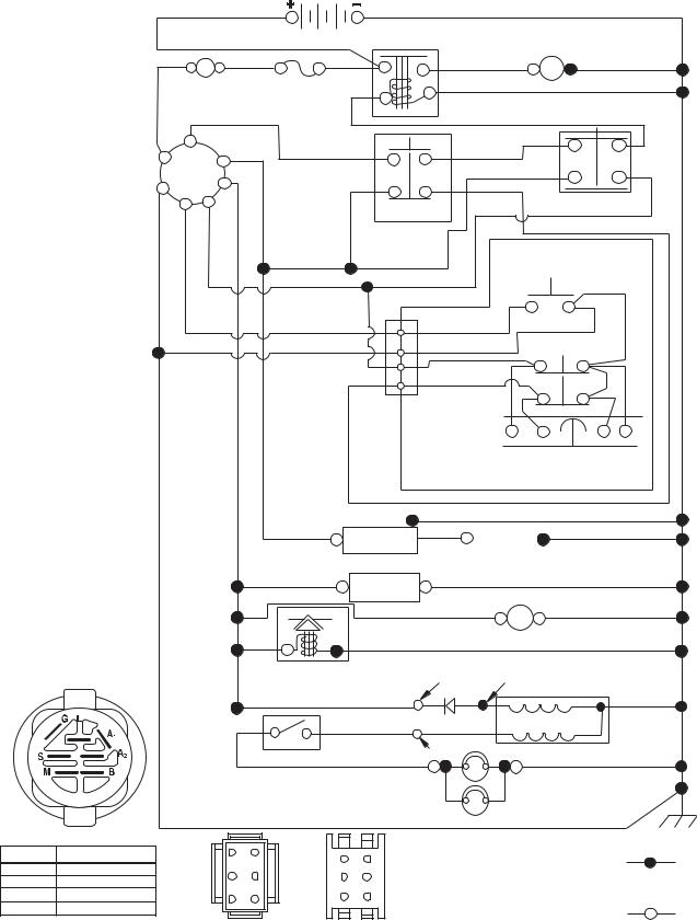
SCHEMATIC
SCH11
|
|
BATTERY |
SOLENOID |
|
|
|
|
STARTER |
|
|
|
|
|
|
RED |
A |
RED |
|
M |
|
AMMETER |
FUSE |
|
BLACK |
|
(OPTIONAL) |
|
|
|
|
|
|
|
|
|
WHITE |
|
|
WHITE |
NOTE
YOUR TRACTOR IS EQUIPPED WITH A SPECIAL ALTERNATOR SYSTEM. THE LIGHTS ARE NOT CONNECTED TO THE BATTERY, BUT HAVE THEIR OWN ELECTRICAL SOURCE.
BECAUSE OF THIS, THE BRIGHTNESS OF THE LIGHTS WILL CHANGE WITH ENGINE SPEED. AT IDLE THE LIGHTS WILL DIM. AS THE ENGINE IS SPEEDED UP, THE LIGHTS WILL BECOME THEIR
BRIGHTEST.
S |
M |
|
|
|
|
B |
|
|
|
|
|
G |
A1 |
|
|
|
|
A2 |
|
|
|
|
|
L |
|
|
|
ATTACHMENT CLUTCH |
|
|
|
|
|
|
(CLUTCH OFF) |
|
|
|
|
|
BLACK |
|
|
CLUTCH/BRAKE |
|
|
GRAY |
|
|
(PEDAL UP) |
|
|
|
|
BLACK |
|
|
|
REVERSE SWITCH |
|
|
|
|
(NOT IN REVERSE) |
|
|
|
|
|
|
|
|
|
|
|
BLACK |
|
|
BLACK |
|
|
|
|
|
|
2 |
|
BLACK |
|
|
BLACK |
3 |
|
|
SEAT SWITCH |
|
|
|
BLACK |
(NOT OCCUPIED) |
|
|
BLACK |
1 |
|
BLACK |
|
|
|
|
|
|
|
|
|
6 |
|
GRAY |
|
|
|
JUNCTION |
|
||
|
|
CONNECTOR |
|
||
|
/WHITE |
|
|
|
SHORTING |
|
BLACK |
CHASSIS |
|
|
|
|
|
|
CONNECTOR |
||
|
|
|
|
|
|
|
|
HARNESS |
|
|
|
|
|
IGNITION |
|
|
SPARK |
|
|
UNIT |
|
|
PLUGS GAP |
|
|
|
|
(2 PLUGS ON |
|
|
|
(OPTIONAL) |
TWIN CYL. ENGINES) |
||
|
|
|
|
|
|
|
BLUE |
HOUR |
|
|
BLACK |
|
|
METER |
|
|
|
BLACK |
FUEL |
|
|
|
12V |
|
LINE |
|
|
|
|
|
|
|
|
|
POWER OUTLET |
|
BLUE |
|
|
|
(OPTIONAL) |
|
FUEL SHUT-OFF |
CHARGING SYSTEM OUTPUT |
28 VOLTS AC MIN. @ 3600 RPM |
||
|
SOLENOID |
||||
|
3 AMP DC @ 3600 RPM |
|
(CHARGING SYSTEM DISCONNECTED) |
||
|
(IF SO EQUIPPED) |
|
|
|
|
|
RED |
|
|
|
|
|
LIGHTING SYSTEM OUTPUT |
DIODE |
ALTERNATOR |
|
|
5 AMP AC @ 3600 RPM |
|
||
LIGHT SWITCH |
ORANGE |
14 VOLTS AC MIN. @ 3600 RPM (LIGHTS OFF) |
||
|
||||
|
|
|||
|
BROWN |
|
|
BLACK |
HEADLIGHTS
IGNITION SWITCH |
|
|
|
|
||
POSITION |
CIRCUIT |
“MAKE” |
3 |
6 |
6 |
3 |
OFF |
M+G+A1 |
|
|
|
||
|
|
|
5 |
2 |
||
RUN/OVERRIDE |
B+A1 |
|
2 |
5 |
||
RUN |
B+A1 |
L+A2 |
1 |
4 |
4 |
1 |
START |
B + S + A1 |
|
||||
|
|
|
||||
|
|
|
|
|
||
|
|
|
CHASSIS HARNESS |
DASH HARNESS |
||
|
|
|
CONNECTOR |
CONNECTOR |
||
|
|
|
(MATING SIDE) |
(MATING SIDE) |
||
WIRING INSULATED CLIPS
NOTE: IF WIRING INSULATED CLIPS WERE REMOVED FOR SERVICING OF UNIT, THEY SHOULD BE RE-INSTALLED TO PROPERLY SECURE YOUR WIRING.
NON-REMOVABLE CONNECTIONS
REMOVABLE CONNECTIONS
3

REPAIR PARTS
TRACTOR |
- MODEL NUMBER |
PP19A42 (96046007700), PRODUCT NO. 960 46 00-77 |
||
ELECTRICAL |
|
|
|
|
TR02K |
|
|
22 |
|
|
|
|
33 |
|
|
|
|
|
|
Service Minder (If Equipped) |
79 |
|
30 |
|
21 |
|
|||
|
|
|
|
|
|
34 |
|
|
|
46 |
|
|
|
|
|
|
|
|
87 |
|
26 |
|
|
|
|
|
40 |
|
|
|
16 |
71 |
|
|
|
|
|
|
|
|
90 |
|
|
|
|
|
|
|
102 |
2 |
|
|
|
105 |
|
|
29 |
|
27 |
|
|
|
|
|
|
|
|
99 |
43 |
28 |
55 |
|
106 |
|
|
25 |
|
||
|
|
|
|
|
|
|
4 |
|
|
REPAIR PARTS
TRACTOR - MODEL NUMBER PP19A42 (96046007700), PRODUCT NO. 960 46 00-77
ELECTRICAL
KEY PART
NO. NO. DESCRIPTION
1532 14 49-25 Battery
2874 76 04-12 Bolt Hex Hd 1/4-20 unc x 3/4
8532 19 32-28 Box Battery
16532 17 61-38 Switch Interlock
21532 40 02-52 Harness Asm Light w/4152j
22532 00 41-52 Bulb Light #1156
25581 49 80-01 Cable Starter
26532 17 51-58 Fuse 20 AMP
27873 51 04-00 Nut Keps Hex 1/4-20 unc
28532 42 16-86 Cable Ground 6 Ga. 12" Black
29532 19 27-49 Switch Seat
30532 19 33-50 Switch Ign
33532 41 19-33 Key/Chain
34532 11 07-12 Switch Light/Reset
40581 02 31-01 Harness Ign Dash
43532 19 25-07 Solenoid
55817 06 05-12 Screw 5/16-18 x 3/4
71581 02 30-01 Harness Chassis
79532 17 52-42 Socket Asm. Bulb Twistlock
87532 19 78-02 Switch Interlock
90532 43 53-95 Cover Terminal Battery
99817 67 04-12 Screw Hexwsh Thdrol 1/4-20 x 3/4
102581 02 34-01 Harness Pigtail
105532 40 75-68 Switch Reverse
106532 17 48-14 Palnut 1/4 Lugs
NOTE: All component dimensions given in U.S. inches 1 inch = 25.4 mm.
5

REPAIR PARTS
TRACTOR - MODEL NUMBER PP19A42 (96046007700), PRODUCT NO. 960 46 00-77
CHASSIS
204 |
225 |
14
203 


237
5
176 |
|
|
|
|
237 |
176 |
|
202 |
|
176 |
|
|
|
|
176 |
|
177 |
|
|
182 |
195 |
|
175 |
|
|
|
|
|
176 |
|
|
36 |
196 |
37 |
194 |
|
||
181 |
|
|
|
68 |
|
|
|
|
|
|
194 |
|
|
138 |
15
297
18


 25 191
130
130
151
130
150
130 |
|
|
235 |
|
213 |
236 |
68 |
34 |
|
||
|
|
|
|
|
218 |
|
|
235 |
|
|
68 |
|
|
68 |
|
|
183 |
236 |
68 |
|
|
68 |
|
|
|
|
|
|
|
|
|
|
183 |
|
287 |
181 |
228 |
|
|
|
|
|
||
162 |
|
|
|
|
|
|
|
194 |
217 |
|
159 |
|
|
|
58 |
|
|
189 |
|
|
|
|
||
|
|
|
|
|
|
|
|
|
52 |
189 |
|
|
228 |
|
189 |
|
|
180 |
|
|
|
152 |
189 |
|
|
|
|
||
|
|
|
159 |
|
chassis-tex_TEX GT PRED II_21 |
|
|
|
|
|
|
|
|
6
REPAIR PARTS
TRACTOR - MODEL NUMBER PP19A42 (96046007700), PRODUCT NO. 960 46 00-77
CHASSIS
KEY PART
NO. NO. DESCRIPTION
5 532 44 18-82 Dash
14501 12 85-01 Hood
15581 10 31-01 Lens LH
18581 10 29-02 Grille
25581 10 30-01 Lens RH
34580 91 08-01 Plate Engine
36817 06 05-12 Screw 5/16-18 x 3/4
37532 42 07-96 Fender
52873 68 05-00 Nut Lock 5/16-18
58532 41 22-80 Drawbar Upper
68817 49 05-08 Screw Thdrol 5/16-18 x 1/2
130532 41 63-58 Screw #10 x 0.750
138532 40 97-30 Cupholder
150584 86 29-03 Duct Heat Hood
151532 44 54-94 Bracket Pivot
152532 19 95-35 Shield Browning
159817 00 06-12 Screw Hexwsh Thdrol 3/8-16 x 3/4
162532 14 24-32 Screw Hex Wsh Hi-Lo 1/4 x 1/2
175532 19 63-04 Crossmember
176532 40 07-76 Screw 10-24 x 5/8 Wshd Qdrx
177532 19 52-28 Bushing Steering
180532 41 50-63 Chassis
181532 40 47-96 Bushing Mtg. Fender Crgo.
182586 73 86-02 Dash Lower
183874 52 05-20 Bolt 5/16-18 x 1-1/4
189817 00 05-12 Screw 5/16-18 x 3/4
191581 22 35-01 Insert Reflector RH
194873 90 05-00 Nut Lock Hex Flange 5/16-18
195532 40 41-37 Plug Hole Dash Lower
196532 41 45-81 Console Asm. Deck Lift
202501 51 01-01 Vent Side Hood RH
203501 51 01-02 Vent Side Hood LH
204587 96 32-01 Vent Asm. Top
213874 76 05-12 Bolt 5/16-18 x 3/4
217532 40 91-67 Rod Pivot Hood
218532 19 63-95 X-Piece Hood Step
225581 10 32-01 Trim Ring
228532 19 51-61 Stud Fastener
235532 40 61-29 Spacer Fender
236873 93 05-00 Nut Center Lock 5/16-18
237532 40 37-04 Plug Mount Cargo
287817 60 04-06 Screw 1/4-20 x 3/8
297581 22 36-01 Insert Reflector LH - - 532 44 11-26 Plug Dash Srvmndr
NOTE: All component dimensions given in U.S. inches 1 inch = 25.4 mm
7
REPAIR PARTS
TRACTOR - MODEL NUMBER PP19A42 (96046007700), PRODUCT NO. 960 46 00-77
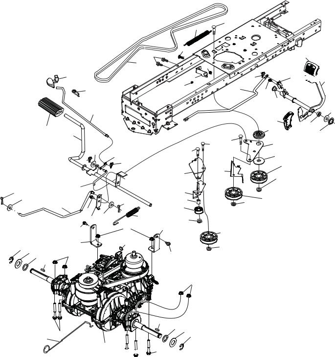
DRIVE
|
|
|
|
|
56 |
|
|
|
184 |
|
|
|
|
|
221 |
|
|
|
|
|
35 |
|
|
|
|
42 |
|
|
|
|
|
|
64 |
|
|
|
|
|
203 |
167 |
|
|
|
|
160 |
|
|
|
|
|
|
160 |
|
|
|
|
|
|
|
306 |
|
|
188 |
|
|
|
|
|
|
|
|
15 |
|
|
|
|
159 |
|
|
|
29 |
|
|
|
|
|
|
|
|
|
|
|
125 |
67 |
|
|
|
|
374 |
17 |
|
|
|
|
125 |
|
116 |
|
|
|
172 |
|
378 |
33 |
37 |
|
116 |
|
|
|
|
205 |
|
|
|
|
|
|
|
|
|
|
|
2 |
|
|
|
73
99
1
73

345
143 |
214 |
51
195 |
|
160 |
6 |
163 |
|
|
125 |
|
|
|
|
|
|
211 |
|
|
|
|
215 |
|
|
|
|
186 |
|
303 |
49 |
|
189 |
|
|
|
||
|
5 |
|
|
187 |
|
|
|
|
|
|
|
|
|
50 |
299 |
190 |
|
|
|
|
|
|
51 |
|
|
|
|
|
|
300 |
|
|
|
|
373 |
|
|
51 |
52 |
302 |
|
|
|
|
|
|
|
|
|
375 |
|
|
|
|
172 |
|
301 |
|
|
|
|
|
|
|
|
|
51 |
|
|
125 |
|
|
|
|
|
116 |
|
|
|
2
205 37
33
277 


 210
210
222
 211
211
166
282 |
drive-tex_VATR_PEDAL_33 |
8
REPAIR PARTS
TRACTOR - MODEL NUMBER PP19A42 (96046007700), PRODUCT NO. 960 46 00-77
DRIVE
KEY |
PART |
|
NO. |
NO. |
DESCRIPTION |
1 |
– – – – – – |
Transaxle, Variator SD Pedal |
|
|
(580486201) (Order parts from |
|
|
transaxle manufacturer.) |
2 |
532 12 35-83 |
Key Square |
5 |
874 76 06-36 |
Bolt Hex Hs 3/8-16 unc x 2-1/4 |
6 |
532 12 40-28 |
Bushing Snap |
15 |
819 13 13-16 |
Washer 13/32 x 13/16 x 16 Ga. |
17 |
584 95 40-01 |
Spring, Brake |
29 |
584 82 31-01 |
Rod, Brake |
33 |
812 00 00-01 |
Ring E |
35 |
583 86 45-01 |
Rod, Brake, Park |
37 |
532 18 89-67 |
Washer .793 x 1.637 x 060 |
42 |
532 12 48-72 |
Cover, Foot Pedal |
49 |
872 11 06-14 |
Bolt 3/8-16 unc |
50 |
532 19 43-27 |
Idler Flat |
51 |
873 90 06-00 |
Nut Lock 3/8-16 unc |
52 |
532 19 43-26 |
Idler V-Groove |
56 |
532 19 72-53 |
V-Belt, Drive |
64 |
532 44 83-53 |
Subasm. Shaft Pedal Brake |
67 |
819 13 13-12 |
Washer 13/32 x 13/16 x 12 Ga. |
73 |
874 49 05-44 |
Bolt Hex 5/16-18 x 3.75 |
99 |
532 43 59-35 |
Rod Bypass |
116 |
873 90 05-00 |
Nut Lock Hex Flange 5/16-18 |
125 |
817 00 05-12 |
Screw 5/16-18 x 3/4 |
143 |
817 49 05-08 |
Screw Thdrol 5/16-18 x 1/2 TYTT |
159 |
876 02 04-12 |
Pin Cotter 1/8 x 3/4 |
160 |
532 16 94-84 |
Retainer Clip |
161 |
532 10 57-09 |
Spring, Return, Clutch |
163 |
587 84 79-01 |
Rod Control |
166 |
532 42 91-64 |
Nut Push .625 |
167 |
532 40 52-57 |
Latch Brake Parking |
172 |
583 97 42-01 |
Strap Torque |
184587 65 37-01 Handle Park Brk.
185872 11 06-22 Bolt 3/8-16 unc x 2-3/4
KEY |
PART |
|
NO. |
NO. |
DESCRIPTION |
186532 19 43-21 Spacer Retainer
187819 13 32-10 Washer 13/32 x 2 x 10 ga
188532 19 43-23 Link Clutch Ground Drive
189532 19 43-17 Bellcrank Ground Drive
190532 19 43-18 Keeper. Bellcrank
195 |
581 50 46-01 |
Bracket Brake |
203 |
819 11 11-16 |
Washer 11/32 x 11/16 x 16 Ga. |
205 |
532 12 17-48 |
Washer 25/32 x 1-5/8 16 Ga. |
210 |
532 44 82-70 |
Rocker Asm. Pedal |
214 |
532 42 12-63 |
Pedal Forward |
215 |
532 44 82-54 |
Pad Pedal Reverse |
211 |
532 12 01-83 |
Bearing Nylon |
221 |
532 40 31-87 |
Retainer Spring |
222 |
879 21 20-10 |
Washer Flat |
277 |
532 44 85-00 |
Subasm. Link Rocker Pedal |
282 |
874 49 05-48 |
Screw Thdrol 5/16-18 x 3 |
299 |
532 41 56-83 |
Bracket Mount |
300 |
532 41 56-81 |
Keeper Idler |
301 |
532 41 56-80 |
Pulley Idler Groove |
302 |
581 42 05-01 |
Puller Idler Flat |
303 |
872 11 06-18 |
Bolt |
306 |
876 02 04-16 |
Pin Cotter 1/8 x 1 |
345 |
872 11 06-06 |
Bolt 3/8-16 unc |
373 |
581 46 18-01 |
Spacer Idler |
374581 47 52-01 Arm Control Brake
375873 68 06-00 Nut Crownlock 3/8-16 unc
378 584 28 77-01 Nut Push 8 mm
NOTE: All component dimensions given in U.S. inches 1 inch = 25.4 mm
9
REPAIR PARTS
TRACTOR - MODEL NUMBER PP19A42 (96046007700), PRODUCT NO. 960 46 00-77
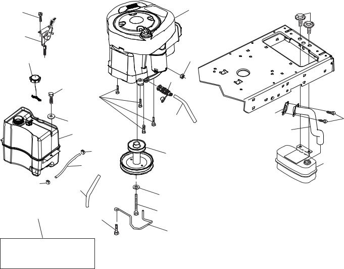
ENGINE
21 |
|
1 |
87 |
|
|
|
|
20 |
|
|
|
18 |
|
45 |
|
|
|
82 |
|
|
97 |
|
|
|
84 |
|
|
|
|
81 |
69 |
|
96 |
79 |
|
|
|
|
|
|
15 |
|
94 |
|
37 |
12 |
|
|
|
|
|
|
28 |
|
2 |
|
|
|
|
37 |
138 |
|
|
|
42 |
|
|
|
|
|
|
29 |
90 |
85 |
|
|
|
|
|
|
|
9 |
|
OPTIONAL EQUIPMENT
SPARK ARRESTER
engine-tex_BS_109
10
REPAIR PARTS
TRACTOR - MODEL NUMBER PP19A42 (96046007700), PRODUCT NO. 960 46 00-77
ENGINE
KEY PART
NO. NO. DESCRIPTION
1 – – – – – – Engine, B&S 33R877-0009-G1 (586070701) (Order parts from engine manufacturer.)
2 580 53 23-01 Muffler Exhaust B&S
9 584 91 16-01 Keeper Belt Engine
12 586 72 90-01 Pulley Engine
15 532 43 30-07 Tank Fuel Front
18 581 17 61-01 Cap Asm Fuel
20532 18 38-97 Control Th/Ch
21532 41 63-58 Screw #10 x 0.750
28532 40 11-37 Line Fuel
29532 13 71-80 Kit Spark Arrestor (Flat Scrn)
37532 12 34-87 Clamp Hose
42810 04 07-00 Washer Lock Hvy Hlcl Spr 7/16
45873 51 04-00 Nut Keps Hex 1/4-20 unc
69532 16 52-91 Gasket Eng 1 313 Id Tin Plated
79532 19 23-34 Screw Socket Head 5/16-18 x 3/4
81532 14 84-56 Tube Drain Oil Easy
82532 42 82-87 Valve Oil Drain
84817 06 06-20 Screw 3/8-16 x 1-1/4
85532 17 39-37 Bolt Hex 7/16-20 x 4 x Gr 5-1.5 Thr.
87532 17 18-77 Bolt 5/16-18 unc x 3/4 w/Sems
90817 00 06-16 Screw 3/8-16 x 1
94581 88 09-01 Exhaust Tube
96819 09 14-16 Washer 9/32 x 7/8 x 16 Ga.
97817 67 04-12 Screw Thdrol 1/4-20 x 3/4
138532 41 41-19 Purge Line
NOTE: All component dimensions given in U.S. inches 1 inch = 25.4 mm
For engine service and replacement parts, call the toll free number for your engine manufacturer listed below:
Briggs & Stratton |
1-800-233-3723 |
Engine Power Rating Information
The gross power rating for individual gas engine models is labeled in accordance with SAE (Society of Automotive Engineers) code J1940 (Small Engine Power & Torque Rating Procedure), and rating performance has been obtained and corrected in accordance with SAE J1995 (Revision 2002-05). Torque values are derived at 3060 RPM; horsepower values are derived at 3600 RPM. Actual gross engine power will be lower and is affected by, among other things, ambient operating conditions and engine-to-engine variability. Given both the wide array of products on which engines are placed and the variety of environmental issues applicable to operating the equipment, the gas engine will not develop the rated gross power when used in a given piece of power equipment (actual “on-site” or net power). This difference is due to a variety of factors including, but not limited to, accessories (air cleaner, exhaust, charging, cooling, carburetor, fuel pump, etc.), application limitations, ambient operating conditions (temperature, humidity, altitude), and engine-to- engine variability. Due to manufacturing and capacity limitations, Briggs & Stratton may substitute an engine of higher rated power for this Series engine.
11
REPAIR PARTS
TRACTOR - MODEL NUMBER PP19A42 (96046007700), PRODUCT NO. 960 46 00-77
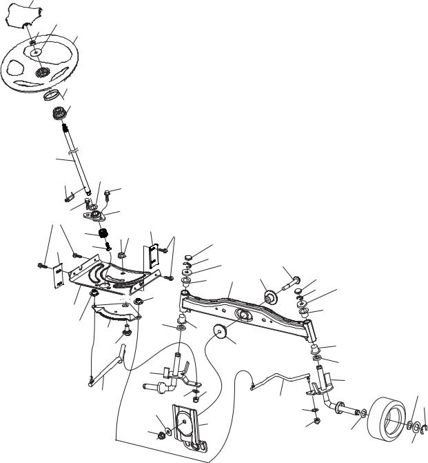
STEERING
26
45
50
1


 20
20

 21
21
16 |
|
|
64 |
|
27 |
|
28 |
|
|
|
|
28 |
|
22 |
63 |
|
|
|
75 |
60 |
|
|
|
57 |
76 |
|
|
|
59

19
122
35
58
61
57 |
63 |
|
|
|
|
|
|
|
|
|
|
|
9 |
|
|
|
|
|
8 |
7 |
|
66 |
|
|
|
|
|
||
|
74 |
2 |
67 |
9 |
|
122 |
|
|
|
8 |
7 |
|
|
|
|
|
|
|
|
|
|
|
74 |
6 |
74 |
|
|
|
|
|
|
|
|
|
|
|
|
|
67 |
|
74 |
|
|
|
|
|
6 |
4 |
|
|
|
|
5 |
|
|
|
|
|
|
|
15 |
|
|
|
|
|
14 |
|
|
62 |
|
|
|
|
|
|
|
69 |
|
|
|
14 |
|
|
|
|
|
|
|
68 |
70 |
|
|
15 |
13 |
|
|
|
13
8
53
steering-tex_STDSRR_47
12
 Loading...