

Page 1

PREV NEXT RETURN SELECT
XR-VS77
STEREO CD/VCD CASSETTE DECK RECEIVER
XR-VS77
XR-VS55
THIS MANUAL IS APPLICABLE TO THE FOLLOWING MODEL(S) AND TYPE(S).
Type
DBDXJ AC110-127V/220-230V/240V With the voltage selector
DLXJ/NC AC110-127V/220-230V/240V With the voltage selector
XR-VS77 XR-VS55 the following method.
Model
Power Requirement
The Voltage can be converted by
ORDER NO.
RRV2035
CONTENTS
1. SAFETY INFORMATION ...................................... 2
2. EXPLODED VIEWS AND PARTS LIST................ 3
3. SCHEMATIC DIAGRAM ..................................... 16
4. PCB CONNECTION DIAGRAM.......................... 34
5. PCB PARTS LIST ............................................... 46
6. ADJUSTMENT .................................................... 53
PIONEER ELECTRONIC CORPORATION 4-1, Meguro 1-Chome, Meguro-ku, Tokyo 153-8654, Japan
PIONEER ELECTRONICS SERVICE, INC. P.O. Box 1760, Long Beach, CA 90801-1760, U.S.A.
PIONEER ELECTRONIC (EUROPE) N.V. Haven 1087, Keetberglaan 1, 9120 Melsele, Belgium
PIONEER ELECTRONICS ASIACENTRE PTE. LTD. 501 Orchard Road, #10-00 Wheelock Place, Singapore 238880
PIONEER ELECTRONIC CORPORATION 1998
7. GENERAL INFORMATION ............................... 62
7.1 PARTS ......................................................... 62
7.1.1 IC ......................................................... 62
7.1.2 DISPLAY.............................................. 75
7.2 DISASSEMBLY ........................................... 79
7.3 BLOCK DIAGRAM....................................... 82
8. PANEL FACILITIES AND SPECIFICATIONS.... 84
T – ZZK OCT. 1998 Printed in Japan
Page 2
XR-VS77, XR-VS55
1. SAFETY INFORMATION
This service manual is intended for qualified service technicians ; it is not meant for the casual do-ityourselfer. Qualified technicians have the necessary test equipment and tools, and have been trained
to properly and safely repair complex products such as those covered by this manual.
Improperly performed repairs can adversely affect the safety and reliability of the product and may
void the warranty. If you are not qualified to perform the repair of this product properly and safely, you
should not risk trying to do so and refer the repair to a qualified service technician.
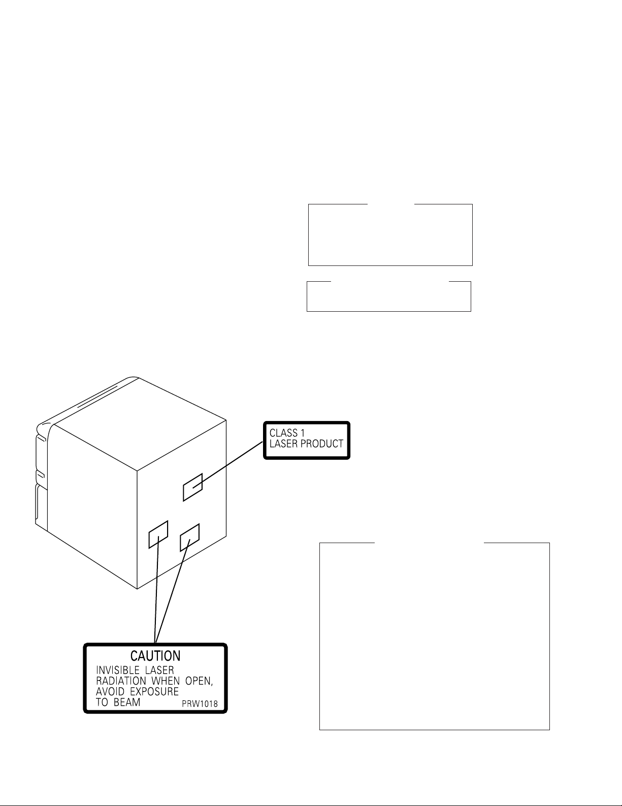
LABEL CHECK (For DLXJ/NC type)
THIS PIONEER APPARATUS CONTAINS
IMPORTANT
LASER OF CLASS 1.
SERVICING OPERATION OF THE APPARATUS
SHOULD BE DONE BY A SPECIALLY
INSTRUCTED PERSON.
LASER DIODE CHARACTERISTICS
MAXIMUM OUTPUT POWER: 1.3 mW
WAVELENGTH: 790 nm ± 25 nm
Printed on the Rear Panel
Additional Laser Caution
1.Laser Interlock Mechanism
The position of the switch (S8501) for detecting loading
state is detected by the system microprocessor, and
the design prevents laser diode oscillation when the
switch (S8501) is pressed physically.
Thus, the interlock will no longer function if the switch (S8501)
is released physically and deliberatery.
The interlock also does not function in the test mode ∗.
Laser diode oscillation will continue, if pin 62 of
LA9240ML (IC8101) on the CD ASSY mounted on the
$M Loading Mechanism assembly is connected to GND,
or else the terminals of Q8101 are shorted to each other
(fault condition).
2.When the cover is opened, close viewing of the objective
lens with the naked eye will cause exposure to a Class
1 laser beam.
∗
: Refer to page 61.
XR-VS55
/DLXJ/NC
XR-VS77
/DLXJ/NC
2
Page 3
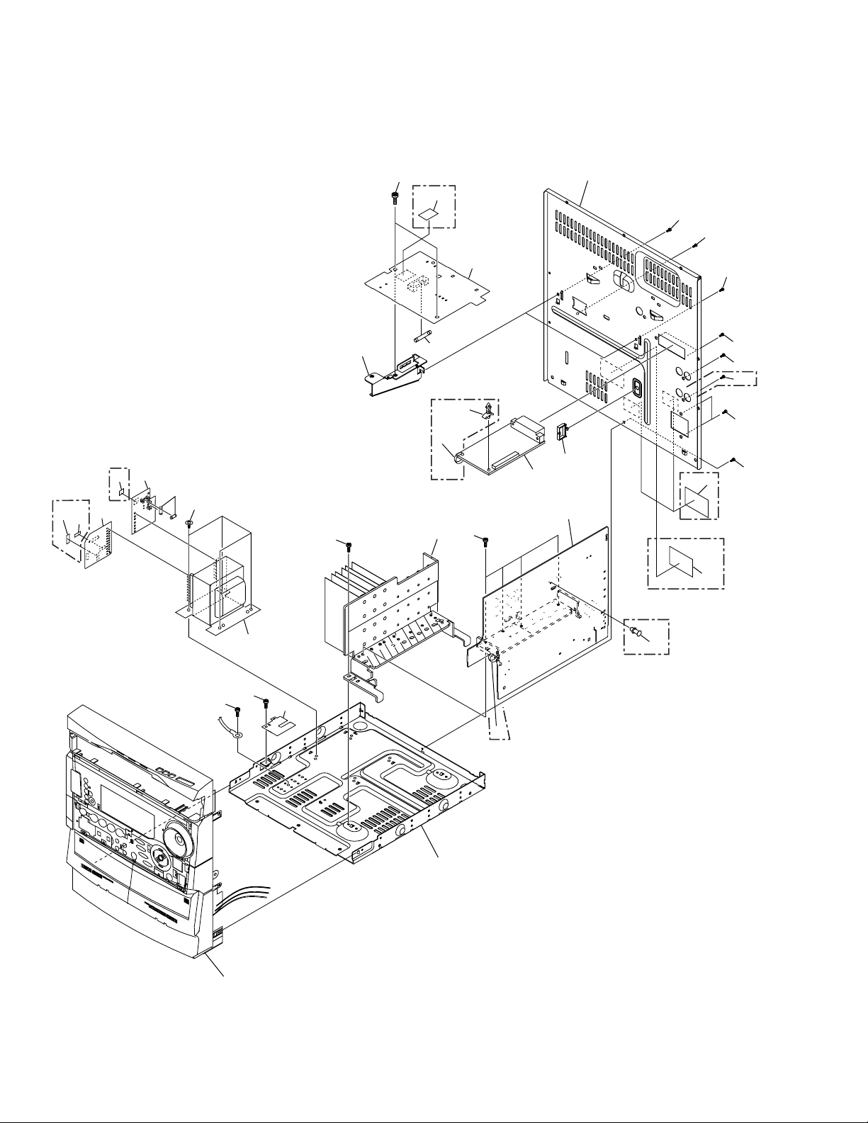
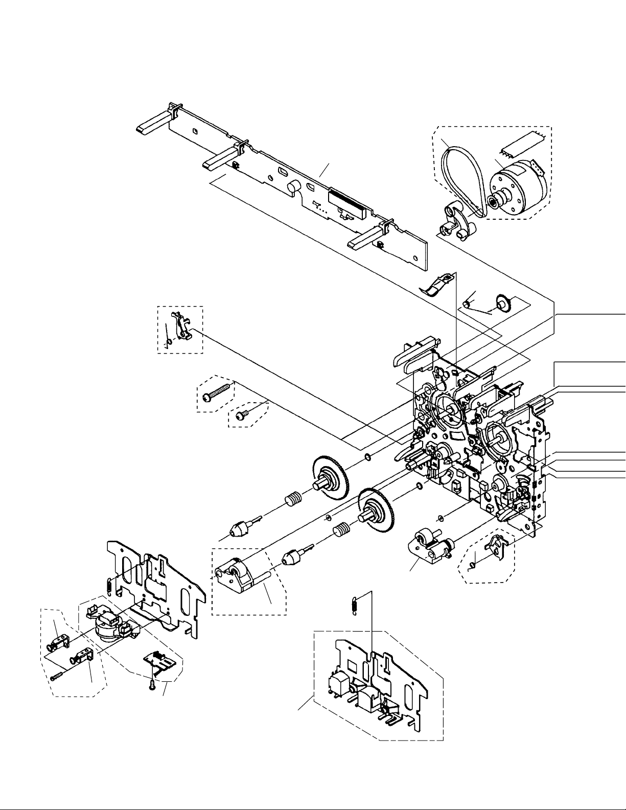
2. EXPLODED VIEWS AND PARTS LIST
XR-VS77, XR-VS55
NOTES:
Parts marked by "NSP" and can not be supplied.
•
The mark found on some component parts indicates the importance of the safety factor of the part.
•
Therefore, when replacing, be sure to use parts of identical designation.
Screws adjacent to mark on the product are used for disassembly.
•
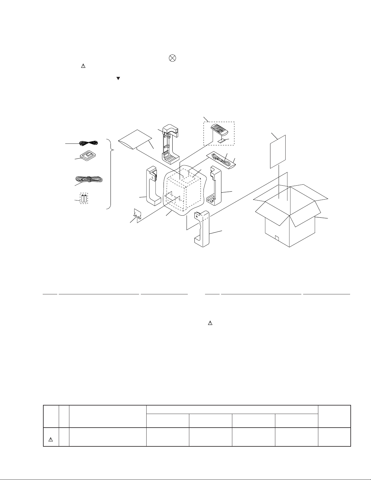
2.1 PACKING
1
3
17
6
8(1/2)
16
9(1/2)
4
VOL
K
A
R
A
O
K
E
S
DISC DISC DISC
F
S
C
L
E
E
P
P
.B
POWER
CLEAR
A
S
S
D
ISP
PGM
LA
Y
A
U
X
R
E
P
E
A
T
R
A
N
D
O
M
STATION
REMOTE CONTROL UNIT CU-XR025
MONOBAND
2
5
7
13
14
15
9(2/2)
11
10
8(2/2)
(1) PACKING PARTS LIST
Mark No. Description Part No.
1 FM Antenna ADH7004
2 Operating Instructions XRE3019
(English/Chinese/Chinese)
3 AM Loop Antenna XTB3001
4 Remote Control Unit XZN3009
(CU-XR051)
5 Battery Cover AZA7204
NSP 6 Dry Cell Battery (R6P, AA) VEM-013
7 Catalog Bag Z21-038
(0.03 × 230 × 340)
8 Front Pad XHA3003
Mark No. Description Part No.
9 Rear Pad XHA3004
10 Packing Case See Contrast table (2)
11 Packing Sheet AHG7049
12 • • • • •
13 Power Cord See Contrast table (2)
14 Polyethylene Bag AHG7033
NSP 15 Caution Card XAX3130
NSP 16 Door Spacer XHG3002
17 Video Cord VDE1034
(2) CONTRAST TABLE
XR-VS77/DBDXJ, DLXJ/NC, XR-VS55/DBDXJ and DLXJ/NC are constructed the same except for the following :
.oNtraP
kraM.oNnoitpircseDdnalobmyS
01esaCgnikcaP4503DHX7303DHX6503DHX9303DHX
31droCrewoP8511GDA4511GDA8511GDA4511GDA
77SV-RX
JXDBD/
77SV-RX
CN/JXLD/
55SV-RX
JXDBD/
55SV-RX
CN/JXLD/
skrameR
3
Page 4
XR-VS77, XR-VS55
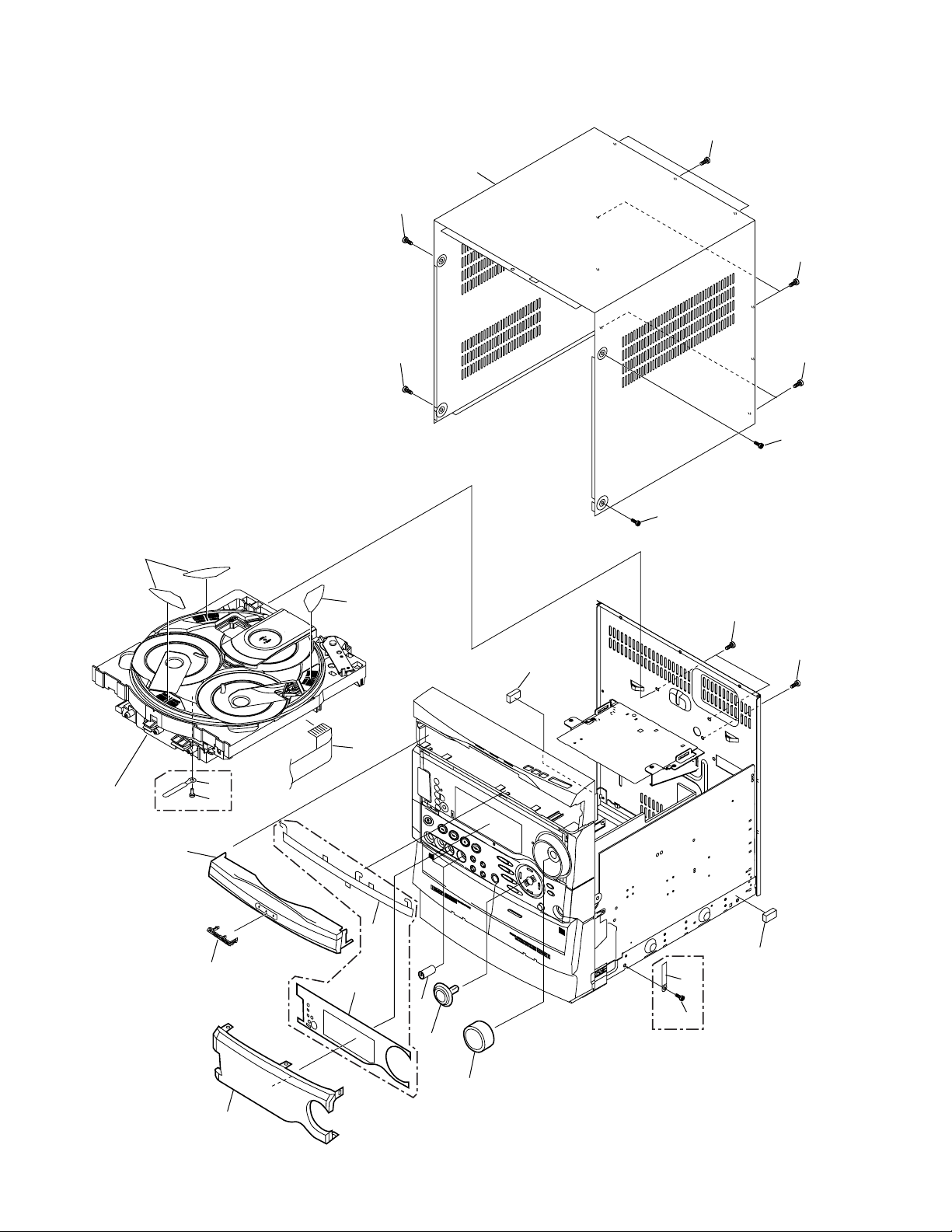
2.2 EXTERIOR (1/2)
Note :
Hook Tray cap on top of loading tray and then
insert the bottom three hooks.
Note :
Attatch on the same numbers × three.
12
21
15
8
9
15
21
9
21
2
Refer to
"2.5 $M MECHANISM VCD".
17
18
6
10
XR-VS55
only
12
9
19
1
4
5
20
13, 14
16
11
XR-VS77 only
9
19
3
7
XR-VS77 only
4
Page 5
(1) EXTERIOR (1/2) PARTS LIST
Mark No. Description Part No.
XR-VS77, XR-VS55
NSP 2 $M Mechanism VCD XXA3007
NSP 17 Cord Stopper See Contrast table (2)
1 16P F.F.C/30V XDD3006
3 Volume Knob See Contrast table (2)
4 FL Cover A See Contrast table (2)
5 FL Cover B See Contrast table (2)
6 Tray Cap See Contrast table (2)
7 Display Panel See Contrast table (2)
8 Bonnet Case See Contrast table (2)
9 Screw BPZ30P100FZK
10 Pioneer Badge AZN3049
11 Screw VBZ30P080FZK
12 Disc Label XAX3127
13 Jog Knob Assy See Contrast table (2)
14 Jog Knob See Contrast table (2)
15 Screw BCZ30P060FZK
16 Cord Clamper See Contrast table (2)
18 Push Rivet See Contrast table (2)
19 Cushion Rubber XEB3002
20 Mic Knob See Contrast table (2)
21 Screw VBT30P080FZK
(2) CONTRAST TABLE
XR-VS77/DBDXJ, DLXJ/NC, XR-VS55/DBDXJ and DLXJ/NC are constructed the same except for the following :
.oNtraP
kraM.oNnoitpircseDdnalobmyS
3bonKemuloV5003AAX5003AAX7003AAX7003AAX
4ArevoCLF6203KAX6203KAXdesutoNdesutoN
5BrevoCLF6303KAX6303KAXdesutoNdesutoN
6paCyarT7403NZX7403NZX8403NZX8403NZX
7lenaPyalpsiD5403KAX5403KAX2503KAX2503KAX
77SV-RX
JXDBD/
77SV-RX
CN/JXLD/
55SV-RX
JXDBD/
55SV-RX
CN/JXLD/
skrameR
8esaCtennoB9303NZX9303NZX5403NZX5403NZX
31yssAbonKgoJ4203GXX4203GXXdesutoNdesutoN
41bonKgoJdesutoNdesutoN9003AAX9003AAX
61repmalCdroC481-HNR481-HNRdesutoNdesutoN
PSN71reppotSdroCdesutoNdesutoN8211FND8211FND
81teviRhsuPdesutoNdesutoN8317CEA8317CEA
02bonKciM4003BAX4003BAX6003BAX6003BAX
5
Page 6
XR-VS77, XR-VS55
2.3 EXTERIOR (2/2)
XR-VS77
only
28
27
14
15
19
24
19
24
24
24
XR-VS77
only
24
19
XR-VS77
1
Except
DLXJ/NC Type
25
XR-VS55
DLXJ/NC Type only
26
19
XR-VS77
31
only
29
11
XR-VS55
only
3
30
2
6
21
19
7
13
32
22
4
19
5
19
19
Refer to
"2.4 FRONT PANEL SECTION".
17
33
XR-VS55
only
22
XR-VS77
only
8
6
Page 7
(1) EXTERIOR (2/2) PARTS LIST
XR-VS77, XR-VS55
Mark No. Description Part No.
1 AF Assy See Contrast table (2)
2 SECONDARY Assy See Contrast table (2)
3 PRIMARY Assy XWZ3048
4 FM/AM TUNER MODULE AXQ7065
5 T1 Power Transformer See Contrast table (2)
6 FU2, FU3 Fuse See Contrast table (2)
7 FU1 Fuse See Contrast table (2)
NSP 8 Chassis XNA3001
9 • • • • •
10 • • • • •
11 PCB Bracket XNG3006
12 • • • • •
13 Heat Sink See Contrast table (2)
14 Wire Clip XEC3002
15 Rear Panel See Contrast table (2)
Mark No. Description Part No.
16 • • • • •
NSP 17 SUPPORT Assy XNP3008
18 • • • • •
19 Screw VBZ30P080FZK
20 • • • • •
21 Screw ASZ40P060FMC
22 Binder ZCA-SKB90BK
23 • • • • •
24 Screw BPZ30P100FZK
25 Caution Label See Contrast table (2)
NSP 26 Name Label See Contrast table (2)
27 ICP Label See Contrast table (2)
28 ICP Label See Contrast table (2)
29 SUB TRANS Assy XWZ3049
NSP 30 Fuse Card See Contrast table (2)
NSP 31 Fuse Card See Contrast table (2)
32 Locking Spacer See Contrast table (2)
33 Card Spacer See Contrast table (2)
(2) CONTRAST TABLE
XR-VS77/DBDXJ, DLXJ/NC, XR-VS55/DBDXJ and DLXJ/NC are constructed the same except for the following :
.oNtraP
kraM.oNnoitpircseDdnalobmyS
1yssAFA2013ZWX2013ZWX8603ZWX8603ZWX
2yssAYRADNOCES3013ZWX3013ZWX9603ZWX9603ZWX
5remrofsnarTrewoP1T5103STX5103STX2103STX2103STX
6)A2T(esuF3UF,2UF7501KEA7501KEAdesutoNdesutoN
6)A6.1T(esuF3UF,2UFdesutoNdesutoN6501KEA6501KEA
77SV-RX
JXDBD/
77SV-RX
CN/JXLD/
55SV-RX
JXDBD/
55SV-RX
CN/JXLD/
skrameR
7)A4T(esuF1UF0601KEA0601KEAdesutoNdesutoN
7)A51.3T(esuF1UFdesutoNdesutoN9501KEA9501KEA
31kniStaeH2003HNX2003HNX3003HNX3003HNX
51lenaPraeR6003CNX6003CNX8003CNX8003CNX
52lebaLnoituaCdesutoN8101WRPdesutoN8101WRP
PSN62lebaLemaN8003LAXdesutoN3203LAXdesutoN
72lebaLPCI0213XAX0213XAXdesutoNdesutoN
82lebaLPCI1213XAX1213XAXdesutoNdesutoN
PSN03draCesuF7532XAA7532XAAdesutoNdesutoN
PSN13draCesuF9907XAA9907XAAdesutoNdesutoN
23recapSgnikcoLdesutoNdesutoN9003CEX9003CEX
33recapSdraCdesutoNdesutoN8003CEX8003CEX
7
Page 8
XR-VS77, XR-VS55
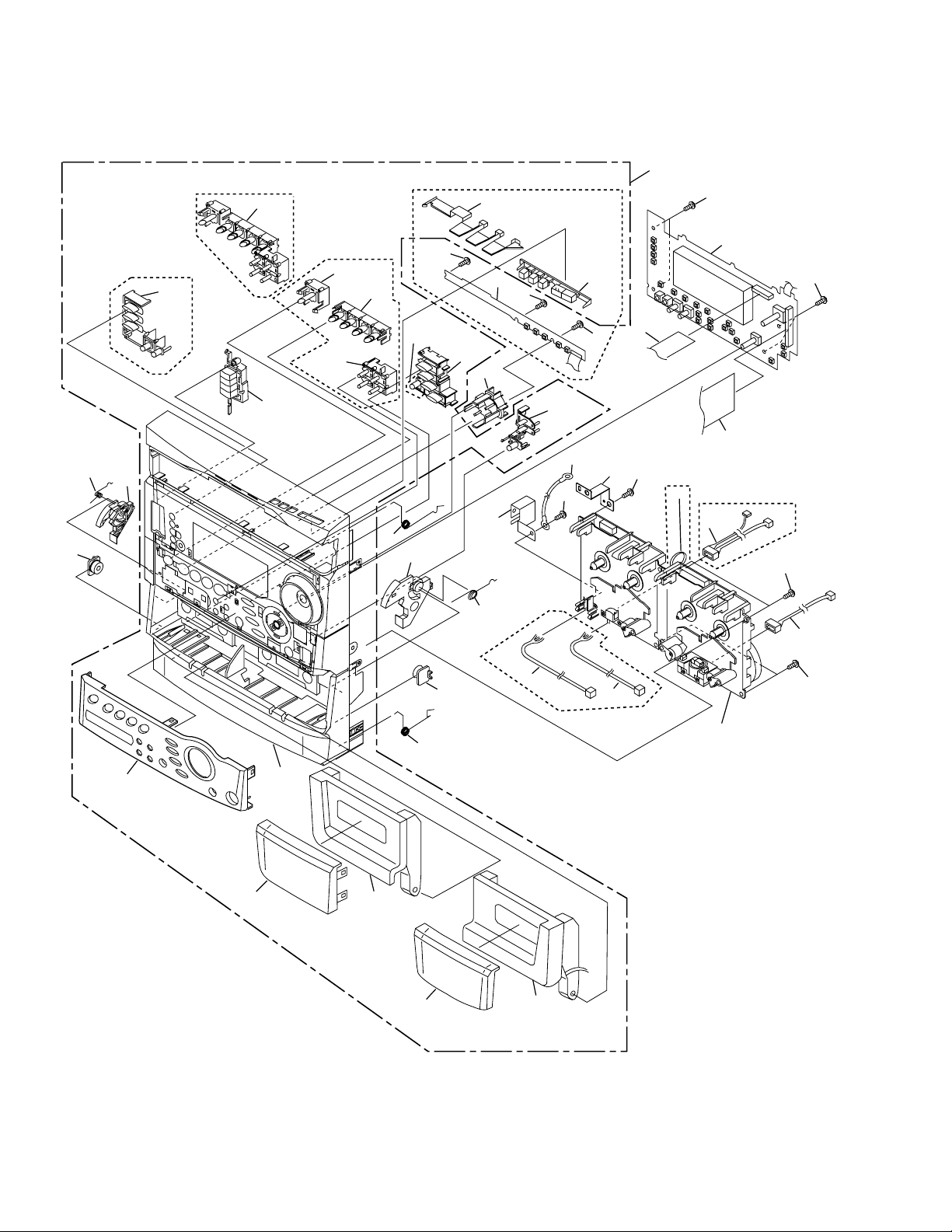
2.4 FRONT PANEL SECTION
XR-VS55 only
34
XR-VS77 only
26
23
17
21
15
XR-VS55 only
25
18
33
24
32
XR-VS77 only
34(1/2)
34(2/2)
35
13
XR-VS77
only
19
14
17
21
36
29
16
20
1
17
17
9
17
37
6
17
XR-VS55 only
25
17
11
5
7
17
XR-VS55 only
8
38
XR-VS77 only
10
12
Refer to "2.7 and 2.8
MECHANISM UNIT".
2
17
4
27
30
28
31
8
Page 9
(1) FRONT PANEL SECTION PARTS LIST
XR-VS77, XR-VS55
Mark No. Description Part No.
1 DISPLAY Assy See Contrast table (2)
2 CD SW LED Assy See Contrast table (2)
3 • • • • •
4 Connector Assy 2P See Contrast table (2)
5 Connector Assy 3P See Contrast table (2)
6 Cord With Plug DE007VE0
7 Flexible Cable See Contrast table (2)
8 Flexible Cable 40P XDD3005
9 Connector Assy 3P See Contrast table (2)
10 Connector Assy 5P See Contrast table (2)
11 GND Plate A XNG3004
12 Mechanism Unit See Contrast table (2)
13 Door Spring L XBH3001
14 Door Spring R XBH3002
15 Latch Spring L ABH7130
16 Latch Spring R ABH7131
17 Screw BPZ30P100FZK
18 Latch Mold L XMR3001
19 Latch Mold R XMR3002
20 GND Plate B XNG3005
Mark No. Description Part No.
21 Damper Assy AXA7052
22 • • • • •
NSP 23 Front Panel Assy See Contrast table (2)
24 Function Button See Contrast table (2)
25 CD Button See Contrast table (2)
26 CD Lens See Contrast table (2)
27 Deck Lens L XZN3035
28 Deck Lens R XZN3036
29 Jog Lens See Contrast table (2)
30 Door Pocket L See Contrast table (2)
31 Door Pocket R See Contrast table (2)
32 Front Panel See Contrast table (2)
33 Sub Panel A See Contrast table (2)
34 Power Button See Contrast table (2)
35 Play Button See Contrast table (2)
36 S.C. Button See Contrast table (2)
37 TIMER Button See Contrast table (2)
38 Binder See Contrast table (2)
(2) CONTRAST TABLE
XR-VS77/DBDXJ, DLXJ/NC, XR-VS55/DBDXJ and DLXJ/NC are constructed the same except for the following :
.oNtraP
kraM.oNnoitpircseDdnalobmyS
1yssAYALPSID4013ZWX4013ZWX0703ZWX0703ZWX
2yssADELWSDC6803ZWX6803ZWXdesutoNdesutoN
4P2yssArotcennoCdesutoNdesutoN2103EDX2103EDX
5P3yssArotcennoCdesutoNdesutoN1103EDX1103EDX
7P91elbaCelbixelF9003DDX9003DDXdesutoNdesutoN
7P71elbaCelbixelFdesutoNdesutoN0103DDX0103DDX
9P3yssArotcennoC1003EDX1003EDX9003EDX9003EDX
01P5yssArotcennoC2003EDX2003EDXdesutoNdesutoN
21tinUmsinahceM3003MYX3003MYX2003MYX2003MYX
PSN32yssAlenaPtnorF5103GXX5103GXX2103GXX2103GXX
42nottuBnoitcnuF0203NZX0203NZX1203NZX1203NZX
52nottuBDC8103NZX8103NZX9103NZX9103NZX
62sneLDC7303NZX7303NZXdesutoNdesutoN
92sneLgoJ5203KAX5203KAXdesutoNdesutoN
03LtekcoProoD3103NZX3103NZX4103NZX4103NZX
13RtekcoProoD5103NZX5103NZX6103NZX6103NZX
23lenaPtnorF1103NZX1103NZX2103NZX2103NZX
33lenaPbuS2303NZX2303NZX4303NZX4303NZX
43nottuBrewoP2203NZX2203NZX3203NZX3203NZX
53nottuByalP4203NZX4203NZXdesutoNdesutoN
63nottuB.C.S6203NZX6203NZX8203NZX8203NZX
73nottuBREMIT9203NZX9203NZX0303NZX0303NZX
83redniBdesutoNdesutoNKB09BKS-ACZKB09BKS-ACZ
77SV-RX
JXDBD/
77SV-RX
CN/JXLD/
55SV-RX
JXDBD/
55SV-RX
skrameR
CN/JXLD/
9
Page 10
XR-VS77, XR-VS55
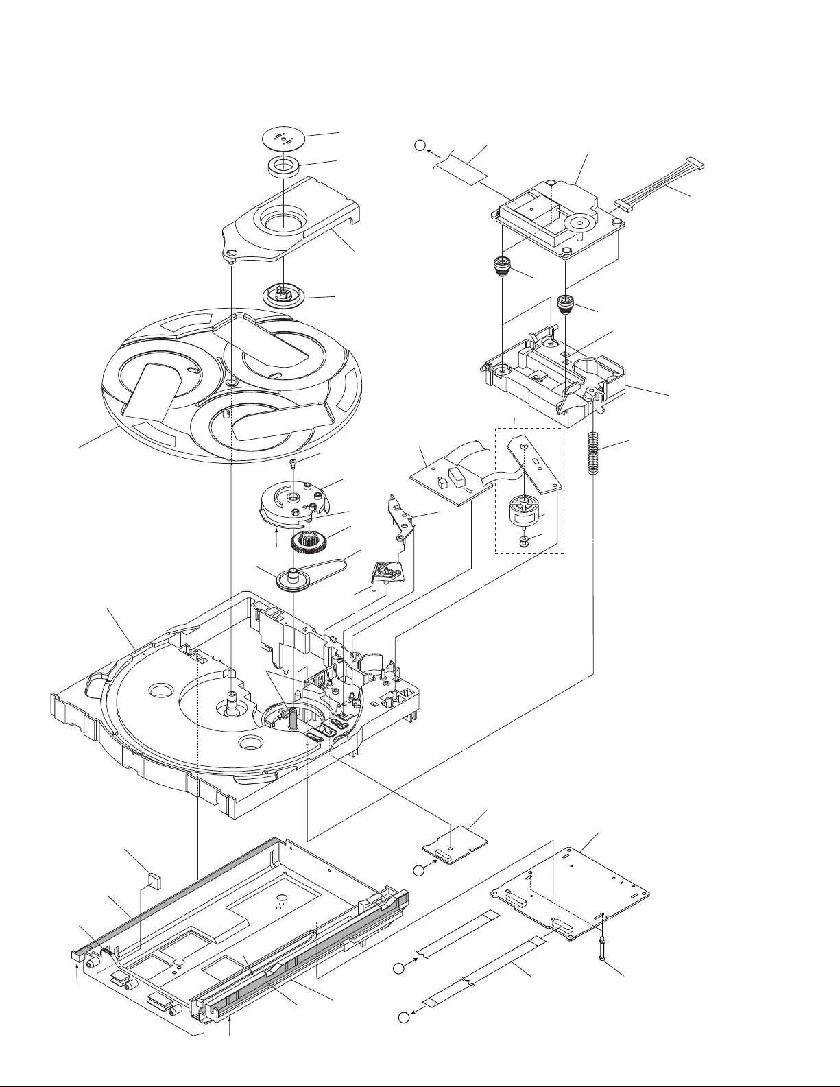
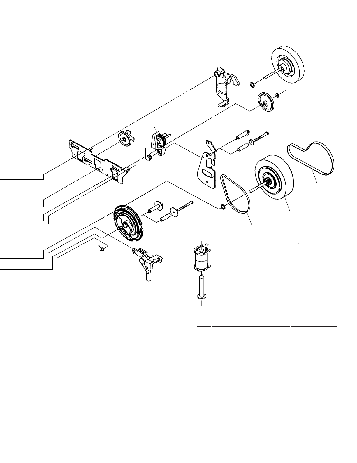
2.5 $M MECHANISM VCD
13
8
A
7
14
21
1
Refer to "2.6 SERVO MECHANISM ASSY".
25
22
24
23
11
12
10
31
16
29
29
26
17
15
29
18
2
19
6
4
27
28
5
3
10
29
29
29
29
29
29
B
A
9
B
3020
Page 11
$M MECHANISM VCD PARTS LIST
•
Mark No. Description Part No.
1 MOTOR Assy XWZ3080
NSP 2 SW Assy XWZ3081
3 VCD SURVO Assy XWX3003
4 TRADE Assy XWZ3082
5 Servo Spring ABH7126
6 Belt AEB7072
7 Clamp Magnet AMF7001
8 Yoke ANB7067
9 Mecha Base XNW3001
10 Loading Tray XNW3002
11 Servo Base XNW3003
12 Rotary Tray ANW7113
13 Clamper ANW7091
14 Clamper Holder XNW3004
15 Main Cam ANW7093
16 Gear Pully ANW7094
17 Lock Lever ANW7095
18 Planet Gear ANW7096
19 Actuater ANW7097
20 13P F.F.C/30V XDD3008
XR-VS77, XR-VS55
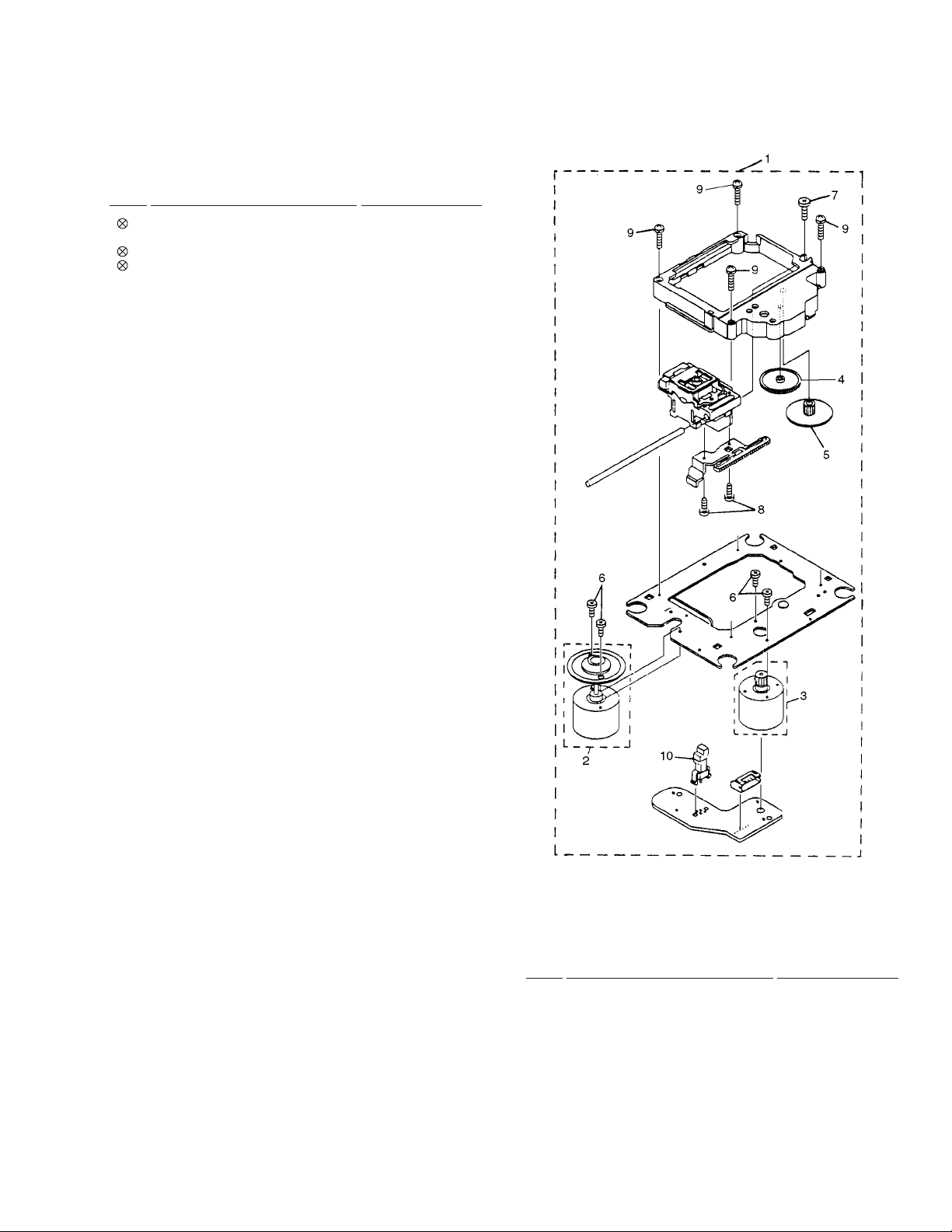
2.6 SERVO MECHANISM ASSY
21 15P F.F.C/30V XDD3007
22 Connector Assy (6P) ADE7010
23 Float Rubber A AEB7063
24 Float Rubber B AEB7066
25 Servo Mechanism Assy AXA7039
26 Screw IPZ30P080FMC
27 Carriage Motor VXM1033
28 Motor Pulley PNW1634
29 Ha Narl GEM1016
30 Card Spacer AEC7143
31 Cushion Rubber XEB3004
SERVO MECHANISM ASSY PARTS LIST
•
Mark No. Description Part No.
1 Servo Mechanism AXA7039
2 SPINDLE MOTOR Assy AEA7009
3 SLEAD MOTOR Assy AEA7010
4 Gear A AEA7013
5 Gear B AEA7014
6 Screw AEA7015
7 Screw AEA7016
8 Screw AEA7017
9 Screw AEA7018
10 Leaf Switch AEA7011
11
Page 12
XR-VS77, XR-VS55
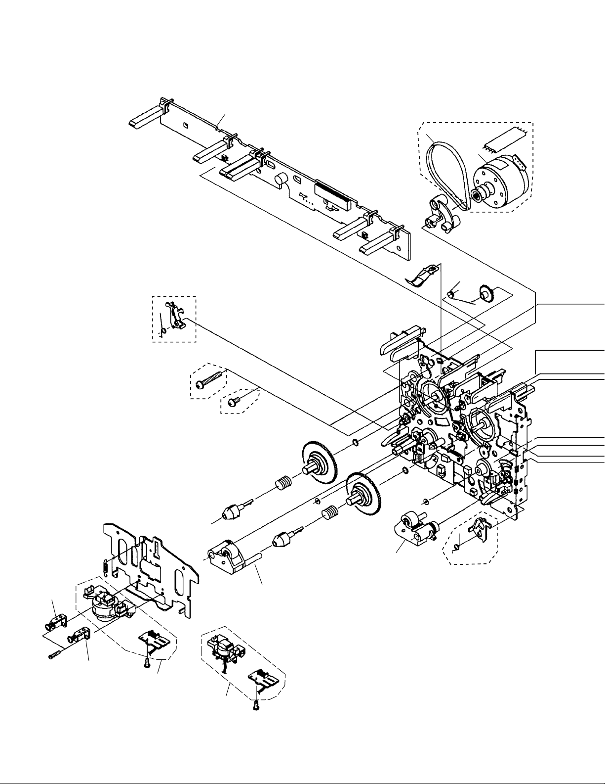
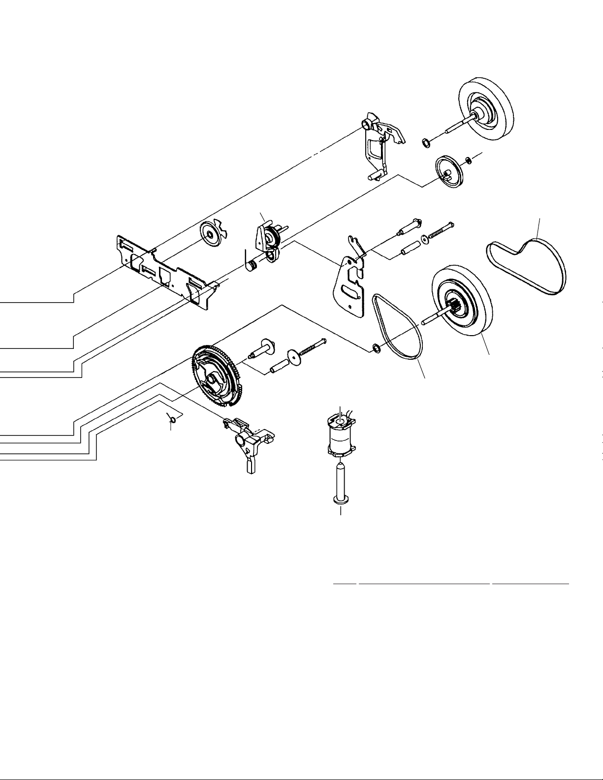
2.7 MECHANISM UNIT (XR-VS77)
Mech. Ι
Only
Mech. ΙΙ
4
Mech. ΙΙ
Only
7
2
12
Mech. Ι
13
Mech. Ι
9
Mech. ΙΙ
Only
10
1
1
Mech. ΙΙ
12
Page 13
XR-VS77, XR-VS55
5
8
11
6
MECHANISM UNIT PARTS LIST
•
Mark No. Description Part No.
1 Plate HD BLK (Mech. ΙΙ) F513-811
1 Plate HD BLK (Mech. Ι) F513-819
2 Motor Main BLK (Mech. ΙΙ only) F525-324
3 • • • • •
4 PCB Control BLK F567-621
5 Clutch Assy BLK F522-037
6 Main Belt FF17G-31
7 Joint Belt 113 (Mech. ΙΙ only) FF19D-21
8 Clutch Assy BLK F522-045
9 Roller Pinch BLK R F514-129
10 Roller Pinch BLK L F514-130
11 F/R Belt FF18W-12
12 Plate Base BLK F512-127
13 Plate Base BLK F512-128
13
Page 14
XR-VS77, XR-VS55
2.8 MECHANISM UNIT (XR-VS55)
Mech. ΙΙ
Only
6
Mech. Ι
Only
Mech. ΙΙ
Mech. Ι
4
2
12
Mech. ΙΙ Only
14
Mech. ΙΙ
9
Mech. ΙΙ
Only
10
Mech. ΙΙ
Only
13
1
1
Mech. Ι
Page 15
XR-VS77, XR-VS55
5
8
11
MECHANISM UNIT PARTS LIST
•
Mark No. Description Part No.
1 Plate HD BLK (Mech. ΙΙ) F513-811
1 Plate HD BLK (Mech. Ι) F513-825
2 Motor Main BLK (Mech. ΙΙ only) F525-324
3 • • • • •
4 PCB Control BLK F567-622
6
5 Clutch Assy BLK F522-037
6 Main Belt FF17G-31
7 • • • • •
8 Clutch Assy BLK (Mech. ΙΙ) F522-045
8 Clutch Assy BLK (Mech. Ι) F522-038
9 Roller Pinch BLK R (Mech. ΙΙ) F514-129
9 Roller Pinch BLK R (Mech. Ι) F514-131
10 Roller Pinch BLK L (Mech. ΙΙ only) F514-130
11 F/R Belt FF18W-12
12 Plate Base BLK (Mech. ΙΙ only) F512-127
13 Plate Base BLK (Mech. ΙΙ only) F512-128
15
Page 16
1
XR-VS77, XR-VS55
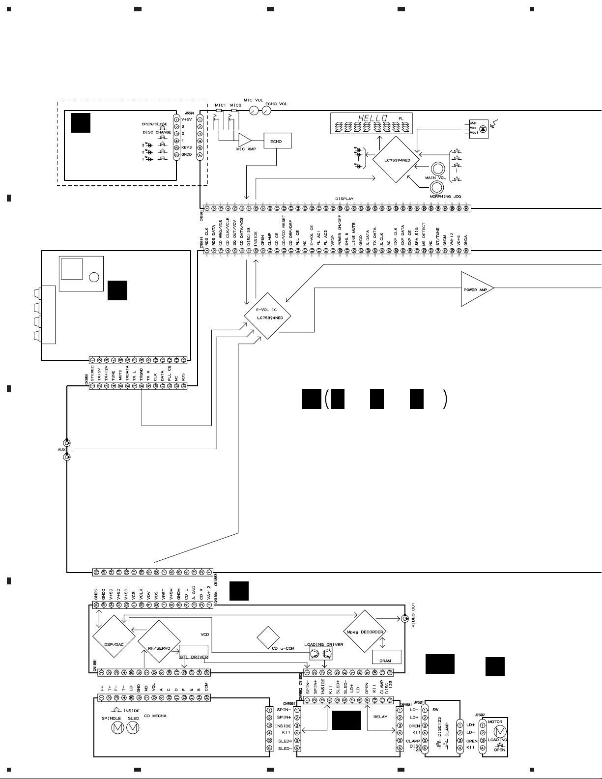
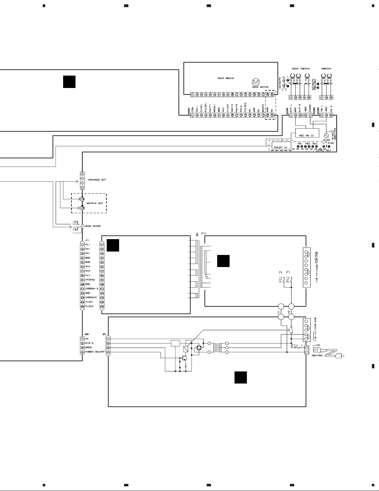
3. SCHEMATIC DIAGRAM
3.1 OVERALL WIRING DIAGRAM
A
J
CD SW LED
ASSY
(XWZ3086)
XR-VS77 ONLY
23
4
B
C
A
FM/AM TUNER
MODULE
(AXQ7065)
CN6201
E
E
AF ASSY
(XR-VS77 : XWZ3102)
(XR-VS55 : XWZ3068)
E E
1/3, 3/3
2/3,
B
VCD SURVO ASSY (XWX3003)
D
DA
SW ASSY
(XWZ3081)
C
MOTOR
ASSY
(XWZ3080)
DB
TRADE ASSY
(XWZ3082)
16
SERVO MECHANISM ASSY
(AXA7039)
1234
Page 17
5
678
XR-VS77, XR-VS55
Note : When ordering service parts, be sure to refer to "EXPLODED VIEWS and P AR TS LIST" or "PCB PARTS LIST".
I
DISPLAY ASSY
(XR-VS77 : XWZ3104)
(XR-VS55 : XWZ3070)
XR-VS77 ONLY
XR-VS77 ONLY
AEK7071
A
B
XR-VS77 ONLY
F
SECONDARY
ASSY
(XR-VS77 : XWZ3103)
(XR-VS55 : XWZ3069)
G
PRIMARY ASSY
(XWZ3048)
C
H
SUB TRANS ASSY
(XWZ3049)
D
17
5
6
7
8
Page 18
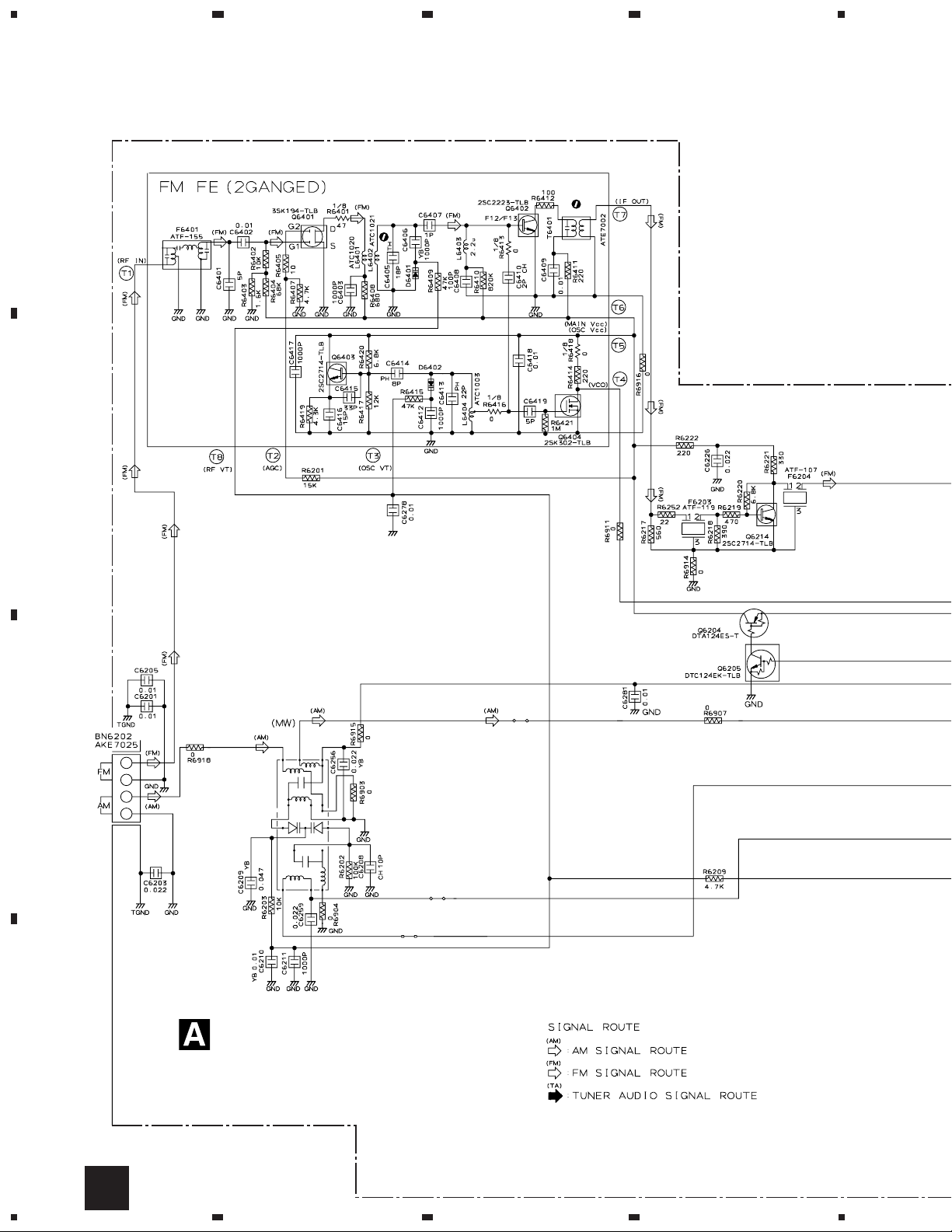
1
RF AMP
1T378A
1T378A
MIX AMP
BUFFER
IF AMP
FM +B SW
MW RF TUNING BLOCK
AKX7041
OSC
FM/AM TUNER MODULE
(AXQ7065)
XR-VS77, XR-VS55
3.2 FM/AM TUNER MODULE
A
23
4
B
C
D
18
A
1234
Page 19
5
678
XR-VS77, XR-VS55
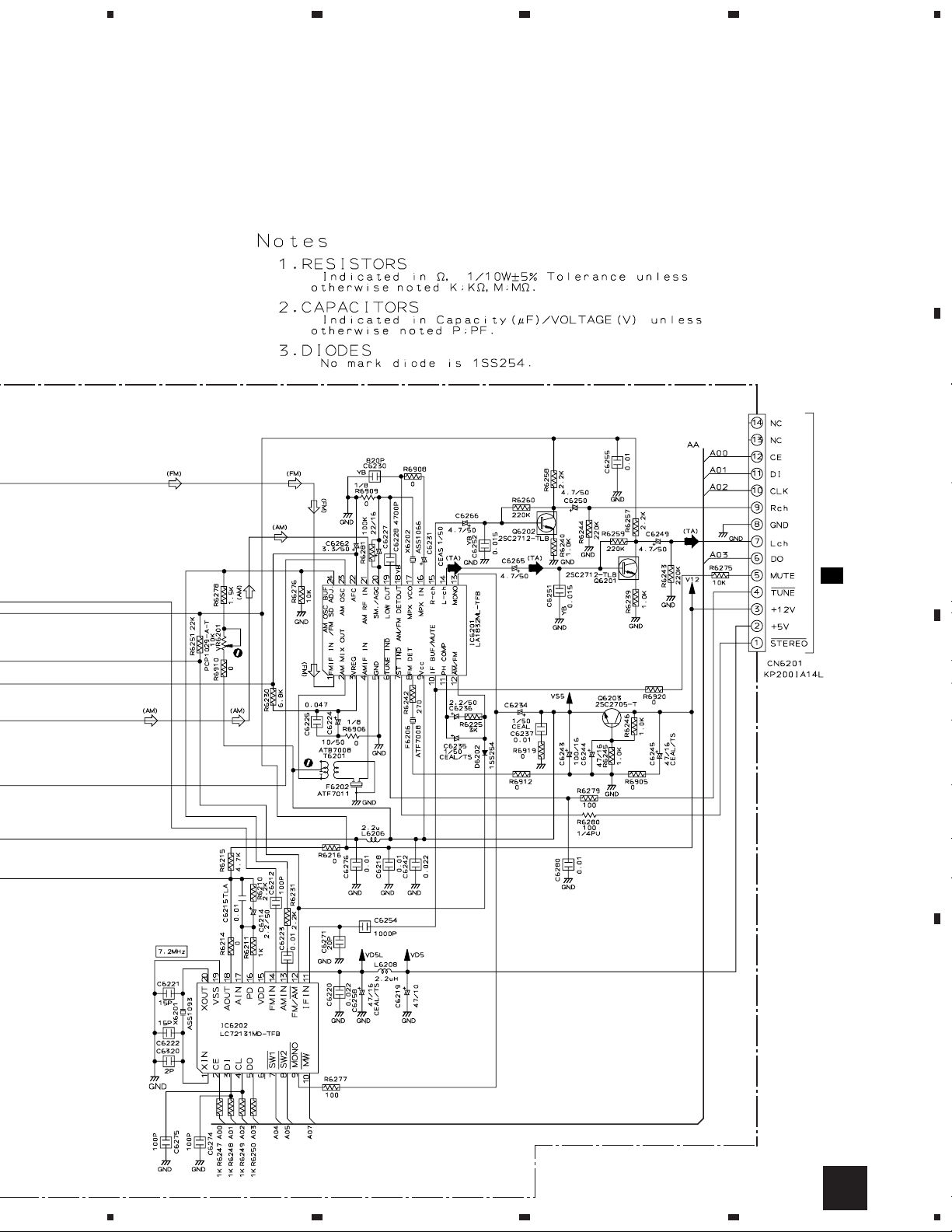
A
B
AF AMP
AF AMP
REGULATOR
CN3051
2/3E
C
PLL
D
A
5
6
7
8
19
Page 20
1
23
XR-VS77, XR-VS55
3.3 VCD SURVO, MOTOR, SW and TRADE ASSEMBLIES
4
2
A
B
1
C
TRADE ASSY
(XWZ3082)
DB
D
DA
20
SW ASSY (XWZ3081)
1/2B
1234
DA DB
Page 21
5
678
XR-VS77, XR-VS55
A
2/2
B
B
C
MOTOR ASSY
(XWZ3080)
5
Note: The encircled numbers
denote measuring point in the
schematic diagram.
CN1003- Pin 3 :
1
PLAY MODE (RF)
H : 500nsec/div
2.0Vp-p
VREF
6
2/2
B
B
1/2
CN1003- Pin 2 :
2
TEST MODE,
Tracking Open(TRER)
H : 5msec/div
1.0Vp-p
VREF:CN1003- Pin1
7
2/2
B
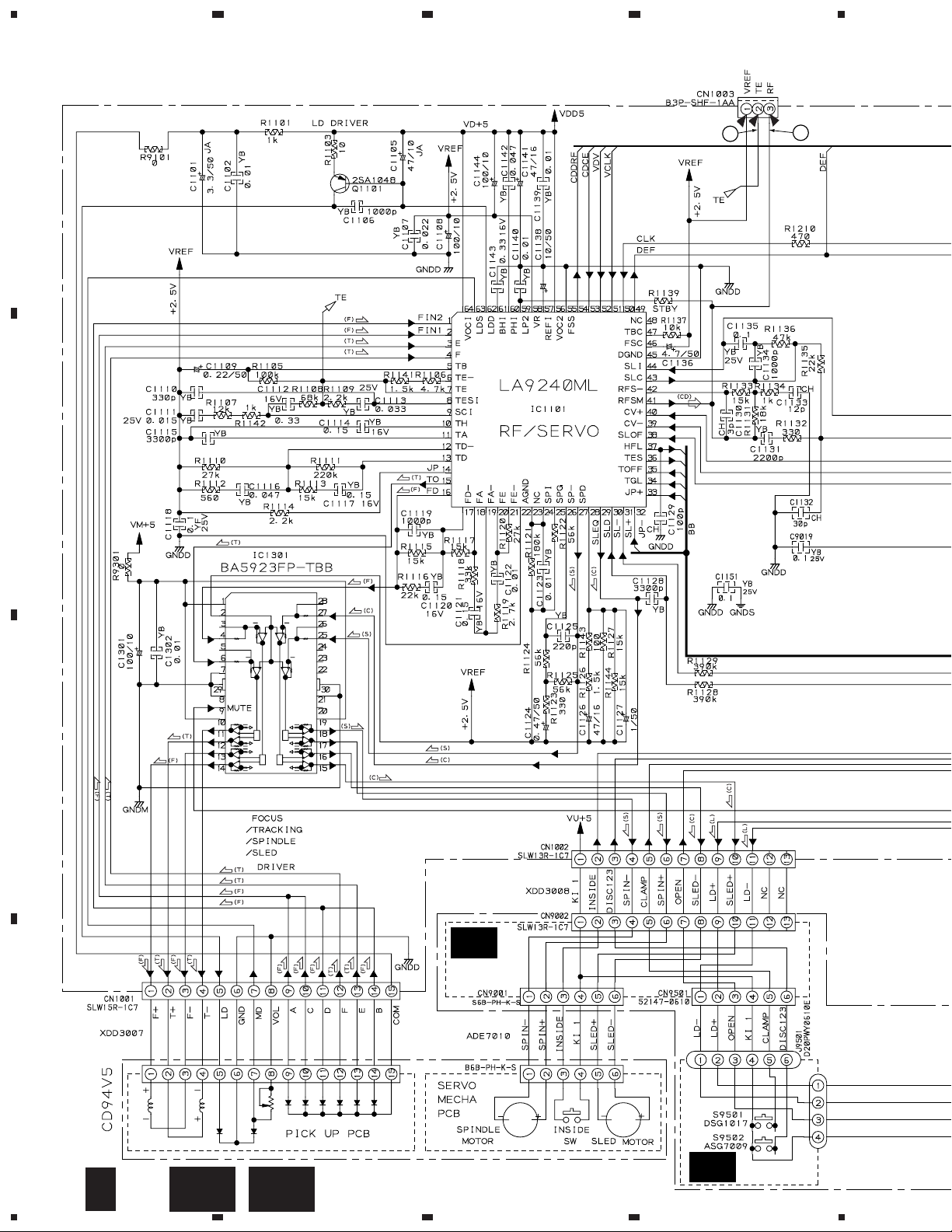
VCD SURVO ASSY (1/2)
(XWX3003)
SIGNAL ROUTE
(CD)
:CD AUDIO SIGNAL ROUTE
(FS)
: FOCUS SERVO LOOP LINE
(TS)
: TRACKING SERVO LOOP LINE
(SM)
: SPINDLE MOTOR ROUTE
(CM)
: CARRIAGE MOTOR ROUTE
(LM)
VREF
: LOADING MOTOR ROUTE
1/2B
C
8
C
D
21
Page 22
1
XR-VS77, XR-VS55
A
B
23
4
C
D
22
2/2B
1234
Page 23
5
678
XR-VS77, XR-VS55
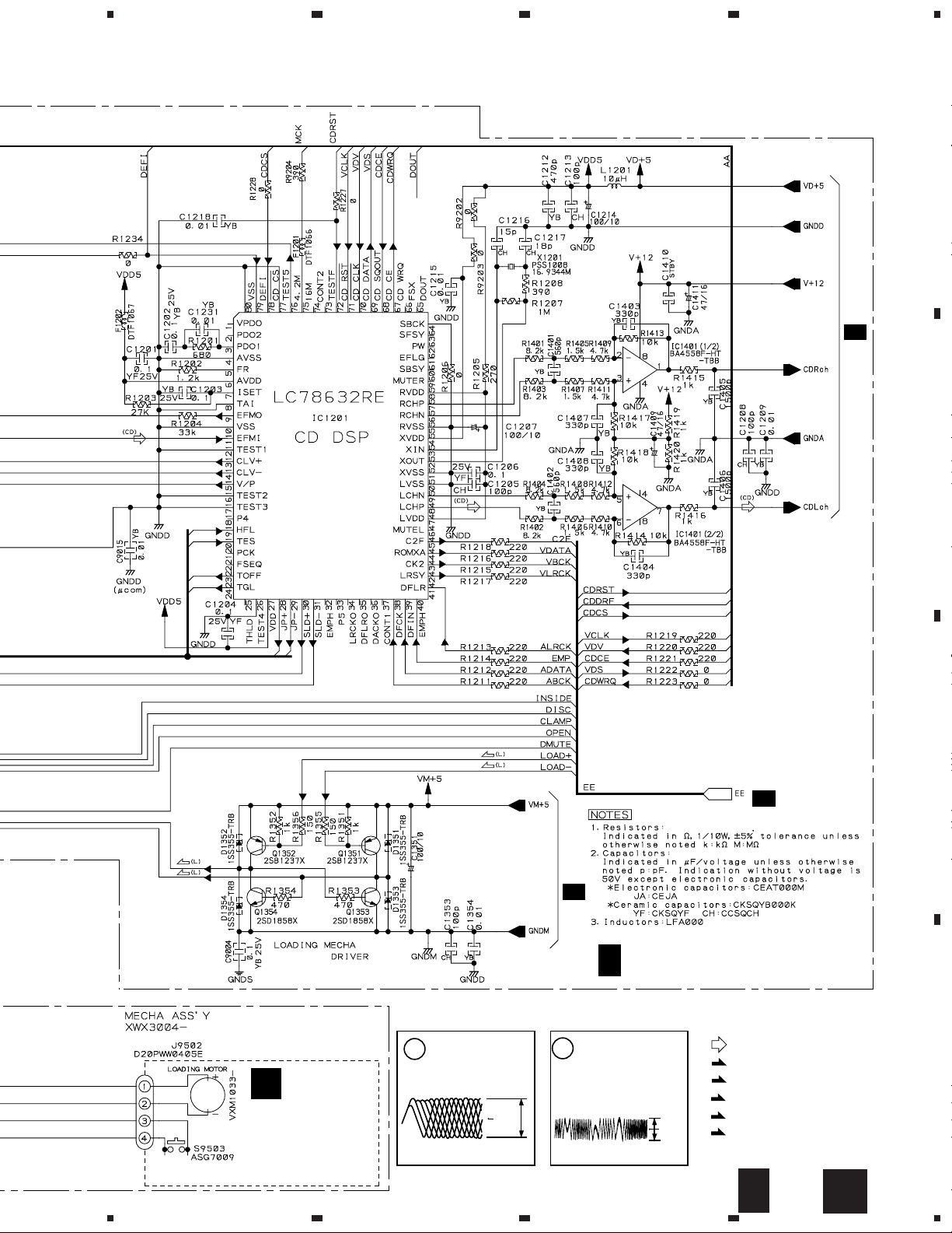
SIGNAL ROUTE
(CD)
:CD AUDIO SIGNAL ROUTE
A
1/2
B
B
B
(CD)
VCD SURVO ASSY (2/2)
2/2
(XWX3003)
CN1053
2/3
E
C
(CD)
1/2
B
D
5
6
7
8
2/2B
23
Page 24
1
XR-VS77, XR-VS55
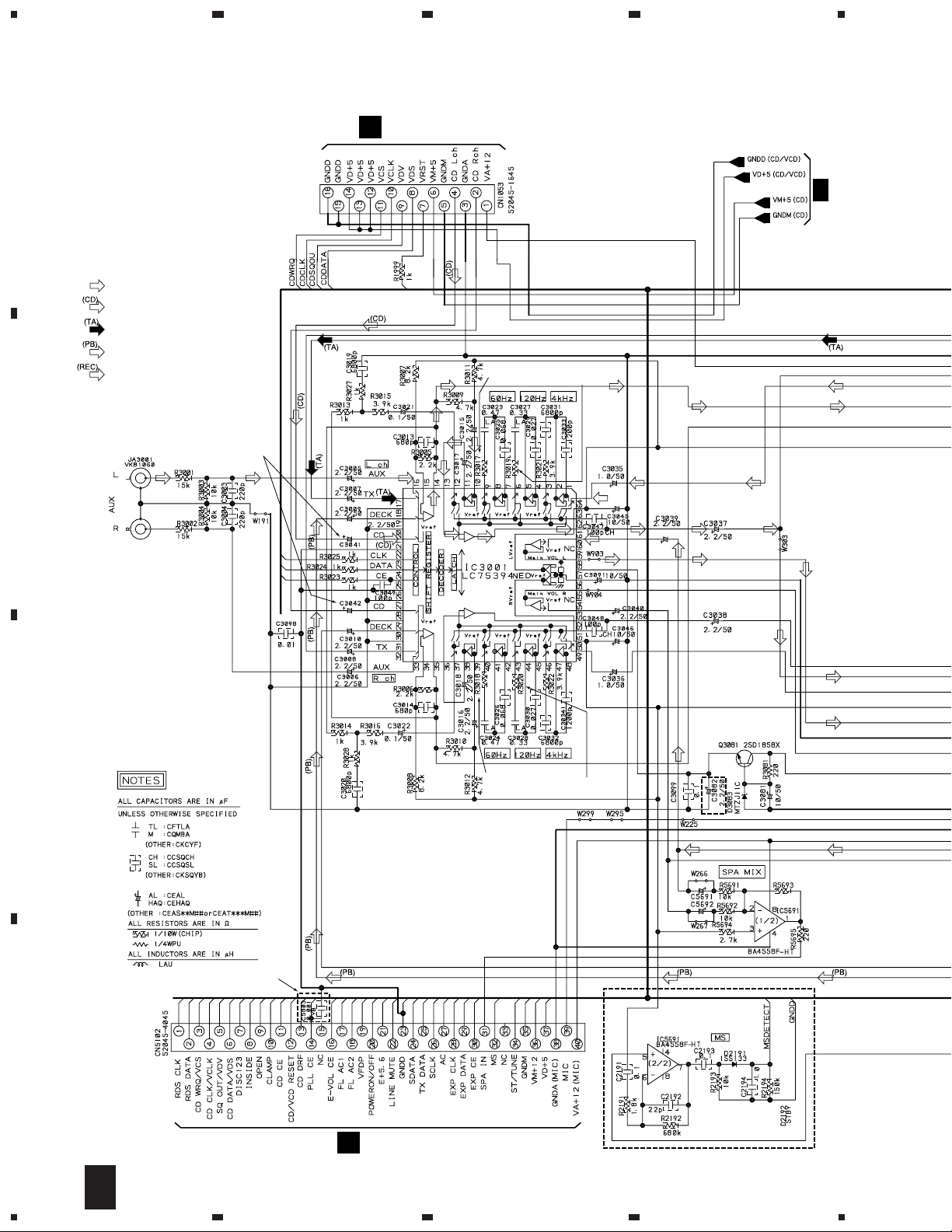
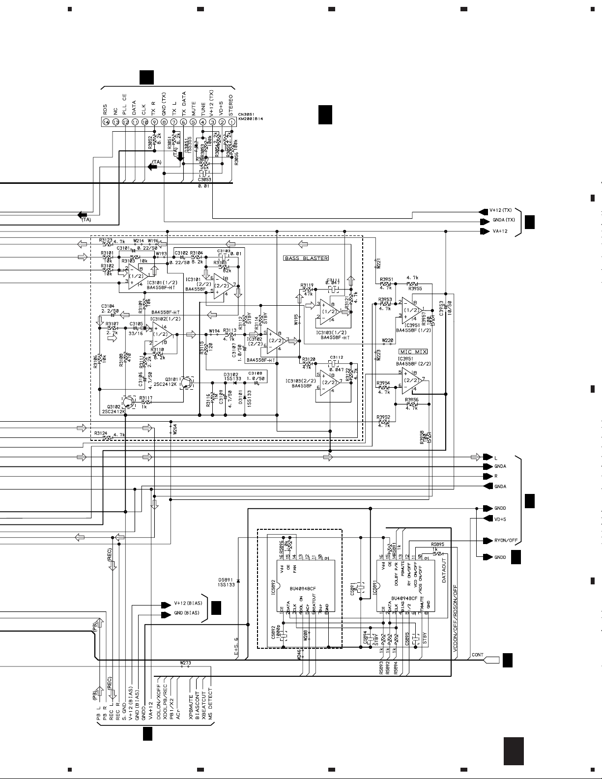
3.4 AF ASSY (1/3)
23
4
A
E
1/3
AF ASSY
(XR-VS77 : XWZ3102)
(XR-VS55 : XWZ3068)
XR-VS77
ONLY
22k(XR-VS77)
39k(XR-VS55)
B
: DECK PB SIGNAL ROUTE
: DECK REC SIGNAL ROUTE
XR-VS55
ONLY
XR-VS77
ONLY
C2335 27p
C2336 27p
XR-VS55
ONLY
C2337 27p
XR-VS55
ONLY
XR-VS77
ONLY
XR-VS55
ONLY
XR-VS77
ONLY
680p(XR-A660)
1000p(XRA550,A330)
C
XR-VS55
ONLY
D
33k(XR-VS77)
47k(XR-VS55)
220k(XR-VS77)
100k(XR-VS55)
XR-VS77
ONLY
0.022(XR-VS77)
0.027(XR-VS55)
C2338 27p
XR-VS55
ONLY
24
1/3
E
1234
Page 25
XR-VS55
ONLY
5
678
XR-VS77, XR-VS55
A
XR-VS55
ONLY
XR-VS55
ONLY
22k(XR-VS77)
1k(XR-VS55)
22k(XR-VS77)
1k(XR-VS55)
XR-VS55
ONLY
XR-VS77 ONLY
XR-VS55
ONLY
E
2/3
E
B
C
2/3
3/3
E
D
2/3
E
XR-VS77
ONLY
1/3
E
5
6
7
8
25
Page 26
1
XR-VS77, XR-VS55
23
4
3.5 AF ASSY (2/3)
A
: AUDIO SIGNAL ROUTE
: CD AUDIO SIGNAL ROUTE
: TUNER AUDIO SIGNAL ROUTE
: DECK PB SIGNAL ROUTE
: DECK REC SIGNAL ROUTE
B
2.2/50(XR-VS77)
0.47/50(XR-VS55)
CN1004
B
6.8k(XR-VS77)
0k(XR-VS55)
6.8k(XR-VS77)
3.9k(XR-VS55)
E
3/3
C
XR-VS77
ONLY
D
CN5501
I
26
2/3
E
1234
6.8k(XR-VS77)
0k(XR-VS55)
6.8k(XR-VS77)
3.9k(XR-VS55)
XR-VS77
ONLY
XR-VS55 ONLY
2.7k(XR-VS77)
56k(XR-VS55)
Page 27
5
A
CN6201
678
XR-VS77, XR-VS55
A
AF ASSY
2/3
E
(XR-VS77 : XWZ3102)
(XR-VS55 : XWZ3068)
3/3
E
XR-VS77 ONLY
B
C
3/3
E
XR-VS77
ONLY
1/3
E
3/3
E
3/3
E
D
1/3
E
2/3
E
5
6
7
8
27
Page 28

1
23
XR-VS77, XR-VS55
3.6 AF (3/3) and SECONDARY ASSEMBLIES
A
2/3
E
B
IC3301
STK407-070B(XR-VS77)
STK407-050B(XR-VS55)
4
2/3
E
1/3
E
C
2/3
E
1/3
E
2/3
D
E
28
2/3
E
3/3
E
1234
Page 29

5
678
XR-VS77, XR-VS55
E
AF ASSY
3/3
(XR-VS77 : XWZ3102)
(XR-VS55 : XWZ3068)
: AUDIO SIGNAL ROUTE
CAUTION : FOR CONTINUED PROTECTION AGAINST
CAUTION : FOR CONTINUED PROTECTION AGAINST
CAUTION : FOR CONTINUED PROTECTION AGAINST
RISK OF FIRE. REPLACE ONLY WITH SAME
TYPE NO. 4911.25 MFD, BY LITTELFUSE INK.
FOR IC71 (AEK7010).
RISK OF FIRE. REPLACE ONLY WITH SAME
TYPE NO. 491003 MFD, BY LITTELFUSE INK.
FOR IC31 AND IC41 (AEK7015).
RISK OF FIRE. REPLACE ONLY WITH SAME
TYPE NO. 491007 MFD, BY LITTELFUSE INK.
FOR IC11 AND IC12 (AEK7021: XR-VS77).
12k(XR-VS77)
15k(XR-VS55)
CAUTION : FOR CONTINUED PROTECTION AGAINST
CAUTION
CAUTION
RISK OF FIRE. REPLACE ONLY WITH SAME
TYPE NO. 491005 MFD, BY LITTELFUSE INK.
FOR IC21 AND IC22 (AEK7046: XR-VS77).
: FOR CONTINUED PROTECTION AGAINST
RISK OF FIRE. REPLACE ONLY WITH SAME
TYPE NO. 491005 MFD, BY LITTELFUSE INK.
FOR IC11 AND IC12
: FOR CONTINUED PROTECTION AGAINST
RISK OF FIRE. REPLACE ONLY WITH SAME
TYPE NO. 491004 MFD, BY LITTELFUSE INK.
FOR IC21 AND IC22
(AEK7019: XR-VS55).
(AEK7053: XR-VS55).
SPEAKER
XR-VS77 ONLY
A
B
2SA965(XR-VS77)
2SA1837(XR-VS55)
5.6k(XR-VS77)
2.2k(XR-VS55)
XR-VS77
ONLY
100/100(XR-VS77)
220/63(XR-VS55)
XR-VS55
ONLY
820(XR-VS77)
1.5k(XR-VS55)
J81
H
3300/50(XR-VS77)
2200/50(XR-VS55)
IC11, IC12
AEK7021(XR-VS77)
AEK7019(XR-VS55)
IC21, IC22
AEK7046(XR-VS77)
AEK7053(XR-VS55)
SECONDARY ASSY
F
(XR-VS77 : XWZ3103)
(XR-VS55 : XWZ3069)
C
T1
POWER TRANSFORMER
D
3/3
E
5
6
7
F
8
29
Page 30

1
23
XR-VS77, XR-VS55
3.7 PRIMARY and SUB TRANS ASSEMBLIES
A
PRIMARY ASSY
G
(XWZ3048)
4
H5 H6
B
XR-VS77 : AEK1057 (T2A)
XR-VS55 : AEK1056 (T1.6A)
POWER TRANSFORMER
C
AKR7001
H3 H4
SUB TRANS ASSY
H
(XWZ3049)
CN81
3/3
E
D
30
G H
1234
Page 31

5
678
XR-VS77, XR-VS55
A
B
10000pF/AC250V
• NOTE FOR FUSE REPLACEMENT
CAUTION -
FOR CONTINUED PROTECTION AGAINST RISK OF FIRE.
REPLACE WITH SAME TYPE AND RATINGS ONLY.
XR-VS77 : AEK1060 (T4A)
XR-VS55 : AEK1059 (T3.15A)
C
D
G H
5
6
7
8
31
Page 32

1
23
XR-VS77, XR-VS55
3.8 DISPLAY and CD SW LED ASSEMBLIES
DISPLAY ASSY
A
I
(XR-VS77 : XWZ3104)
(XR-VS55 : XWZ3070)
4
SLP6118C51H
B
1k(XR-VS77)
0(XR-VS55)
XR-VS77
ONLY
XR-VS77
ONLY
XR-VS55
ONLY
XR-VS77
ONLY
C
XR-VS55
ONLY
D
V5621 FL TUBE
XAV3004(XR-VS77)
XAV3003(XR-VS55)
32
I
1234
Page 33

5
678
XR-VS77, XR-VS55
XR-VS77 ONLY
SLP9118C51H
XR-VS77 ONLY
CN5501
52045-4045
XR-VS77
ONLY
E
2/3
CN5101
1SS183
HLEM19S-1(XR-VS77)
HLEM17S-1(XR-VS55)
A
B
DECK MECH
XR-VS77
ONLY
DISPLAY ASSY
S5911 : DISPLAY
S5912 : TIMER
S5913 : ENTER
S5914 : P. BASS
S5915 : ZOOM SURROUND
S5916 : BASS BLASTER
S5917 : EQUALIZER
S5918 : PRESET
S5919 : STANDBY/ON
S5920 : TUNING - 1 4
S5921 : TUNING + ¡ ¢
S5922 : STOP
S5923 : PLAY/PAUSE
XR-VS55
ONLY
S5924 : REC/STOP
S5925 : FREQ/STATION
S5926 : DOLBY NR ON/OFF
S5927 : ASES/COPY
S5928 : AUX
S5929 : TAPE Ι/ΙΙ
S5930 : TUNER/BAND
S5931 : CD
S5932 : DISC 1 SELECT
S5933 : DISC 2 SELECT
S5934 : DISC 3 SELECT
S5935 : DISC CHANGE
S5936 : OPEN/CLOSE
5
XR-VS77 ONLY
6
CD SW LED ASSY
J
(XWZ3086)
7
XR-VS77 ONLY
XR-VS55
ONLY
S5937 : OPEN/CLOSE
S5938 : DISC CHANGE
S5939 : DISC 3 SELECT
S5940 : DISC 2 SELECT
S5941 : DISC 1 SELECT
JI
8
33
C
D
Page 34

XR-VS77, XR-VS55
4. PCB CONNECTION DIAGRAM
NOTE FOR PCB DIAGRAMS :
1. Part numbers in PCB diagrams match those in the schematic
diagrams.
2. A comparison between the main parts of PCB and schematic
diagrams is shown below.
Symbol In PCB
Diagrams
BCE
BCE
D
Symbol In Schematic
Diagrams
BCEBCE
BCE
DGGSS
BCE
DGS
Part Name
Transistor
Transistor
with resistor
Field effect
transistor
Resistor array
3-terminal
regulator
3. The parts mounted on this PCB include all necessary parts for
several destinations.
For further information for respective destinations, be sure to
check with the schematic diagram.
4. View point of PCB diagrams.
Connector
Capacitor
SIDE A
P.C.Board
Chip Part
SIDE B
34
Page 35

1
4.1 FM/AM TUNER MODULE
FM/AM TUNER MODULE
A
234
XR-VS77, XR-VS55
A
CN3051
E
SIDE A
B
FM/AM TUNER MODULE
A
Q6204
VR6201
Q6203
SIDE B
C
IC6201
1
IC6202
Q6202Q6201
Q6205
2
Q6403
Q6404
Q6303 Q6302Q6301
Q6214
Q6402
Q6401
3
Q6304
Q6306
(ANP7159-B)
A
4
D
35
Page 36

1
23
XR-VS77, XR-VS55
4.2 VCD SURVO, MOTOR, SW and TRADE ASSEMBLIES
4
DB
A
TRADE ASSY
SERVO
MECHANISM
ASSY
DA
SW ASSY
LOADING
MOTOR
MOTOR ASSY
C
M
B
E
CN1053
VCD SURVO ASSY
B
(XNP3011-A)
Q1351
Q1352
Q1353
Q1354
IC1001
C
D
PICKUP
ASSY
SIDE A
IC1401
IC1301
IC1201
Q1101
IC1701
IC1501
IC1752
(XNP3010-A)
36
CB
1234
DA DB
Page 37

1
234
XR-VS77, XR-VS55
A
B
VCD SURVO ASSY
B
IC1754
IC1755
IC1101
IC1751
C
D
(XNP3010-A)
1
2
3
SIDE B
B
4
37
Page 38

1
E
AF ASSY
H
J81
CN6201
A
MECHANISM
UNIT
F
J11
VR2302
VR2802
VR230
VR280
Q2801Q2804Q2803Q3081 Q71
Q3351Q31 IC32 IC51 IC42 Q3352
XR-VS77, XR-VS55
4.3 AF ASSY
A
23
4
B
C
D
38
SIDE A
E
1234
Page 39

5
678
XR-VS77, XR-VS55
1
B
CN1004
I
CN5501
A
B
VR2802
1 IC3301
VR2301
VR2801
VR2303VR2302
IC2301
VR2306
MECHANISM
UNIT
MECHANISM
UNIT
(XNP3008-C)
Q52
Q51
C
D
E
5
6
7
8
39
Page 40

1
1
2
XR-VS77, XR-VS55
A
B
23
E
AF ASSY
4
C
(XNP3008-C)
D
SIDE B
40
E
1234
IC5891 IC2101
IC5892 Q3605 Q3608
Q2802 Q2306 Q2105 Q3601
Q53
IC3301
Q2301 Q2204 Q2203 Q
Q3603 Q2302
Q3314 Q3313 Q3312 Q33
IC2201
Page 41

5
678
XR-VS77, XR-VS55
A
B
IC2101 Q2201Q2202 Q5751 Q5752
2204 Q2203 Q2103 IC5751
IC2201
Q3312 Q3311 Q3351 Q3352
Q3353 Q3354 Q3101 Q3102
IC42 IC51 IC32 Q31
5
IC5691 IC3001
IC3951 IC3101 IC3103
Q2805 Q2807
C
D
E
6
7
8
41
Page 42

1
23
XR-VS77, XR-VS55
4.4 SECONDARY and PRIMARY ASSEMBLIES
A
F
SECONDARY ASSY
B
E
J11
IC71
IC11
IC12
IC21
IC22
4
IC31
IC41
(XNP3008-C)
POWER TRANSFORMER (T1)
C
NL
Y1
H
Y2
(XNP3012-B)
D
G
PRIMARY ASSY
SIDE A
42
F
G
1234
Page 43

1
4.5 SUB TRANS ASSY
234
XR-VS77, XR-VS55
E
CN81
Y2
H
SUB TRANS ASSY
A
B
G
Y1
AC IN
C
LIVE
NEUTRAL
(XNP3012-B)
D
SIDE A
H
1
2
3
4
43
Page 44

1
23
XR-VS77, XR-VS55
4.6 DISPLAY and CD SW LED ASSEMBLIES
A
E
CN5101
MECHANISM
UNIT
B
4
I
DISPLAY
ASSY
C
J
CD SW LED
ASSY
(XNP3012-B)
D
SIDE A
44
I
J
1234
Page 45

Q2903
Q2901
Q2906
Q2908
Q2907
1
I
DISPLAY
ASSY
234
XR-VS77, XR-VS55
A
B
Q5605
IC5601
Q2904
IC5501
Q2910
Q2911
Q5801
Q5502
Q5501
Q5821
IC5631
C
J
CD SW LED
ASSY
Q5606
Q5601
Q5604
IC3901
IC3931
(XNP3012-B)
D
SIDE B
JI
1
2
3
4
45
Page 46

XR-VS77, XR-VS55
Mark No. Description Part No.
5. PCB PARTS LIST
NOTES:
LIST OF HOLE PCB ASSEMBLIES
Parts marked by "NSP" and can not be supplied.
•
The mark found on some component parts indicates the importance of the safety factor of the part.
•
Therefore, when replacing, be sure to use parts of identical designation.
When ordering resistors, first convert resistance values into code form as shown in the following examples.
•
Ex.1 When there are 2 effective digits (any digit apart from 0), such as 560 ohm and 47k ohm (tolerance is shown by J=5%,
and K=10%).
560 Ω→56 × 10
47k Ω→47 × 10
1
→ 561 ........................................................RD1/4PU 5 6 1 J
3
→ 473 ........................................................RD1/4PU 4 7 3 J
0.5 Ω→R50 .....................................................................................RN2H
1 Ω→1R0 ..................................................................................... RS1P 1 R 0 K
Ex.2 When there are 3 effective digits (such as in high precision metal film resistors).
5.62k Ω→ 562 × 10
1
→ 5621 ...................................................... RN1/4PC 5 6 2 1 F
kraMnoitpircseDdnalobmyS
ELUDOMRENUTMA/MF
YSSAOBRUSDCV
PSN
YSSAWS
PSN
YSSABCPAHCEMM$
YSSAROTOM
YSSAEDART
Mark No. Description Part No.
R 5 0
K
.oNtraP
77SV-RX55SV-RX
,JXDBD
CN/JXLD
5607QXA
3003XWX
4003XWX
0803ZWX
1803ZWX
2803ZWX
,JXDBD
CN/JXLD
5607QXA
3003XWX
4003XWX
0803ZWX
1803ZWX
2803ZWX
skrameR
PSN
PSN
YSSANIAM
YSSAFA
YSSAYRADNOCES
YSSAXELPMOC
YSSAYRAMIRP
YSSASNARTBUS
YSSAYALPSID
YSSADELWSDC
Mark No. Description Part No.
FM/AM TUNER MODULE
A
SEMICONDUCTORS
IC6201 LA1832ML
IC6202 LC72131MD
Q6402 2SC2223
Q6203 2SC2705
Q6201, Q6202 2SC2712
Q6214, Q6403 2SC2714
Q6404 2SK302
Q6401 3SK194
Q6204 DTA124ES
Q6205 DTC124EK
D6202 1SS254
D6401, D6402 1T378A
COILS AND FILTERS
L6404 FM COIL ATC1003
L6401 FM RF COIL ATC1020
L6402 FM RF COIL ATC1021
F6204 FM CERAMIC FILTER ATF–107
F6203 FM CERAMIC FILTER ATF–119
7503MWX
2013ZWX
3013ZWX
8503MWX
8403ZWX
9403ZWX
4013ZWX
6803ZWX
0403MWX
8603ZWX
9603ZWX
1403MWX
8403ZWX
9403ZWX
0703ZWX
desutoN
Mark No. Description Part No.
F6401 FM BAND PASS FILTER ATF–155
F6206 FM CERAMIC DISCRIMINATOR ATF7008
F6202 AM CERAMIC FILTER ATF7011
L6206, L6208, L6403 LAU2R2J
TRANSFORMERS
T6201 AM IF TRANS. ATB7008
T6401 FM CONNECT TRANS. ATE7002
CAPACITORS
C6208 CCSQCH100D50
C6212, C6274, C6275, C6408 CCSQCH101J50
C6412 CCSQCH102J50
C6221, C6222, C6416 CCSQCH150J50
C6271 CCSQCH200J50
C6415 CCSQCH330J50
C6406 CCSQCH331J50
C6401, C6419 CCSQCH5R0C50
C6407 CCSQCK1R0C50
C6410 CCSQCK2R0C50
46
Page 47

XR-VS77, XR-VS55
Mark No. Description Part No.
C6413 CCSQRH180J50
C6414 CCSQRH8R0D50
C6405 CCSQTH150J50
C6234, C6235 CEAL1R0M50
C6245 CEAL470M16
C6224 CEAT100M50
C6243 CEAT101M16
C6231 CEAT1R0M50
C6227 CEAT220M25
C6214, C6236 CEAT2R2M50
C6262 CEAT3R3M50
C6219 CEAT470M10
C6244 CEAT470M16
C6249, C6250, C6265, C6266 CEAT4R7M50
C6258 CEJA470M16
C6215 CFTLA103J50
C6211, C6254, C6403, C6417 CKSQYB102K50
C6201, C6205, C6210, C6237, C6276 CKSQYB103K50
C6278, C6280, C6281, C6402, C6409 CKSQYB103K50
C6418 CKSQYB103K50
C6251, C6252 CKSQYB153K50
C6203, C6259 CKSQYB223K50
C6228 CKSQYB472K50
C6209 CKSQYB473K50
C6230 CKSQYB821K50
C6218, C6223, C6255 CKSQYF103Z50
C6220, C6226, C6242, C6256 CKSQYF223Z50
C6225 CKSQYF473Z50
RESISTORS
R6280 RD1/4PU101J
R6413, R6416, R6418, R6906, R6909 RS1/8S0R0J
R6401 RS1/8S470J
VR6201 (10kΩ) PCP1029
Other Resistors RS1/10S J
OTHERS
BN6202 4P ANTENNA TERMINAL AKE7025
X6202 CERAMIC RESONATOR ASS1066
(456kHz)
X6201 CRYSTAL RESONATOR ASS1093
(7.2000MHz)
Mark No. Description Part No.
COILS AND FILTERS
F1501 DTF1064
F1201 DTF1066
F1202 DTF1067
F1705, F1706 DTF1069
L1702 LCTB1R8K2125
L1701 LCTB2R7K2125
L1201 LFA100J
L1001 LFA220J
CAPACITORS
C1129, C1205, C1208, C1213, C1353 CCSQCH101J50
C1706, C1722 CCSQCH101J50
C1133, C1755, C1756 CCSQCH120J50
C1720 CCSQCH121J50
C1216 CCSQCH150J50
C1708 CCSQCH151J50
C1217 CCSQCH180J50
C1705 CCSQCH271J50
C1132 CCSQCH300J50
C1707 CCSQCH331J50
C1130 CCSQCH3R0C50
C1715, C1717 CCSQCH470J50
C1138 CEAT100M50
C1003, C1108, C1144, C1207, C1214 CEAT101M10
C1301, C1351, C1501 CEAT101M10
C1127 CEAT1R0M50
C1005, C1007, C1126, C1141, C1409 CEAT470M16
C1411 CEAT470M16
C1718 CEAT471M6R3
C1136 CEAT4R7M50
C1109 CEATR22M50
C1124 CEATR47M50
C1101 CEJA3R3M50
C1105 CEJA470M10
C1106, C1119, C1134 CKSQYB102K50
C1102, C1122, C1123, C1139, C1140 CKSQYB103K50
C1209, C1215, C1218, C1231, C1302 CKSQYB103K50
C1354, C1502–C1506, C1703, C9002 CKSQYB103K50
C9005, C9013, C9015 CKSQYB103K50
C1001, C1002, C1004, C1008, C1135 CKSQYB104K25
CN6201 14P SOCKET KP200IA14L
VCD SURVO ASSY
B
MW RF TUNING BLOCK AXX7041
SEMICONDUCTORS
IC1001 BA033FP
IC1401 BA4558F–HT
IC1301 BA5923FP
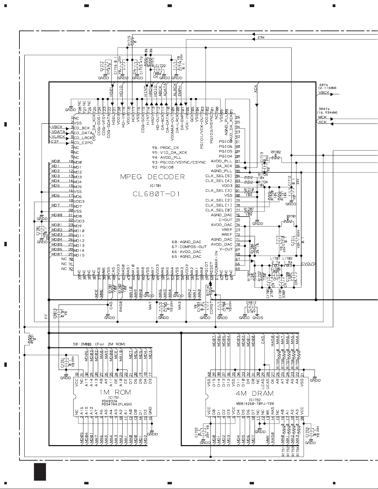
IC1701 CL680T–D1
IC1101 LA9240ML
IC1201 LC78632RE
IC1752 MB814260–70PJ
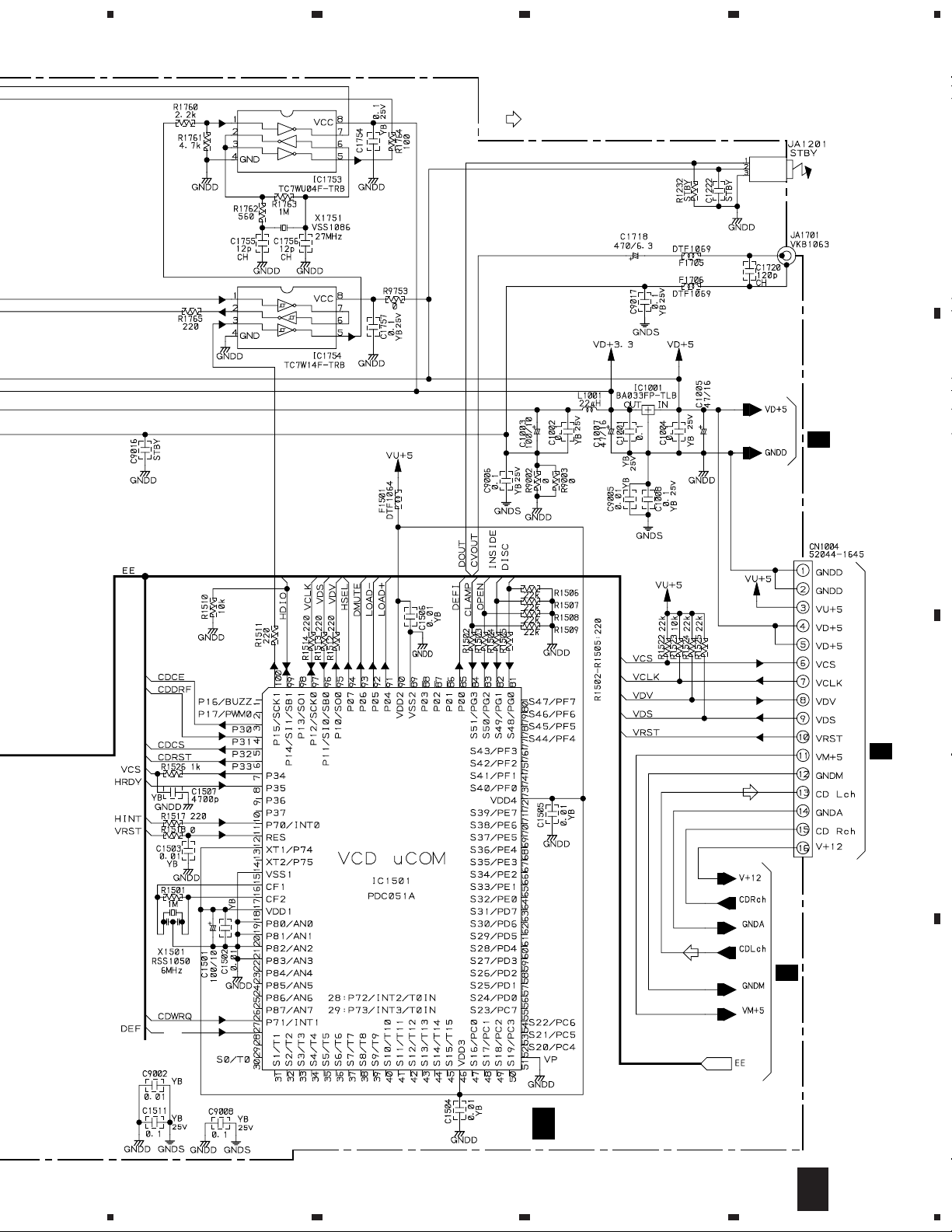
IC1501 PDC051A
IC1751 PDK032A
IC1754 TC7W14F
IC1753 TC7WU04F
Q1101 2SA1048
Q1351, Q1352 2SB1237X
Q1353, Q1354 2SD1858X
D1351–D1354 1SS355
C1151, C1202, C1203, C1511 CKSQYB104K25
C1701, C1702, C1704, C1710–C1714 CKSQYB104K25
C1716, C1751–C1754, C1757, C9004 CKSQYB104K25
C9006, C9008, C9017, C9019 CKSQYB104K25
C1405, C1406 CKSQYB152K50
C1111 CKSQYB153K25
C1114, C1117, C1120, C1121 CKSQYB154K16
C1125 CKSQYB221K50
C1131 CKSQYB222K50
C1107 CKSQYB223K50
C1110, C1403, C1404, C1407, C1408 CKSQYB331K50
C1115, C1128 CKSQYB332K50
C1113 CKSQYB333K25
C1112, C1143 CKSQYB334K16
C1212 CKSQYB471K50
C1507 CKSQYB472K50
C1116, C1142 CKSQYB473K50
C1401, C1402 CKSQYB561K50
C1118, C1201, C1204, C1206 CKSQYF104Z25
47
Page 48

XR-VS77, XR-VS55
Mark No. Description Part No.
RESISTORS
R1704 RS1/10S2001F
Other Resistors RS1/10S J
OTHERS
CN1004 16P FFC CONNECTOR 52044–1645
CN1003 3P SIDE POST B3P–SHF–1AA
CN1002 13P FFC CONNECTOR SLW13R–1C7
CN1001 15P FFC CONNECTOR SLW15R–1C7
JA1701 1P PIN JACK VKB1063
X1201 CRYSTAL RESONATOR PSS1008
X1501 CERAMIC RESONATOR RSS1050
X1751 CRYSTAL RESONATOR VSS1086
MOTOR ASSY
C
(16.9344MHz)
(6MHz)
(27MHz)
SWITCHES AND RELAYS
S9503 ASG7009
OTHERS
J9502 JUMPER WIRE 4P D20PWW0405E
MOTOR PULLEY PNW1634
CARRIAGE MOTOR VXM1033
Mark No. Description Part No.
Q3081 2SD1858X
Q31 2SD2012
Q2203, Q2204, Q2805, Q3311, Q3312 2SD2114K
Q2301, Q2302 2SK368
Q3313 DTA124EK
Q2104, Q2105, Q3314 DTC124EK
Q2103, Q2306, Q2802 DTC143EK
Q3351 IRFI9Z34G
Q3352 IRFIZ34G
D3301, D3302 1SR139–100
D2191, D2301–D2306, D3101, D3102 1SS133
D3351–D3354, D3361, D3362, D3601 1SS133
D3603, D3604, D3621, D3622 1SS133
D3625, D3626, D5891, D73 1SS133
D2102, D2103, D2201, D2202, D3051 1SS355
D3355, D3356 20E2–FC
D3357, D3358 MTZJ10C
D3083 MTZJ11C
D35, D36 MTZJ15C
D3359, D3360 MTZJ18B
D74 MTZJ33C
D3363, D3364 MTZJ39C
D2001 MTZJ6.2A
D48, D53 MTZJ6.8C
D75 MTZJ8.2B
D71, D72 S5688G
SW ASSY
DA
SWITCHES AND RELAYS
S9502 ASG7009
S9501 DSG1017
OTHERS
J9501 JUMPER WIRE 6P D20PWY0610E
TRADE ASSY
DB
OTHERS
CN9501 52147–0610
CN9001 S6B–PH–K–S
CN9002 SLW13R–1C7
AF ASSY (XWZ3102)
E
SEMICONDUCTORS
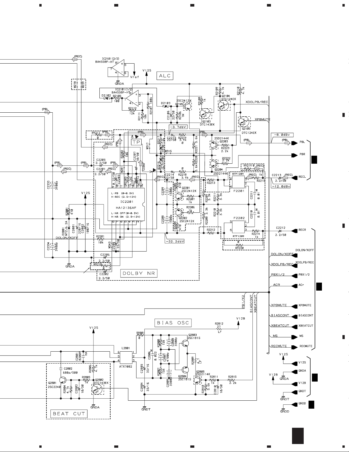
IC2101, IC3101–IC3103, IC3951 BA4558F–HT
IC5691 BA4558F–HT
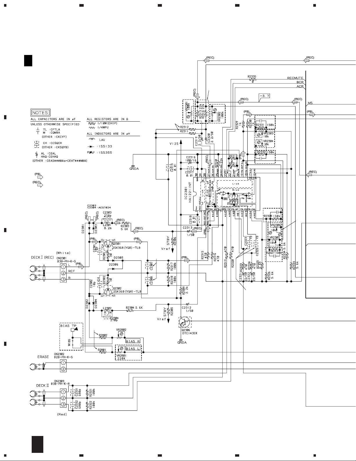
IC5891, IC5892 BU4094BCF
IC2201 HA12136AF
IC2301 HA12211NT
IC3001 LC75394NED
IC42, IC51 NJM7805FA
IC32 NJM7812FA
IC3301 STK407–070B
Q71 2SA965
Q3354, Q3601, Q3621 2SA1037K
Q51, Q52 2SB1237X
Q2803, Q2804 2SC1815
Q2801 2SC2240
Q2102, Q2201, Q2202, Q3101, Q3102 2SC2412K
Q3353, Q3603, Q3605–Q3608, Q53 2SC2412K
COILS AND FILTERS
L3331, L3332 ATH–133
L2801 ATX7002
L3991 LAU4R7J
L2301, L2302 LTA822J
F2201, F2202 RTF1209
SWITCHES AND RELAYS
RY3601 ASR7008
CAPACITORS
C2303, C2304 (270pF) ACG7024
C2301, C2302 CCSQCH100D50
C3047, C3048 CCSQCH101J50
C2192 CCSQCH220J50
C3319, C3320 CCSQCH3R0C50
C3317, C3318 CEANP220M35
C3621 CEANP2R2M2A
C3313, C3314 CEANP2R2M50
C2207, C2803, C2810, C3045, C3046 CEAT100M50
C3081, C3091, C33, C35, C3602 CEAT100M50
C3953, C43, C52 CEAT100M50
C2002, C2316 CEAT101M16
C71 CEAT101M2A
C3303, C3304 CEAT101M50
C2312, C2313, C3035, C3036 CEAT1R0M50
C3107, C3108, C32, C3311, C3312 CEAT1R0M50
C42 CEAT1R0M50
C2106, C2214, C2215, C2321, C2322 CEAT220M50
C53, C72 CEAT220M50
C2001, C3601 CEAT221M16
C41 CEAT222M25
C31 CEAT222M35
C2201, C2202, C2205, C2206 CEAT2R2M50
C2212, C2213, C2319, C2320 CEAT2R2M50
C3005–C3010, C3015–C3018 CEAT2R2M50
48
Page 49

XR-VS77, XR-VS55
Mark No. Description Part No.
C3037–C3042, C3104 CEAT2R2M50
C2804, C2805, C3105 CEAT330M16
C3106, C3109 CEAT4R7M50
C3021, C3022 CEATR10M50
C2203, C2204, C3101, C3102 CEATR22M50
C3325 CEATR47M50
C3027, C3028 CFTLA334J50
C3023, C3024 CFTLA474J50
C2802 CKCYB681K2H
C5892 CKSQYB102K50
C1992, C1993, C2315, C2317, C2318 CKSQYB103K50
C3053, C3098, C3103 CKSQYB103K50
C2191, C2193, C3099, C5891 CKSQYB104K25
C2194 CKSQYB105K10
C3033, C3034 CKSQYB122K50
C2208, C2209 CKSQYB152K50
C3315, C3316 CKSQYB222K50
C2323, C2326 CKSQYB223K50
C3029, C3030 CKSQYB273K50
C2808, C2809 CKSQYB332K50
C2333, C2334 CKSQYB392K50
C2807 CKSQYB472K50
C3111, C3112 CKSQYB473K25
C2307, C2308, C2331, C2332 CKSQYB681K50
C3013, C3014 CKSQYB681K50
C3019, C3020, C3031, C3032 CKSQYB682K50
C3025, C3026 CKSQYB683K25
C3331–C3333 CKSQYF104Z50
C2801 CQHA822J2A
C2210, C2211 CQMBA103J50
C2806 CQMBA223J50
RESISTORS
R2812 RD1/2LMF270J
R2809 RD1/2LMF4R7J
R54 RD1/2PM181J
R52 RD1/2PM221J
R72 RD1/2PM562J
R3333, R3334 RD1/4LMF100J
R3353, R3354 RD1/4PU101J
R73 RD1/4PU103J
R3081 RD1/4PU221J
R3317, R3318 RD1/4PU683J
Mark No. Description Part No.
AF ASSY (XWZ3068)
E
SEMICONDUCTORS
IC2101, IC3951, IC5691 BA4558F–HT
IC5891 BU4094BCF
IC2301 HA12211NT
IC42, IC51 NJM7805FA
IC32 NJM7812FA
IC3301 STK407–050B
Q71 2SA1837
Q31 2SD2012
Q3351 IRFI9Z34G
Q3352 IRFIZ34G
D3301, D3302 1SR139–100
D3355, D3356 20E2–FC
D72, D76 S5688G
IC3001 LC75394NED
Q3354, Q3601, Q3621 2SA1037K
Q51, Q52 2SB1237X
Q2803, Q2804 2SC1815
Q2102, Q2201, Q2202, Q3353, Q3603 2SC2412K
Q3605–Q3608, Q53 2SC2412K
Q3081 2SD1858X
Q2203, Q2204, Q2805, Q3311, Q3312 2SD2114K
Q2301, Q2302 2SK368
Q3313 DTA124EK
Q2104, Q2105, Q3314 DTC124EK
Q2103, Q2306 DTC143EK
D2301–D2306, D3351–D3354 1SS133
D3361, D3362, D3601, D3603, D3604 1SS133
D3621, D3622, D3625, D3626, D5891 1SS133
D73 1SS133
D2102, D2103, D3051 1SS355
D3357, D3358 MTZJ10C
D3083 MTZJ11C
D35, D36 MTZJ15C
D3359, D3360 MTZJ18B
D74 MTZJ33C
D3363, D3364 MTZJ39C
D2001 MTZJ6.2A
D48, D53 MTZJ6.8C
D75 MTZJ8.2B
R3991, R3992 RS2LMF331J
R3601, R3602 RS3LMFR22J
VR2303–VR2306 (10kΩ) VCP1156
VR2301, VR2302 (100kΩ) VCP1162
VR2801, VR2802 (220kΩ) VCP1164
Other Resistors RS1/10S J
OTHERS
15P CABLE HOLDER 51063–1505
CN1053 16P FFC CONNECTOR 52045–1645
CN5101 40P FFC CONNECTOR 52045–4045
CN81 4P JUMPER CONNECTOR 52147–0410
CN3331 4P SPEAKER TERMINAL AKE7001
CN2302 KR CONNECTOR B2B–PH–K–S
CN2303 KR CONNECTOR B3B–PH–K–R
CN2301 KR CONNECTOR 3P B3B–PH–K–S
CN3051 14P PLUG KM200IB14
JA3001, JA3441 2P PIN JACK VKB1060
CN3991 HEADPHONE JACK XKN3001
COILS AND FILTERS
L3331, L3332 ATH–133
L2801 ATX7002
L3991 LAU4R7J
L2301, L2302 LTA822J
SWITCHES AND RELAYS
RY3601 ASR7008
CAPACITORS
C2303, C2304 (270pF) ACG7024
C2335–C2338 CCCCH270J50
C2301, C2302 CCSQCH100D50
C3047–C3049 CCSQCH101J50
C3319, C3320 CCSQCH3R0C50
C3317, C3318 CEANP220M35
C3621 CEANP2R2M2A
C3313, C3314 CEANP2R2M50
C73 CEAT100M2A
C2810, C3045, C3046, C3081, C3091 CEAT100M50
49
Page 50

XR-VS77, XR-VS55
Mark No. Description Part No.
C33, C35, C3602, C3953, C43 CEAT100M50
C52 CEAT100M50
C2002, C2316 CEAT101M16
C3303, C3304 CEAT101M50
C2312, C2313, C32, C3311, C3312 CEAT1R0M50
C42 CEAT1R0M50
C2106, C2214, C2215, C2321, C2322 CEAT220M50
C53, C72 CEAT220M50
C2001, C3601 CEAT221M16
C71 CEAT221M63
C41 CEAT222M25
C31 CEAT222M35
C2212, C2213, C2319, C2320 CEAT2R2M50
C3005–C3010, C3015–C3018 CEAT2R2M50
C3037–C3040, C3082 CEAT2R2M50
C2804, C2805 CEAT330M16
C3021, C3022 CEATR10M50
C3041, C3042, C3325 CEATR47M50
C3027, C3028 CFTLA334J50
C3023, C3024 CFTLA474J50
C2307, C2308 CKSQYB102K50
C1992, C1993, C2315, C2317, C2318 CKSQYB103K50
C3053, C3098 CKSQYB103K50
C3099, C5891 CKSQYB104K25
C3033, C3034 CKSQYB122K50
C3315, C3316 CKSQYB222K50
C2323, C2326, C3029, C3030 CKSQYB273K50
C2808, C2809 CKSQYB332K50
C2333, C2334 CKSQYB392K50
C2807 CKSQYB472K50
C2331, C2332, C3013, C3014 CKSQYB681K50
C3019, C3020, C3031, C3032 CKSQYB682K50
C3025, C3026 CKSQYB683K25
C3331–C3333 CKSQYF104Z50
C2801 CQHA822J2A
C2806 CQMBA223J50
RESISTORS
R2812 RD1/2LMF270J
R2809 RD1/2LMF4R7J
R54 RD1/2PM181J
R52 RD1/2PM221J
R72 RD1/2PM222J
R3333, R3334 RD1/4LMF100J
R3353, R3354 RD1/4PU101J
R2113, R73 RD1/4PU103J
R3081 RD1/4PU221J
R3317, R3318 RD1/4PU683J
R3991, R3992 RS2LMF331J
R3601, R3602 RS2LMFR22J
VR2802 (100kΩ) VCP1162
Other Resistors RS1/10S J
Mark No. Description Part No.
CN3991 HEADPHONE JACK XKN3001
SECONDARY ASSY
F
(1) CONTRAST TABLE
XWZ3069 and XWZ3103 are constructed the same except
for the following :
Mark Symbol and Description
IC11,IC12 PROTECTOR AEK7021 AEK7019
IC21,IC22 PROTECTOR AEK7046 AEK7053
C21,C22 CEAT332M50 CEAT222M50
Part No.
XWZ3103 XWZ3069
(7A) (5A)
(5A) (4A)
Remarks
(2) PARTS LIST FOR XWZ3103
SEMICONDUCTORS
IC71 (1.25A) AEK7010
IC31, IC41 (3A) AEK7015
IC11, IC12 (7A) AEK7021
IC21, IC22 (5A) AEK7046
D11, D21 GBU4DL–5303
D41–D44 S5566G(TPB2)
D31–D34 S5688G
CAPACITORS
C11, C12 (220µF/63V) ACH7071
C21, C22 CEAT332M50
OTHERS
J11 JUMPER WIRE D15A15–350–2651
PRIMARY ASSY
G
15P CABLE HOLDER 51063–1505
SWITCH
S1 AKX7006
CAPACITOR
C3 (10000pF/AC250V) ACG7020
OTHERS
H3–H6 FUSE CLIP AKR7001
SUB TRANS ASSY
H
SEMICONDUCTORS
IC81 NJM7805FA
D81–D84 S5688G
Q81 2SD1859X
D85, D88–D90 1SS133
OTHERS
CN1053 16P FFC CONNECTOR 52045–1645
CN5101 40P FFC CONNECTOR 52045–4045
CN81 4P JUMPER CONNECTOR 52147–0410
CN3331 4P SPEAKER TERMINAL AKE7001
CN2302 KR CONNECTOR B2B–PH–K–S
CN2303 KR CONNECTOR B3B–PH–K–R
CN2301 KR CONNECTOR 3P B3B–PH–K–S
CN3051 14P PLUG KM200IB14
JA3001 2P PIN JACK VKB1060
50
15P CABLE HOLDER 51063–1505
TRANSFORMER
T2 ATT7027
SWITCH AND RELAY
S2 AKX7004
RY81 ASR7018
CAPACITORS
C83 CEAT100M50
C82 CEAT102M25
Page 51

XR-VS77, XR-VS55
Mark No. Description Part No.
RESISTORS
All Resistors RD1/4PU J
OTHERS
AN1 1P AC INLET BKP1046
H1, H2 FUSE CLIP AKR7001
J81 JUMPER WIRE 4P D20PYY0425E
DISPLAY ASSY (XWZ3104)
I
4P CABLE HOLDER 51048–0400
SEMICONDUCTORS
IC5631 BA3835F
IC3901 BA4558F–HT
IC5601 BU2092F
IC3931 BU9253FS
IC5501 PDC050B
Q5501 2SA1037K
Q2903, Q2906, Q2908 2SB1132
Q5604, Q5801 2SC2412K
Q2910, Q2911 DTA124EK
Q5606 DTC124EK
Q2901, Q2904, Q2907, Q5502, Q5603 DTC143EK
Q5821 DTC143EK
D5591, D5593, D5811 1SS133
D5563–D5568 1SS181
D2901–D2903, D5569, D5570, D5626 1SS355
D5901 1SS355
D5612 BR5064X
D5613–D5616 MAA5064X
D5608–D5611 MBG5064X
D3931 MTZJ5.1B
Mark No. Description Part No.
C3939 CKSQYB123K50
C5509, C5951–C5954 CKSQYB471K50
C3907, C3938, C5506–C5508 CKSQYB472K50
C3935 CKSQYB473K50
C3942, C5602, C5631–C5634, C5901 CKSQYF104Z50
C5503, C5504, C5813, C5822 CKSQYF473Z50
RESISTORS
R5529 (470Ω) ACN7056
R5561, R5562 (1.5kΩ) ACN7062
R5563, R5564 (47kΩ) ACN7077
R5508 RA11T104J
R5506 RA7T104J
R2907, R2909, R2910, R5611, R5919 RD1/4PU102J
R5915 RD1/4PU181J
R5925 RD1/4PU331J
R3940 RD1/4PU471J
R5605, R5606, R5612, R5613, R5926 RD1/4PU561J
R2902, R5604, R5607–R5610 RD1/4PU681J
R5927 RD1/4PU821J
R2911–R2913, R5567 RS1/8S0R0J
R5702 RS1/8S223J
R5614 RS1/8S331J
R2905 RS1/8S681J
VR3901, VR3931 XCS3002
Other Resistors RS1/10S J
OTHERS
CN2901 19P FFC CONNECTOR 52045–1945
CN5501 40P FFC CONNECTOR 52045–4045
JA3901, JA3902 JACK AKN7004
5901 REMOTE RECEIVER UNIT GP1U28X
V5621 FL TUBE XAV3004
D5617–D5620 SLP6118C51H
D5603–D5607, D5621 SLP9118C51H
COILS AND FILTERS
F3903, F3904 DTF1069
L5811 LAU220J
L3931 LCTB100K2125
SWITCHES AND RELAYS
S5951 ASX7004
S5952 ASX7017
S5911–S5931 XSG3001
CAPACITORS
C5812 (0.047F/5.5V) ACH1246
C3941 CCSQCH101J50
C5601 CCSQSL151J50
C3903 CCSQSL331J50
C5821 CEJA100M16
C3943 CEJA101M16
C5803 CEJA1R0M50
C3933 CEJA220M16
C3901, C3902, C3904, C3906 CEJA2R2M50
C3905, C5510, C5811, C5814 CEJA470M16
C3936, C3937 CEJA4R7M50
C3932 CEJAR47M50
C5804 CKSQYB102K50
C3911, C3931, C3934, C3940 CKSQYB103K50
C3910, C5816, C5997–C5999 CKSQYB104K25
2902 FL HOLDER XNG3008
X5501 CERAMIC RESONATOR RSS1050
DISPLAY ASSY (XWZ3070)
I
(6MHz)
SEMICONDUCTORS
IC3901 BA4558F–HT
IC3931 BU9253FS
IC5501 PDC050B
Q5501 2SA1037K
Q2903, Q2906, Q2908 2SB1132
Q5604, Q5801 2SC2412K
Q2910, Q2911 DTA124EK
Q5606 DTC124EK
Q2901, Q2904, Q2907, Q5502 DTC143EK
Q5601–Q5603, Q5605, Q5821 DTC143EK
D5591, D5631, D5811 1SS133
D5563–D5568 1SS181
D2901–D2903, D5569, D5570, D5626 1SS355
D5901 1SS355
D3931 MTZJ5.1B
D5602 SLP3118C51H
D5601 SLP7118C51H
D5603, D5604, D5621 SLP9118C51H
COILS AND FILTERS
F3903, F3904 DTF1069
L5811 LAU220J
L3931 LCTB100K2125
51
Page 52

XR-VS77, XR-VS55
Mark No. Description Part No.
SWITCHES AND RELAYS
S5951 ASX7004
S5952 ASX7017
S5911–S5915, S5917–S5925 XSG3001
S5927–S5936 XSG3001
CAPACITORS
C5812 (0.047F/5.5V) ACH1246
C3941 CCSQCH101J50
C3903 CCSQSL331J50
C5821 CEJA100M16
C3943 CEJA101M16
C5803 CEJA1R0M50
C3933 CEJA220M16
C3901, C3902, C3904, C3906 CEJA2R2M50
C3905, C5510, C5811, C5814 CEJA470M16
C3936, C3937 CEJA4R7M50
C3932 CEJAR47M50
C5804 CKSQYB102K50
C3911, C3931, C3934, C3940 CKSQYB103K50
C3910, C5816, C5997–C5999 CKSQYB104K25
C3939 CKSQYB123K50
C5509, C5951–C5954 CKSQYB471K50
C3907, C3938, C5506–C5508 CKSQYB472K50
C3935 CKSQYB473K50
C3942, C5634, C5901 CKSQYF104Z50
C5625 CKSQYF224Z25
Mark No. Description Part No.
CD SW LED ASSY
J
SEMICONDUCTORS
D5623 SLP3118C51H
D5624 SLP7118C51H
D5622 SLP9118C51H
SWITCHES
S5937–S5941 XSG3001
RESISTORS
All Resistors RS1/10S J
OTHERS
J5501 JUMPER WIRE D20PWW0615E
C5503, C5504, C5813, C5822 CKSQYF473Z50
RESISTORS
R5529 (470Ω) ACN7056
R5561, R5562 (1.5Ω) ACN7062
R5563, R5564 (47kΩ) ACN7077
R5508 RA11T104J
R5506 RA7T104J
R2907, R2909, R2910, R5919 RD1/4PU102J
R5915 RD1/4PU181J
R5925 RD1/4PU331J
R3940 RD1/4PU471J
R5926 RD1/4PU561J
R2902 RD1/4PU681J
R5927 RD1/4PU821J
R2911–R2913, R5567 RS1/8S0R0J
R5702 RS1/8S223J
R5614 RS1/8S331J
R2905 RS1/8S681J
VR3901, VR3931 XCS3002
Other Resistors RS1/10S J
OTHERS
CN2901 17P FFC CONNECTOR 52045–1745
CN5501 40P FFC CONNECTOR 52045–4045
JA3901, JA3902 JACK AKN7004
5901 REMOTE RECEIVER UNIT GP1U28X
5631 FL HOLDER VNF1096
52
V5621 FL TUBE XAV3003
X5501 CERAMIC RESONATOR RSS1050
(6MHz)
Page 53

6. ADJUSTMENT
6.1 TUNER SECTION
FM Tuner Section
Set the mode selector to FM BAND.
•
Connect the wiring as shown in Fig. 1.
•
petS
.oN
1
2
:etoN
AM Tuner Section
Set the mode selector to AM BAND.
•
Connect the wiring as shown in Fig. 1.
•
petS
.oN
1
(etoN* .zHk0001ebdluohsseicneuqerf,petszHk01gnisuaeraehtroF:)1
tnemtsujdA
eltiT
dnEtnorF
ytivitisneS
.DNIDENUT
leveLgnithgiL
.stnemtsujdaekamneht
tnemtsujdA
eltiT
dnEtnorF
ytivitisneS
)zHM(
8903-0zHM89
8981 ± 2zHM891026RV
)zHk(
(999 * )154-53(zHk999 * )11026T
XR-VS77, XR-VS55
,zHk1(GSMF ± ).vedzHk57
ycneuqerF
ycneuqerF
leveL
Bd( µ )V
).doM%03,zH004(GSMA
leveL
Bd( µ )m/V
noitpeceR
ycneuqerF
yalpsiD
noitpeceR
ycneuqerF
yalpsiD
tnemtsujdA
noitacoL
2046L
1046T
.puthgilot
tnemtsujdA
noitacoL
snoitacificepS
-1026CIehtneewtebegatlovCDehttahtostsujdA
.levelmumixamtasemocebDNGdna02nip
strats.DNIDENUTforotacidniehttahtostsujdA
dna,tsrifrehtohcaehtiwtcatnocotnimehtgnirb,mehtneewtebpagasierehtfI.2046Ldna1046Lneewtebpagonsierehterusekam,gnitsujdaerofeB
snoitacificepS
-1026CIehtneewtebegatlovCDehttahtostsujdA
.levelmumixamtasemocebDNGdna02nip
AM
antenna
terminal
FM
antenna
terminal
AM SG
MPX SG FM SG
FM75Ω antenna terminal
Center
Fig. 1 AM and FM Adjustment Wiring Diagram
FM/AM TUNER MODULE
SIDE A
YELLOW BLACK
AXX7041
60cm
T6401
Center
Loop antenna
AM antenna terminal
PRODUCT
T6201
DC
Voltmeter
IC6201
Pin 20
VR6201
L6401
L6402
Fig. 2 Adjustment Point
53
Page 54

XR-VS77, XR-VS55
6.2 CASSETTE DECK SECTION
6.2.1 For XR-VS77
Adjustment points and test points are shown in Fig.3, Fig.5 and Fig.7.
•
Mechanical Adjustment
Test tape: NCT-111 (3kHz, 30min).
•
1. Tape Speed Adjustment
.oNedoMepaTtseT
1
kceD I
YALP
111-TCN
)zHk3:kcabyalP(
gnitsujdA
stnioP
noRV.JDA
ETTESSAC
)3.giF(AHCEM
AF Assy
tnemerusaeM
stnioP
TSETEPAT
)hcR(TNIOP
)yssAFA(
Front Side
zH0003semoceb ± rettulf&wowtahtmrifnoC.zH02
Tape Speed
ADJ. VR
erudecorPtnemtsujdAskrameR
gnidaerehttahtostsujdadnaWSYALPehtsserP
mrifnoc,noitceridesreverehtni(%3.0wolebsilevel
zH0003nihtiwsignidaerehttaht ± .)zH06
Cassette
Mechanism
Section
(Side View)
Fig.3 Tape Speed ADJ. Point
Electrical Adjustment
Check the following before starting.
(1) Confirm that the tape speed adjustment has been completed.
(2) Clean the heads and demagnetize them using a head eraser.
(3) Set the measurement level to 0 dBV = 1 Vrms.
(4) Use the specified tape for adjustment. Use the labeled (A)
side of the test tape.
STD-331E : For playback check
STD-632 : Normal blank tape
(5) Provide yourself with the following measuring devides:
AC millivoltmeter
•
Low-frequency oscillator
•
Attenuator
•
Oscilloscope
•
(6) Adjust both right and left channels unless otherwise specified.
(7) Turn the DOLBY NR switch off unless otherwize specified.
(8) Warm up the unit for several minutes before adjustment.
In particular, be sure to warm up the unit in the REC/PLAY
mode for 3 to 5 minutes before starting recording/playback
frequency characteristics adjustment.
(9) Always follow the indicated adjustment order.
Otherwise, a complete adjustment may not be achieved.
Playback Adjustment (Decks I and II)
(1) Head Azimuth Adjustment
(2) Playback Level Adjustment
Recording Adjustment (Deck I)
(1) Bias Oscillation Frequency Adjustment
(2) Recording Bias Adjustment
(3) Recording Level Adjustment.
(4) ALC Operation Check
* As the reference recording level is 250nwb/m for STD-331E, the
recording level will be higher by 4 dB for STD-331B (160nwb/m).
When adjusting, pay carefull attention to the type of tape used.
Dolby noise reduction manufactured under license from Dolby
Laboratories Licensing Corporation.
“DOLBY” and the double-D symbol are trademarks of Dolby
Laboratories Licensing Corporation.
54
Page 55

0 dB
30s
315Hz
0 dB: 315 Hz, 250 nwb/m
30s 30s 30s 10s 10s ......................................................................................................... 10s
12.5
6.3kHz 10kHz 315Hz 14kHz
kHz
10kHz
8kHz 4kHz 2kHz
Fig. 4 STD-331E Test Tape
Playback Adjustment
(1) Head Azimuth Adjustment
Do not switch between forward and reverse operation with the screwdriver inserted.
•
petSedoM
1YALP
)Bd02-
/langiStupnI
epaTtseT
epattsetE133-DTS
,zHk01:kcabyalP(
kceD I
kceD II
stnioPgnitsujdA
htumizadaeH
tnemtsujda
)5.giF(wercs
6.3
kHz
stnioP
)yssAFA(
XR-VS77, XR-VS55
500Hz250Hz125
1kHz
tnemerusaeM
TSETEPAT
)hcR,L(TNIOP
tnemtsujdA
eulaV
kcabyalp.xaM
levellangis
Hz
63Hz 40Hz
skrameR
–20 dB
otdnobnocilisylppa,tnemtsujdaretfA
.wercstnemtsujdahtumizadaeheht
(2) Playback Level Adjustment
Since this adjustment determines playback Dolby NR level, perform it carefully.
•
petSedoM
1YALP
E133-DTS
epattset
/langiStupnI
epaTtseT
kceD I
)Bd0,zH513:kcabyalP(
kceD II
stnioPgnitsujdA
)hcL(3032RV
)hcR(4032RV
)hcL(5032RV
)hcR(6032RV
tnemerusaeM
stnioP
TSETEPAT
)hcR,L(TNIOP
)yssAFA(
tnemtsujdA
eulaV
VBd7.3–
skrameR
PLAY BACK
250
3dB
10k
3dB 4dB
12.5k
RECORDING
250
3dB
10k
3dB 5dB
12.5k
REV Azimuth Adjustment Screw
Fig. 5 Head Azimuth Adjustment Screw
FWD Azimuth Adjustment Screw
Fig. 6 Frequency Characteristics
55
Page 56

XR-VS77, XR-VS55
Recording Adjustment
(1) Bias Oscillation Frequency Adjustment
petSedoM
1CER
/langiStupnI
epaTtseT
236-DTSehtdaoL
ehttesdnaepattset
.edomgnidrocer
kceD II
KCED I
stnioPgnitsujdA
1082L
)yssAFA(
(2) Recording Bias Adjustment
Since this adjustment affects recording bias, prevent distortion from increasing due to underbias.
•
petSedoMepaTtseT/langiStupnIstnioPgnitsujdA
dnaepattset236-DTSehtdaoL
kceD II
KCED I levellangistupnI
kceD II
KCED I
1CER
2
CER →
YALP
.XUAotrotceles
.slangiszHk01
ehtotlangiszH513atupnI
tupniehttesdnalanimretXUA
dnazH513ehtkcabyalp/drocer
)wolebetoNehtees(
Note : Set the 10kHz input signal level to the same value as the 315Hz input signal level of step 1.
tnemerusaeM
stnioP
A
neewteB
7.giFnitniop
± .zHk2
.DNGdna
)hcL(1082RV
)hcR(2082RV
eulaV
noitallicsO
stnioP
TSETEPAT
)yssAFA(
TSETEPAT
)yssAFA(
tnemtsujdA
otycneuqerf
zHk0.501eb
.zHk3ot2
tnemerusaeM
)hcR,L(TNIOP
)hcR,L(TNIOP
skrameR
ruofrofnottubPOTS/CERehtfI
DNATSnisirewopehtelihwsdnoces
esaercedlliwycneuqerfeht,edomYB
eulaVtnemtsujdAskrameR
VBd7.32–
levelkcabyalplitnutnemtsujdataepeR
0nihtiwsilangiszHk01ehtfo ± Bd5.0
.langiszH513ehtfotahtmorf
(3) Recording Level Adjustment
petSedoMepaTtseT/langiStupnIstnioPgnitsujdA
1CER
2
CER →
YALP
.XUAotrotceles
.langis
ehtotlangiszH513atupnI
tupniehttesdnalanimretXUA
dnaepattset236-DTSehtdaoL
zH513ehtkcabyalp/drocer
(4) ALC Operation Check
petSedoMepaTtseT/langiStupnIstnioPgnitsujdA
1
2
/CER
ESUAP
.XUAotrotceles
ehtotlangiszH513atupnI
tupniehttesdnalanimretXUA
kceD II
KCED I
kceD II
KCED I
tnemerusaeM
stnioP
levellangistupnI
)hcL(1032RV
)hcR(2032RV
levellangistupnI
ehtevodaBd01+levelaotteS
.1petstaleveltupni
TSETEPAT
)hcR,L(TNIOP
)yssAFA(
TSETEPAT
)hcR,L(TNIOP
)yssAFA(
tnemerusaeM
stnioP
TSETEPAT
TNIOP
)hcR,L(
)yssAFA(
VBd2.8–
2.2– ± .VBd5.2
eulaVtnemtsujdAskrameR
VBd7.7–
dnakcabyalp,gnidrocertaepeR
ehtfolevelkcabyalplitnutnemtsujda
.VBd7.7–semoceblangiszH513
eulaVtnemtsujdAskrameR
signidaerehttahtmrifnoC
56
Page 57

XR-VS77, XR-VS55
AF ASSY
SIDE A
L2801
A
VR2302
VR2802
TAPE TEST
POINT
L ch R ch
VR2301
VR2801
VR2303 VR2305
VR2304
VR2306
FRONT
Fig.7 Adjustment and Measurement Points
57
Page 58

XR-VS77, XR-VS55
6.2.2 For XR-VS55
Adjustment points and test points are shown in Fig.8, Fig.10 and Fig.11.
•
Mechanical Adjustment
Test tape: NCT-111 (3kHz, 30min).
•
1. Tape Speed Adjustment
.oNedoMepaTtseT
1
kceD I
YALP
111-TCN
)zHk3:kcabyalP(
gnitsujdA
stnioP
noRV.JDA
ETTESSAC
)8.giF(AHCEM
AF Assy
stnioP
TSETEPAT
)yssAFA(
)hcR(TNIOP
tnemerusaeM
Front Side
erudecorPtnemtsujdAskrameR
gnidaerehttahtostsujdadnaWSYALPehtsserP
zH0003semoceb ± rettulf&wowtahtmrifnoC.zH02
mrifnoc,noitceridesreverehtni(%3.0wolebsilevel
zH0003nihtiwsignidaerehttaht ± .)zH06
Tape Speed
ADJ. VR
Cassette
Mechanism
Section
(Side View)
Fig.8 Tape Speed ADJ. Point
Electrical Adjustment
Check the following before starting.
(1) Confirm that the tape speed adjustment has been completed.
(2) Clean the heads and demagnetize them using a head eraser.
(3) Set the measurement level to 0 dBV = 1 Vrms.
(4) Use the specified tape for adjustment. Use the labeled (A)
side of the test tape.
STD-331E : For playback check
STD-632 : Normal blank tape
(5) Provide yourself with the following measuring devides:
AC voltmeter (Noisemeter : filter off)
•
AC millivoltmeter
•
Low-frequency oscillator
•
Attenuator
•
Oscilloscope
•
(6) Adjust both right and left channels unless otherwise specified.
0 dB
30s
315Hz
0 dB: 315 Hz, 250 nwb/m
30s 30s 30s 10s 10s ......................................................................................................... 10s
6.3kHz 10kHz 315Hz 14kHz
12.5
kHz
(7) Warm up the unit for several minutes before adjustment.
In particular, be sure to warm up the unit in the REC/PLAY
mode for 3 to 5 minutes before starting recording/playback
frequency characteristics adjustment.
(8) Always follow the indicated adjustment order.
Otherwise, a complete adjustment may not be achieved.
Playback Adjustment (Decks I and II)
(1) Head Azimuth Adjustment
Recording Adjustment (Deck I)
(1) Bias Oscillation Frequency Adjustment
(2) Recording Bias Adjustment
* As the reference recording level is 250nwb/m for STD-331E, the
recording level will be higher by 4 dB for STD-331B (160nwb/m).
When adjusting, pay carefull attention to the type of tape used.
10kHz
6.3
8kHz 4kHz 2kHz
kHz
1kHz
500Hz250Hz125
Hz
–20 dB
63Hz 40Hz
58
Fig. 9 STD-331E Test Tape
Page 59

XR-VS77, XR-VS55
REV Azimuth Adjustment Screw
FWD Azimuth Adjustment Screw
Fig. 10 Head Azimuth Adjustment Screw
Playback Adjustment
(1) Head Azimuth Adjustment
Do not switch between forward and reverse operation with the screwdriver inserted.
•
petSedoM
1YALP
)Bd02-
/langiStupnI
epaTtseT
epattsetE133-DTS
,zHk01:kcabyalP(
kceD I
kceD II
stnioPgnitsujdA
htumizadaeH
tnemtsujda
)01.giF(wercs
stnioP
TSETEPAT
)yssAFA(
Recording Adjustment
(1) Bias Oscillation Frequency Adjustment
petSedoM
1CER
/langiStupnI
epaTtseT
236-DTSehtdaoL
ehttesdnaepattset
.edomgnidrocer
kceD II
KCED I
stnioPgnitsujdA
1082L
)yssAFA(
stnioP
A
neewteB
.DNGdna
tnemerusaeM
)hcR,L(TNIOP
tnemerusaeM
11.giFnitniop
± .zHk2
tnemtsujdA
eulaV
kcabyalp.xaM
levellangis
tnemtsujdA
eulaV
noitallicsO
otycneuqerf
zHk0.501eb
skrameR
otdnobnocilisylppa,tnemtsujdaretfA
.wercstnemtsujdahtumizadaeheht
skrameR
(2) Recording Bias Adjustment
Since this adjustment affects recording bias, prevent distortion from increasing due to underbias.
•
petSedoMepaTtseT/langiStupnIstnioPgnitsujdA
1CER
2
)langisoN(drocer
CER →
YALP
B
dnaepattset236-DTSehtdaoL
.epattset236-DTSehtdaoL
zHk01dnazH513ehtdroceR
leveltupniVBd52-taslangis
.kcabyalpdna)tniopkcehc(
IkceD
kceD II
KCED I
Note : No connecting to BIAS TP POINT at Step 2 REC→PLAY.
2082RV
)yssAFA(
2082RV
)yssAFA(
)yssAFA(
)yssAFA(
tnemerusaeM
stnioP
TNIOPPTSAIB
TSETEPAT
)hcR,L(TNIOP
V72–V42
.langiszH513
eulaVtnemtsujdAskrameR
litnutnemtsujdataepeR
ehtfolevelkcabyalp
0nihtiwsilangiszHk01 ±
ehtfotahtmorfBd0.1
59
Page 60

XR-VS77, XR-VS55
FRONT
AF ASSY
SIDE B
TAPE TEST
POINT
R ch
L ch
VR2301
VR2802
VR2302
B
(VR is nothing)
L2801
BIAS TP POINT
A
Fig.11 Adjustment and Measurement Points
60
Page 61

6.3 TEST MODE
NOTE: There is no information to be shown in this CD adjustment.
How to Start/Cancel Test Mode
TEST MODE : ON
XR-VS77, XR-VS55
TEST DISC: YEDS-7
STANDBY/ON
TEST MODE : PLAY
TEST DISC: YEDS-7
Pickup
outwards
Move
inwards
TEST MODE : STOP CANCEL
REC/
STOP
CD
Function CD
REC/
STOP
Laser diode: LIGHTS UP
Focus servo: CLOSE
CD TEST
Short Point
"TEST 4"
Spindle motor: START
Spindle servo: CLOSE
PLAY/
PAUSE
CD TEST
Short Point
PLAY/
PAUSE
CLOSE OPEN
Tracking servo:
STOP all operations.
Test Point
DISPLAY ASSY
STANDBY/ON
SIDE B
Bottom Side
CD TEST
61
Page 62

XR-VS77, XR-VS55
7. GENERAL INFORMATION
7.1 PARTS
7.1.1 IC
• The information shown in the list is basic information and may not correspond exactly to that shown in the schematic diagrams.
HA12136AF (AF ASSY : IC2201)
• Dolby B Type NR System IC
Pin Function
•
.oNemaNniPnoitcnuF.oNemaNniPnoitcnuF
1NICERtupni)edocnE(gnidroceR9TUOCERtuptuo)edocnE(gnidroceR
2V
CC
3NIBPtupni)edoceD(kcabyalP11TUOBPtuptuo)edoceD(kcabyalP
4ferVegatlovecnerefeR21BP/CER
5FFO/NORN
6TUOBPtuptuo)edoceD(kcabyalP41NIBPtupni)edoceD(kcabyalP
7TEDrotcetedlevelehtrofniptnatsnocemiT51DNGdnuorG
8TUOCERtuptuo)edocnE(gnidroceR61NICERtupni)edocnE(gnidroceR
ylppusrewoP01TEDrotcetedlevelehtrofniptnatsnocemiT
FFO/NORNrofniplortnocedoM
FFORN:"L",NORN:"H"
31SAIBsretlifevitcaehtrofniptupnitnerrucecnerefeR
)edoceD/edocnE(BP/CERrofniplortnocedoM
)edoceD(BP:"L",)edocnE(CER:"H"
HA12211NT (AF ASSY : IC2301)
• REC Equalizer and PB Equalizer System IC
Block Diagram
•
REC IN
GND
TAPE(L)
TAPE(R)
AUX(L)
AUX(R)
30 29 28 27 26 25 24 23 22 21 20 19 18 17 16
12dB
L–ch
R–ch
REC–EQ
IREF
B
A
from logic
BCr
REC–SEL
139k
5k 2.7k 2.26k 1.12k
ACr
L–ch
R–ch
HSP
A
B
A/B
to Dolby
PB–OUT(L)
10k
B(L)
PB–OUT(R)
PB–CAL
B(R)
PB–CAL
62
PB–IN
1 2 3 4 5 6 7 8 9 10 11 12 13 14 15
Vcc
REC–OUT(L)
REC–OUT(R)
B(L)
REC–RETURN
PB–IN
B(R)
VREF
PB–IN
A(L)
PB–IN
A(R)
PB–NF
(L)
PB–NF
(R)
PB–EQ
(L)
PB–EQ
(R)
PB–CAL
A(L)
PB–CAL
A(R)
Page 63

Pin Function
•
.oNemaNniPnoitcnuF.oNemaNniPnoitcnuF
1V
CC
2)L(TUOCER
3)R(TUOCER81)R(TUOBP
4NRUTER-CERnruterCER91)L(TUOBP
5)L(BNI-BP
6)R(BNI-BP12PSH
VCCnip61)R(BlaC-BP
tuptuoQE-CER
tupnikcedBBP
71)L(BlaC-BP
02B/A
tuptuoBP
7FERVegatlovecnerefeR22rcA
8)L(ANI-BP
9)R(ANI-BP42LES-CERtupnilortnocedoM
01)L(FN-BP
11)R(FN-BP62)R(XUA
21)L(QE-BP
31)R(QE-BP82)R(EPAT
41)L(AlaC-BP
51)R(AlaC-BP03DNGnipDNG
tupnikcedABP
kcabdeefQEBP
tuptuoBAN
tnemtsujdaniagroftupnikcabdeeF
32rcB
52FERItupnitnerrucecnereferrezilauqE
72)L(XUA
92)L(EPAT
XR-VS77, XR-VS55
tnemtsujdaniagroftupnikcabdeeF
tupnilortnocedoM
tupniQE-CER
LC75394NED (AF ASSY : IC3001)
• Electrical Volume IC
Pin Function
•
.oNemaNniPnoitcnuF.oNemaNniPnoitcnuF
13C4FL
22C4FL 431NIVNIRgnittesniagtupnirof.pmaPOfotupnignitrevnI
31C4FL 53OLESRtuptuorotcelestupnI
43C3FL
52C3FL 731C1FR
61C3FL 832C1FR
73C2FL
82C2FL 041C2FR
91C2FL 142C2FR
013C1FL
112C1FL 341C3FR
211C1FL 442C3FR
31NITLecnadepmi-wolhtiwdevirdsitahtniptupnilortnocenoT543C3FR
41OLESLtuptuorotcelestupnI641C4FR
511NIVNILgnittesniagtupnirof.pmaPOfotupnignitrevnI742C4FR
614L
713L 945FRnipnoitcennocroticapaclanretxEkcolblortnocdnab5F
81CNnoitcennocnoN05ferVRskcolbrotcelestupnidnaenot,emulovfonipnommoC
912LtupnilangiS152NIVNIRrezilauqecihpargrof.pmaPOfotupnignitrevnI
02CNnoitcennocnoN25TUOTRtuptuolortnocenoT
121LtupnilangiS35NIRVRecnadepmi-wolhtiwdevirdsitahtniptupniemuloV
22SSVmetsyscigollanretnifodnuorG45CNnoitcennocnoN
32LC
42ID 65ferV
52ECrefsnartatadelbanE:HnipelbanepihC75V
62SSVmetsyscigollanretnifodnuorG85TUORVLniptuptuoemuloV
72SSVA.pmaPOlanretnifodnuorG95CNnoitcennocnoN
821RtupnilangiS06NIRVLecnadepmi-wolhtiwdevirdsitahtniptupniemuloV
92CNnoitcennocnoN16TUOTLtuptuolortnocenoT
032RtupnilangiS262NIVNILrezilauqecihpargrof.pmaPOfotupnignitrevnI
13CNnoitcennocnoN36ferVLskcolbrotcelestupnidnaenot,emulovfonipnommoC
233RtupnilangiS465FLnipnoitcennocroticapaclanretxEkcolblortnocdnab5F
tupnilangiS
hcLfokcolblortnocdnab4F
nipnoitcennocroticapaclanretxE
hcLfokcolblortnocdnab3F
nipnoitcennocroticapaclanretxE
hcLfokcolblortnocdnab2F
nipnoitcennocroticapaclanretxE
hcLfokcolblortnocdnab1F
nipnoitcennocroticapaclanretxE
lortnocroftupnikcolcdnaatadlaireS
334RtupnilangiS
63NITRecnadepmi-wolhtiwdevirdsitahtniptupnilortnocenoT
933C1FR
243C2FR
843C4FR
55TUORVRniptuptuoemuloV
DD
ylppusrewoP
hcRfokcolblortnocdnab1F
nipnoitcennocroticapaclanretxE
hcRfokcolblortnocdnab2F
nipnoitcennocroticapaclanretxE
hcRfokcolblortnocdnab3F
nipnoitcennocroticapaclanretxE
hcRfokcolblortnocdnab4F
nipnoitcennocroticapaclanretxE
roticapacatcennoCkcolbgnitarenegegatlov2/DDV
.SSVdnaferVneewteb
63
Page 64

XR-VS77, XR-VS55
Block Diagram
•
LF4C3
LF4C2
LF4C1
LF3C3
LF3C2
LF3C1
LF2C3
LF2C2
LF2C1
LF1C3
LF5
LVref
LINVIN2
LTOUT
64 63 62 61 60 59 58 57 56 55 54 53 50
1
2
3
4
5
6
7
8
9
10
LVrefLVrefLVrefLVref
LVRIN
NC
LVref
DD
LVROUT
V
LATCH
DECODER
Vref
RVROUT
NC
RVref
RVRIN
52 51 49
RTOUT
RVrefRVrefRVrefRVref
RVref
RINVIN2
RF5
48
47
46
45
44
43
42
41
40
39
RF4C3
RF4C2
RF4C1
RF3C3
RF3C2
RF3C1
RF2C3
RF2C2
RF2C1
RF1C3
LF1C2
LF1C1
LTIN
LSELO
LINVIN1
L4
11
12
13
14
15
16
17 18 19 20 21 22 23 24 25 26 27 28 3129 30 32
L3
NC
L2
NC
LVref
L1
SHIFT REGISTER
CONTROL
CL
DI
SS
V
CE
SS
V
AVSS
RVref
R1
NC
R2
NC
R3
38
37
36
35
34
33
RF1C2
RF1C1
RTIN
RSELO
RINVIN1
R4
64
Page 65

STK407-070B (AF ASSY : IC3301)(XR-VS77)
STK407-050B (AF ASSY : IC3301)(XR-VS55)
• Audio IC
Block Diagram
•
XR-VS77, XR-VS55
3796
TR1 TR2
C1
R1
10
TR3 TR4
11
12
15
TR5
R2
D1
D2
C2
R6
R3
TR6
R4
R5
TR8
TR7
R7
TR9
TR11
R8
D3
TR10
TR12
R9
2 8
D4
TR20
TR19
R13
TR18
C4
R14
R15
R16
R17
TR21
TR23
R18
D5
TR22
TR24
R19
1 4 5
TR13TR14
C3
R11
14
TR15TR16
13
TR17
R12
65
Page 66

XR-VS77, XR-VS55
PDC050A (DISPLAY ASSY : IC5501)
• System Control Microcomputer
Pin Function
•
.oNemaNniPO/InoitcnuF.oNemaNniPO/InoitcnuF
1TESERDCVO ISLDCVroftuptuoteseR15PDFV–
2CNOdesutoN253955D/*S*
3CNIdesutoN352955D/*S*
4CNOdesutoN451955D/*S*
5KLCPXEO
6ATADPXEO
7ECPXEO
8AEPS/1DELO
9BEPS/2DELO 95*SO
01CEPS/3DELO 06*SO/I
11CAI
21TESERXItupniteserUPC26*SO/I
311LEERI leer2kcedroftupniesluP36*SO/I
412LEERI leer1kcedroftupniesluP46*SO/I
51SSV–dnuorG56*SO/I
611FCI 66*SO/I
712FCO 76RRA/*SO/I
81DDV–ylppusrewop86FRA/*SO/I
911YEKItupniyektnorF961EDOM/*SO/I
02SMI tupnilangisSMkceD072EDOM/*SO/I
12ENUT/TSI noitceted)OERETS(denutrenuT171FLAH/*SO/I
22CNIdesutoN27DDV–ylppusrewoP
32DELREMITO )ylno77SV-RX()remitrof(lortnocDEL372FLAH/*SO/I
52NI-EPSI tupnilangisrezylanamurtcepS572_2OrC/*SO/I
623YEKItupniyektnorF67NONACSO lortnoctupninacsyeK
72SCVI ISLDCVmorftupniebortS772LOSO lortnocdionelos1kceD
82CNIdesutoN871LOSO lortnocdionelos2kceD
92NOCOMERI tupnilangislortnocetomeR97ROTOMO lortnocrotomkceD
03*G
13*G 181GOJLOV
23*G 282GOJLOV
33*G 38ECLLPO tuptuoebortsCILLPrenuT
43*G 48CN–desutoN
53*G 58ECLOVEO
63*G 68REWOPO lortnocrewopniaM
73*G 78ETUMENILOlortnocetumeniL
83*G 88
93*G 98SSV–dnuorG
04*G 09DDV–ylppusrewoP
14*G
24*G 29CN
34*G 391GOJPROM
44*G 492GOJPROM
54*G 59ATADSYSO tuptuoatadlaireS
64DDV–ylppusrewoP69ATADXTItupniatadlaireS
747955D/*SO
846955D/*SO 89SDVO ISLDCVroftuptuoatadlaireS
945955D/*S* 99VDVI ISLDCVroftupniatadlaireS
054955D/*S* 001KLCVO ISLDCVroftuptuokcolC
OedonalortnocyalpsidLF
O
tuptuo
/lortnocDEL
tupnieslupCA
edonalortnocyalpsidLF
)ylno77SV-RX(
edonalortnocyalpsidLF
CIDEL,)4904UB(CIPXEroftuptuokcolC
)5301VL(CIcigolorPdna)2902UB(
CIDEL,)4904UB(CIPXEroftuptuoataD
)5301VL(CIcigolorPdna)2902UB(
eborts)2902UB(CIDEL,)4904UB(CIPXE
)rotinomylppusrewop,kcolcrof(
55*SO
65*SO
75*SO
85*SO
lortnoctuptuo)3291UB(CIrezylanamurtcepS
16*SO/I
08ATADSDRI SDRroftupniataD
IgojemulovroftupniesluP
DELREMIT
ECDEL/
19CN
79KLCSO tuptuokcolclaireS
O
InoitcennocoN
IgojgnihpromdnuosroftupniesluP
tuptuo
edonalortnocyalpsidLF
edonalortnocyalpsidLF422YEKItupniyektnorF471_2OrC/*SO/I
eborts)49357CL(CIlortnocemulovniaM
/)REMITrof(lortnocDEL
tuptuoeborts)2902UB(CIlortnocDEL
66
Page 67

LC78622NE (CD ASSY : IC8301)
• CD DSP IC
Block Diagram
•
EFMO
VVDD4VVSS
9 3 5 59
6
1
DEFI
EFMIN
Slice level
control
10
TST11
TAI
PCK
FR
ISET
PDO
7 20 64 11 32 33 62 23 8
21
VCO clock
oscillator
clock control
2k × 8-bits
RAM
TEST2
TEST1
TEST4
TEST3
TEST5
VDD
VSS
RAM address
generator
XR-VS77, XR-VS55
Sync
22
detection EFM
demosulation
12
CLV Digital
servo
13
14
49
Sub core
51
separation
QCRC
47
50
63
53
Microcomputer
Interface
55
57
TGL
General
purpose port
25 26 27 28
PCCL
CONT1
CONT2
56
Servo
commander
54
15 16 17 1920 4560 61 46 52 44 43 39 41 35 40 37 42 38 364834 2418 29
HFL
TES
TOFF
JP–
JP+
58
*RES
C1, C2 error detection
& correcting Flag
Processing
CONT3
CONT4
CONT5
EMPH/CONT6
Pin Function
•
FSEQ
CLV+
CLV–
V/*P
PW
SBCK
SBSY
SFSY
*CS
WRQ
SQOUT
*CQCK
COIN
RWC
.oNemaNniPO/InoitcnuF
1IFEDI .)desununehwV0otdetcennocebtsuM(niptupni)FED(langisnoitcetedtcefeD
2IATI
3ODPO niptuptuorotarapmocesahplortnocOCVlanretxE
4SSVV
5TESIIA nipnoitcennocrotsisertnemtsujdatnerructuptuoODP
6DDVV
7RFIAtnemtsujdaegnarycneuqerfOCV
8SSV
9OMFEO
01NIMFEI niptupnilangisMFE
112TSETI .V0otdetcennocebtsuM.ni-tliubsirotsisernwod-llupAniptupnitseT
21+VLCO
31–VLCO
41P*/VO
51LFHI .tupnittimhcSasisihTniptupnilangisnoitcetedkcarT
61SETI .tupnittimhcSasisihTniptupnilangisrorregnikcarT
71FFOTO niptuptuoffognikcarT
81LGTO .wolnehwniagehtesaercnIniptuptuognihctiwsniaggnikcarT
91+PJO
02–PJO
−
snipLLP
−
−
lortnoclevelecilS
tuptuolortnocrotomcsiD
tuptuopmujkcarT
Crystal oscillation
system generator
16M
4.2M
EFLG
nipylppusrewopOCVlanretnI
niptuptuolangisMFE
.levelwolaovreshguorgnirudlevelhgihastuptuO
XVSS
.V0otdetcennocebtsuMnipdnuorgmetsyslatigiD
FSX
XIN
XOUT
.dnammocrossecorporcimybtuptuoeulav-eerhtottesebnaC
XVDD
niptuptuorotinomgnihctiwscitamotualortnocesahp/ovreshguoR
Interpolation
mute
8 × oversampling
digital-filter
RVSS
RVDD
MUTER/CONT7
.V0otdetcennocebtsuMnipdnuorgOCVlanretnI
Digital
attenuator
1-bit DAC
L. P. F
RCHO
.dnammocrossecorporcimybdeificepsnehwelbissoposlasituptuoeulav-eerhT
Digital
output
LVSS
LCHO
MUTEL/CONT8
30
31
LVDD
C2F
DOUT
.V0otdetcennocebtsuM.ni-tliubsirotsisernwod-llupAniptupnitseT
67
Page 68

XR-VS77, XR-VS55
.oNemaNniPO/InoitcnuF
12KCPO .dekcolsiesahpehtnehwzHM8123.4niptuptuOniprotinomkcolckcabyalpatadMFE
22QESFO
32DDV
421TNOC
522TNOC2esoprup-lareneG
623TNOC3esoprup-lareneG
724TNOC4esoprup-lareneG
825TNOC5esoprup-lareneG
926TNOC/HPMEO 6esoprup-lareneG/.ksidsisahpme-edafokcabyalpsetacidnilevelhgihAniprotinomsisahpme-eD
03F2CO niptuptuogalf2C
13TUODO )tamrofAJIE(niptuptuolatigiD
233TSETI
334TSETI
43LCCPI
537TNOC/LETUMO
63DDVL
73OHCLO niptuptuolennahctfeL
83SSVL
93SSVR
04OHCRO niptuptuolennahcthgiR
14DDVR
248TNOC/RETUMO niptuptuoetumlennahcthgiR
34DDVX
44TUOXO
54NIXI
64SSVX
74YSBSO niptuptuolangisnoitazinorhcnyskcolcedocbuS
84GLFEO niprotinomnoitcerrocrorreelbuoddnaelgnis2C,1C
94WPO niptuptuoWdnaU,T,S,R,Q,PedocbuS
05YSFSO .etatsybdnatsnieraedocbusehtnehwsllaflangissihTniptuptuolangisnoitazinorhcnysemarfedocbuS
15KCBSI ).desununehwV0otdetcennocebtsuM(.tupnittimhcSasisihTniptupnikcolctuodaeredocbuS
25XSFO rotallicsolatsyrcehtmorfdedividlangisnoitazinorhcnyszHk53.7ehtrofniptuptuO
35QRWO niptuptuoybdnatstuptuoQedocbuS
45CWRI .tupnittimhcSasisihTniptupnilortnocetirw/daeR
55TUOQSO niptuptuoQedocbuS
65NIOCI rossecorporcimlortnocmorfniptupnidnammoC
75KCQC*I
85SER*I .deilppatsrifsirewopretfaylfeirbwoltesebtsumnipsihTniptupniteseR
9511TSTO ).levelwolatuptuoyllamroN(.nepoevaeLniptuptuotseT
06M61O niptuptuozHM4439.61
16M2.4O niptuptuozHM6332.4
265TSETI .V0otdetcennocebtsuM.ni-tliubsirotsisernwod-llupAniptupnitseT
36SC*I .dellortnoctonfiV0otdetcennocebtsuM.ni-tliubsirotsisernwod-llupAniptupnitcelespihC
461TSETI .V0otdetcennocebtsuM.rotsisernwod-llupoNniptupnitseT
−
1esoprup-lareneG
O/I
−
−
−
−
−
−
tib-enolennahctfeL
retrevnocA/D
-enolennahcthgiR
retrevnocA/Dtib
.egnarlangisnoitazinorhcnys
nipylppusrewopmetsyslatigiD
sdnammocllarofelbissoplortnoC:L
nipylppusrewoprotallicsolatsyrC
.tupnittimhcSasisihT
niptuptuonoitcetedlangisnoitazinorhcnyS
detarenegylanretniehtdnalangisMFEehtmorfdetcetedlangisnoitazinorhcnysehtnehwlevelhgihatuptuO
eratahtesehtfoynA.rossecorporcimehtmorfsdnammocatadlairesybdellortnoC
tuptuosaputesro,V0otdetcennocdnastropniptupnisaputesrehtieebtsumdesunu
.nepotfeldnastropnip
.V0otdetcennocebtsuM.ni-tliubsirotsisernwod-llupAniptupnitseT
nipgniyfitnedidnammoctuptuo/tupniesoprup-lareneG
.E22687CLfoesohtotralimissnoitcnufhtiwdesunehwV0otdetcennocebtsuM
dnammoctroptuptuo/tupniesoprup-larenegehtrofylnoelbissoplortnoC:H
niptuptuoetumlennahctfeL
nipylppusrewoplennahctfeL
.V0otdetcennocebtsuMnipdnuorglennahctfeL
.V0otdetcennocebtsuMnipdnuorglennahcthgiR
nipylppusrewoplennahcthgiR
niptnemelerotallicsolatsyrczHM4439.61arofsnoitcennoC
.V0otdetcennocebtsuMnipdnuorgrotallicsolatsyrC
.niptupnikcolctuodaeredocbusnipTUOQSehtdnakcolcnoitisiuqcatupnidnammocehthtobroftupnI
.DDVXdnaDDVR,DDVL,DDVV,DDV,.e.i,snipylppusrewopllaotdeilppusebtsumlaitnetopemasehT:etoN
68
Page 69

BU9253FS (DISPLAY ASSY : IC3931)
• 1 Chip Karaoke Echo LSI
Block Diagram
•
XR-VS77, XR-VS55
Pin Function
•
CR
MUTE
VCC
ADINT IN
ADINT OUT
16
15 14 13 12 11 10 9
OSC A/D
SRAMCOUNTER
D/A
1
2345678
GND
ECHO VR
BIAS
DAINT IN
ADLPF OUT
DALPF IN
DAINT OUT
MlX IN
ADLPF IN
MIX
MIX OUT
DALPF OUT
.oNemaNniPO/InoitcnuF.oNemaNniPO/InoitcnuF
lDNG-niPdnuorG9NIXlMI tupniPMAXIM
2ohcERVOHCEI lortnoclevelohcE01NIFPLDAI tupniFPLedisDA
3SAIB- saibCDtrapgolanA11TUOFPLDAO tuptuoFPLedisDA
4NITNIADI tupnirotargetnledisAD21TUOTNIDAO tuptuorotargetnledisDA
5TUOTNIADO tuptuorotargetnledisAD31NITNIDAI tupnirotargetnledisDA
6NIFPLADI tupniFPLedisAD41CCV-nipCCV
7TUOFPLADO tuptuoFPLedisAD51ETUMIlortnocetuM
8TUOXIMO tuptuoPMAXIM61RC- rotallics0rofniPRC
CL680T-D1 (VCD ASSY : IC1701)
• MPEG Decoder
Block Diagram
•
HostData
Serial Bitstream
CD Subcode Data
Host
lnterface
CD
lnterace
lnternal Bus
RISC
CPU
DRAM/ROM
lnterface
DRAM and ROM
Decompression
Coprocessors
Video
Interface
Audio
Interface
Video Data
Audio Data
69
Page 70

XR-VS77, XR-VS55
LA9241ML (VCD ASSY : IC1101)
• CD RF/SERVO
Block Diagram
•
LDD
LDS
VCC1
64
63
62
61
BH1
60
PH1
59
LF2
58
VR
57
REF1
56
VCC2
55
FSS
54
DRF
53
CE
52
DAT
51
CL
50
CLK
DEF
49
FIN2 1
FIN1 2
E3
F4
TB 5
TE- 6
TE 7
TESI 8
SCI 9
TH 10
TA 11
TD- 12
TD 13
APC
I/V
BAL
T.SERVO & T.LOGIC
VCA
VCA
TE
F.SERVO & F.LOGIC
RF DET
REF
u-com
INTER FACE
SPINDLE SERVO SLED SERVO
SLC
RFAmp
NC48
TBC47
FSC46
DGND45
SLI44
SLC43
RFS-43
RFSM41
CV+40
CV-39
SLOF38
HFL37
TES36
TOFF35
TGL34
JP+33
70
JP 14
TO 15
FD 16
17FA18
FD-
19FE20
FA-
21
22NC23SP24
FE-
AGND
25
26
SPG
SP-
27
SPD
28
SLEQ
29
SLD
30
SL-
31
SL+
32
JP-
Page 71

PDK032A (VCD ASSY : IC1751)
• 1M ROM
Block Diagram
•
A16 2
A15 3
A14 29
A13 28
A12 4
A11 25
A10 23
A9 26
A8 27
A7 5
A6 6
A5 7
A4 8
A3 9
A2 10
A1 11
A0 12
ADDRESS BUFFER
MEMORY MATRIX
ADDRESS DECODER
COLUMN SELECTOR
(131,072 x 8bit)
XR-VS77, XR-VS55
D721
D620
D519
D418
D317
OUTPUT BUFFER
D215
D114
D013
CE 22
OE 24
OE1/OE1
/D.C.
CE
BUFFER
OE
1
BUFFER
TIMING
GENERATOR
SENSE AMP
32
Vcc
16
GND
71
Page 72

XR-VS77, XR-VS55
LC78632 (VCD ASSY : IC1201)
• Compact Disc Signal Processing and Servo control for Video Compact Disc player.
Pin Function
•
.oNlobmysniPO/InoitpircseD
1ODPVO .niptuptuotseT
220DPO .desunufinepotfelebtsulM.tuptuopmupegrahcLLPkcabyalpedomdeeps-dauqdnadeeps-elbuoD
310DPO .niptuptuopmupegrahcLLPkcabyalpkco1ctipdeeps-lamoN
4SSVA .V0otdetcennocebotyllamroN.nipdnuorgmetsysgolanA
5RF .egnarycneuqerfOCVni-tliubehttesotnipnoitcennocrotsiseR
6DDVA.nipdnuorgmetsysgolanA
7TESI .tnerructuptuo20DPdna10DPtesotnipnoitcennocrotsiseR
8IATI .SSVotdetcennocebtsulM.ni-tliubsiretsisernwod-llupA.niptupnitseT
9OMFEO .niptuptuolangisMFE
01SSV .V0otdetcennoceblamroN.nipdnuorgmetsyslatigiD
11NIMFEI .niptupnilangisMFE
211TSETI .SSVotdetcennocebtsuM.ni-tliubsiretsisernwod-llupA.niptupnitseT
31+VLCO
41-VLCO
51P/VO
612TSETI .SSVotdetcennocebtsuM.ni-tliubsiretsisernwod-llupA.niptupnitseT
713TSETI .SSVotdetcennocebtsuM.ni-tliubsiretsisernwod-llupA.niptupnitseT
814PO/I
91LFHI .tupnittimhcSasisihT.niptupnilangisnoitcetedkcarT
02SETI .tupnittimhcSasisihT.niptupnilangisrorregnikcarT
12KCPO .dekcolsiesahpehtnehwzHM8123.4niptuptu0.niprotinomkcolctibkcabylpatadMFE
22QESFO
32FFOTO .niptuptuoffognikcarT
42LGTO .wolnehwniagehtesaercnI.niptuptuognihctiwsniaggnikcarT
52DLHT.tuptuodlohgnikcarT
624TSETI .SSVotdetcennocebtsuM.ni-tliubsiretsisernwod-llupA.niptupnitseT
72DDV.nipylppusrewopmetsyslatigiD
82+PJO
92-PJO
03+DLSO
13-DLSO
23HPMEO .ksidsisahpme-eDafokcabyalpsetacidnilevelhgihA.niprotinomsisahpme-eD
335PO/I
43OKCRLO .niptuptuokcolcRL:stuptuoretliflatigiD
53OLOFDO .dnammocFFOFDehthtiwdenrutebnacretliflatigidehT.niptuptuoatadRL:stuptuoretliflatigiD
63OKCADO .niptuptuokcolctuB:stuptuoretliflatigiD
731TNOCO.troptuptuO
83KCFD/0PO/I
93NIFD/1PO/I
042PO/I
.noitareleced
.lortnocesahpsetacidnituptuolevel-woladna
.desutonnehw
.langiscnysdetarenegyllanretni
.spmujdrawtuognirudnoitareleced
.desutonnehw
.desutonnehwSSVroDDVotdetcennoc
.desutonnehwSSVroDDVotdetcennoc
roflevelhgihastuptuo-VLCdna,noitareleccaroflevel-hgihastuptuo+VLC.niptuptuolortnocovreseldnipS
,ovreshguorsetacidnituptuolevel-hgihA.niptuptuorotinomgnihctiwscitamotualortnocesahp/ovreshguoR
SSVroDOVotdetcennocdnatupniehtottesrodenepodnatuptuoehtottesebrehtiedluohshcihw,trop0/I
ehthtiwseergalangisMFEehtmorfdetcetedlangiscnysehtnehw"H".niptuptuonoitcetedlangiscnyS
gnrudnoitarelecedrofdnaspmujtuognirudnoitareleccarofhtoblevelhgihatuptuo+PJ.niptuptuopmujkcmT
rofdnaspmujnoitceriddrawnignirudnoitareleccarofhtoblevelhgihastuptuo-pJ.spmujnoitceriddrawni
.rossecorporcimlortnocmetsysehtmorftnessdnammocybslevel4fo1ottesebnacnipsihT.tuptuodelS
SSVroDDVotdetcennocdnatupniehtottesrodenepodnatuptuoehtottesebrehtiedluohshcihw,tropO/I
dnatupniehtottesrodenepodnatuptuoehtottesebrehtiedluohshcihw,niptupnikcolctibFDrotrop0/I
dnatupniehtottesrodenepodnatuptuoehtottesebrehtiedluohshcihw,niptupniatadFDrotropO/I
dnaedomkcohs-itnaehtniretlifsisahpme-edehtforevoegnahcffO/nOroftupninasastcaoslahcihw,tropO/I
.desutonnehwSSVroDDVotdetcennocdnatupniehtottesrodenepodnatuptuoehtottesebrehtiedluohs
72
Page 73

.oNlobmysniPO/InoitpircseD
14RLFD/3P0/I
24YSRLO .niptuptuokcolcRL:AXMOR
342KCO .dnammocNOC2KCehthtiwdetrevniebnacytiralopehT.niptuptuokcolctiB:AXMOR
44AXM0RO
54F2CO .niptuptuogalf2C:AXMOR
64LETUMO .niptuptuoetumlennahctfeL:CADtib-1
74DDVL.nipylppusrewoplennahctfeL:CADtib-1
84PHCLO .niptuptuoPlennahctfeL:CADtib-1
94NHCLO .niptuptuoNlennahctfeL:CADtib-1
05SSVL .V0otdetcennocebtsuM.nipdnuorglennahctfeL:CADtib-1
15SSVX.V0otdetcennocebtsuM.dnuorgrotallicsolatsyrC
25TUOXO
35NIXI
45DDVX.nipylppusrewoprotallicsolatsyrC
55SSVR .V0otdetcennocebtsuM.nipdnuorglennahcthgiR:CADtib-1
65NHCRO .niptuptuoNlennahcthgiR:CADtib-1
75PHCRO .niptuptuoPlennahcthgiR:CADtib-1
85DDVR.nipylppusrewoplennahcthgiR:CADtib-1
95RETUMO .niptuptuoetumlennahcthgiR:CADtib-1
06YSBSO .niptuptuolangisnoitazinorhcnyskcolcedocbuS
16GLFEO .rotinometatsnoitcerrocrorre2CdnalC
26WPO .niptuptuoWdnaU,T,S,R,Q,PedocbuS
36YSFSO .esatsybdnatsnieraedocbusehtnehwsllaflangissihT.niptuptuolangisnoitazinorhcnysemarfedocbuS
46KCBSI .desunufiV0otdetcennocebtsumnipsihT.tupnittimhcSasisihT.niptupnikcolctuodaeredocbuS
56TUODO .niptuptuolatigiD
66XSFO .rotallicsolatsyrcehtmorfdedividlangisnoitazinorhcnyszHk53.7ehtrofniptuptuo
76QRWO .niptuptuoybdnatstuptuoQedocbuS
86CWRI .niptupnilortnocetirw/daeR
96TUOQSO .niptuptuoQedocbuS
07NIOCI .rossecorporcimlortnocmorfniptupnidnammoC
17KCQCI
27SERI .deilppatsrifsirewopretfaylfeirbwoltesebtsumnipsihT.niptupniteserpihC
37FTSETO .niptuptuotseT
472TNOCO.troptuptuO
57M61O .niptuptuozHM4439.61
67M2.4O .niptuptuozHM6332.4
775TSETI .V0otdetcennocebtsuM.ni-tliubsirotsisernwod-llupA.niptupnitseT
87SCI
97IFEDI .SSVotnipehttcennoc.tonfI.nipsihtesuoteruseB.niptupnilangisnoitcetedtcefeD
08COCVI .SSVotdetcennocebtsuM.niptupnitseT
.dnammoc
.dellortnoc
.kcabyalpdeeps
.noitareleced
.tupnittimhcS
.desutonnehwSSVroDDVotdetcennoc
XR-VS77, XR-VS55
dnatupniehtottesrodenepodnatuptuoehtottesebrehtiedluohshcihw,niptupnikcolcFDrotuptuotroP
AXMORehtgniussiybtuptuoebnacdetalopretnineebtonsahtahtataD.niptuptuoataddetalopretnI:AXMOR
-dauqrofrotallicsolatsyrczHM8868.33aesU.niptnemelerotallicsolatsyrczHM4439.61arofsnoitcennoC
roflevelhgihastuptuo-VLCdna,noitareleccaroflevel-hgihastuptuo+VLC.niptuptuolortnocovreseldnipS
sisihT.niptupnikcolctuodaeredocbusnipTUOQSehtdnakcolcnoitisiuqcatupnidammocehthtobroftupnI
tonnehwPSDtcelesotSSVottcennocoteruseB.ni-tliubsirotsisernwod-llupA.niptupnitcelespihC
73
Page 74

XR-VS77, XR-VS55
PDC051A (VCD ASSY : IC1501)
• VCD Control Microcomputer
Pin Function
•
.oNlobmySO/IemaNniPnoitcnuF.oNemaNniPO/IemaNniPnoitcnuF
1ZZUB/61PO——)CN(desutoN15PV—— DNGotdetcennoC
20MWP/71PO——)CN(desutoN
303PO ECDC
413PI FRDDClanimretnoitcetedlevelFR
523PO FCDC)evitcA:"L"(ISLDCroftcelespihC
633PO TSRDCISLDCV/DCroflanimretteseR
743POSCV
853PI YDRH
963PO——)CN(desutoN
0173PO——)CN(desutoN
110TNI/07PITNIH)evitcA:"L"(ISLDCVroftupnitpurretnI180GP/84SICSID
21SERI TSRVlanimrettupniteseR281GP/94SIEDISNI
3147PI——)DDVotdetcennoC(desutoN382GP/05SINEPO
4157PO——)CN(desutoN483GP/15SIPMALC
511SSV———DNGotdetcennoC
611FCI——
712FCO——982SSV———DNGotdetcennoC
811DDV———V5+otdetcennoC092DDV———V5+otdetcennoC
91
|
22
32
|
62
721TNI/17PIQRWDC
822TNI/27PO——)CN(desutoN69
923TNI/37PO——)CN(desutoN790KCS/21PO/I
03
|
54
643DDV———V5+otdetcennoC0011KCS/51POKCHISLDCVroftuptuokcolclaireS
74
|
05
0NA/08P
|
3NA/38P
4NA/48P
|
7NA/78P
0T/0S
|
51T/51S
0CP/61S
|
3CP/91S
I——)DNGotdetcennoC(desutoN
O——)CN(desutoN
O——)CN(desutoN
———)CN(desutoN
)etirW:"H"(
)evitcA:"L"(
ISLVDCroflangisyaledataD
)evitcA:"L"(
)KO:"L"(
)evitcA:"L"(tpurretnItnuockcarT
25
|
ISLDCroflanimretlortnocetirW-daeR
55
65
|
36
46
|
retupmocorcimNIAMroftcelespihC
17
274DDV———V5+otdetcennoC
37
|
08
58
|
88
rotanosercimareCzHM6otdetcennoC
1940PO +DAOL
2950PO –DAOL
3960PO ETUMD)evitcA:"L"(revirdovresfoetuM
4970PO LESH
langisybdnatsatadQedocbusDC
590OS/01PO
891OS/31PO——)CN(desutoN
99
4CP/02S
|
7CP/32S
0DP/42S
|
7DP/13S
0EP/23S
|
7EP/93S
0FP/04S
|
7FP/74S
00P
|
30P
0BS/0IS/11P
1BS/1IS/41P
O——)CN(desutoN
O——)CN(desutoN
O——)CN(desutoN
O——)CN(desutoN
O——)CN(desutoN
VDV
ATADDC/
I
O/IOIDHISLDCVroftuptuo/tupniatadlaireS
TUOQS/SDV
KLCDC/KLCV
)msinahcemDC(
noitisopcsidfonoitcetedtupnI
noitisopredilsfonoitcetedtupnI
)msinahcemDC(
noitisopesolc/nepofonoitcetedtupnI
)msinahcemDC(
pmalccsidfonoitcetedtupnI
)msinahcemDC(
revirdrotomgnidaoLfolortnoC
DCVroftuptuotceresataD/sserddA
)sserddA:"H"(ISL
tuptuoatadlaireS
)ISLDC/retupmocorcimNIAM(
tupniatadlaireS
)ISLDC/retupmocorcimNIAM(
tuptuo/tupnikcolclaireS
)ISLDC/retupmocorcimNIAM(
74
Page 75

7.1.2 DISPLAY
7 XAV3004 (DISPLAY ASSY : V5621)(XR-VS77)
• FL Display
• Pin Assignment
53 1
XR-VS77, XR-VS55
• Grid Assignment
1G 2G 3G 4G 5G 6G 7G 8G 9G
16G
a1 a2
s
t
u
wd1d2
(2G) (2G to 9G) (7G)
15G 14G 13G 12G 11G 10G
a1
a2 S6 S7
h
g
rpn
d1 d2
j
k
m
D1 D1
D2
fb
ec
(9G)
B26 B13
B20 B7
S4
S3
S2
S5
B14 B1
S1
(9G) (16G to 10G)
75
Page 76

XR-VS77, XR-VS55
• Pin Connection
Pin No.
Connection
Pin No.
Connection
F253F252F251NP50NP491G482G473G464G455G446G437G428G419G4010G3911G3812G3713G3614G3515G3416G33P132P231P330P429P528P6
P726P825P924P1023P1122P1221P1320P1419P1518P1617P1716P1815P1914P2013P2112P2211P2310P249P258P267P276NP5NP4F13F12F1
NOTE 1) F1, F2........... Filament
2) NP................ No pin
3) DL................. Datum Line
4) 1G to 16G..... Grid
• Anode Connection
1G 2G 3G to 6G
P1 –a1a1
P2 a2 a2
P3 hh
P4 jj
P5 kk
P6 bb
P7 (Left) ff
P8 gg
7G
a1
a2
h
k
b
g
27
1
8G
a1
a2
h
j
j
k
b
f
f
g
9G
a1
a2
h
j
k
b
f
g
10G to 16G
B14
B15
B16
B17
B18
B19
B20
B21
P9 (Right) mm
P10 (Upper right) cc
P11 ee
P12 rr
P13 pp
P14 nn
P15 (V-CD) d1 d1
P16 d2 d2
P17 s–
P18 (Under) t–
P19 (PBC) u –
P20 w–
P21 ––
P22 ––
P23 ––
P24 ––
P25 D1 D1
P26 –––
m
c
e
r
p
n
d1
d2
–
–
–
–
–
–
–
–
D1
D2
m
c
e
r
p
n
d1
d2
–
–
–
–
–
–
–
–
D1
–
m
c
e
p
n
d1
d2
S7
S2
S3
S4
S5
B1
B2
B3
r
B4
B5
B6
B7
B8
B22
B23
B24
B25
B9
B10
B11
B12
B26
B13
P27 –––
76
S6
–
–
S1
Page 77

7 XAV3003 (DISPLAY ASSY : V5621) (XR-VS55)
• FL Display
• Pin Assignment
53 1
• Grid Assignment
10G
11G 12G 13G 14G
XR-VS77, XR-VS55
1G
L12
L10
L11
L9L8L7L6L5L4L3L2L1
LS
(10G)
• Pin Connection
Pin No.
Connection
F253F252NP51NP50NX491G482G473G464G455G446G437G428G419G4010G3911G3812G3713G3614G35NX34NX33P132P231P330P429P528P6
B24
s
B1B9B17 B1 B1B17
t
u
w
B9
Dp2
B16B24B8B8B16
2G 3G 4G 5G 6G 7G 8G 9G 12G
R10
a1 a2
hj
f
g
rn
ec
d1 d2
b
k
m
p
Dp1
R4
R2
R3
R1
R8
R6
R11
R9
R7
R5
(14G)
(2G to 9G)
B8
S1
R12
RS
27
Pin No.
Connection
1
P726P825P924P1023P1122P1221P1320P1419P1518P1617P1716P1815P1914P2013P2112P2211P2310P249P258P267P276NX5NP4NP3F12F1
NOTE 1) F1, F2.......... Filament
2) NP................ No pin
3) NX................ No extend pin
4) DL................. Datum Line
5) 1G to 14G..... Grid
6) Set view angle to 25.8° minimum at lower side.
77
Page 78

XR-VS77, XR-VS55
• Anode Connection
1G 2G 3G to 6G 12G7G 8G 9G 10G 11G 13G 14G
P1 a1 a1 B1a1 a1 a1 L1 B1 B1 R1
P2 a2 a2 B2a2 a2 a2 L2 B2 B2 R2
P3 hh B3h h h L3 B3 B3 R3
P4 jj B4j j j L4 B4 B4 R4
P5 kk B5
P6 bb B6b b b L6 B6 B6 R6
P7 ff B7f f f L7 B7 B7 R7
P8 gg B8g g g L8 B8 B8 R8
P9 mmm m m L9 B9 B9 R9
P10 ccc c c L10 B10 B10 R10
P11 eee e e L11 B11 B11 R11
P12 rrr r r L12 B12 B12 R12
P13 pp
P14 nnnnn–B14 B14–
P15 d1 d1 d1 d1 d1 – B15 B15 –
P16 –d2d2d2 d2 d2 – B16 B16 –
P17 –s–– – LS B17 B17 RS
P18 –t– S1––––B18 B18–
P19 –u–––––B19 B19–
P20 –w–––––B20 B20–
P21 –––
P22 ––– –
k k k L5 B5 B5 R5
ppp–B13 B13–
(EQ)
(SURR.)
––––B21 B21–
––––B22 B22–
(P.BASS)
P23 ––– –––––B23 B23–
P24 ––– –––––B24 B24–
P25 – Dp1 Dp1 –Dp1 Dp1 – – – – –
P26 ––– –Dp2–––– ––
P27 ––– ––––– ––
78
Page 79

7.2 DISASSEMBLY
$M MECHANISM VCD
2
Bonnet Case
1
× 2
XR-VS77, XR-VS55
1
× 3
1
1
× 2
× 2
4
7
× 3
6
3
Fitting
Main Cam
Lock Lever
1
× 2
Note: The loading tray can be pulled out
when the main cam is in this position.
(The Lock Lever should be in the
notch of the Main Cam.)
Tray Cap
8
5
× 3
Unhook
12
$M Mechanism VCD
10
(XR-VS55 Only)
Release the jumper wire
from Cord Stopper.
11
9
79
Page 80

XR-VS77, XR-VS55
FRONT PANEL
1
Unhook
2
Unhook
FM/AM TUNER MODULE
AF Assy
SUB TRANS Assy
PRIMARY Assy SECONDARY Assy
$M MECHANISM VCD ADDITIONAL TO JOB
Mechanism Base (Bottom View)
Front Side
CD SW LED Assy
(XR-VS77 only)
Front Panel
DISPLAY Assy
3
4
80
3
2
1
2
Page 81

XR-VS77, XR-VS55
Clamper Holder
Clamper Holder
Actuater
2
$M Mechanism CD
1
Hook
2
Actuater
Servo Base
1
Hook
Servo Mechanism
Assy
2
1
Hook
Servo Base
1
Hook
FITTING THE PULLEY INTO THE CARRIAGE MOTOR
For replacement of the carriage motor,
fit the motor pulley by using the servicing
pulley press-in station located on the loading
tray, as shown in the figure on the right.
Carriage Motor
Motor Pulley
Servicing pulley press-in station
Loading Tray
81
Page 82

XR-VS77, XR-VS55
7.3 BLOCK DIAGRAM
A
TUNER
MODULE
CD
$ MECH
AUX
(200mV)
TAPE
DECK
(-8dB)
MIC1
MIC2
JA3901
JA3902
I
DUMMY
17
(-2dB)
B
(-8dB)
(-3.8dB)
IC2501
MIC AMP
55
20
18
(+30dB) (+15dB)
VR3901
I
IC3001
E
LC75394
FUNCTION
-
+
15 14 10 11 13
(+2dB) (-6dB)
II
IC2501
MIC AMP
731 5
SURROUND
-
+
To R ch From R ch
BASS
BLASTER
XR-VS77 ONLY
ZOOM
+
BASS
BLASTER
-
+
TONE
BUSS
(3 BAND)
82
TAPE
DECK
PB
Vref
E
Q2301
5
Vref
+
HA12211NT
+
-
+
-
Vref
4
E
Vref
XR-VS77 ONLY
E
VR2305
XR-VS77 ONLY
IC2301
19 14
+
E
IC2201
-
+
HA12136AF
DOLBY NR
TAPE
DECK
FUNCTION
+
11
Vref
Page 83

62 60
MAIN VOL.
XR-VS77, XA-VS55
E
IC3301
POWER AMP
-
+
1458
STK407-050
(+42dB)
7
FRONT
TOTAL GAIN
+29dB
HEAD
PHONE
CN3991
E
TAPE
DECK
REC IN
XR-VS77 ONLY
E
MPX
+
E
F2201
Vref
Vref
IC2201
-
16
+
HA12136AF
DOLBY NR
+
9
VR2301
E
Vref
E
+
27
HA12211NT
IC2301
+
+
2
TAPE
DECK
REC
Vref
83
Page 84

XR-VS77, XR-VS55
8. PANEL FACILITIES AND SPECIFICATIONS
• PANEL FACILITIES
7 XR-VS55
–
≠
Ÿ
7
8
9
0
-
=
~
!
@
#
(
)
1
23 4
VS55
3
PREV NEXT RETURN SELECT
5
6
_
+
¡
£
¢
™
∞
§
1 DISC-1 select button & indicator
2 DISC-2 select button & indicator
3 DISC-3 select button & indicator
4 DISC CHANGE button
5 OPEN/CLOSE button
6 Display
7 CD disc tray
8 CD Function button
9 TUNER/BAND Function button
0 TAPE I/II Function button
- AUX Function button
= TIMER indicator
Lights in Standby mode when the system has been set for timer
operation.
~ STANDBY indicator
! STANDBY/ON switch
@ TUNING 1 4 – PREV button
# TUNING + ¢ ¡ NEXT button
$ STOP/RETURN (7) button
$ % ^ * & ¶•ª º
% PLAY/PAUSE SELECT 2 3, MEMORY button
^ REC/STOP button
& FREQ/STATION button
* ASES/COPY button
( TAPE I Eject button (0)
) TAPE I cassette door
_ Volume control (VOLUME)
+ DISPLAY button
¡ TIMER/CLOCK ADJ button
™ ENTER button
£ SOUND MORPHING JOG dial
¢ PHONES jack (Headphones)
∞ TAPE II Eject button (0)
§ TAPE II cassette door
¶ PRESET button
• EQUALIZER button
ª ZOOM SURROUND button
º P.BASS (DEMO) button
– MIC MAIN SUB jacks
≠ MIC LEVEL knob
Ÿ ECHO LEVEL knob
84
Page 85

XR-VS77, XA-VS55
ª
•
7 XR-VS77
456 7 8
¤
9123
0
=
™
~
!
@
#
$
PREV NEXT RETURN SELECT
£
§
∞
¶
¢
fi‹›
%
_
+
^
&*)(¡
1 DISC-1 indicator
2 DISC-2 indicator
3 DISC-3 indicator
4 DISC-1 select button
5 DISC-2 select button
6 DISC-3 select button
7 DISC CHANGE button
8 OPEN/CLOSE button
9 Display
0 CD disc tray
- CD Function button & indicator
= TUNER/BAND Function button & indicator
~ TAPE I/II Function button & indicator
! AUX Function button & indicator
@ STANDBY indicator
# STANDBY/ON switch
$ TUNING 1 4 – PREV button
% TUNING + ¢ ¡ NEXT button
^ STOP/RETURN (7) button
& PLAY/PAUSE SELECT 2 3 , MEMORY button
* REC/STOP button
( FREQ/STATION button
) ASES/COPY button
ºÀŸ
⁄
≠
–
_ TAPE I Eject button (0)
+ TAPE I cassette door
¡ Dolby* NR ON/OFF button
™ Volume control (VOLUME)
£ DISPLAY button
¢ ENTER button
∞ SOUND MORPHING JOG dial
§ TIMER/CLOCK ADJ button
¶ PHONES jack (Headphones)
• TAPE II Eject button (0)
ª TAPE II cassette door
º BASS BLASTER button & indicator
– PRESET button & indicator
≠ EQUALIZER button & indicator
Ÿ ZOOM SURROUND button & indicator
⁄ P.BASS (DEMO) button & indicator
¤ TIMER indicator
Lights in Standby mode when the system has been set for timer
operation.
‹ MIC MAIN SUB jacks
› MIC LEVEL knob
fi ECHO LEVEL knob
*
÷
Dolby noise reduction manufactured under license from Dolby
Laboratories Licensing Corporation.
÷
“DOLBY” and the double-D symbol are trademarks of Dolby
Laboratories Licensing Corporation.
85
Page 86

XR-VS77, XR-VS55
7 For model XR-VS55
2
3
4
5
6
7 For model XR-VS77
$
=
~
9
^
7
89 0 -
7
5
6
1
=
@
!
#
#
@
!
0
~
-
8
Display section
1 Indicates audio level.
2 Lights when the selected function is CD.
3 Lights when the selected function is TAPE.
4 Indicates CD and TAPE play status.
5 Displays timer function indications.
6 Indicates CD function status.
7 Lights during recording.
8 Lights during ASES operation.
9 Lights during Sleep Timer operation.
0 Indicates tuner operation status.
- Displays a wide range of operation status indications.
= Indicates Video CD function status.
~ Indicates Karaoke function status.
! Lights when BEAT CUT 2 is selected.
@ Indicates tuner reception status.
# Indicates SOUND MORPHING status.
%
$ Indicates TAPE status.
% Displays audio level, spectrum analyzer and other
indications.
^ Indicates CD player operation status.
86
Page 87

1
2
3
4
PREV NEXT
RETURN
SELECT
567
XR-VS77, XA-VS55
Function button section
1 CD function button
2 TUNER/BAND function button
3 TAPE I/II function button
4 AUX function button
5 TUNING 1,4 (–) PREV, (+) ¢,¡ NEXT buttons
6 STOP/RETURN button (7)
7 PLAY/PAUSE SELECT button (2 3)
÷ Roles of the common operation buttons (The rules of
the buttons vary depending on the input functions as
shown below.)
During CD input
PLAY/PAUSE/SELECT: Play/pause button/SELECT for VCD
playback control
STOP/RETURN: Stop button/RETURN for VCD playback
control
(+) ¢,¡/NEXT: Fast forward/track search button/NEXT
for VCD playback control
1,4 (–)/PREV: Fast reverse/track search button/PREV
for VCD playback control
During cassette deck input
PLAY/PAUSE: Play button/Tape transport direction
STOP: Stop button
(+) ¢,¡: Fast forward button/
Music search button (except XR-VS55)
1,4 (–): Rewind button/
Music search button (except XR-VS55)
During tuner operation
PLAY/PAUSE MEMORY: STATION MEMORY button
(+) ¢,¡: Frequency & Station + (up) button
1,4 (–): Frequency & Station – (down) button
7 Function Auto Play
If you press the CD function button when a CD is loaded, the CD
automatically starts playing. If you press the TAPEI/II function
button when a tape is loaded in the cassette deck, the tape automatically starts playing.
NOTE:
The function cannot be switched during recording and tape copying.
87
Page 88

XR-VS77, XR-VS55
1
2
3
4
5
6
7
123
KARAOKE
Remote control unit
1 OPEN/CLOSE button
2 DISC CHANGE button
3 KEYCON buttons
8
9
4 TAPE I/II function button
5 AUX function button
6 SHIFT button
0
%
-
=
E
~
!
@
#
To operate an indicated function on the numerical key-pad, press
the desired button while pressing the SHIFT button.
Ex. Press -> 1
Press while pressing -> SLEEP
7 SOUND MORPHING mode button & SOUND
MORPHING jog control buttons
8 STANDBY/ON button
9 DISC select buttons (1–3)
0 PGM button
- RETURN button
$
= SLOW , STEP E button
~ BAND button
Use to switch between FM and AM bands.
3 FM
AM 2
! CD function button
@ CD/TAPE/STATION (up,down) operation buttons
¶ CD operation buttons
(Play/Pause 3/8, Track search 4 ¢ , Stop 7, Fast 1 ¡ )
(SELECT, NEXT ¢, PREV 4 for VCD playback control)
¶ TAPE operation buttons
(Play 2 3 , Music Search 4 ¢ , Stop 7, Fast 1 ¡ )
The XR-VS55 does not feature the Music Search 4 ¢ ,
function.
¶ TUNER buttons
+ Stations change in order in the upward direction.
– Stations change in order in the downward direction.
1 Frequency down.
¡ Frequency up.
# DISPLAY button
$ VOLUME 5 (up), ∞ (down) buttons
% Used both as Numerical key-pad and various
functions.
When using for radio station tuning:
Pressing these buttons tunes the unit to the frequencies stored in
memory.
Examples:
Station 5
Station 13
Station 20
When using for the CD player:
Pressing these buttons lets you directly select the tracks you want
from the program you entered.
Examples:
3rd track
99th track
88
Page 89

• SPECIFICATIONS
STEREO CD/VCD CASSETTE DECK RECEIVER
Amplifier section
<XR-VS55>
[FRONT]
Continuous Power Output (RMS)
.........................................70 W + 70 W (1 kHz, T.H.D. 10%, 6 Ω)
Peak Music Power Output................................................. 1,400 W
<XR-VS77>
[FRONT]
Continuous Power Output (RMS)
.....................................100 W + 100 W (1 kHz, T.H.D. 10%, 6 Ω)
Peak Music Power Output ................................................. 2,000 W
FM/AM Tuner section
FM tuner section
Frequency Range ......................................... 87.5 MHz to 108 MHz
Antenna input ........................................................75 Ω unbalanced
AM tuner section
Frequency Range
With 9 kHz step........................................ 531 kHz to 1,602 kHz
With 10 kHz step ...................................... 530 kHz to 1,700 kHz
Antenna...................................................................... Loop antenna
Miscellaneous
Power Requirements ... AC 110 – 127, 220 – 230, 240 V, 50/60 Hz
Power Consumption
XR-VS55/DBDXJ..............................................................390 W
DLXJ...................................................................90 W
DAMXJ .............................................................380 W
XR-VS77/DBDXJ..............................................................640 W
DLXJ.................................................................160 W
DAMXJ .............................................................640 W
Power Consumption in Standby mode.......................................1 W
XR-VS77, XA-VS55
CD section
Type ...........................................Compact disc digital audio system
Wow and Flutter ............................................ Limit of measurement
(±0.001 % W.PEAK) or less (EIAJ)
Cassette deck section
Systems ................................................... 4 track, 2-channel stereo
Heads.................................................Recording/playback head x 1
Playback head x 1
Erasing head x 1
Motor .................................................................DC servo motor x 1
Tape type ...................................................... TYPE I (Normal) tape
Dimensions
XR-VS55, XR-VS77 ................ 270 (W) x 300 (H) x 336 (D) mm
Weight (without package)
XR-VS55 ...........................................................................7.6 kg
XR-VS77 ..............................................................................8 kg
Accessories
Operating instructions .................................................................... 1
Remote control unit ........................................................................1
FM antenna....................................................................................1
AM loop antenna ............................................................................1
Size AA/R6P dry cell batteries ....................................................... 2
Video cord ......................................................................................1
Power cord .....................................................................................1
NOTE:
Specifications and design subject to possible modification without
notice due to improvement.
1
123
KARAOKE
E
Yellow
(L=1.5m)
4
6
2
5
3
1 Remote control unit x 1 : XZN3009 (CU-XR051)
2 FM antenna x 1 : ADH7004
3 AM loop antenna x 1 : XTB3001
4 Video cord x 1 : VDE1034
5 AA/R6P dry cell batteries x 2
6 Power Cord x 1 : ADG1158 (DBDXJ type)
ADG1154 (DLXJ/NC type)
89
 Loading...