

Page 1
6
0
STANDBY/ON
PHONES
ORDER NO.
RRV2187
STEREO CD RECEIVER
XC-L77
THIS MANUAL IS APPLICABLE TO THE FOLLOWING MODEL(S) AND TYPE(S).
Type
MYXK AC220-230V
NVXK AC230V
¶ This product is a system(s) component.
Be sure to connect it to the prescribed system component(s), otherwise damage may
result.
Model
XC-L77
Power Requirement Remarks
Component Model Service manual Remarks
STEREO CD RECEIVER XC-L77 RRV2187 This manual.
S-L9-LRW – – RRV2176
SPEAKER SYSTEM – S-L9-A-LRW – RRV2176
– – S-L8-LRW RRV2178
STEREO CASSETTE DECK CT-L77 RRV2199
MINIDISC RECORDER MJ-L77 RRV2201
CONTENTS
1. SAFETY INFORMATION
2. EXPLODED VIEWS AND PARTS LIST
3. BLOCK DIAGRAM AND SCHEMATIC DIAGRAM
4. PCB CONNECTION DIAGRAM
5. PCB PARTS LIST
6. ADJUSTMENT
PIONEER CORPORATION 4-1, Meguro 1-chome, Meguro-ku, Tokyo 153-8654, Japan
PIONEER ELECTRONICS SERVICE, INC. P.O. Box 1760, Long Beach, CA 90801-1760, U.S.A.
PIONEER ELECTRONIC (EUROPE) N.V. Haven 1087, Keetberglaan 1, 9120 Melsele, Belgium
PIONEER ELECTRONICS ASIACENTRE PTE. LTD. 253 Alexandra Road, #04-01, Singapore 159936
c
PIONEER CORPORATION 1999
...............................................
....................................................
......................................
...............
...
.........................
10
24
36
42
2
3
7. GENERAL INFORMATION
7.1 DISASSEMBLY
7.2 PARTS
7.2.1 IC
7.2.2 DISPLAY
8. PANEL FACILITIES AND SPECIFICATIONS
..........................................................
............................................................
.................................................
............................................
T – ZZK AUG. 1999 Printed in Japan
................................
.......
45
45
48
48
51
52
Page 2
XC-L77
1. SAFETY INFORMATION
LITHIUM BATTERY NOTICE
WARNING!
Lithium batteries. Danger of explosion. Replacement must be done by
qualified personnel and only by following the instructions given in the
service manual.
This
warning is stated on the product or
in the operating instructions. When replacing the lithium batteries, follow the note
below.
Dispose of the used battery promptly.
Keep away from children.
Do not disassemble and do not dispose of in fire.
The battery used in this device may present
a fire or chemical hazard if mistreated. Do
not recharge,
disassemble, heat above
100°C or incinerate. Replace only with the
same Part Number. Use of another battery
may present a risk of fire or explosion.
Note: The
lithium battery installation po-
sition is shown in the exploded views.
LABEL CHECK
NVXK type
MYXK type
ADVARSEL!
Lithiumbatteri − Eksplosionsfare ved
fejlagtig håndtering. Udskiftning må kun
ske med batteri af samme fabrikat og
type. Levér det brugte batteri tilbage til
leverandøren.
Denne advarsel or angivet på produktet
eller i brugsvejledningen. Ved udskiftning
af lithium batterierne følges nedenstående
anveisning.
Batterierne må kun udskiftes med batterier af samme type og mærke.
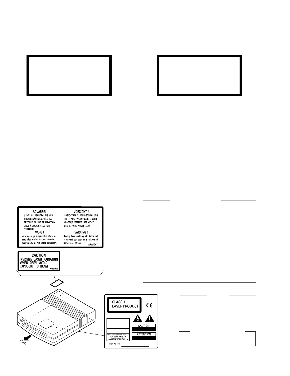
Additional Laser Caution
1. Laser Interlock Mechanism
The loading position detect switch (in CD mechanism
assembly) is set to "CLMP ON(CD CLOSE)" (ON:low
level,OFF:high level) position, the system control
IC(IC5501) get the "CLMP" signal, and hand the laser
"LDON" signal to IC1101.
Then a laser diode can be lighted except when the level of
signal CLMP is low.
The interlock also does not function in the test mode∗.
Laser diode oscillation will continue, if pin 1 of CXA1821M
(IC1101) on the RF UNIT is connected to GND, or pin 19 is
connected to low level (ON), or else the terminals of
Q1101 are shorted to each other (fault condition).
2. When the cover is opened, close viewing of the objective
lens with the naked eye will cause exposure to a Class 1
laser beam.
∗ : Refer to page 42.
THIS PIONEER APPARATUS CONTAINS
LASER OF CLASS 1.
SERVICING OPERATION OF THE APPARATUS
SHOULD BE DONE BY A SPECIALLY
INSTRUCTED PERSON.
LASER DIODE CHARACTERISTICS
MAXIMUM OUTPUT POWER: 5 mW
WAVELENGTH: 780 – 785 nm
2
IMPORTANT
Page 3
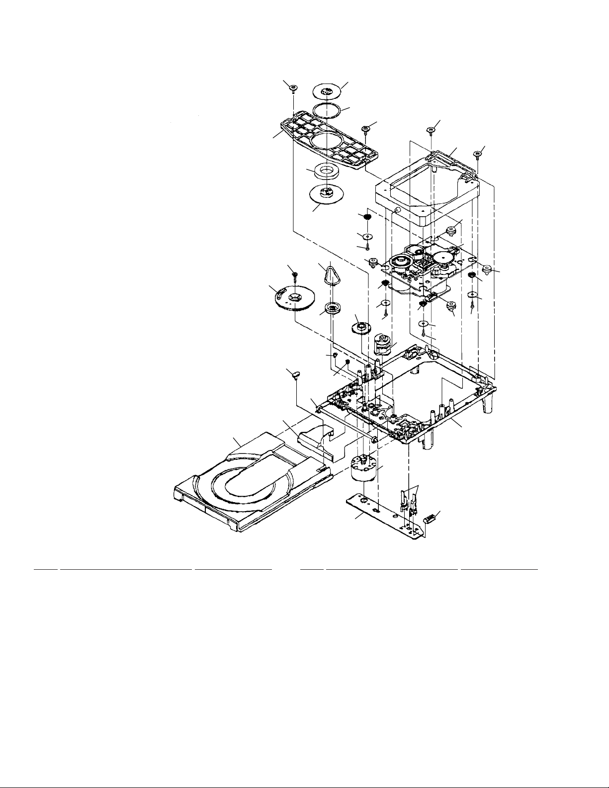
2. EXPLODED VIEWS AND PARTS LIST
NOTES:• Parts marked by "NSP" are generally unavailable because they are not in our Master Spare Parts List.
The mark found on some component parts indicates the importance of the safety factor of the part.
•
Therefore, when replacing, be sure to use parts of identical designation.
Screws adjacent to mark on the product are used for disassembly.
•
XC-L77
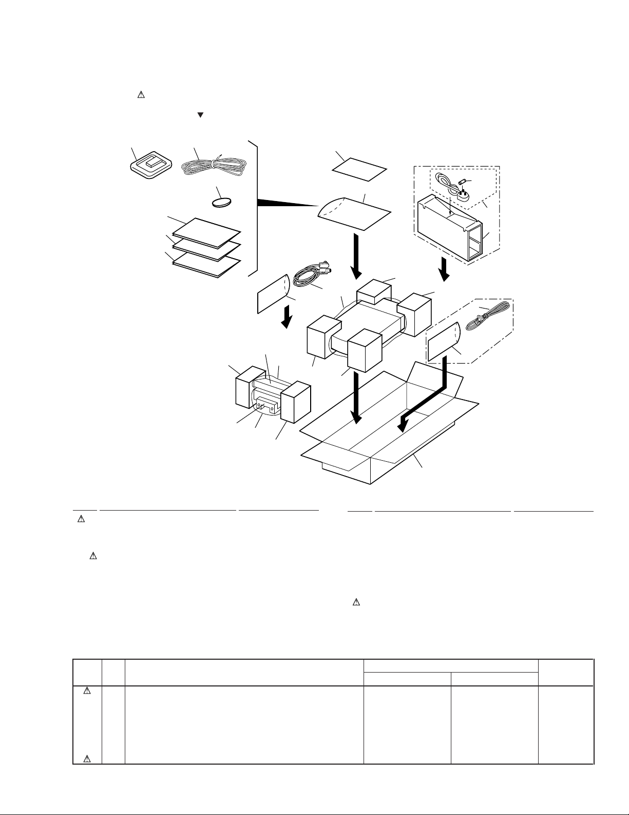
2.1 PACKING
2
MYXK type
only
MYXK type
only
NVXK type
only
3
5
8
7
6
16
REMOTE
CONTROL
11(1/2)
UNIT
DISPLAY
UNIT
16
16
11(1/2)
9(1/2)
17
4
9(2/2)
14
15
NVXK type only
10(1/2)
10(2/2)
16
19
1
18
1
MYXK type
only
(1) PACKING PARTS LIST
Mark No. Description Part No.
NSP 5 Lithium Battery(CR2025) VEM1009
1 AC Power Cord See Contrast table (2)
2 AM Loop Antenna ATB7007
3 FM Wire Antenna ADH7005
4 Display unit connecting cord ADE7014
6 Operating Instructions See Contrast table (2)
7 Operating Instructions See Contrast table (2)
8 Operating Instructions See Contrast table (2)
9 Pad Front AHA7260
10 Pad Rear AHA7261
Mark No. Description Part No.
11 Pad Display AHA7262
12 • • • • •
13 Packing Case See Contrast table (2)
14 Packing Sheet Z23-007
15 Polyethylene Bag Z21-038
NSP 16 Polyethylene Bag CEG1116
NSP 17 Warranty Card ARY7022
18 Sub Packing See Contrast table (2)
19 Fuse (T5A) See Contrast table (2)
(2) CONTRAST TABLE
XC-L77/MYXK and NVXK are constructed the same except for the following :
Mark No. Symbol and Description
1 AC Power Cord ADG7010 ADG7009
6 Operating Instructions (English) Not used ARB7195
7 Operating Instructions (Dutch/Swedish/Spanish/Portuguese) ARC7250 Not used
8 Operating Instructions (English/French/German/Italian) ARE7221 Not used
13 Packing Case AHD7766 AHD7768
18 Sub packing Not used AHD7770
19 Fuse (T5A) Not used AEK7001
MYXK Type NVXK Type
13
Part No.
Remarks
3
Page 4
XC-L77
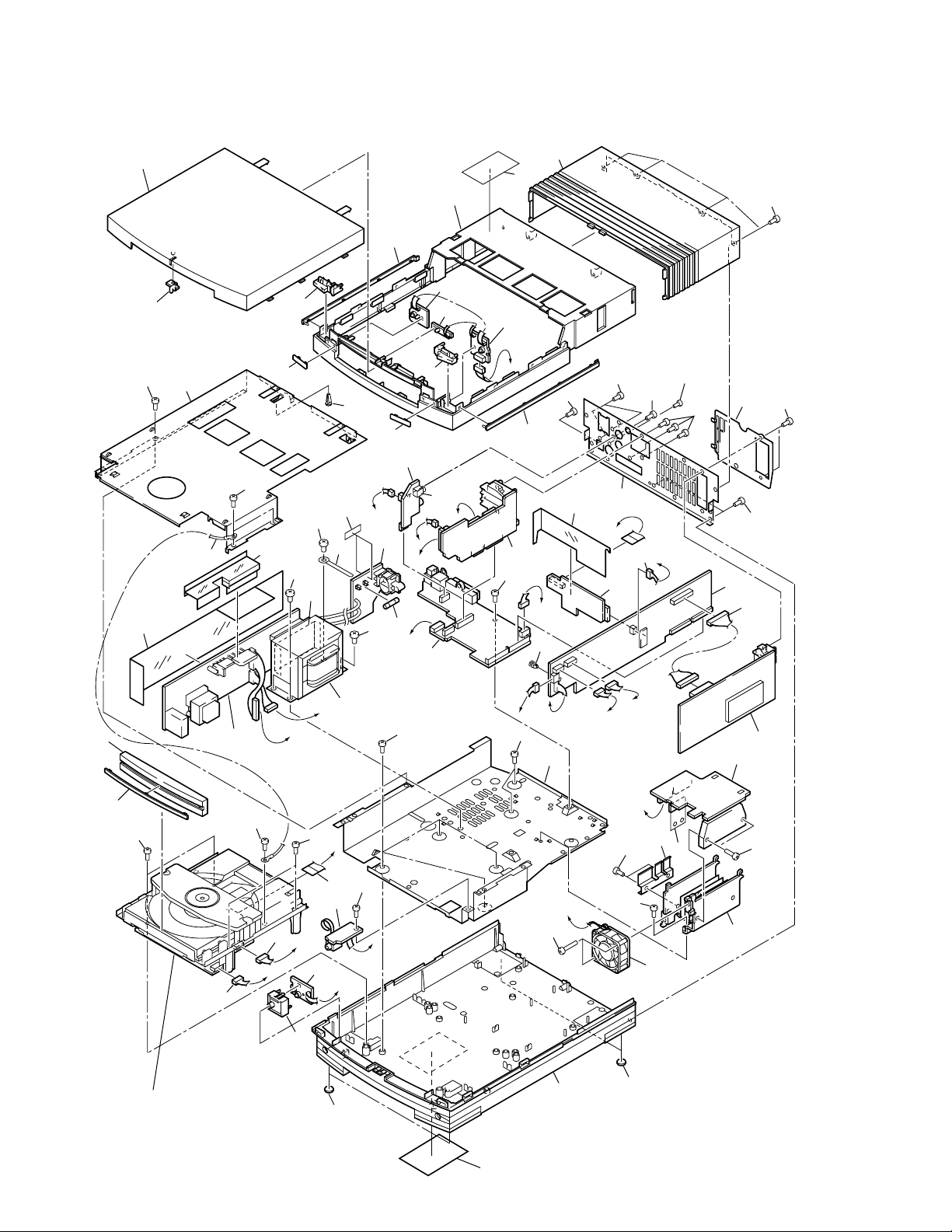
2.2 EXTERIOR
53 (1/2)
58
54
56
53 (2/2)
13
14
59
61
41
12
51
52
41
35
22
22
A
41
56
9
J
44
A
G
29
27
41
45
48
D
87
E
F
22
42
47
41
I
K
21
30
41
46
2
41
41
43
1
20
49
39
×2
57
50
22
62
33
33
34
32
33
16
C
B
41
D
60
4
40
55
57
10
28
I
5
18
29
K
H
B
C
11
38
37
E
F
36
31
15
Refer to "2.3 CD MECHA (1/2)"
"2.4 CD MECHA (2/2)" .
22
6
J
3
G
25
26
H
23
24
22
19
17
25
4
Page 5

XC-L77
(1) EXTERIOR PARTS LIST
Mark No. Description Part No. Mark No. Description Part No.
1 FM/AM TUNER UNIT AXQ7226
2 AMP UNIT AWU7376
3 STBY SW UNIT AWU7386
4 SECONDARY UNIT AWU7378
5 PRIMARY UNIT AWU7379
6 HP UNIT AWU7382
7 MAIN UNIT AWU7374
8 RF UNIT AWU7380
9 SPEAKER UNIT AWU7377
10 AUX UNIT AWU7381
11 CONNECTOR UNIT AWU7375
12 KEYR UNIT AWU7383
13 KEYL UNIT AWU7384
14 BLUE IND. UNIT AWU7385
15 CD MECHA KSL-2130CCM
16 Power transformer (T1) ATS7256
17 DC Fan Motor AXM7014
18 Fuse (FU1 : T1A) AEK1054
NSP 19 Heat Sink ANH7108
20 Screw BBZ30P140FMC
21 Heat Plate ANG7250
22 Screw BBZ30P060FMC
23 Screw BBZ30P300FMC
24 Bottom Base AMA7013
25 Leg AEB7090
26 Name Label See Contrast table (2)
NSP 27 Bottom Plate ANF7016
28 Jack (JA5551) RKN1026
29 Screw BBT30P060FZK
30 Sheet AEE7034
31 Power Button Assy AWL7049
32 TR Barrier AEC7213
33 Screw BBZ40P060FMC
NSP 34 Binder ZCB-4772B
35 Power Barrier AEC7196
36 Connector Assy PG05KK-E20
37 Connector Assy PG06KK-E20
38 16P Flat Flexible Cable/30V ADD7185
NSP 39 Cord with Plug DE010VF0
40 Screw PDZ30P060FMC
41 Screw VPZ30P080FZK
42 Connector Assy PF03PP-Q20
43 Connector assy (J5101) PG14KK-E07
44 Card Spacer AEC7214
45 Rear Panel ANC7826
46 Rear Cover AAX7705
47 Screw PCZ30P080FZK
48 Center Barrier AEC7198
NSP 49 Top Plate ANF7017
50 Push Rivet AEC7221
51 Tray Panel AAN7194
52 Tray Line AAP7059
53 Top Panel Assy AWL7050
54 Button Assy A (6) AWL7044
55 Button Assy B (0) AWL7045
56 Main Line AAP7058
57 Front Line AAP7066
58 CL Lens AAX7704
59 Bonnet AMA7015
60 Sub Barrier AEC7197
NSP 61 Caution Label See Contrast table (2)
NSP 62 Fuse Card AXX7033
(2) CONTRAST TABLE
XC-L77/MYXK and NVXK are constructed the same except for the following :
Mark No. Symbol and Description
26 Name Label ARW7066 ARW7067
NSP 61 Caution Label ARW1047 ARW1050
MYXK Type NVXK Type
Part No.
Remarks
5
Page 6
XC-L77
2.3 CD MECHA (1/2)
5
20
No supplied part
6
8
10
19
28
27
29
4
29
15
14
13
7
26
9
16
12
14
15
12
14
15
6
11
16
6
16
17
16
13
14
15
6
21
3
1
25
22
24
18
23
• CD MECHA (1/2) PARTS LIST
Mark No. Description Part No. Mark No. Description Part No.
1 Tray(C) 2-646-290-01
2 • • • • •
3 Cover(S),Gear 2-625-544-(01)
4 Gear(S),Tray 2-625-535-(01)
5 Plate(S),Chucking 2-625-546-(01)
NSP 6 Screw +PTPWH2.6*7 • • • • •
7 Chucking Yoke(S) 2-625-537-(01)
8 Magnet 1-452-493-(21)
9 Damper(S) 2-625-541-(02)
10 Chucking Pully 2-646-291-(01)
11 Sub Chassis 2130 2-646-288-(01)
12 Coil Spring (Front) 2-627-236-(01)
13 Coil Spring (Back) 2-627-235-(01)
14 Washer 2130 2-646-289-(01)
NSP 15 Screw+P2.6*10 NOSLIT • • • • •
NSP 17 MD Assy • • • • •
NSP 29 Screw +B2.6*2.5 • • • • •
16 Insulator 2-627-234-(01)
18 Outsert Main Chassis 2-625-552-(06)
19 Screw +PTPWH2.6*16 3-319-501-(51)
20 Drive Gear (S) 2-625-547-(01)
21 Control Cam(S) 2-625-545-(04)
22 Leaf Switch 1-692-667-(11)
23 Connector Pin 5p 1-564-721-(11)
24 Loading PC Board 1-640-523-(11)
25 Loading Motor Assy X-2625-117-(1)
26 Midway Gear (S) 2-625-534-(02)
27 Loading Pulley (S) 2-625-536-(02)
28 LM Berut 3-653-387-(00)
6
Page 7
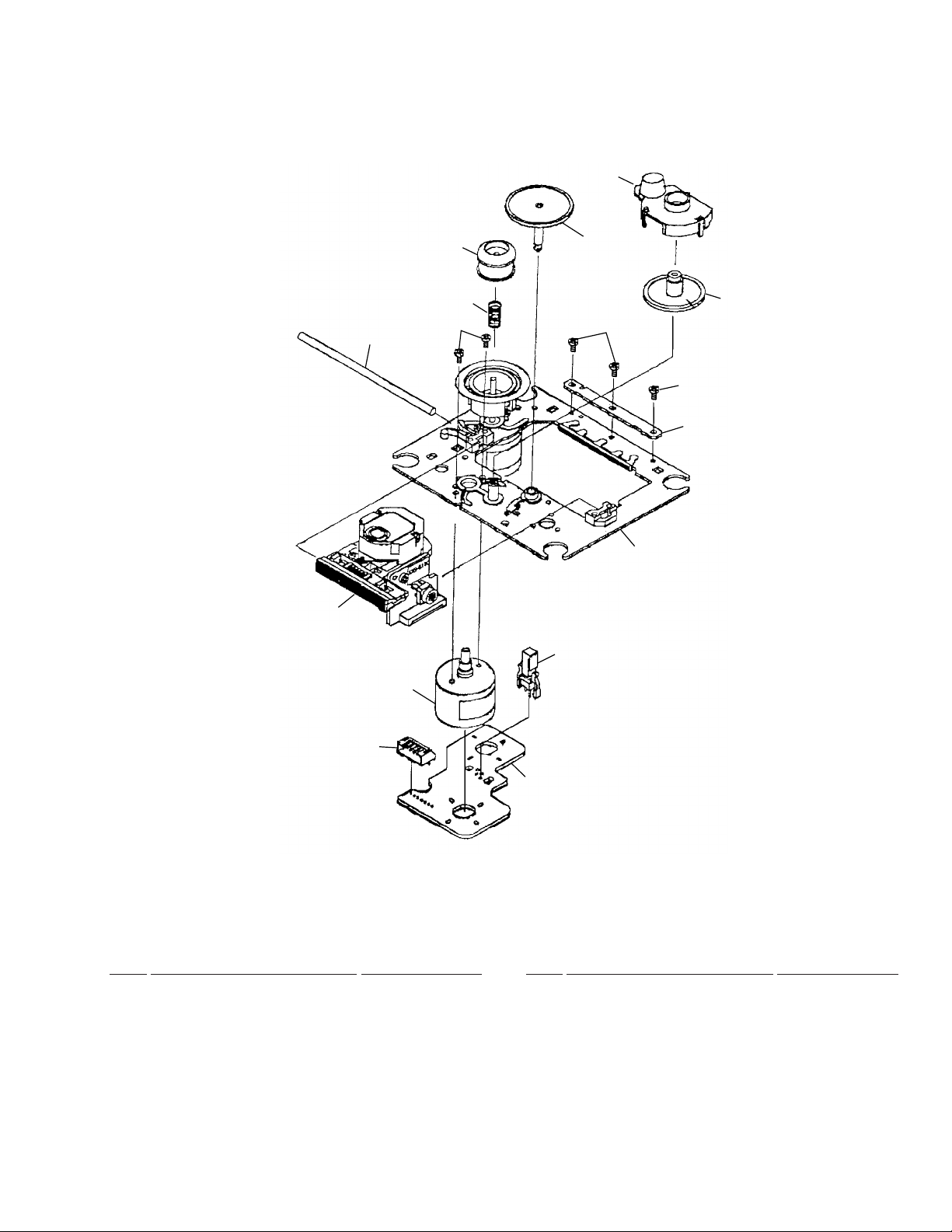
2.4 CD MECHA (2/2)
XC-L77
No supplied part
14
11
10
3
2
5
4
9
12
12
13
1
6
8
7
• CD MECHA (2/2) PARTS LIST
Mark No. Description Part No. Mark No. Description Part No.
1 Motor Chassis Assy X-2625-984-(1)
2 Motor Gear Assy X-2625-769-(1)
3 Sled Shaft 2-626-908-(01)
4 Gear (A)(S) 2-625-188-(02)
NSP 5 Screw +P2*3 • • • • •
6 Leaf Switch 1-572-085-(11)
7 Motor(6p)(S)PCB 1-639-678-(12)
8 Connector Pin 6p 1-564-722-(11)
9 Gear(B)(RP) 2-627-003-(01)
10 Spring(S)Compression 2-625-191-(01)
11 Ring(LO)(S),Center 2-625-477-(01)
12 Screw2*5,Tapping(S) 2-641-386-(01)
13 Reinforcement(S) 2-625-625-(01)
14 KSS-213C(Pick-up) 8-848-483-(05)
7
Page 8
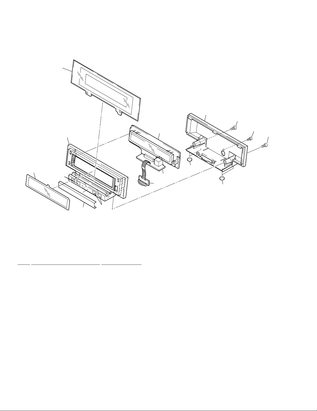
XC-L77
2.5 DISPLAY UNIT
7
8
10
3
6
4
5
4
• DISPLAY UNIT PARTS LIST
Mark No. Description Part No.
NSP 2 FLSUB UNIT AWU7388
NSP 4 Magnet PMF1010
1 FL UNIT AWU7387
3 Display Panel AMB7630
5 Display Plate AAH7056
12
1
9
2
9
11
10
6 FL Filter AEC7195
7 Window AAK7668
8 Display Cover AMC7033
9 Leg AEB7090
10 Screw VPZ30P080FZK
11 Screw PCZ30P080FZK
12 DETACH UNIT AWU7389
8
Page 9
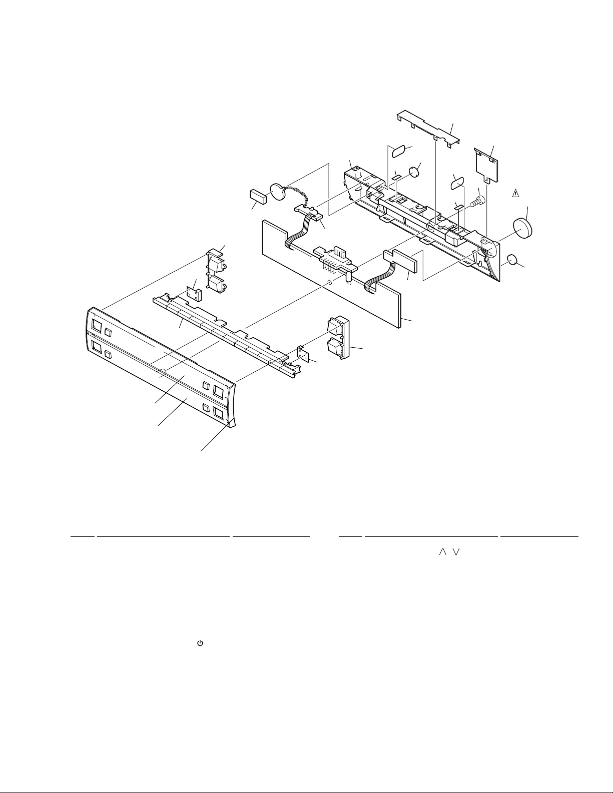
2.6 REMOTE CONTROL UNIT
5
9
8
10
11
6
7
9
1
3
2
15
14
16
16
17
17
12
18
19
Litium Battery
15
13
XC-L77
,
) AAD7542
• REMOTE CONTROL UNIT PARTS LIST
Mark No. Description Part No. Mark No. Description Part No.
1 CONTROL UNIT AWU7390
2 SWITCH UNIT AWU7411
3 TERMINAL UNIT AWU7412
4 • • • • •
5 Control Panel AMB7631
6 Control Plate 1 AAH7051
7 Control Plate 2 AAH7052
8 Control Button AAD7530
9 Light Barrier AEC7201
10 VOL. Button (MENU, ) AAD7540
11 VOL. Button (
12 Control Cover AMC7034
13 Spacer AEB7163
14 Screw VPZ30P080FZK
15 Leg AEB7090
16 Rear Sheet 1 AED7037
17 Rear Sheet 2 AED7032
18 Magnet Plate ANG7255
19 Battery Cover AMC7035
9
Page 10
1
23
XC-L77
3. BLOCK DIAGRAM AND SCHEMATIC DIAGRAM
3.1 BLOCK DIAGRAM
4
A
F
BLUE IND. UNIT
(AWU7385)
E
KEYL UNIT
(AWU7384)
B
A
FM/AM
TUNER
UNIT
(AXQ7226)
KEYR UNIT
D
(AWU7383)
STBY SW UNIT
G
(AWU7386)
C
C 1/2, C 2/2
MAIN UNIT (AWU7374)
IC5521
(ICP-N20)
(0.8A)
IC3001
(M62420FP)
7 2
E-VOL.
IC3071
(BA4560F)
OTHER
CH
IC3101
(BU4052BCF)
BUFFER
1
IC3111
(NJM4558MD)
13
AMP.
IC3201
(NJM4558MD)
6
LPF
11
13
3
12
1
15
14
FUNCTION
SW
AUX UNIT (AWU7381)
N
1
IC3501
(NJM4558MD)
HP UNIT
M
(AWU7382)
3
PHONES
IC1201
C
DRIVER
IC1301
(M56758FP)
(CXD2587Q)
SERVO
CONTROL
43
72
Q1401
MUTE
CD MECHA
(KSL-2130CCM)
16
RF AMP.
D
B
IC1101
(CXA1821M)
RF UNIT
(AWU7380)
Q61
D61
+B
UN+12
-B
UN+5
IC6
IC5
D21
10
1234
SECONDARY UNIT
J
(AWU7378)
D31
UN-6
IC81
D11
IC4
IC2
IC1
IC3
T2
D81
RY81
T1 : POWER
TRANSFORMER
: ATS7256
T2 : ATT7056
Page 11
5
678
XC-L77
Note : When ordering service parts, be sure to refer to "EXPLODED VIEWS and P AR TS LIST" or "PCB PAR TS LIST".
: AUDIO SIGNAL ROUTE
DISPLAY UNIT
FL UNIT
T
JA6801
AKP7128
CN5703
AKP7128
O
P
(AWU7387)
FLSUB UNIT
(AWU7388)
DETACH UNIT
(AWU7389)
A
B
CONNECTOR UNIT
L
(AWU7375)
Q5522
IC5222
Q5521
IC5221
REMOTE
CONTROL
UNIT
L/R AMP.
14
Q3311
MUTE
Q
CONTROL UNIT
(AWU7390)
IC3301(STK407-040B)
Q3411
MUTE
7
WOOFER AMP.
3 14
IC3303
(TDA7294V)
HPF
AMP UNIT
H
(AWU7376)
IC32
IC33
IC23
S
SWITCH
UNIT
(AWU7411)
R
TERMINAL
UNIT
(AWU7412)
C
IC24
WOOFER
Q3431
Q3432
LEVEL
RY3601
RY3602
SPEAKER UNIT
I
(AWU7377)
PRIMARY
K
UNIT
(AWU7379)
5
6
CN3331
AKE1026
D
DC FAN MOTOR
: AXM7014
AC POWER CORD AC250V
MYXK : ADG7010
NVXK : ADG7009
11
7
8
Page 12
1
XC-L77
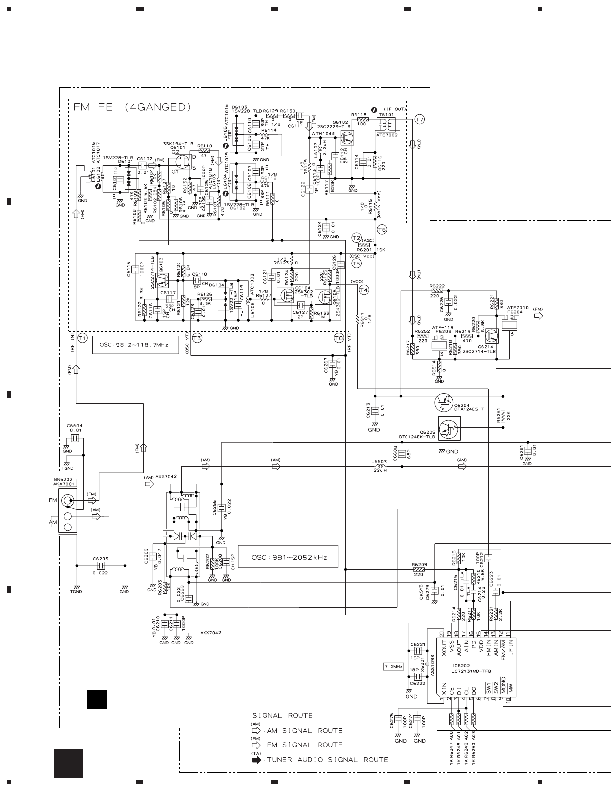
3.2 FM/AM TUNER UNIT
23
4
A
RF AMP
OSC
B
MIX AMP
BUFFER
IF AMP
FM +B SW
C
AM RF TUNING BLOCK
D
PLL
FM/AM TUNER MODULE
A
(AXQ7226)
12
A
1234
Page 13
5
678
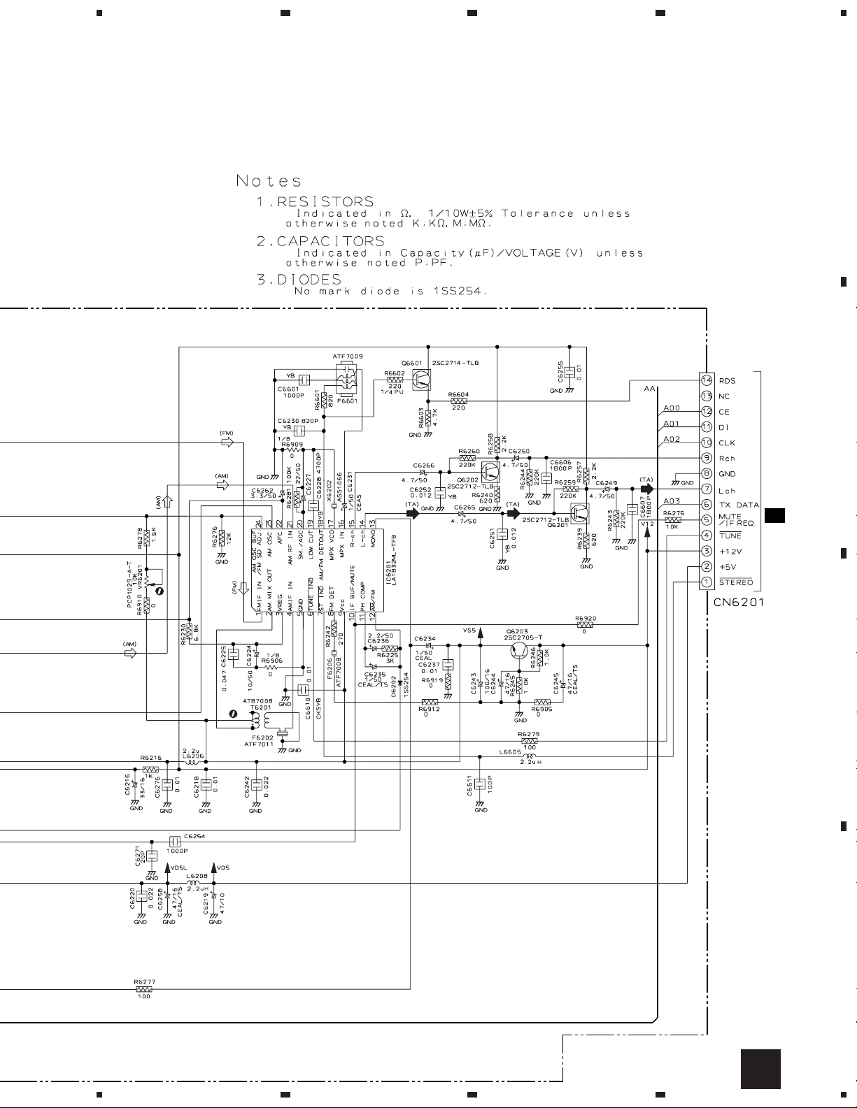
XC-L77
A
B
AF AMP
REGULATOR
CN5101
2/2
C
AF AMP
B14B-PH-K-S
C
D
A
5
6
7
8
13
Page 14
1
23
XC-L77
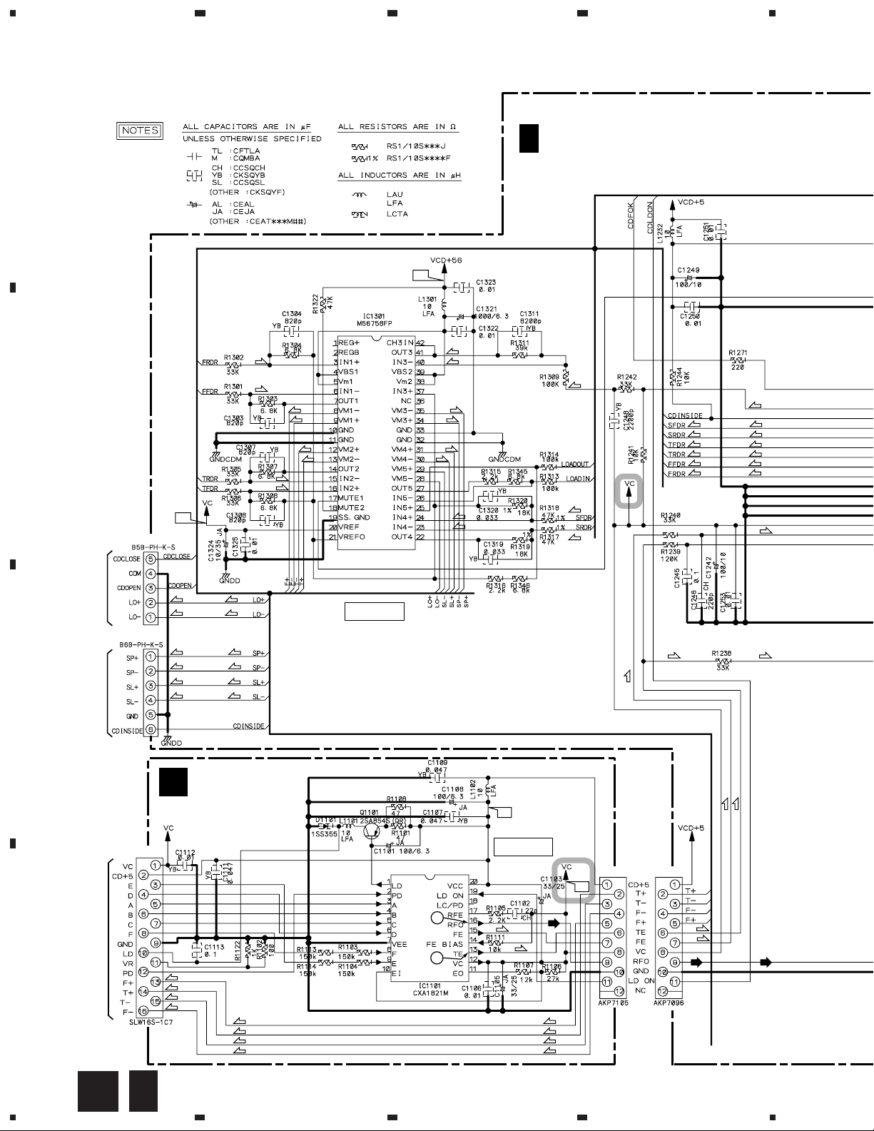
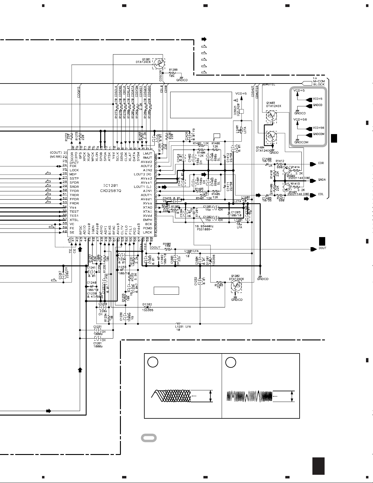
3.3 RF and MAIN (1/2) UNITS
4
A
C 1/2
MAIN UNIT
(AWU7374)
5.6
(S)
(C)
(C)
(S)
(S)
(S)
(S)
(C)
(C)
(C)
(C)
(C)
(C)
(T)
(T)
(F)
(F)
(S)
(C)
(C)
(T)
(T)
(F)
(F)
(F)
(F)
(F)
(F)
B
2.4
(F)
(T)
(T)
(T)
(T)
CN1302
(L) (L)
(L)
To CD MECHA
CN1301
(S)
(S)
(C)
(C)
(L)
(S)
(S)
(C)
(C)
DRIVER
(T) (T)
(F)
C
To CD MECHA
RF UNIT
B
(AWU7380)
CN1101
1
2
D
To CD MECHA (PICKUP)
(F)
(T)
(T)
(F)
(F)
(T)
(T)
(F)
4.8
RF AMP.
(F)
(T)
CN1102 CN1202
2.4
(F)
(T)
(T)
(F)
(T)
(F)
(T)
(F)
14
1/2
B
C
1234
Page 15
5
678
XC-L77
: CD AUDIO SIGNAL ROUTE
(F)
: FOCUS SERVO LOOP LINE
(T)
: TRACKING SERVO LOOP LINE
(S)
: SPINDLE SERVO LOOP LINE
(C)
: CARRIAGE SERVO LOOP LINE
(L)
: LOADING SERVO LOOP LINE
CAUTION :
FOR CONTINUED PROTECTION
AGAINST RISK OF FIRE.
REPLACE ONLY WITH SAME TYPE
NO. ICP-N20 FOR IC5521 MFD,
BY ROHM CO. , LTD.
CD
A
4.8
(S)
(C)
(C)
(T)
(T)
(F)
(F)
(F)
(T)
(T)
C 2/2
B
C 2/2
SERVO
C
Note: The encircled numbers denote measuring point in the schematic diagram.
IC1101- Pin 16:
1
PLAY MODE (RF)
H : 500nsec/div
1.2Vp-p
VC
IC1101- Pin 13 :
2
TEST MODE,
Tracking Open (TRER)
H : 5msec/div
3.5Vp-p
VC
D
VC : IC1101- Pin12
: The power supply is shown with the marked box.
1/2
C
5
6
7
8
15
Page 16
1
23
XC-L77
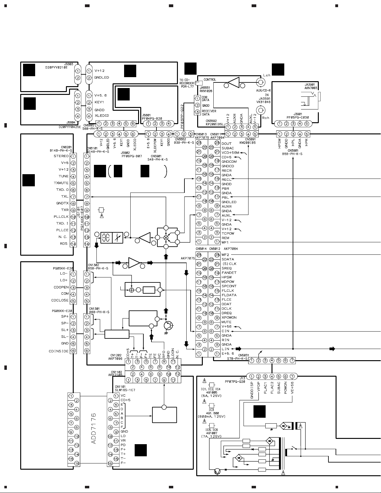
3.4 MAIN (2/2), KEYR, KEYL, BLUE IND. and STBY SW UNITS
C 2/2
MAIN UNIT (AWU74374)
: The power supply is shown with the marked box.
C 1/2
A
CD
4
CN5013
CN5011
(REC)
(PB)
C 1/2
L
(A)
B
(A)(A)
CN5014
(REC)
(PB)
5
N
CN5552
CN5551
CN5012
L
(TX)
(PB)
(REC)
C
(TX)(TX)
(REC)
(PB)
BUFFER
(A)
(PB)
(TX)
FUNC 1
D
(REC)
12
9.5
E-VOL
4.9
C 1/2
-12
16
2/2
C
1234
Page 17
5
678
XC-L77
: AUDIO SIGNAL ROUTE
(TX)
: TUNER AUDIO SIGNAL ROUTE
(A)
: AUX AUDIO SIGNAL ROUTE
(REC)
: REC AUDIO SIGNAL ROUTE
(PB)
: PB AUDIO SIGNAL ROUTE
CN5901
J5902
STBY SW UNIT
G
(AWU7386)
J5801
POWER
CN5802
5
KEYR UNIT
D
(AWU7383)
J5803
J5804
CN5101
(TX)
BLUE IND. UNIT
F
(AWU7385)
KEYL UNIT
E
(AWU7384)
A
CN6201
A
B
AC PULSE
5.6
H.P. AMP.
(TX)
5.6
(TX)(TX)
C
C 1/2
-12
12
D
2/2
C
5
6
7
FED
G
8
17
Page 18

1
23
XC-L77
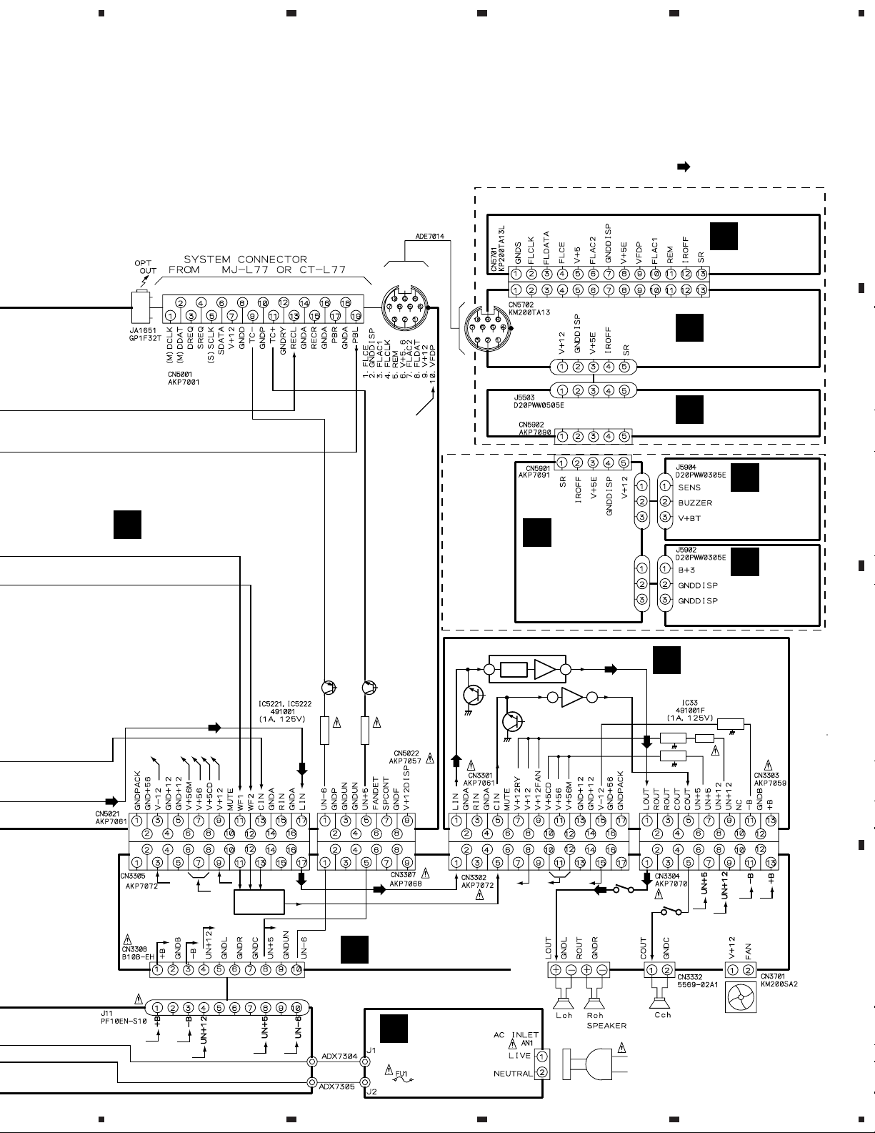
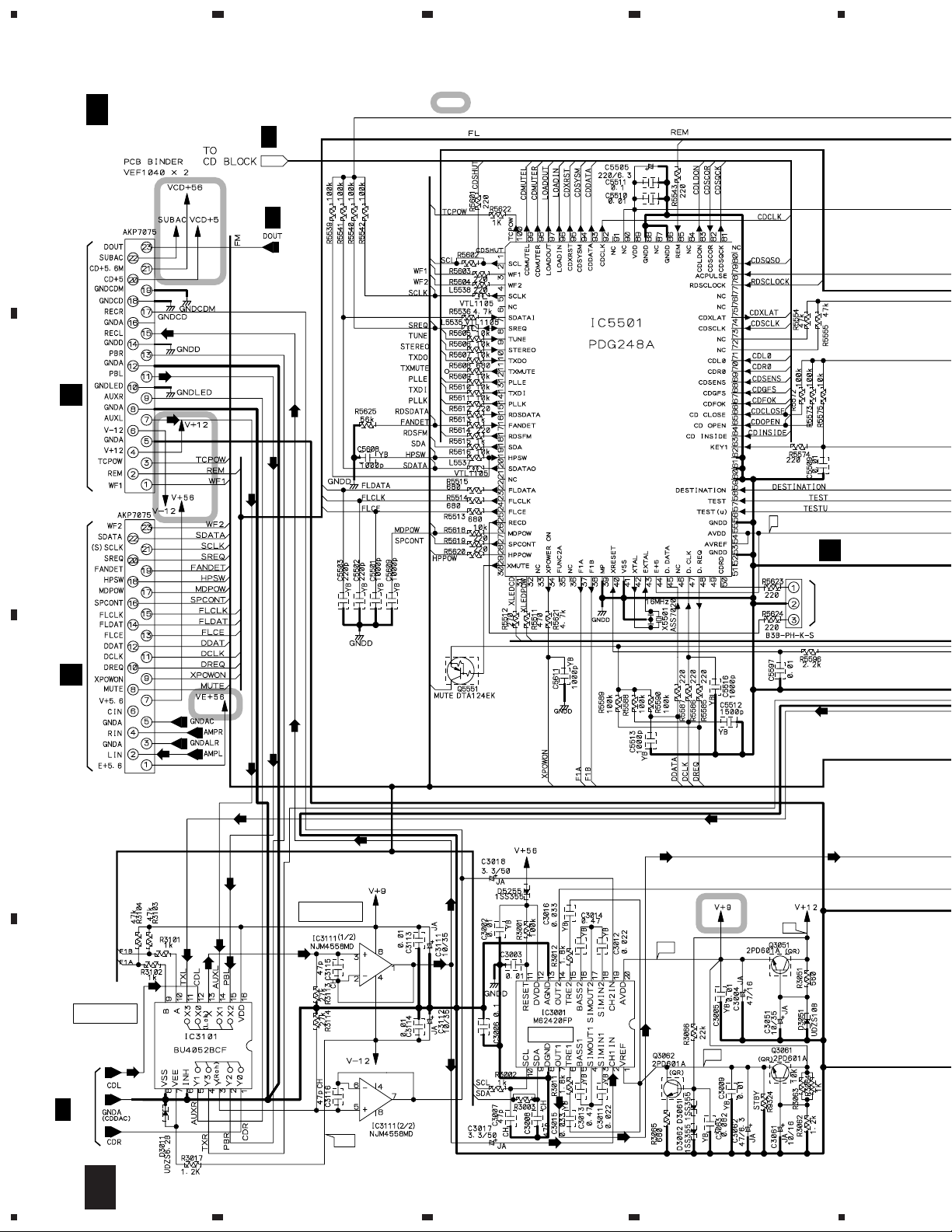
3.5 AMP, SPEAKER, SECONDARY and PRIMARY UNITS
4
WOOFER AMP.
A
B
12
12
L/R AMP.
5.6
AMP UNIT (AWU7376)
H
CN3303 CN3304
27
30-30
C
PRIMARY UNIT
K
(AWU7379)
AN1
AC IN
• NOTE FOR FUSE REPLACEMENT
CAUTION -
FOR CONTINUED PROTECTION AGAINST
RISK OF FIRE. REPLACE WITH SAME
TYPE AND RATINGS ONLY.
CAUTION : FOR CONTINUED PROTECTION
D
AGAINST RISK OF FIRE.
REPLACE ONLY WITH SAME TYPE
NO. 491005 FOR IC1, IC2 AND IC4,
491.008 FOR IC3, 491007 FOR IC5
AND IC6 MFD, BY LITTELFUSE INC.
CAUTION :
FOR CONTINUED PROTECTION
AGAINST RISK OF FIRE.
REPLACE ONLY WITH SAME TYPE
NO. 491001F FOR IC33 MFD, BY
LITTELFUSE INC.
MAIN TRANS.
J1
J2
J4
J3
SUB TRANS.
-12
-44
-35
CN3308J11
J13
CN5031
SECONDARY
UNIT
J
(AWU7378)
L
18
H I J K
1234
Page 19

5
678
XC-L77
: AUDIO SIGNAL ROUTE
A
CN3301 CN3302
SPEAKER UNIT
I
(AWU7377)
CN3305
CN5021
L
WOOFER LEVEL CONT
CN3307
14
CN5022
B
L
-14
LEVEL DET.
FAN CONT
PROTECTION
CN3701
CN3331
AKE7001
CN3332
To
DC FAN
MOTOR
C
To SPEAKER
D
: The power supply is shown with the marked box.
5
6
H I
7
8
19
Page 20

1
23
XC-L77
3.6 CONNECTOR, HP and AUX UNITS
4
A
B
CN5013
C 2/2
CN5011
CN3901
J3901
JA3901
PHONES
CN3091
CN3592
(A)(A)
M
HP UNIT
(AWU7382)
(R)(R)
(PB)(PB)
(A)(A)
(PB)
(A)
(R)
(PB)
C
(R)
CN5012
CN5014
C 2/2
D
20
L M N
1234
CN5021
CN3305
I
CN5022
CN3307
I
J13
J
CN5031
Page 21

5
678
XC-L77
(R)
: AUDIO SIGNAL ROUTE (HP)
(A)
1/2
(A)
(A)(A)
L
: AUX AUDIO SIGNAL ROUTE
CONNECTOR UNIT (AWU7375)
: REC AUDIO SIGNAL ROUTE
(PB)
: PB AUDIO SIGNAL ROUTE
A
(A)
CN5551
C 2/2
CN5552
(PB)
(R)
2/2
TCPOWSW
1A/125V
AUX UNIT (AWU7381)
N
With CT-L77 : 14V
Without CT-L77 : 0V
(A)
(PB)
JA1651
JA6801
AKP7128
B
(PB)
1A/125V
MDPOWSW
CAUTION :
FOR CONTINUED PROTECTION
AGAINST RISK OF FIRE.
REPLACE ONLY WITH SAME TYPE
NO. 491001 FOR IC5221 AND
IC5222 MFD, BY LITTELFUSE INC.
: The power supply is shown with the marked box.
With CT-L77 : -14V
Without CT-L77 : 0V
With MJ-L77 : 12V
Without MJ-L77 : 0V
(R)
(R)
(R)
C
From MJ-L77 or CT-L77
CN5001
D
L N
5
6
7
8
21
Page 22

1
23
XC-L77
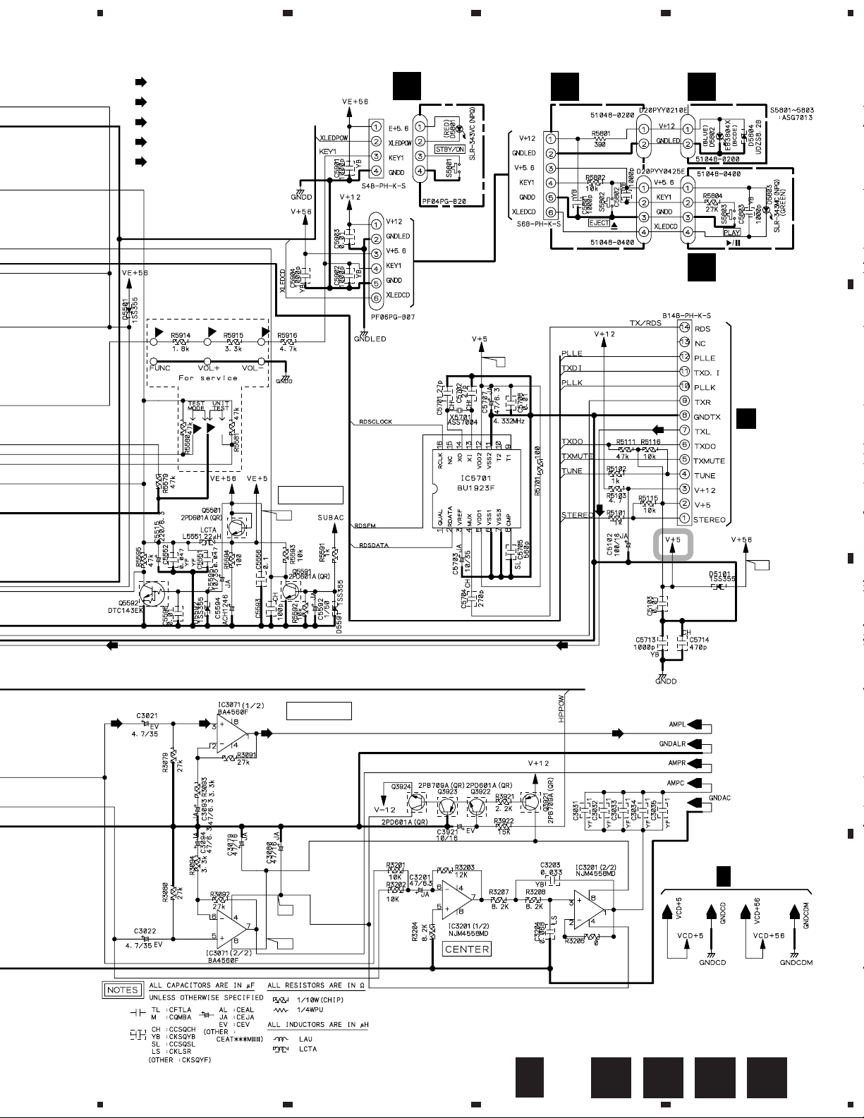
3.7 FLSUB, DETACH, CONTROL, TERMINAL, SWITCH and FL UNITS
FLSUB UNIT
O
A
B
(AWU7388)
CN5703
AKP7128
T
CN5702 CN5701
FL UNIT (AWU7387)
4
5.1
FL DRIVER
J5503
C
FL DRIVER RESET
CN5902
P
DETACH UNIT
(AWU7389)
D
22
O
P T
1234
Page 23

5
CONTROL UNIT
S5901 : 4 (1 –)
S5902 : (VOL)
S5903 : (TUNER)
S5904 : ¢ (+ ¡)
S5905 : (VOL)
S5906 : (CD)
S5907 : 7 (CANCEL)
S5908 : TIMER/ (CHARACTER)
S5909 : TAPE (REC)
678
S5910 : MD (REC)
S5911 : SET
S5912 : DISPLAY
S5913 : (TAPE)
S5914 : AUX / CD-R
S5915 : STANDBY/ON
S5916 : MENU
S5917 : SOUND
S5918 : (MD)
XC-L77
A
B
CONTROL UNIT
Q
(AWU7390)
REMOTE
LOCATOR
CN5901
J5904
(O)
(I) (I)
(O)
R
TERMINAL
UNIT
(AWU7412)
J5902
Lithium
Battery
C
(O)
(O)
(I)
1/2
(I)
(O)
(I)
S
SWITCH UNIT
(AWU7411)
(I)
: SOUND INPUT SIGNAL
(O)
: SOUND OUTPUT SIGNAL
5
2/2
D
Q R S T
6
7
8
23
Page 24

XC-L77
4. PCB CONNECTION DIAGRAM
NOTE FOR PCB DIAGRAMS :
1. Part numbers in PCB diagrams match those in the schematic
diagrams.
2. A comparison between the main parts of PCB and schematic
diagrams is shown below.
Symbol In PCB
Diagrams
BCE
BCE
D
Symbol In Schematic
Diagrams
BCEBCE
BCE
DGGSS
BCE
DGS
Part Name
Transistor
Transistor
with resistor
Field effect
transistor
Resistor array
3. The parts mounted on this PCB include all necessary parts for
several destinations.
For further information for respective destinations, be sure to
check with the schematic diagram.
4. View point of PCB diagrams.
Connector
Capacitor
SIDE A
P.C.Board
Chip Part
SIDE B
3-terminal
regulator
24
Page 25

1
CN5101
C
FM/AM TUNER MODULE
A
FM/AM TUNER MODULE
A
(ANP7160-B)
VR6201
Q6204 Q6203
IC6202Q6205Q6102 - Q6105Q6101
Q6501 Q6202Q6601Q6214 Q6201 IC6201
SIDE A
SIDE B
4.1 FM/AM TUNER UNIT
234
XC-L77
A
B
C
D
1
2
3
A
4
25
Page 26

1
23
XC-L77
4.2 RF, MAIN, KEYR, KEYL, BLUE IND. and STBY SW UNITS
STBY UNIT
G
A
To
CD
MECHA
D
KEYR UNIT
IC1301 IC1201 Q1201Q1202 Q5591 Q1401-Q1404
Q5501 Q5592IC5501
IC5521
4
N
B
(ANP7323-B)
BLUE IND. UNIT
F
KEYL UNIT
E
KEYL UNIT
E
BLUE IND. UNIT
F
C
(ANP7323-B)
KEYR UNIT
D
MAIN UNIT
C
MAIN UNIT
C
D
Q5551
STBY UNIT
G
26
C D E F G
1234
Page 27

5
678
XC-L77
N
CN5551
IC1311 Q3051 Q3062 IC3071
Q3921-Q3924 IC3201
L
CN5011
IC5701
L
(ANP7322-C)
CN5012
A
CN6201
To
CD
MECHA
RF UNIT
B
A
B
Q1101
SIDE A
(ANP7322-C)
(ANP7322-C)
C
(ANP7322-C)
IC1101
D
RF UNIT
IC3001IC3101 Q3061Q5551
B
SIDE B
B C
5
6
7
8
27
Page 28

1
XC-L77
4.3 AMP and SPEAKER UNITS
A
AMP UNIT
H
23
IC3301
4
Q3312
Q3313
Q51
IC23
Q31
IC24
IC32
Q3311
Q3421
Q3411
B
(ANP7322-C)
IC3303
AMP UNIT
28
H
(ANP7322-C)
H
1234
C
D
Page 29

5
678
XC-L77
A
J
J11
To
DC FAN
MOTOR
SPEAKER UNIT
I
CN5022
L
SIDE A
CN5021
L
(ANP7322-C)
Q3604-Q3606
Q3432
Q3431
Q3703-Q3705
SPEAKER
B
SPEAKER UNIT
I
(ANP7322-C)
Q3702
Q3701
Q3705
Q3601-Q3603
Q3607
C
D
SIDE B
5
6
7
8
I
29
Page 30

1
C
23
XC-L77
4.4 SECONDARY and PRIMARY UNITS
A
PRIMARY UNIT
K
AC IN
B
SECONDARY UNIT
J
4
L
(ANP7322-C)
SIDE A
SECONDARY UNIT
PRIMARY UNIT
K
C
J
(ANP7322-C)
D
SIDE B
30
J K
1234
Page 31

CN5031
L
5
678
XC-L77
A
CN3308
I
B
IC81
(ANP7322-C)
Q61IC3IC1IC2IC6IC5IC4 Q82
C
(ANP7322-C)
D
J
5
6
7
8
31
Page 32

1
23
XC-L77
4.5 CONNECTOR, HP and AUX UNITS
A
HP UNIT
M
B
CN5014
C
CN5013
C
4
I
CN3307
Q5521
C
From
MJ-L77
or
CT-L77
CN3305
J13
J
I
IC5221
Q5232
Q5231
Q5522
IC5222
Q6802
O
CN5703
D
(ANP7322-C)
SIDE A
CN5552
CONNECTOR
L
C
UNIT
AUX UNIT
N
32
L M N
1234
Page 33

1
234
XC-L77
Q3911
Q3901
Q3902
Q5531
HP UNIT
M
A
B
IC3501
Q5523
Q5526
(ANP7322-C)
SIDE B
C
D
CONNECTOR
L
UNIT
AUX UNIT
N
L M N
1
2
3
4
33
Page 34

1
23
4
XC-L77
4.6 FLSUB, DETACH, CONTROL, TERMINAL, SWITCH and FL UNITS
A
B
FL UNIT
T
Q5751
FLSUB UNIT
O
JA6801
L
DETACH
P
UNIT
C
SWITCH UNIT
S
D
CONTROL UNIT
Q
(ANP7323-B)
TERMINAL
R
UNIT
Lithium Battery
34
O P Q R S T
1234
SIDE A
Page 35

1
234
XC-L77
Q5702-Q5705 IC5701 Q5701
FL UNIT
T
O
Q5707
A
B
FLSUB UNIT
TERMINAL
R
UNIT
CONTROL UNIT
Q
Q5901
IC5901
(ANP7323-B)
Q5902 Q5952 Q5951
SIDE B
DETACH
P
UNIT
Q5953Q5903
SWITCH UNIT
S
IC5902
C
D
O P Q R S T
1
2
3
4
35
Page 36

XC-L77
Mark No. Description Part No. Mark No. Description Part No.
5. PCB PARTS LIST
NOTES:•The mark found on some component parts indicates the importance of the safety factor of the part.
Therefore, when replacing, be sure to use parts of identical designation.
When ordering resistors, first convert resistance values into code form as shown in the following examples.
•
Ex.1 When there are 2 effective digits (any digit apart from 0), such as 560 ohm and 47k ohm (tolerance is shown by J=5%,
and K=10%).
560 Ω→56 × 10
47k Ω→47 × 10
0.5 Ω→R50 ..................................................................................... RN2H
1
→ 561 ........................................................ RD1/4PU 5 6 1 J
3
→ 473 ........................................................ RD1/4PU 4 7 3 J
R 5 0
K
1 Ω→1R0 ..................................................................................... RS1P 1 R 0 K
Ex.2 When there are 3 effective digits (such as in high precision metal film resistors).
5.62k Ω→ 562 × 10
1
→ 5621 ...................................................... RN1/4PC 5 6 2 1 F
Mark No. Description Part No.
LIST OF PCB ASSEMBLIES
NSP MAINCOMP ASSY AWM7447
NSP FLSUB UNIT AWU7388
SEMICONDUCTORS
COILS AND FILTERS
FM/AM TUNER UNIT AXQ7226
MAIN UNIT AWU7374
CONNECTOR UNIT AWU7375
AMP UNIT AWU7376
SPEAKER UNIT AWU7377
SECONDARY UNIT AWU7378
PRIMARY UNIT AWU7379
RF UNIT AWU7380
AUX UNIT AWU7381
HP UNIT AWU7382
DISPCOMP ASSY AWX7434
KEYR UNIT AWU7383
KEYL UNIT AWU7384
BLUE IND. UNIT AWU7385
STBY SW UNIT AWU7386
FL UNIT AWU7287
DETACH UNIT AWU7389
CONTROL UNIT AWU7390
SWITCH UNIT AWU7411
TERMINAL UNIT AWU7412
FM/AM TUNER UNIT
A
IC6201 LA1832ML
IC6202 LC72131MD
Q6102 2SC2223
Q6203 2SC2705
Q6201, Q6202 2SC2712
Q6103, Q6214, Q6601 2SC2714
Q6104, Q6105 2SK302
Q6101 3SK194
Q6204 DTA124ES
Q6205 DTC124EK
D6202 1SS254
D6101–D6104 1SV228
L6106 FM COIL ATC1003
L6105 FM RF COIL ATC1015
L6101 FM ANTENNA COIL ATC1016
L6102 FM ANTENNA COIL ATC1017
L6103 FM RF DRIVE COIL ATC1018
Mark No. Description Part No.
L6104 FM RF
F6203 FM CERAMIC FILTER ATF-119
F6206 CERAMIC DISCLIMINATORATF7008
F6601 ANTIBIRDY FILTER ATF7009
F6204 CERAMIC FILTER ATF7010
F6202 AM CERAMIC FILTER ATF7011
L6107 TIP COIL ATH1043
L6603 LAU220J
L6206, L6208, L6605 LAU2R2J
TUNING
COIL ATC1019
TRANSFORMERS
T6201 AM IF TRANSFORMER ATB7008
T6101 FM IF TRANSFORMER ATE7002
CAPACITORS
C6113, C6212, C6274, C6275, C6611 CCSQCH101J50
C6116, C6208, C6221 CCSQCH150J50
C6222 CCSQCH180J50
C6271 CCSQCH200J50
C6117 CCSQCH330J50
C6608 CCSQCH680J50
C6118 CCSQCH8R0D50
C6111, C6122 CCSQCK1R0C50
C6112, C6127 CCSQCK2R0C50
C6105 CCSQSL471J50
C6101 CCSQTH110J50
C6119 CCSQTH150J50
C6109 CCSQTH270J50
C6107, C6110 CCSQTH300J50
C6106 CCSQTH330J50
C6234, C6235 CEAL1R0M50
C6245 CEAL470M16
C6224 CEAT100M50
C6243 CEAT101M16
C6231 CEAT1R0M50
C6227 CEAT220M25
C6236 CEAT2R2M50
C6216 CEAT330M16
C6262 CEAT3R3M50
C6219 CEAT470M10
C6244 CEAT470M16
C6249, C6250, C6265, C6266 CEAT4R7M50
C6258 CEJA470M16
C6215 CFTLA103J50
C6214 CFTLA224J50
C6115, C6125, C6126, C6211, C6254 CKSQYB102K50
C6601 CKSQYB102K50
C6102, C6114, C6121, C6123, C6124 CKSQYB103K50
C6210, C6213, C6237, C6267, C6276 CKSQYB103K50
C6279, C6281, C6604 CKSQYB103K50
36
Page 37

XC-L77
Mark No. Description Part No. Mark No. Description Part No.
C6251, C6252 CKSQYB123K50
C6606, C6607 CKSQYB182K50
C6203, C6259 CKSQYB223K50
C6228 CKSQYB472K50
C6209 CKSQYB473K50
Q3051, Q3061, Q3062, Q3922, Q3924 2PD601A
Q5501, Q5591 2PD601A
Q1401, Q1402 2SD2114K
Q1201, Q1202, Q1403, Q1404, Q5551 DTA124EK
Q5592 DTC143EK
C6230 CKSQYB821K50
C6218, C6223, C6255 CKSQYF103Z50
C6220, C6226, C6242, C6256 CKSQYF223Z50
C6225 CKSQYF473Z50
C6610 CKSYB103K50
RESISTORS
R6602 RD1/4PU221J
R6115, R6119, R6123, R6127, R6129 RS1/8S0R0J
R6906, R6909, R6911 RS1/8S0R0J
R6112 RS1/8S473J
VR6201 (10kΩ) PCP1029
Other Resistors RS1/10S J
OTHERS
BN6202 ANTENNA TERMINAL AKA7001
X6202 CERAMIC (456kHz) ASS1066
X6201 CRYSTAL (7.2000MHz) ASS1093
AM RF TUNING BLOCK
RF UNIT
B
AXX7042
SEMICONDUCTORS
IC1101 CXA1821M
Q1101 2SA854S
D1101 1SS355
COILS AND FILTERS
L1101, L1102 LFA100J
CAPACITORS
C1102 CCSQCH220J50
C1101, C1108 CEJA101M6R3
C1103, C1105 CEJA330M25
C1112 CKSQYB103K50
C1107, C1109, C1111 CKSQYB473K50
C1106 CKSQYF103Z50
C1113 CKSQYF104Z25
RESISTORS
All Resistors RS1/10S J
OTHERS
CN1102 12P SOCKET AKP7105
CN1101 FFC CONNECTOR SLW16S-1C7
MAIN UNIT
C
SEMICONDUCTORS
IC3071 BA4560F
IC5701 BU1923F
IC3101 BU4052BCF
IC5521 (0.8A) ICP-N20
IC1201 CXD2587Q
IC1301 M56758FP
IC3001 M62420FP
IC3111, IC3201 NJM4558MD
IC5501 PDG248A
Q3921, Q3923 2PB709A
D1202, D3061, D3062, D5101, D5255 1SS355
D5501, D5591, D5592 1SS355
D1201 1SS356
D3051 UDZS10B
D3011 UDZS6.2B
COILS AND FILTERS
L1401, L1402 LCTA100J3225
L5551 LCTA220J3225
L1201, L1231, L1232, L1301, L1601 LFA100J
L5535, L5537, L5538 CHIP BEAD VTL1105
CAPACITORS
C5594 ACH1246
C5593 CCSQCH101J50
C1231, C1261 CCSQCH102J50
C1201, C1202 CCSQCH150J50
C1401, C1402 CCSQCH151J50
C1601 CCSQCH220J50
C1239, C1246, C1247 CCSQCH221J50
C5701, C5702 CCSQCH270J50
C5704 CCSQCH271J50
C3007, C3008, C3115, C3116 CCSQCH470J50
C5714 CCSQCH471J50
C5705 CCSQSL561J50
C1403, C1404 CCSQSL681J50
C1203, C1233, C1240, C1242, C1249 CEAT101M10
C1602 CEAT101M10
C1321 CEAT102M6R3
C1411, C1412 CEAT220M50
C5505, C5515 CEAT221M6R3
C3061 CEJA100M16
C1324, C1405, C1406, C3051 CEJA100M35
C3111, C3112, C5595, C5703 CEJA100M35
C5102 CEJA101M16
C5592 CEJA1R0M50
C3017, C3018 CEJA3R3M50
C3004, C3079, C3080 CEJA470M16
C3062, C3093, C3094, C3201, C5707 CEJA470M6R3
C1238 CEJAR47M50
C3921 CEV100M16
C3021, C3022 CEV4R7M35
C3204 CKLSR683K16
C5501, C5513, C5516, C5608, C5609 CKSQYB102K50
C5611, C5713, C5901, C5902, C5904 CKSQYB102K50
C1204, C1205, C1237, C1415, C1416 CKSQYB103K50
C3002, C3005, C3009 CKSQYB103K50
C1236, C5512 CKSQYB152K50
C5502, C5503 CKSQYB221K50
C1248 CKSQYB222K50
C3011, C3012 CKSQYB223K50
C1319, C1320, C3015, C3016, C3203 CKSQYB333K50
C1235 CKSQYB473K50
C3013, C3014 CKSQYB474K16
C1303, C1304, C1307, C1308 CKSQYB821K50
C1311 CKSQYB822K50
C3063 CKSQYB823K25
C1232, C1234, C1241, C1250, C1251 CKSQYF103Z50
37
Page 38

XC-L77
Mark No. Description Part No. Mark No. Description Part No.
C1253, C1276, C1322, C1323, C1325 CKSQYF103Z50
C1413, C1414, C1417, C1603, C1604 CKSQYF103Z50
C3003, C3113, C3114, C5103 CKSQYF103Z50
C5509, C5510, C5596, C5597, C5708 CKSQYF103Z50
C5903 CKSQYF103Z50
C1245, C3006, C5511, C5556 CKSQYF104Z25
C3031–C3035 CKSQYF105Z16
C5551, C5552 CKSQYF473Z50
RESISTORS
R1319, R1320 RS1/10S1802F
R1317, R1318 RS1/10S4702F
Other Resistors RS1/10S J
OTHERS
CN5013, CN5014 23P SOCKET AKP7075
CN1202 12P PLUG AKP7096
X5701 CRYSTAL (4.332MHz) ASS7004
X5501 CERAMIC (16MHz) ASS7020
CN5552 KR CONNECTOR B3B-PH-K-S
CN1302 KR CONNECTOR B5B-PH-K-S
CN1301 KR CONNECTOR B6B-PH-K-S
J5902 CONNECTOR ASSY PF06PG-B07
X1201 CRYSTAL (16.9344MHz) PSS1008
CN5901 KR CONNECTOR S4B-PH-K-S
1201, 5551 PCB BINDER VEF1040
KEYR UNIT
D
SWITCHES AND RELAYS
S5802 ASG7013
CAPACITORS
C5801, C5802 CKSQYB102K50
BLUE IND. UNIT
F
SEMICONDUCTORS
D5802 EB3804X(BCDE)
D5804 UDZS8.2B
OTHERS
J5803 JUMPER WIRE 2P D20PYY0210E
STBY SW UNIT
G
SEMICONDUCTORS
D5801 SLR-343VC(NPQ)
SWITCHES AND RELAYS
S5801 ASG7013
OTHERS
J5801 SMALL CONNECTOR PF04PG-B20
AMP UNIT
H
SEMICONDUCTORS
IC33 (1A) AEK7064
IC23 BA17805T
IC32 BA17812T
IC24 NJM79M05FA
IC3301 STK407-040B
IC3303 TDA7294V
Q31 2SD2012
Q51 2SC2411K
Q3311, Q3312, Q3411 2SD2114K
Q3313, Q3421 DTA124EK
RESISTORS
R5801 RD1/4PU391J
Other Resistors RS1/10S J
OTHERS
CN5802 KR CONNECTOR S6B-PH-K-S
KEYL UNIT
E
4P CABLE HOLDER 51048-0400
SEMICONDUCTORS
D5803 SLR-343MC(NPQ)
SWITCHES AND RELAYS
S5803 ASG7013
CAPACITORS
C5803 CKSQYB102K50
RESISTORS
All Resistors RS1/10S J
OTHERS
J5804 JUMPER WIRE 4P D20PYY0425E
4P CABLE HOLDER 51048-0400
D25 UDZS6.8B
D22 1SS355
CAPACITORS
C3315, C3316 CCSQCH330J50
C3321, C3322 CCSQCH470J50
C3317, C3318 CCSQCJ3R0C50
C26, C3221, C33, C34 CEJA100M35
C23, C24, C32 CEJA1R0M50
C3407, C3421, C3422 CEJA220M35
C3301–C3304 CEJA470M35
C25, C3319, C3320, C3405 CEJA470M6R3
C3313, C3314, C3401 CEJA4R7M50
C3311, C3312 CEJAR33M50
C3307 CKSQYB102K50
C3309, C3310, C3402, C3425, C3426 CKSQYB103K50
C3331–C3333, C3431, C3432 CKSQYB473K50
C3305, C3306, C3406 CKSQYF103Z50
C3423, C3424 CKSQYF473Z50
RESISTORS
R3317, R3318, R3403 RD1/4MUF563J
R3301, R3302 RFA1/4PS101J
Other Resistors RS1/10S J
OTHERS
CN3303 13P PLUG AKP7059
CN3301 17P PLUG AKP7061
3301 PCB BINDER VEF1040
38
Page 39

XC-L77
Mark No. Description Part No. Mark No. Description Part No.
TRANSFORMERS
SPEAKER UNIT
I
SEMICONDUCTORS
Q3601–Q3603 2PB709A
Q3604–Q3606 2PD601A
Q3705 2SB1237X
Q3431, Q3432, Q3607, Q3702 2SD2114K
Q3701 DTA124EK
Q3703 DTA124TK
Q3704 DTC124EK
D3601–D3604, D3701–D3703, D3706 1SS355
D3708 1SS355
D3705 U1GC44
D3709 UDZ12B
COILS AND FILTERS
L3601–L3603 AF COIL ATH-059
SWITCHES AND RELAYS
RY3601,RY3602 ASR7007
T2 STANDBY TRANSFORMER ATT7056
SWITCHES AND RELAYS
RY81 ASR7018
CAPACITORS
C3 (0.01µF/AC250V) ACG7010
C62–C64 CEAT100M50
C82 CEAT102M16
C61 CEAT221M50
C31 CEAT222M35
C22 CEAT332M16
C85 CEAT470M16
C21 CEAT472M16
C11, C12 CEAT472M35
C5, C81 CFTYA473J50
C66 CKSQYB473K50
C83 CKSQYB682K50
C65 CKSQYF103Z50
C4 CQHA222J2A
CAPACITORS
C3704 CEAT100M50
C3701 CEAT101M16
C3703 CEAT221M25
C3602 CEJA100M35
C3601 CEJA221M6R3
C3341–C3343, C3347–C3349 CKSQYB102K50
C3344–C3346 CKSQYB103K50
C3705 CKSQYF103Z50
C3335–C3340 CKSQYF473Z50
RESISTORS
R3601–R3603 (0.1Ω/1W) ACN7032
R3333–R3335 RD1/4LMF101J
R3708 RFA1/4PS330J
Other Resistors RS1/10S J
OTHERS
CN3332 2P CONNECTOR 5569-02A1
CN3331 4P SPEAKER TERMINAL AKE7001
CN3307 9P SOCKET AKP7068
CN3304 13P SOCKET AKP7070
CN3302, CN3305 17P SOCKET AKP7072
SECONDARY UNIT
J
SEMICONDUCTORS
IC3 (800mA) AEK7008
IC1, IC2, IC4 (5A) AEK7019
IC5, IC6(7A) AEK7021
IC81 NJM78M56FA
Q61 2SB1566
Q82 2SC2458
D21 D2SBA20(B)
D11 D3SBA20(B)
D81 S1WB(A)60SD
D31, D61 S5566G(TPB2)
D85, D87, D88 1SS355
D62, D64 UDZ18B
D63 UDZS5.6B
RESISTORS
R2 RFA1/4PS100J
Other Resistors RS1/10S J
OTHERS
J3 BOARD IN WIRE ADX7303
J1 BOARD IN WIRE ADX7304
J2 BOARD IN WIRE ADX7305
J4 CONNECTOR ASSY 2P AKP7113
J13 CONNECTOR ASSY PF07PG-Q20
J11 CONNECTOR PF10EN-S10
11 PCB BINDER VEF1040
PRIMARY UNIT
K
COILS AND FILTERS
L1 LINE FILTER ATF-151
CAPACITORS
C1, C2 (0.01µF/AC250V) ACG7010
OTHERS
AN1 1P AC INLET BKP1046
H1, H2 FUSE CLIP AKR7001
CONNECTOR UNIT
L
SEMICONDUCTORS
IC5221, IC5222 (1A) AEK7009
Q5231, Q5523, Q5526 2PB709A
Q5232, Q5524, Q5525, Q6802 2PD601A
Q5522 2SB1237X
Q5521 2SD1858X
Q3901, Q3902 2SD2114K
Q3911 DTA124EK
Q5531 DTA143EK
D6802–D6805, D6901–D6906 UDZS8.2B
COILS AND FILTERS
L1651 LADIAL INDUCTOR LFA100J
39
Page 40

XC-L77
Mark No. Description Part No. Mark No. Description Part No.
CAPACITORS
C1651 CEAT101M10
C5201–C5203, C5207–C5210 CKSQYB102K50
C6907, C6908 CKSQYB472K50
C1652, C1653 CKSQYF103Z50
C1654, C6804, C6901, C6902 CKSQYF104Z25
RESISTORS
All Resistors RS1/10S J
OTHERS
5001 19P SOCKET AKP7001
CN5022 9P PLUG AKP7057
CN5021 17P PLUG AKP7061
CN5011, CN5012 23P PLUG AKP7064
CN6801 10P MINI DIN SOCKET AKP7128
CN3901 KR CONNECTOR B5B-PH-K-S
JA1651 OPTICAL LINK OUT GP1F32T
CN3091 5P PLUG KM200IB5
CN5031 KR CONNECTOR S7B-PH-K-S
KN5001 EARTH METAL FITTING VNF1084
COILS AND FILTERS
L5702 BEAD FILTER ATX1012
CAPACITORS
C5751 CEAL100M16
C5754–C5756 CKSQYB103K50
C5752 CKSQYB682K50
C5753 CKSQYF103Z50
RESISTORS
All Resistors RS1/10S J
OTHERS
CN5703 10P MINI DIN SOCKET AKP7128
CN5702 13P PLUG KM200TA13
DETACH UNIT
P
SEMICONDUCTORS
D5707 UDZ16B
D5701, D5702, D5709 UDZS8.2B
HP UNIT
M
CAPACITORS
C3901–C3903, C3905 CKSQYF103Z50
C3904 CKSQYF473Z50
RESISTORS
All Resistors RS1/10S J
OTHERS
3901 MINI JACK AKN7003
J3901 SMALL CONNECTOR PF05PG-C30
3902 PCB BINDER VEF1040
KN3901 EARTH METAL FITTING VNF1084
AUX UNIT
N
SEMICONDUCTORS
IC3501 NJM4558MD
CAPACITORS
C3591, C3592 CCSQCH101J50
C3593, C3594 CCSQSL471J50
C5562 CKSQYB102K50
C3501, C3502, C3595, C5563 CKSQYF103Z50
RESISTORS
All Resistors RS1/10S J
RESISTORS
All Resistors RS1/10S J
OTHERS
CN5902 CONNECTOR AKP7090
J5503 JUMPER WIRE D20PWW0505E
CONTROL UNIT
Q
SEMICONDUCTORS
IC5902 NJU7002M
IC5901 PD5539A
Q5903 2PB709A
Q5951, Q5952 2PD601A
Q5902 2SD1781K
Q5953 DTA124EK
Q5901 DTC124EK
D5905, D5908 1SS133
D5901–D5904, D5907 1SS355
D5912 MTZJ8.2B
D5909, D5911 NSPBF50S-8451
D5906 SIR-563ST3F
D5913 UDZ16B
D5910, D5914–D5916 UDZS8.2B
SWITCHES AND RELAYS
S5901–S5918 ASG7013
OTHERS
CN5551 CONNECTOR POST B3B-PH-K-S
CN3592 5P SOCKET KP200IB5L
JA3591 2P PIN JACK VKB1046
FLSUB UNIT
O
SEMICONDUCTORS
Q5751 2SD1858X
D5708 MTZJ2.0B
D5705, D5706 MTZJ8.2B
D5703, D5704 UDZS8.2B
40
CAPACITORS
C5951 CEAL100M16
C5901 CEAL101M6R3
C5903 CEAL470M10
C5902 CKSQYB104K25
C5953 CKSQYB222K50
C5954, C5955 CKSQYB472K50
C5956 CKSQYF103Z50
C5957 CKSQYF473Z50
Page 41

XC-L77
Mark No. Description Part No. Mark No. Description Part No.
RESISTORS
R5907 RD1/4PU1R5J
R5903, R5911 RD1/4PU221J
R5909 RD1/4PU270J
Other Resistors RS1/10S J
OTHERS
V5701 FL TUBE AAV7069
5701 REMOTE RECEIVER UNIT GP1U27X
CN5701 13P SOCKET KP200TA13L
FL HOLDER VNF1096
OTHERS
CN5901 KR CONNECTOR AKP7091
X5901 CERAMIC (3.84MHz) ASS7029
TERMINAL UNIT
R
OTHERS
KN5901 BATTERY PLATE 1 ABK7017
KN5902 BATTERY PLATE 2 ABK7018
J5902 JUMPER WIRE 3P D20PWW0305E
SWITCH UNIT
S
SWITCHES AND RELAYS
S5951 ASH7003
RESISTORS
All Resistors RS1/10S J
OTHERS
BZ5901 BUZZER APV7003
J5904 JUMPER WIRE 3P D20PWW0305E
FL UNIT
T
SEMICONDUCTORS
IC5701 LC75712E
Q5707 2SC2412K
Q5704 DTA124EK
Q5701–Q5703, Q5705 DTC124EK
D5711 1SS133
D5713 MTZJ8.2B
D5712 UDZ36B
COILS AND FILTERS
L5711 LAU100J
L5701 LAU220J
CAPACITORS
C5701 CCSQCH300J50
C5721, C5722 CEAL1R0M50
C5707 CEJA100M16
C5702, C5703 CEJA101M6R3
C5708 CEJA470M16
C5709, C5741 CKSQYB103K50
C5712, C5725, C5726 CKSQYB473K50
C5706 CKSQYF103Z50
C5704 CKSQYF224Z25
C5710, C5711 CKSQYF473Z50
RESISTORS
R5724 RA12T473J
R5722, R5723 RA13T473J
R5721 RA15T473J
R5704 RD1/4PU472J
Other Resistors RS1/10S J
41
Page 42

XC-L77
6. ADJUSTMENT
NOTE: There is no information to be shown in this CD adjustment.
6.1 TEST MODE
6.1.1 How to Start/Cancel Test Mode
TEST MODE : ON
TEST MODE
TEST
Short
MAIN UNIT
An initial function becomes CD. And becomes a blank display [ : ].
MAIN UNIT
C
MODE
Fig. 1 Test Mode Point Location
TEST MODE
Short
SIDE A
TEST MODE : STOP
STANDBY/ON
(POWER)
or
42
Page 43

6.1.2 FUNCTION AND OPERATION IN TEST MODE
Main body key (The land short circuit of MAIN UNIT contains.) or, by remote control unit.
Main body key
Supplied
commander key
FUNCTION (∗4) (None) (None) Always The function is changed.
Single goods CD
remote control unit
Operation
condition
Content of operation FL display
XC-L77
OPEN/CLOSE (None)
OPEN/CLOSE
(A251)
POWER (∗1) SOUND RANDOM (A24A) When CD STOP
PLAY/PAUSE
PLAY/PAUSE PLAY/PAUSE
(A2E2)
PLAY
(A217)
PLAY/PAUSE PLAY/PAUSE PLAY (A217) When TRK SERVO
PLAY/PAUSE PLAY/PAUSE PAUSE (A218) When TRK SERVO
VOL UP (∗4) key
VOL DOWN (∗4) key
TRK + (A210)
MANU+ (A2E0)
TRK - (A211)
MANU - (A2E1)
(None) (∗3) (None) (∗3) PGM (A20D) When CD has
When Servo ON All servos are turned off.
When CD STOP The CD tray opens and close.
LD is turned on, and auto
focus is done.
The spindle is kicked. And, the
After FOK
self adjustment processing
tracking servo is turned on and
MUTE is released. (∗2)
The tracking servo is turned
OFF
on, and MUTE is released.
The tracking servo is turned
ON
off, and MUTE is put.
The tracking servo is turned
When TRK SERVO
ON
off, MUTE is put, and the
slider is moved in the direction
of FWD.
The tracking servo is turned
When TRK SERVO
ON
off, MUTE is put, and the
slider is moved in the direction
of RVS.
LDON•••Auto focus•••Spindle
kick•••Self adjustment•••TOC
lead•••The 2th search•••
Stopped
Tracking servo ON•••
MUTE release
:
FOCUS ON
SPNDL KICK
↓
SERVO ON
SERVO ON
SERVO OFF
XX : XX
↓
SERVO OFF
XX : XX
↓
SERVO OFF
FOCUS ON
↓
SPNDL KICK
↓
SERVO ON
∗1 It is FUNCTION key for power-off when there is no commander Please push main body STANDBY/ON (POWER) key after changing the
function besides CD pushing (Or, Test point rand on MAIN UNIT is short).
∗2 If the slider is not sent to outer a little to turn on the servo by surroundings the in DISC, the sound is not occasionally emitted.
∗3 It is possible to operate only by remote control for the unit check mode.
∗4 The land of these keys on MAIN UNIT is short (Refer to Figure 1).
PLAY/PAUSE
POWER
6
AUX/CD-R
STANDBY/ON
SOUND
DISPLAY
SET
MD
TAPE
REC
TIMER/
CHARACTER
7
CANCEL
4
¢
1
¡
PHONES
VOL
0
VOL UP
VOL DOWN
OPEN/CLOSE
43
Page 44

XC-L77
6.2 TUNER SECTION
FM Tuner Section
• Set the mode selector to FM BAND.
• Connect the wiring as shown in Fig. 1.
petS
.oN
1
2noitrotsiDoeretS
3
:etoN
AM Tuner Section
• Set the mode selector to AM BAND.
• Connect the wiring as shown in Fig. 1.
petS
.oN
1
∗ .zHk0001ebdluohsseicneuqerf,petszHk01gnisuaeraehtroF:1
tnemtsujdA
eltiT
dnEtnorF
ytivitisneS
.DNIDENUT
leveLgnithgiL
tnemtsujdA
eltiT
dnEtnorF
ytivitisneS
)zHM(
60103-0zHM601
89
8981 ± 2zHM891026RV
)zHk(
999 ∗154-53zHk999 ∗11026T
,zHk1(GSMF ± ).vedzHk57
ycneuqerF
)OERETSNO(
ycneuqerF
leveL
Bd( µ )V
08zHM891016T
).doM%03,zH004(GSMA
leveL
Bd( µ )m/V
60cm
noitpeceR
ycneuqerF
yalpsiD
.stnemtsujdaekamnehtdna,tsrifrehtohcaehtiwtcatnocotnimehtgnirb,meht
noitpeceR
ycneuqerF
yalpsiD
Loop antenna
tnemtsujdA
noitacoL
4016L
5016L
2016L
1016T
noitacoL
.level
.eroc
.puthgilotstrats
tnemtsujdA
.level
snoitacificepS
ehtneewtebegatlovCDehttahtostsujdA
mumixamtasemocebDNGdna02nip-1026CI
ehtfonoitator8/1htiwnoitrotsidehteziminiM
.DNIDENUTforotacidniehttahtostsujdA
neewtebpagasierehtfI.4016Ldna3016Lneewtebsallewsa2016Ldna1016Lneewtebpagonsierehterusekam,gnitsujdaerofeB
snoitacificepS
ehtneewtebegatlovCDehttahtostsujdA
mumixamtasemocebDNGdna02nip-1026CI
44
AM SG
MPX SG FM SG
Center
FM75Ω antenna terminal
Fig. 1 AM and FM Adjustment Wiring Diagram
FM/AM TUNER MODULE (AXQ7226)
AM
antenna
terminal
FM
antenna
terminal
AXX7042
YELLOW BLACK
L6101
L6102
L6103
Center
L6105
T6101
L6104
AM antenna terminal
Fig. 2 Adjustment Point
PRODUCT
DC
Voltmeter
T6201
VR6201
Page 45

7. GENERAL INFORMATION
7.1 DISASSEMBLY
XC-L77
Bonnet
1
1
Top Panel Assy
Top Plate
2
Bonnet
1
1
2
Top Plate
1
×2
1
Top Panel Assy
1
CD MECHA
Flexible
Cable
∗
∗
: Please remove Top Panel 1 of Top Panel Assy,
and hang Flexible Cable to the hook when assembling .
Top Panel Assy
3
2
×2
Unhook
Center Barrier
1
3
×2
4
3
×2
CD
MECHA
2
The binder is removed.
45
Page 46

XC-L77
Rear Panel
Rear Panel
1
1
Diagnosis and exchange
PCB Location
PRIMARY
K
UNIT
SECONDARY
J
UNIT
1
N
1
AUX
UNIT
11
×5×2×2
SPEAKER
I
UNIT
H
AMP
UNIT
FM/AM TUNER UNIT
A
MAIN UNIT
C
46
CONNECTOR
L
UNIT
STBY SW
G
UNIT
M
HP UNIT
KEYR UNIT
D
KEYL UNIT
E
BLUE IND. UNIT
F
RF UNIT
B
RF UNIT CN102 is connected with MAIN UNIT CN202
when diagnosing and repairing.
Page 47

Remote Control Unit Display Unit
1
XC-L77
The hook two places of the rear side are removed.
2
Draws to either of Control Panel right and left, and
3
remove one side of hook right and left.
The rear side is lifted, and Control Panel is removed
4
forward.
Control Panel
1
Display Panel and Display Cover are vertically moved.
2
The hook three places of the upper part are removed.
3
Removes while rotating Display Cover in the direction of
4
the arrow.
Unhook
3
4
×2
2
Unhook
×2
Display Panel
1
1
2
3
Unhook
×3
2
Display Cover
4
3
Unhook
×2
CONTROL
Q
UNIT
SWITCH UNIT
S
R
TERMINAL
UNIT
FL UNIT
T
FLSUB UNIT
O
DETACH UNIT
P
Display Cover
47
Page 48

XC-L77
7.2 PARTS
7.2.1 IC
• The information shown in the list is basic information and may not correspond exactly to that shown in the schematic diagrams.
PDG248A (MAIN UNIT : IC5501)
• System Control IC
Pin Function
•
.oNkraMemaNniPO/InoitcnuF
131OPP/5BPTUHSDCO )NO:L,FFO:H(lortnockcolC)Q7852DXC(redoceDDC
221OPP/4BPLCSO KLClortnoc)PF02426M(LOV-E
311OPP/3BP1FWO LEVELREFOOW
401OPP/2BP2FWO LEVELREFOOW
59OPP/1BPKLCSO KLCsubmetsyS
68OPP/0BPCNO)NEPO(
77OTR/7CPIATADSI ybdnatstatuptuoLtupniATADsubmetsyS
86OTR/6CPQERSO/IybdnatstatuptuoLQERsubmetsyS
95OTR/5CPENUTI tupnilangisENUT
014OTR/4CPOERETSI tupnilangisOERETS
113OTR/3CPODXTI tupniATADXT
2181OPP/2CPETUMXTO lortnocETUMXT
3171OPP/1CPELLPOECXT
4161OPP/0CPIDXTOATADXT
517JPKLLPOKLCXT
616JPATADSDRI )F3291UB(ATADSDRmorftupniataDredoceD
715JPTEDNAFI )H:pots(noitcetednoitatorNAF
814JPMFSDRO )pots:H(lortnockcolc)F3291UB(redocedSDR
913JPADSO ATADlortnoc)PF02426M(LOV-E
022JPWSPHI )P.Hhtiw:L(tupniWSP.H
121JPOATADSO tuptuoATADsubmetsyS
220JPCNO)NEPO(
327DPATADLFO ATADlortnoc)01/21757CL(revirdLF
426DPKLCLFO KLClortnoc)01/21757CL(revirdLF
525DPECLFO HCTALlortnoc)01/21757CL(revirdLF
624DPRDCOTDCO R-DCotDCmorfATADdneS:R-DChtiwnoitacinummoC
723DPWOPDMO lortnocrewoPDM
822DPTNOCPSO lortnocYALERPS
921DPWOPPHO )NO-rewoPmorfdnoces1retfa:L(rewoPPMAP.H
030DPETUMXOETUMENIL
137HPDCDELXO lortnocDELYALPDC
236HPWOPDELXO lortnocDELYB-DNATS
335HPCNO)NEPO(
434HPNOWOPXO LevitcalortnocYALERCA
533HPCNO)NEPO(
632HPCNO)NEPO(
731HPB1FO 1*BlortnocFCB2504UB
830HPA1FO 1*AlortnocFCB2504UB
93PMPMI DDNGtcennoC
04TSRTESERXI tupniTESERretupmocorciM
14SSVSSV- DDNGtcennoC
24LATXLATXO rotanosercimareC
34LATXELATXEI rotanosercimareC
440SC5+EIV5+
540ISATADDI tupniATADyalpsiD
640OSCNO)NEPO(
740KCSKLCDI kcolcATADyalpsiD
8411NA/7FPQERDO tseuqerATADyalpsiD
48
Page 49

.oNkraMemaNniPO/InoitcnuF
9401NA/6FPCNO)NEPO(
059NA/5FPDCOTRDCI )R-DCotDCmorfATADdneS:R-DChtiwnoitacinummoC(desutoN
158NA/4FPCNO)NEPO(
25SSVADDNG- DDNGtcennoC
35FERVAFERVAI DDVAtcennoC
45DDVADDVA-ylppusrewoP
557NA/3FPDDNG- DDNGtcennoC
656NA/2FPTSETUI )Hylamron(edomtupnitrop:rekcehctinuroftropedomtseT
755NA/1FPTSETI )Hylamron(edomtupnitrop:edomtseT
854NA/0FPNITSEDI tupnigoranA:hctiwsnoitanitseD
953NADDNG-tcennoC
062NACNI)NEPO(
161NACNI)NEPO(
260NA1YEKI tupniyektinuniam:tupnigoranA
361IXE/7GPEDISNIDCI tupniWSEDISNIDC
460IXE/6GPNEPODCI tupniWSNEPOYARTDC
565GPESOLCDCI tupniWSESOLCYARTDC
664GPKOFDCI tupnilangisKOSUCOFDC
763GPSFGDCI tupnilangisSFGDC
862GPSNESDCI tupnilangisSNESDC
961GP0RDCI tupnilangisnoitcetedorezhcRdnuosDC
070GP0LDCI tupnilangisnoitcetedorezhcLdnuosDC
171BAD/7EPCNOV5+pu-lluP
270BAD/6EPCNOV5+pu-lluP
371AAD/5EPKLCSDCO atadlairesSNESgnidaerrofKLC
470AAD/4EPTALXDCO HCTALlortnoc)Q7852DXC(redocedDC
571MWP/3EPCNO)NEPO(
670MWP/2EPCNO)NEPO(
772TNI/CE/1EPKLCSDRI )F3291UB(redocedSDRmorfatadedocedgnidaerroftupnikcolC
870TNI/0EPESLUPCAI tupnieslupylppusrewopCA
971IS/7IPOSQSDCI tupnilevel,QBUS
081OS/6IPCNO)NEPO(
181KCS/5IPKCQSDCO OSQSgnidaerrofKLC
28IMN/1TNI/4IPROCSDCI tupnilangis.cnysedocbuS
38JDA/OT/3IPNODLDCO FFO/NOedoidresalDC
48MWP/2IPCNO)NEPO(
58CMR/1IPMERI tupnilangislortnocetomeR
68XETDDNGI
78XTCNO)NEPO(
88SSVDDNG-dnuorG
98DDVDDV-ylppusrewoP
09CNCN-DDVtcennoC
197OPP/7APCNO)NEPO(
296OPP/6APKLCDCO KLClortnoc)Q7852DXC(redocedDC
395OPP/5APATADDCO ATADlortnoc)Q7852DXC(redocedDC
494OPP/4APMSYSDCO lortnocETUM)Q7852DXC(redocedDC
593OPP/3APTSRXDCO TESER)Q7852DXC(redocedDC
692OPP/2APNIDAOLO NIDAOLYARTDC
791OPP/1APTUODAOLO TUODAOLYARTDC
890OPP/0APRETUMDCO hcRETUMDC
9951OPP/7BPLETUMDCO hcLETUMDC
00141OPP/6BPWOPCTO lortnocylppusrewoPCT
XC-L77
49
Page 50

XC-L77
• Port C can bitting select I/O. The input after resets.
• Port D can select I/O only by (PD0-3, PD4-7) every four bits. The input after resets.
• PF4-7 of port F can bitting select I/O. The input after resets.
• Port I can bitting select I/O. The input after resets.
• Port J can bitting select I/O. The input after resets.
• PE6 Attention concerning PE7. Adjust to 0.7V or more both PE6 and PE7 when RST standing up from L to H.
Please note entering in the test mode of the microcomputer. Pull-up is necessary.
• When resetting : Makes to Hi-Z excluding PE6 and PE7. PE6 and PE7 are made H level.
• Connect the 90th terminals NC with Vdd.
• Connect both of the terminal Vss of the 41th pin and the 88th pin with GND.
• It is terminal OPEN and OK for the model without RDS.
RDSDATA is set to make to the output mode and to output LOW with the microcomputer.
• The processing such as pull-down is necessary for RDSCLK for the model without RDS.
*1 : Change of function. The truth value table of BU4052BCF.
AB nodenruthctiwSnoitcnuF
LL 0Y,0XDC
HL 1Y,1XXUA
LH 2Y,2XDM-CT
HH 3Y,3XXT
NJU7002M (CONTROL UNIT : IC5902)
• OP-AMP IC
Pin Function
•
VDD
OUT1
IN–1
IN+1
GND
1
2
3
4
8
7
6
5
OUT2
IN–2
IN+2
IN–
IN+
IN+MUTE
TDA7294V (AMP UNIT : IC3303)
• DMOS Audio Amplifier IC
Pin Assignment
•
15
14
13
12
11
10
9
8
7
6
5
4
3
2
1
Block Diagram
•
+Vs
2
3
4
+PWVs
-Vs (POWER)
OUT
+Vs (POWER)
N.C.
N.C.
MUTE
STAND-BY
-Vs (SIGNAL)
+Vs (SIGNAL)
BOOTSTRAP
N.C.
SUR
NON INVERTING INPUT
INVERTING INPUT
STAND-BY GND
137
14
OUT
BOOTSTRAP
6
50
MUTE
STBY
10
MUTE
9
STBY
81
STBY-GND -Vs -PWVs
THERMAL
SHUTDOWN
S/C
PROTECTION
15
Page 51

7.2.2 DISPLAY
AAV7069 (FL UNIT : V5701)
• FL DISPLAY
62 1
14G15G
13G 12G 11G 10G 9G 8G 7G 6G 5G 4G 3G 2G 1G
S1
XC-L77
S4
S2
Anode Connection
15G 14G - 1G
P1 1-1
P2 S1 2-1
P3 3-1
P4 S2 4-1
P5 5-1
P6 1-2
P7 2-2
P8 3-2
P9 4-2
P10 5-2
P11 1-3
P12 2-3
P13 3-3
P14 4-3
P15 5-3
P16 1-4
P17 2-4
P18 3-4
P19 4-4
P20 5-4
P21 1-5
P22 2-5
P23 3-5
P24 4-5
P25 5-5
P26 1-6
P27 S3 2-6
P28 3-6
P29 S4 4-6
P30 − 5-6
P31 − 1-7
P32 − 2-7
P33 − 3-7
P34 − 4-7
P35 − 5-7
P36 − 2-0
P37 − 3-0
P38 − 5-0
1-1
1-2
1-3
1-4
1-5
1-6
1-7
2-0
2-1
2-2
2-3
2-4
2-5
2-6
2-7
3-0
3-1
3-2
3-3
3-4
3-5
3-6
3-7
S3
4-1
4-2
4-3
4-4
4-5
4-6
4-7
5-0
5-1
5-2
5-3
5-4
5-5
5-6
5-7
(14G - 1G)
Pin Connection
Pin No.
Connection
Pin No.
Connection
F1, F2 : Filament 1G~15G : Grid NP : No Pin NC : No Connection DL : Datum Line
12345678910111213141516171819202122232425262728293031
F1 F1 NP NP
32 33 34 35 36 37 38 39 40 41 42 43 44 45 46 47 48 49 50 51 52 53 54 55 56 57 58 59 60 61 62
P11 P10 P9 P8 P7 P6 P5 P4
P38 P37 P36 P35 P34 P33 P32 P31 P30 P29 P28 P27 P26 P25 P24 P23 P22 P21 P20 P19 P18 P17
P3 P2 P1 NC 1G 2G 3G 4G 5G 6G 7G 8G 9G 10G 11G 12G 13G 14G 15G NP NP F2 F2
P16 P15 P14 P13 P12
51
Page 52

XC-L77
8. PANEL FACILITIES AND SPECIFICATIONS
8.1 PANEL FACILITIES
Front Panel
12
3 4
^
)
5
6 7
STANDBY/ON
PHONES
CD Receiver
1 CD tray
2 Power light – Lights when the unit is switched
on.
3 ^ button – Press to play a disc, or pause a
disc that’s already playing (press again to
restart playback).
4 ) button – Press to open or close the CD tray.
5 Play light – Lights when a CD is playing
6 Standby/On button – Press to switch the unit
between standby and on modes. Indicator
lights in standby mode. Note: this unit consumes a small amount of electricity in standby
mode (0.9W).
7 Phones socket – Connect a pair of head-
phones for private listening. When plugged in,
the speakers are automatically switched off.
52
Page 53

Display
XC-L77
1
3
567891011 141512 13
1 Tape function – Highlights when in tape deck
mode
2 CD function – Highlights when in CD player
mode
3 MD function – Highlights when in MD recorder
mode
4 Tuner function – Highlights when in tuner
mode
5 Aux/CD-R function – Lights when in aux/CD-R
mode
6 Record timer – Lights when setting the timer;
flashes once set.
7 Wake up timer – Lights when the wake up
timer is set; flashes during wake up timer
playback.
8 Sleep timer – Lights when the sleep timer is
set.
9 Tuned – Lights when the tuner is tuned to a
broadcast.
10 Stereo – Lights when the tuner is receiving an
FM stereo broadcast.
2
4
16 17 18 19
11 Mono – Lights when the tuner is set to the
mono mode (applies only to FM broadcasts).
12 RDS – Lights when the tuner is in an RDS
mode.
13 MD recording – Lights when MD is in record or
record-pause mode.
14 SYNCHRO – Lights during automatic (synchro)
recording.
15 Tape recording – Lights when tape deck is in
record or record-pause mode.
16 Play direction – Indicates the current direction
(side) of the tape.
17 Reverse mode – Indicates the current tape
reverse mode.
18 Dolby NR* – Lights when Dolby NR is switched
on.
19 Character display
*
• Dolby noise reduction manufactured under
license from Dolby Laboratories Licensing
Corporation.
• “DOLBY” and the double-D symbol are trademarks of Dolby Laboratories Licensing Corporation.
53
Page 54

XC-L77
Remote Control
1
2345
18
REMOTE LOCATOR
17
OFFON
STANDBY/ ON
AUX/CD-R SOUND DISPLAY SET MD
16
1 MENU – Press to access various features,
including station memory naming, changing the
tape reverse mode, and so on.
2 Tape deck mode – Press to switch the sound
to tape deck and start the tape playing (if
there’s one loaded).
3 SOUND – Press to put the $ and ›
buttons into tone, subwoofer level and balance
control mode.
4 DISPLAY – Press to change the kind of infor-
mation that the display shows. The choices
available depend on the current function (CD,
tape, etc.).
5 SET – Press to finish operations such as
setting the clock, setting the reverse mode, and
so on.
6 MD REC – Press to put MD recorder into
record-pause mode.
7 TAPE REC – Press to put tape deck into
record-pause mode.
8 TIMER/CHARACTER – Press to start setting
the timer. Also use to select characters when
naming tuner station memories, etc.
789 1210 11
6
TAPE TIMER/
REC
CHARACTER
&
CANCEL
$
! —
+
›
⁄
VOL
141513
9 & CANCEL – Press to stop playback (or
recording) of the CD/MD/tape. Also use to
cancel operations, such as setting the clock,
before the SET button has been pressed.
10 $ › buttons – Press to fast-reverse / fast-
forward the CD/MD/tape.
11 CD mode – Press to switch the sound to CD
and start the disc playing (if there’s one
loaded).
12 Up – Use to raise the volume.
13 Down – Use to lower the volume.
14 Tuner mode – Press to switch the sound to
tuner, switch between AM and FM, and switch
between preset station memories.
15 MD mode – Press to switch the sound to MD
and start the disc playing (if there’s one
loaded).
16 STANDBY/ON – Press to switch the unit
between standby and on modes.
Note: this unit consumes about 1W of electricity in standby mode.
17 AUX/CD-R mode – Press to switch the sound
to the component connected to the AUX/CD-R
inputs.
18 REMOTE LOCATOR – Use to switch on/off
remote locator.
54
Page 55

8.2 SPECIFICATIONS
• Lithium battery
[VEM1009 (CR2025)]
• AM loop antenna
(ATB7007)
(shown assembled)
• FM wire antenna
(ADH7005)
•Display unit connecting cord
(ADE7014)
• AC power cord
(ADG7009)
(For NVXK type)
• AC power cord
(ADG7010)
(For MYXK type)
• ACCESSORIES
XC-L77
Stereo CD Receiver: XC-L77
Amplifier Section
Continuous Power Satellite (RMS)......... 30 W + 30 W
(1 kHz, THD 10%, 8 Ω)
Continuous Power Subwoofer (RMS) ................ 50 W
(100 Hz, THD 10%, 4 Ω)
Continuous Power Satellite (DIN) .......... 22 W + 22 W
(1 kHz, THD 1%, 8 Ω)
Continuous Power Subwoofer (DIN) .................. 40 W
(100 Hz, THD 1%, 4 Ω)
Music Power Satellite (DIN) ................... 40 W + 40 W
(1 kHz, THD 1%, 8 Ω)
Music Power Subwoofer (DIN)........................... 70 W
(100 Hz, THD 1%, 4 Ω)
• Above specifications are for when the power supply
is 230 V.
FM Tuner Section
Frequency Range................................ 87.5 - 108MHz
Antenna...........................................75 Ω, unbalanced
AM Tuner Section
Frequency Range... 531 kHz - 1,602 kHz(9 kHz step);
.............................530 kHz - 1,700 kHz (10 kHz step)
Antenna.................................................Loop antenna
Compact Disc Player Section
Type ..................... Compact disc digital audio system
Usable discs........................................ Compact discs
Channels .................................................... 2 (stereo)
Frequency Response ............................. 4 Hz–20 kHz
Signal-to-Noise Ratio ............................110 dB (EIAJ)
Wow and Flutter ....................... Limit of measurement
(0.001%) or less (EIAJ)
Power Requirements
...................... MYXK Type : AC 220- 230 V, 50/60 Hz
............................... NVXK Type : AC 230 V, 50/60 Hz
Power Consumption (ON mode)........................ 98 W
Power Consumption (Standby mode) ............... 0.9 W
Dimensions ............... 220 (W) x 75 (H) x 318 (D) mm
Weight ............................................................... 4.0 kg
Accessories
Operating instructions ............................................... 1
Warranty card............................................................ 1
FM wire antenna ...................................................... 1
AM loop antenna ....................................................... 1
Lithium battery (CR2025) .......................................... 1
AC power cord ..........................................................1
Display unit connecting cord ..................................... 1
NOTE: Specifications and design subject to possible
modification without notice, due to improvements.
55
 Loading...