

Pioneer XCL-114, XCL-11 Service manual
PLAY/PAUSE
6 OPEN/CLOSE
STANDBY/ON
STOP07
ORDER NO.
RRV2470
STEREO CD TUNER
XC-L11
THIS MANUAL IS APPLICABLE TO THE FOLLOWING MODEL(S) AND TYPE(S).
Type
ZVYXJ DC power supplied from other system component
Model
XC-L11
Power Requirement
÷ This products are component of systems. This product does not operate normally by
itself. Please connect it to the STEREO CD TUNER XC-L11 and the STEREO POWER
AMPLIFIER M-L11, for adjustment and operation inspection.
Remarks
¶ This product is a system(s) component.
Be sure to connect it to the prescribed system component(s), otherwise damage may
result.
Component Model Service manual Remarks
STEREO CD TUNER XC-L11 RRV2470 This manual.
STEREO POWER AMPLIFIER M-L11 RRV2479
SPEAKER SYSTEM S-L11-LRW –– RRV2483
–– S-L11-Q-LRW RRV2484
STEREO CASSETTE DECK CT-L11 RRV2471
MINIDISC RECORDER MJ-L11 RRV2472
CONTENTS
1. SAFETY INFORMATION
2. EXPLODED VIEWS AND PARTS LIST
3. BLOCK DIAGRAM AND SCHEMATIC DIAGRAM
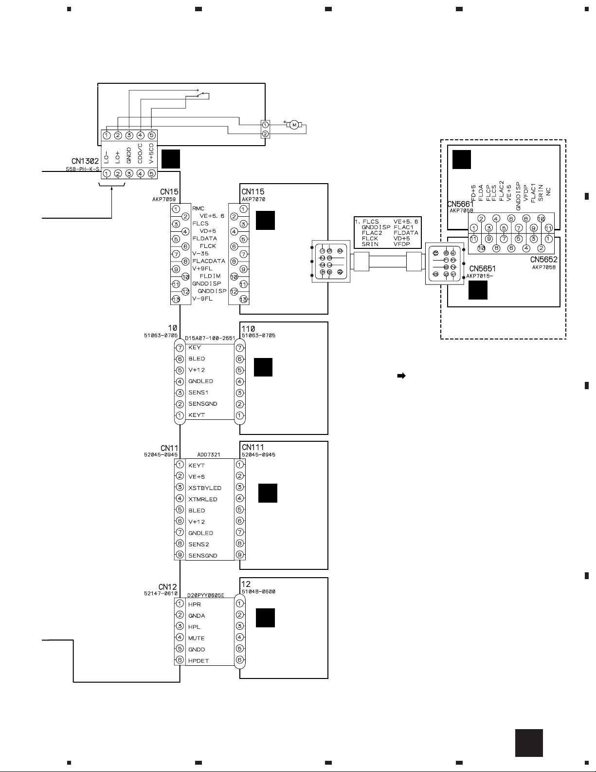
4. PCB CONNECTION DIAGRAM
5. PCB PARTS LIST
6. ADJUSTMENT
...............................................
....................................................
......................................
...............
.........................
...
10
22
30
34
2
3
7. GENERAL INFORMATION
7.1 DISASSEMBLY
7.2 PARTS
7.2.1 IC
7.2.2 DISPLAY
8. PANEL FACILITIES AND SPECIFICATIONS
..........................................................
............................................................
............................................
.................................................
................................
.......
37
37
40
40
43
44
PIONEER CORPORATION 4-1, Meguro 1-chome, Meguro-ku, Tokyo 153-8654, Japan
PIONEER ELECTRONICS SERVICE, INC. P.O. Box 1760, Long Beach, CA 90801-1760, U.S.A.
PIONEER ELECTRONIC NV Haven 1087, Keetberglaan 1, 9120 Melsele, Belgium
PIONEER ELECTRONICS ASIACENTRE PTE. LTD. 253 Alexandra Road, #04-01, Singapore 159936
c
PIONEER CORPORATION 2001
T – ZZR JUNE 2001 Printed in Japan
XC-L11
1. SAFETY INFORMATION
LITHIUM BATTERY NOTICE
WARNING!
Lithium batteries. Danger of explosion. Replacement must be done by
qualified personnel and only by following the instructions given in the
service manual.
This warning is stated on the product or in
the operating instructions. When replacing the
lithium batteries, follow the note below.
Dispose of the used battery promptly. Keep
away from children. Do not disassemble and
do not dispose of in fire.
The battery used in this device may present a
fire or chemical hazard if mistreated. Do not
recharge, disassemble, heat above 100°C or
incinerate. Replace only with the same Part
Number. Use of another battery may present a
risk of fire or explosion.
Note: The lithium battery installation po-
sition is shown in the exploded views.
LABEL CHECK
ADVARSEL!
Lithiumbatteri − Eksplosionsfare ved
fejlagtig håndtering. Udskiftning må
kun ske med batteri af samme fabrikat
og type. Levér det brugte batteri tilbage
til leverandøren.
Denne advarsel or angivet på produktet
eller i brugsvejledningen. Ved udskiftning
af lithium batterierne følges nedenstående
anveisning.
Batterierne må kun udskiftes med batterier af samme type og mærke.
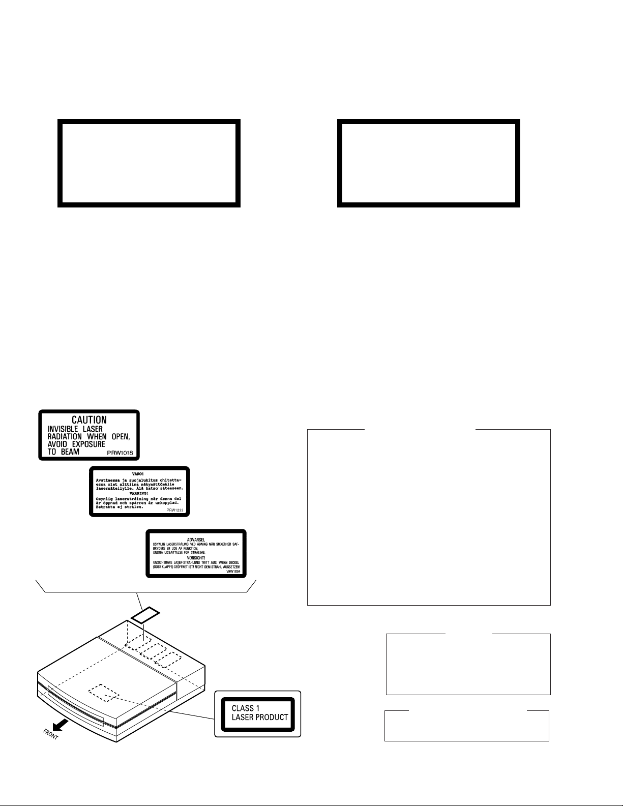
Additional Laser Caution
1. Laser Interlock Mechanism
The loading position detect switch (in CD mechanism
assembly) is set to "CLMP ON(CD CLOSE)" (ON:low
level,OFF:high level) position, the system control
IC(IC5501) get the "CLMP" signal, and hand the laser
"LDON" signal to IC1101.
Then a laser diode can be lighted except when the level of
signal CLMP is low.
The interlock also does not function in the test mode∗.
Laser diode oscillation will continue, if pin 1 of TA2150FN
(IC1101) on the RF AMP is connected to GND, or pin 19 is
connected to low level (ON), or else the terminals of
Q1101 are shorted to each other (fault condition).
2. When the cover is opened, close viewing of the objective
lens with the naked eye will cause exposure to a Class 1
laser beam.
∗ : Refer to page 34.
THIS PIONEER APPARATUS CONTAINS
LASER OF CLASS 1.
SERVICING OPERATION OF THE APPARATUS
SHOULD BE DONE BY A SPECIALLY
INSTRUCTED PERSON.
LASER DIODE CHARACTERISTICS
VRW-328
2
MAXIMUM OUTPUT POWER: 5 mW
WAVELENGTH: 780 – 785 nm
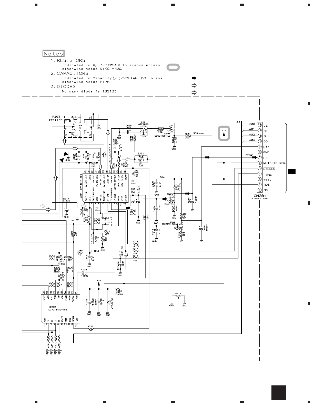
IMPORTANT
2. EXPLODED VIEWS AND PARTS LIST
NOTES:• Parts marked by "NSP" are generally unavailable because they are not in our Master Spare Parts List.
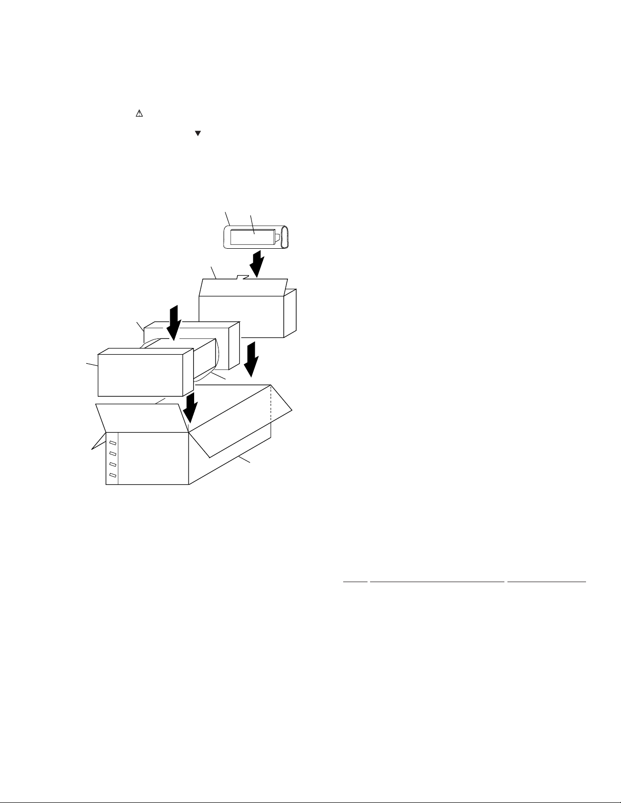
2.1 PACKING
The mark found on some component parts indicates the importance of the safety factor of the part.
•
Therefore, when replacing, be sure to use parts of identical designation.
Screws adjacent to mark on the product are used for disassembly.
•
XC-L11
6
4
3
2
FRONT
Refer to
1
"2.4 DISPLAY UNIT".
7
5
• PACKING PARTS LIST
Mark No. Description Part No.
1 DISPLAY UNIT AXX7107
2 Front Pad AHA7340
3 Rear Pad AHA7341
4 Spacer NS2001 AHB7056
5 Packing Case CD/Y AHD7988
6 Packing Sheet AHG7073
7 Seat Z23-007
3
XC-L11
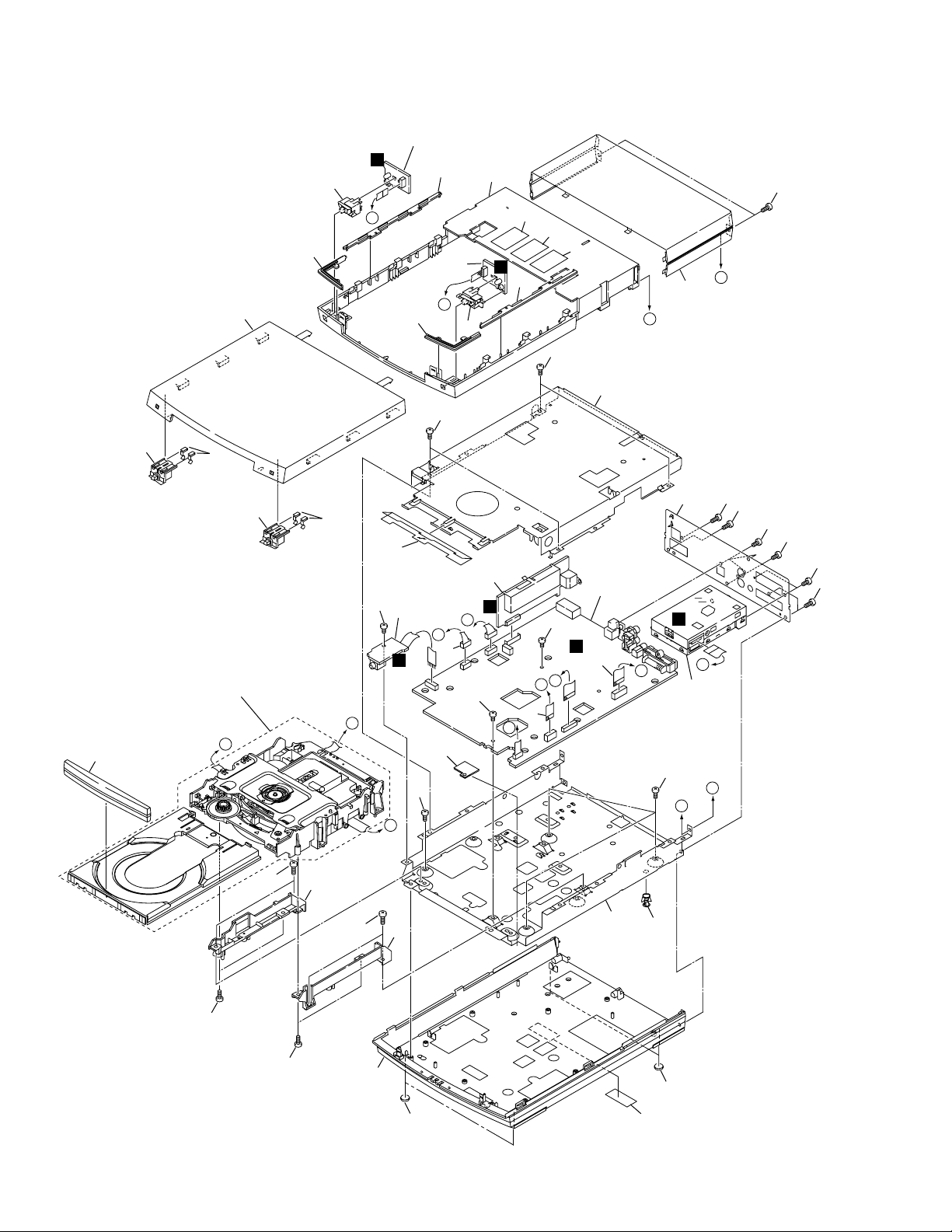
2.2 EXTERIOR
28
Refer to
"2.3 LOADING MECHANISM ASSY".
37
20
4
E
35
E
30
33
29
15
B
20
24
42
C
A
31
30
42
5
B
14
F
44
D
25
34
39
40
46
3
36
D
31
G
42
18
2
G
C
42
42
A
E
9
D
1
B
8
F
44
H
38
16
45
A
F
6
H
G
44
44
44
44
44
44
43
44
44
11
43
32
12
21
17
27
21
41
4

XC-L11
• EXTERIOR PARTS LIST
Mark No. Description Part No. Mark No. Description Part No.
1 MOTHER ASSY AWU7836
2 FLAC ASSY AWU7837
3 KEYR ASSY AWU7838
4 KEYL ASSY AWU7839
5 HP ASSY AWU7840
6 FM/AM TUNER MODULE AXQ7229
7 • • • • •
8 13P FFC/60V ADD7319
9 9P FFC/60V ADD7321
10 • • • • •
11 Adapter12 L ANW7231
12 Adapter12 R ANW7232
13 • • • • •
14 Connector Ass’y PG05KK-E07
NSP 15 Loading Mecha. Ass’y AXA7101
16 Rear Panel ANC8001
NSP 17 Bottom Plate ANF7027
NSP 18 Top Plate ANF7028
19 • • • • •
20 Sensor Plate ANG7360
NSP 41 Caution Label VRW-328
31 Side Line AAP7088
32 Bottom Base AMA7025
33 Top Panel 1 AMB7779
34 Top Panel 2 AMB7755
35 Button L Assy AXG7110
36 Button R Assy AXG7111
37 Tray Cap Assy AXG7112
38 Bonnet ANE7270
39 Caution Label PRW1018
40 Caution Label PRW1233
42 Screw BBZ30P060FMC
43 Screw BBZ30P100FMC
44 Screw BPZ30P080FZK
45 Screw PSC30P080FNI
46 Caution Label VRW1094
21 Leg AEB7090
22 • • • • •
23 • • • • •
24 Lead Barrier AEC7361
25 Wire Barrier AEC7379
NSP 27 PC Support VEC1749
26 • • • • •
28 Sensor Button L AAD7622
29 Sensor Button R AAD7623
30 Illuminate Lens AAK7896
5
XC-L11
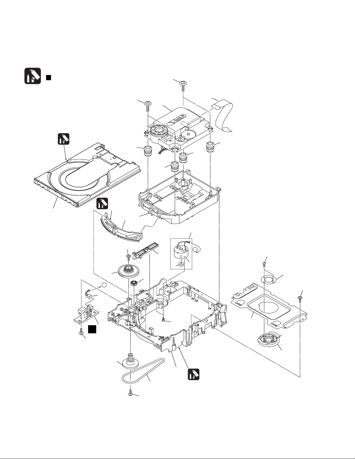
2.3 LOADING MECHANISM ASSY
Note :
Refer to
" Application of Lubricant".
25
23
Daifree
GEM1036
Lubricating Oil
GYA1001
15
A
7
13
22
25
8
12
16
17
2
8
3
5
4
6
8
8
A
24
18
22
19
27
20
22
C
1
14
9
22
21
11
Lubricating Oil
GYA1001
6

• LOADING MECHANISM ASSY PARTS LIST
Mark No. Description Part No.
XC-L11
Mark No. Description Part No.
NSP 1 LOAB Assy VWG2279
2 CD Traverse Mechanism VAM2202/03
3 Loading Motor Assy VXX2505
4 Motor Pulley PNW1634
5 Carriage DC Motor / 0.3W PXM1027
6 Flexible Cable (15P) ADD7317
7 Connector Assy 2P VKP2253
8 Float Rubber AEB7227
9 Belt VEB1330
10 • • • • •
11 Loading Base VNL1917
12 Float Base CD ANW7233
13 Drive Cam VNL1919
14 Gear Pulley VNL1921
15 Loading Gear VNL1922
16 Drive Gear VNL1923
17 SW Lever VNL1925
18 Clamper Plate CD ANB7261
19 Bridge VNE2252
20 Clamper CD ANW7234
21 Screw JGZ17P028FMC
22 Screw Z39-019
23 Tray VNL1920
24 Screw PBA1069
25 Screw ABA7069
26 • • • •
27 Clamp Magnet AMG7006
7
XC-L11
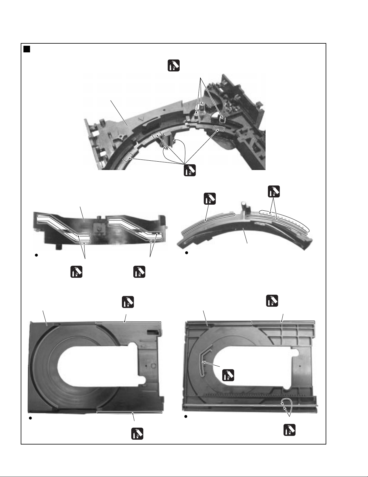
Application of Lubricant
Lubricating Oil
GYA1001
Around the shaft
No. 11
Loading Base
Lubricating Oil
GYA1001
Rear View
No. 23
Tray
No. 13
Drive Cam
Inner side of a ditch
Lubricating Oil
GYA1001
Inner side of a ditch
Lubricating Oil
GYA1001
Daifree
GEM1036
Concave of unevenness
Top View
No. 23
Tray
Lubricating Oil
GYA1001
Lubricating Oil
GYA1001
No. 13
Drive Cam
Daifree
GEM1036
Concave of unevenness
8
Top View
Concave of unevenness
Daifree
GEM1036
Bottom View
Inner side of a ditch
Daifree
GEM1036
Side of the rib
Daifree
GEM1036
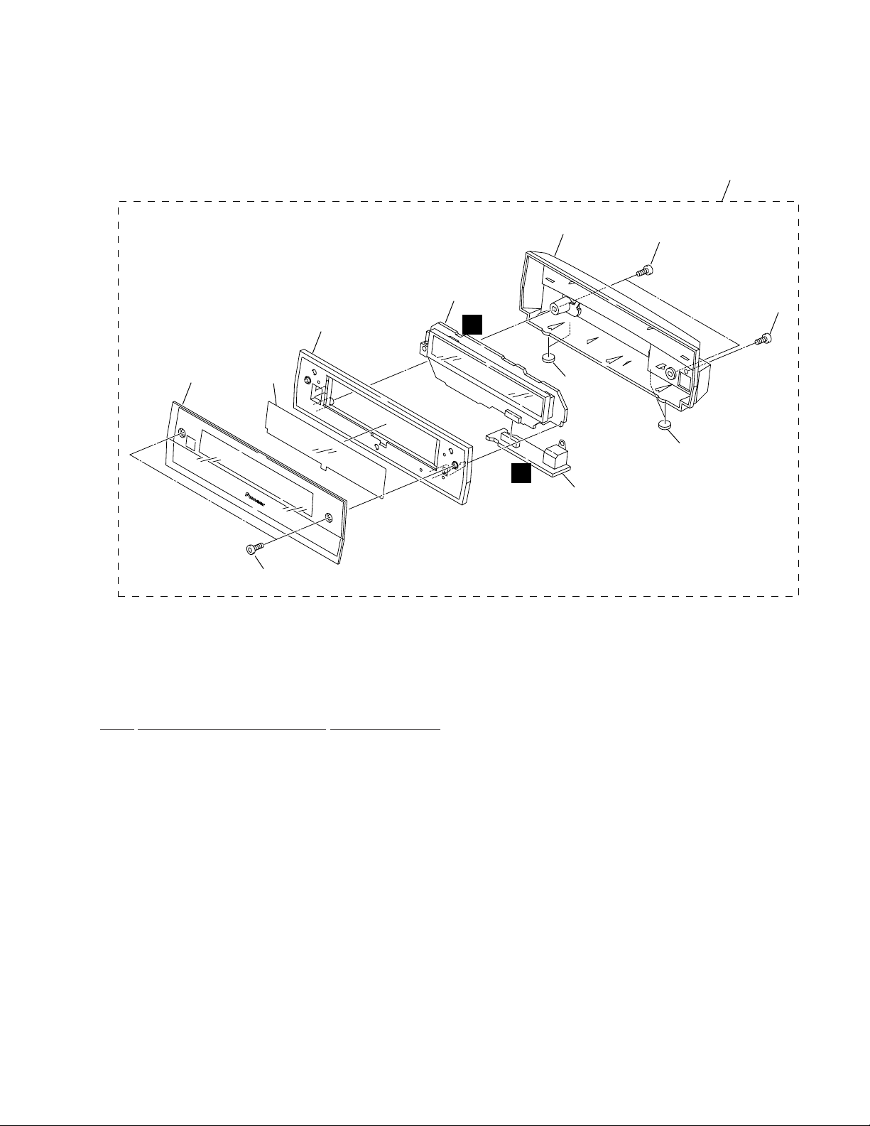
2.4 DISPLAY UNIT
XC-L11
11
8
1
7
4
6
H
3
9
10
3
I
2
5
• DISPLAY UNIT PARTS LIST
Mark No. Description Part No.
1 FLDP ASSY AWU7854
2 CNB ASSY AWU7855
3 Leg AEB7090
4 Window AAK7889
5 Deco Screw ABA7072
6 FL Filter AEC7195
7 Display Panel AMB7750
8 Display Cover AMC7048
9 Screw BPZ30P080FZK
10 Screw PSC30P080FNI
11 DISPLAY UNIT AXX7107
9
1
23
XC-L11
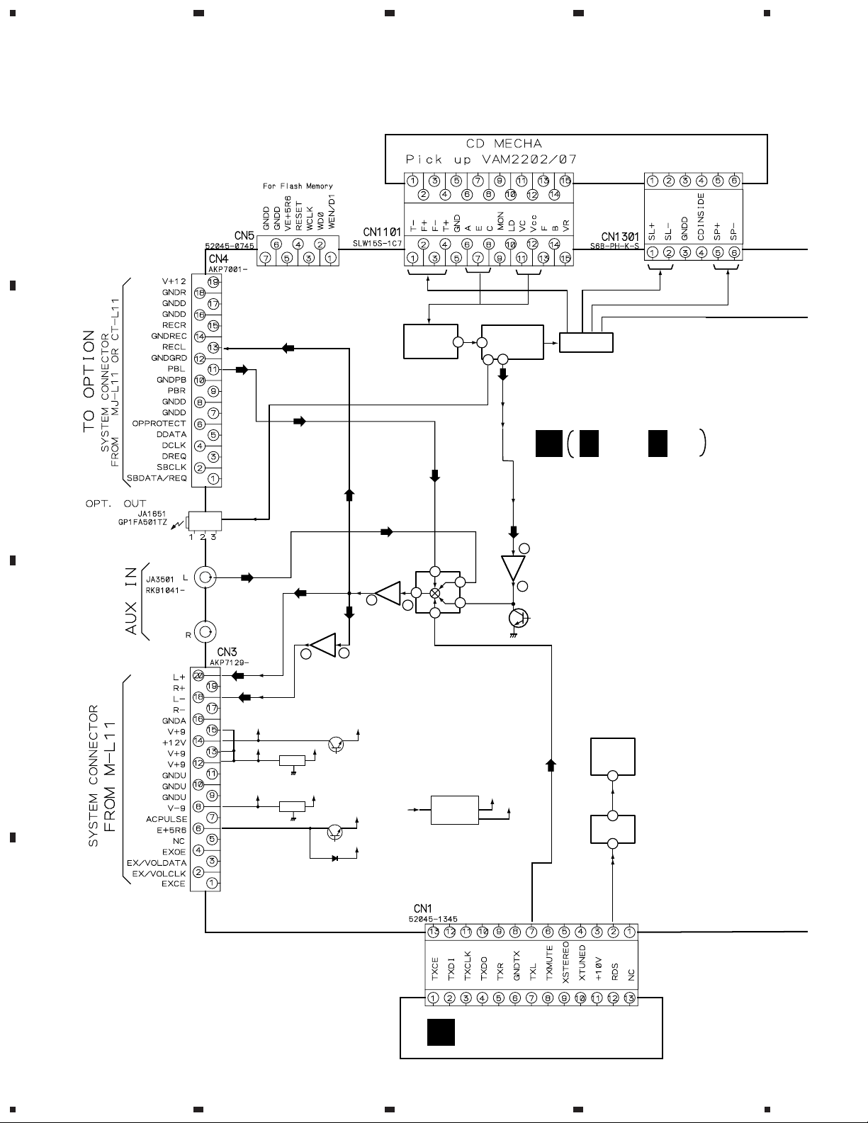
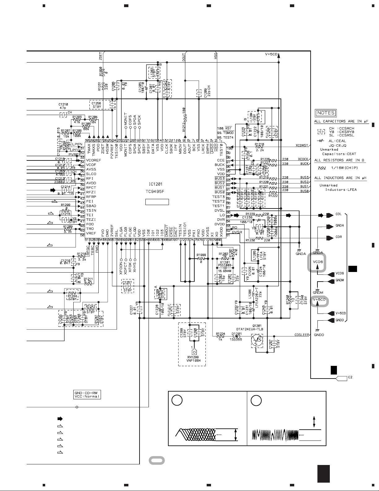
3. BLOCK DIAGRAM AND SCHEMATIC DIAGRAM
3.1 BLOCK DIAGRAM
A
SERVO
25
RF AMP.
IC1101
(TA2150FN)
DOUT
B
DSP
38
D/A
85
9
IC1201
(TC9495F)
4
LOADING MECHANISM
ASS'Y (AXA7101)
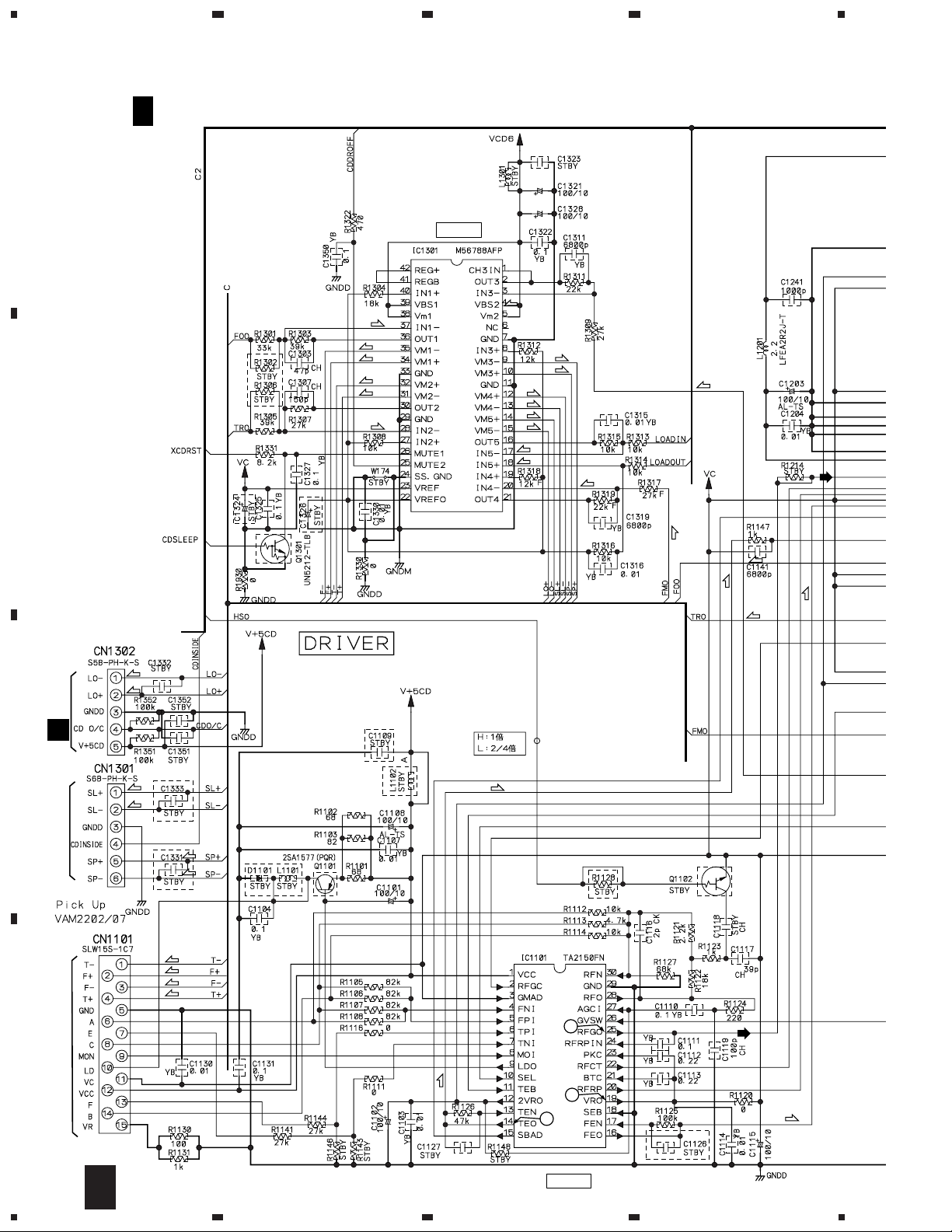
DRIVER
IC1301
(M56788FP)
B
B 1/3 - B 3/3
MOTHER ASS'Y
(AWU7836)
3
V-40
BALANCED
IC3504
(BA4558F)
1
CD MUTE
Q3503
AMP
µ-COM
6
(PDC079A)
2
RDS
4
(BU1923F)
IC5501
IC5701
FUNCTION
SW
15
14
12
11
IC3501
(BU4052BCF)
FLAC
IC551
Q551, Q552
D551-D556
VOLTAGE SUPPLY
for FL
V+9
V-9
13
5
7
IC3502
(BA4558F)
BALANCED
BUFFER(+)
5
7
IC3503
(BA4558F)
BALANCED
IC501
IC502
BUFFER(-)
V+5
Q501
V-5
Q5501
D5503
V+10
VE+5BU
VE+5
C
V+12
V+9
V-9
D
FM/AM TUNER MODULE
A
(AXQ7229)
10
1234
5
678
XC-L11
Note : When ordering service parts, be sure to refer to "EXPLODED VIEWS and PARTS LIST" or "PCB PARTS LIST".
S101
: VSK1011
CN602
CN601
S5B-PH-K
S2B-PH-K
LOADING
MOTOR
ASSY
: VXX2505
A
LOAB ASSY (VWG2279)
C
G
FLAC ASS'Y
(AWU7837)
D
KEYR ASS'Y
(AWU7838)
CN2
AKP7015
FLDP ASS'Y
H
(AWU7854)
CNB ASS'Y
I
(AWU7855)
DISPLAY UNIT
AXX7107
: AUDIO SIGNAL ROUTE
B
C
E
KEYL ASS'Y
(AWU7839)
F
HP ASS'Y
(AWU7840)
D
C
5
6
7
8
11
1
XC-L11
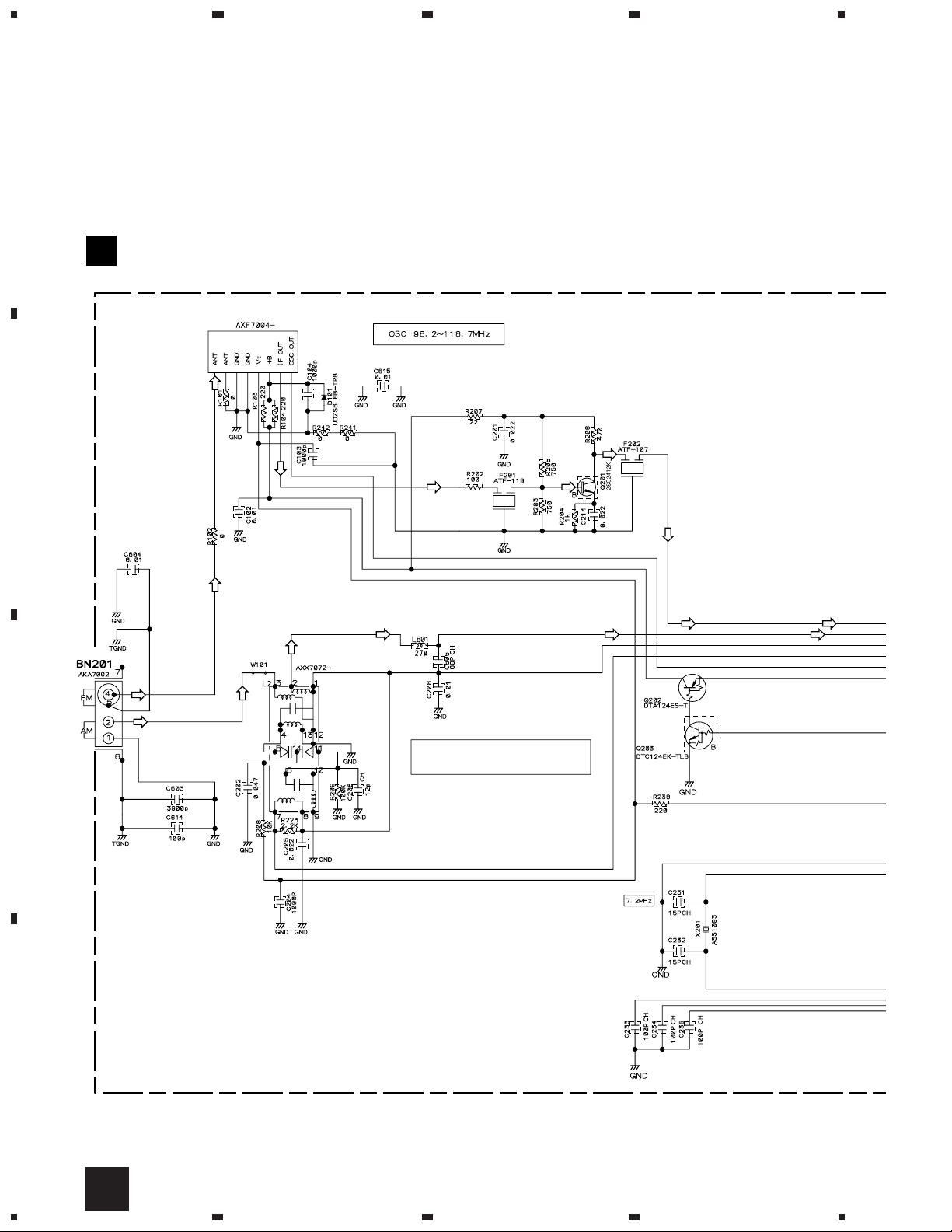
3.2 FM/AM TUNER MODULE
A
FM/AM TUNER MODULE (AXQ7229)
A
FM FRONT END
23
4
(FM)
(FM)
(FM)
(FM) (FM)
(AM)
(AM)
(FM)
MW RF TUNING BLOCK
(AM)
(FM)
(AM) (AM)
OSC : 981 - 2052kHz 9k step
B
(FM) (FM)
(FM)
(AM)
C
D
12
A
1234
(AM)
(AM)
5
678
XC-L11
A
: The power supply is shown with the marked box.
(TX)
: AUDIO SIGNAL ROUTE (TUNER)
(AM)
: AM SIGNAL ROUTE
(FM)
: FM SIGNAL ROUTE
(AM)
(AM)
(AM)
(FM)
(AM)
(AM)
(FM)
(TX)
(TX)
B
CN 1
2/3
B
(FM)
(AM)
(AM)
(TX)
(TX)
(FM)
(TX)
L201
ATE7003
C
D
A
5
6
7
8
13
1
XC-L11
3.3 MOTHER(1/3) ASSY
23
4
B 1/3
A
B
MOTHER(1/3) ASSY (AWU7836)
DRIVER
(F)
(F)
(F)
(T)
(T)
(T)
(C)
(C)
(L)
(T)
(S)
(S)
(S)
(L)
(L)
(C)
(S)
(C)
(F)
(T)
(T)
(L)
(L)
(F)
CN601
C
C
(C)
(C)
To CD MECHA
(S)
(S)
(F)
(T)
(T)
(F)
(T)
1
D
To CD PICK UP
14
1/3
B
1234
(T)
VC
2
RF AMP
(F)
5
678
XC-L11
A
B
(F)
(T)
(F)
(T)
DECODER
B 2/3
(C)
(S)
C
B 2/3
: CD AUDIO SIGNAL ROUTE
(F)
: FOCUS SERVO LOOP LINE
(T)
: TRACKING SERVO LOOP LINE
(S)
: SPINDLE SERVO LOOP LINE
(C)
: CARRIAGE SERVO LOOP LINE
(L)
: LOADING SERVO LOOP LINE
5
Note: The encircled numbers denote measuring point in the schematic diagram.
IC1101- Pin 25:
1
PLAY MODE (RF)
H : 500nsec/div
1.0Vp-p
VC
IC1101- Pin 14 :
2
TEST MODE,
Tracking Open (TRER)
H : 5msec/div
2.0Vp-p
VC
VC : IC1101- Pin19
: The power supply is shown with the marked box.
B
6
7
1/3
8
D
15
 Loading...