

Page 1
OPEN/
CLOSE
STEREO CD/VCD TUNER DECK
XC-IS22VCD
.
/
J
L
O
O
G
V
+
–
3
2
CD
D
O
L
B
Y
N
O
N
/
O
F
F
(
D
D
O
L
B
S
TAPE
P
E
S
T
I
D
ENHANCE
–
+
FOLDER/TRACK
G
T
N
U
I
N
N
I
U
N
T
G
·
·
¢
T
4
E
·
I
M
D
·
¡
E
O
R
1
M
/
E
C
S
L
O
R
E
S
C
V
T
K
.
E
M
A
R
D
E
M
E
J
S
O
U
R
A
Y
P
/
·
Y
TREBLE
S
BASS
A
T
L
O
P
P
7
TUNER
R
E
M
O
)
Y
B
N
R
LINE1.2
6
P
O
A
T
S
S
/
E
C
S
E
R
0
TAPE
F
RONTLO
OPEN/CLOSE
ADINGTRA
NISMDECK
Y
MECHA
T
U
O
2
E
IN
L
T
L
U
INE
2 IN
L O
TA
I
IG
D
CD/VCD TUNER DECK
XC-IS22VCD
THIS MANUAL IS APPLICABLE TO THE FOLLOWING MODEL(S) AND TYPE(S).
ORDER NO.
RRV2477
Type
Model
Power Requirement
Remarks
XC-IS22VCD
ZBDXJ O DC power supply from other system
ZLXJ/NC O DC power supply from other system
This product is a system(s) component.
This product does not function properly when independent; to avoid malfunctions, be sure
to connect it to the prescribed system component(s), otherwise damage may result.
Component
System
CD/VCD TUNER DECK XC-IS22VCD RRV2477 This service manual
DVD TUNER DECK XV-IS22DVD RRV2475
STEREO POWER AMPLIFIER M-IS22 RRV2482
SPEAKER SYSTEM S-IS22 RRV2461, RRV2487
Service Manual
Remarks
CONTENTS
1. SAFETY INFORMATION
2. EXPLODED VIEWS AND PARTS LIST
.......................................
.................
3. BLOCK DIAGRAM AND SCHEMATIC DIAGRAM 12
4. PCB CONNECTION DIAGRAM
5. PCB PARTS LIST
6. ADJUSTMENT
................................................
.....................................................
7. GENERAL INFORMATION
...........................
..................................
34
46
51
57
2
3
7.1 DIAGNOSIS
7.1.1 SEQUENCE AFTER THE POWER ON.57
7.1.2 SINGLE OPERATION METHOD
7.1.3 TROUBLE SHOOTING
7.1.4 DISASSEMBLY
7.2 PARTS
7.2.1 IC
8. PANEL FACILITIES AND SPECIFICATIONS
...................................................
...........
..........................
.....................................
..........................................................
...........................................................
.......
57
58
60
61
66
66
78
PIONEER ELECTRONIC CORPORATION 4-1, Meguro 1-chome, Meguro-ku, Tokyo 153-8654, Japan
PIONEER ELECTRONICS SERVICE, INC. P.O. Box 1760, Long Beach, CA 90801-1760, U.S.A.
PIONEER ELECTRONIC NV Haven 1087, Keetberglaan 1, 9120 Melsele, Belgium
PIONEER ELECTRONICS ASIACENTRE PTE. LTD. 253 Alexandra Road, #04-01, Singapore 159936
c
PIONEER ELECTRONIC CORPORATION 2001
T – ZZY JUNE 2001 Printed in Japan
Page 2
XC-IS22VCD
1. SAFETY INFORMATION
This service manual is intended for qualified service technicians; it is not meant for the casual
do-it-yourselfer. Qualified technicians have the necessary test equipment and tools, and have been
trained to properly and safely repair complex products such as those covered by this manual.
Improperly performed repairs can adversely affect the safety and reliability of the product and may
void the warranty. If you are not qualified to perform the repair of this product properly and safely, you
should not risk trying to do so and refer the repair to a qualified service technician.
THIS PIONEER APPARATUS CONTAINS
LASER OF CLASS 1.
SERVICING OPERATION OF THE APPARATUS
SHOULD BE DONE BY A SPECIALLY
INSTRCUTED PERSON.
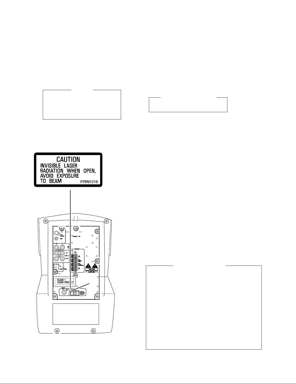
LABEL CHECK
IMPORTANT
LASER DIODE CHARACTERISTICS
MAXIMUM OUTPUT POWER: 5 mW
WAVELENGTH: 708-785 nm
Additional Laser Caution
1. Laser Interlock Mechanism
The loading position detect switch (in CD mechanism
assembly) is set to "CLMP ON(CD CLOSE)" (ON:low
level,OFF:high level) position, the system control
IC(IC5501) get the "CLMP" signal, and hand the laser
"LDON" signal to IC1101.
Then a laser diode can be lighted except when the level of
signal CLMP is low.
The interlock also does not function in the test mode∗.
Laser diode oscillation will continue, if pin 1 of TA2150FN
(IC1101) on the CD ASSY is connected to GND, or pin 10
is connected to low level (ON), or else the terminals of
Q1101 are shorted to each other (fault condition).
2. When the cover is opened, close viewing of the objective
lens with the naked eye will cause exposure to a Class 1
(Rear view)
laser beam.
∗ : Refer to page 54.
2
Page 3
XC-IS22VCD
2. EXPLODED VIEWS AND PARTS LIST
NOTES:• Parts marked by "NSP" are generally unavailable because they are not in our Master Spare Parts List.
The mark found on some component parts indicates the importance of the safety factor of the part.
•
Therefore, when replacing, be sure to use parts of identical designation.
Screws adjacent to mark on the product are used for disassembly.
•
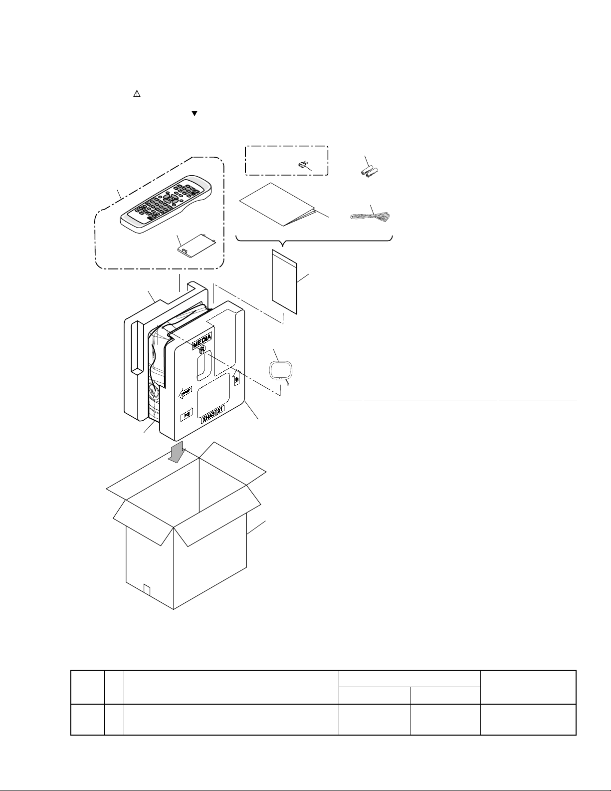
2.1 PACKING
ZBDXJ type only
16
O
+
E
D
I
E
7
R
INE1.2
L
R
Y
E
A
M
L
U
L
O
P
V
S
I
D
R
E
E
P
M
M
I
D
N
/O
Y
B
D
N
V
/
M
V
U
T
L
E
+
–
O
D
D
L
V
N
E
O
V
U
N
M
T
O
N
S
A
N
+
–
H
R
C
U
T
T
F
V
I
R
E
T
R
E
H
S
D
L
–
E
O
T
F
V
X
STEP
E
T
N
+
3
W
E
O
T
L
¢
M
A
R
10/0
C
B
P
M
>10
A
E
L
6
C
DIGEST
3
O
E
N
2
U
T
P
E
T
P
C
A
E
T
IR
D
D
A
T
D
C
A
T
S
U
S
1
E
M
S
U
G
A
O
P
R
P
P
CT
23
E
O
T
EL
S
S
7
¡
4
O
S
D
U
O
N
I
V
A
E
R
–
R
P
H
T
89
C
A
R
A
PE
E
S
RE
E
5
M
M
7
I
O
E
T
M
N
T
O
S
M
A
L
4
P
E
E
L
S
1
C
4
15
10
11
8
1
13
12
6
14
(1) PACKING PARTS LIST
Mark No. Description Part No.
1 FM Antenna ADH7004
2 • • • • •
3 • • • • •
4 Operating Instructions XRE3043
(English/ Chinese/ Spanish)
5 • • • • •
6 AM Loop Antenna ATB7009
7 Remote Control Unit XXD3035
NSP 8 Dry Cell Batteries(AA/R6) VEM-013
9 • • • • •
NSP 10 Polyethylene Bag Z21-038
(0.03 x 230 x 340)
11 Protector L XHA3120
12 Protector R XHA3121
13 Packing Sheet AHG7053
14 Packing Case M See Contrast table (2)
15 Battery Cover XZN3116
16 Power Plug Adapter See Contrast table (2)
(2) CONTRAST TABLE
XC-IS22VCD/ZBDXJ and XC-IS22VCD/ZLXJ/NC are constructed the same except for the following:
Mark
No.
Symbol and Description
ZBDXJ type ZLXJ/NC type
14 Packing Case M XHD3176 XHD3177
16 Power Plug Adapter XKM3002 Not used
Part No.
Remarks
3
Page 4
XC-IS22VCD
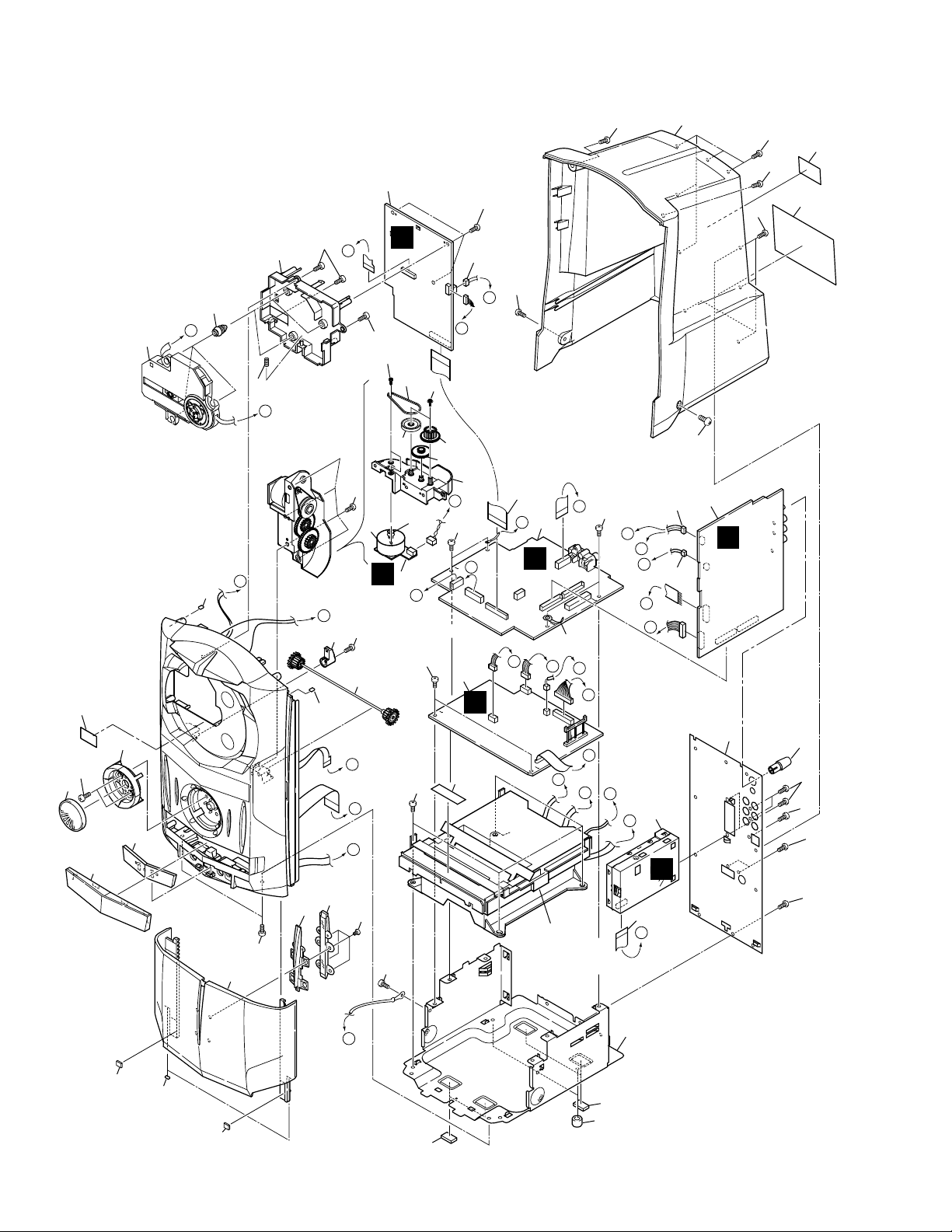
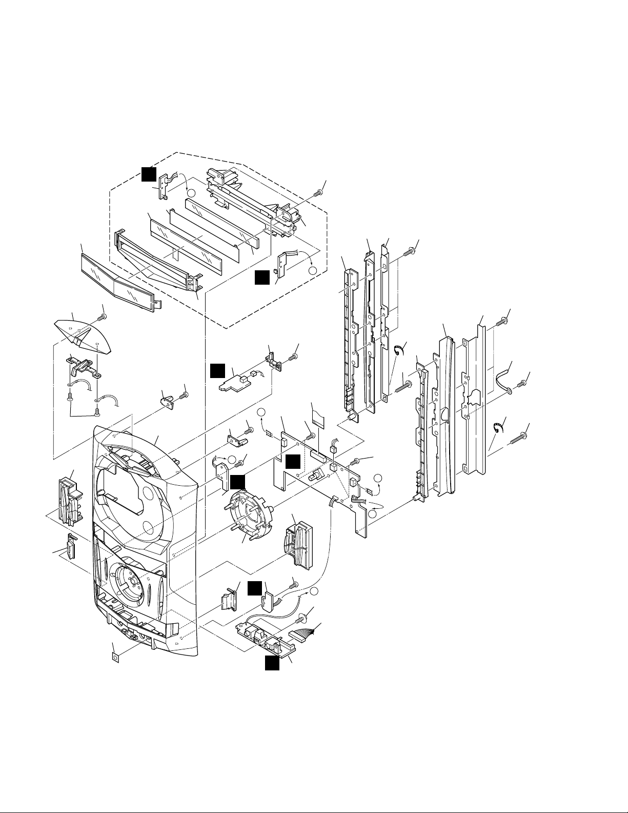
2.2 EXTERIOR
N
13
39
28
51
35
30
36
22
20
37
52
38
54
40
52
5
54
44
29
52
52
52
F
17
54
O
M
N
50
21
26
49
24
54
18
M
25
52
C
G
27
4
B
14
F
D
52
23
34
22
B
48
A
C
A
48
46
B
O
48
9
L
3
E
A
B
48
D
E
F
G
C
11
10
2
C
53
K
J
6
E
41
I
H
15
G
K
J
I
1
H
42
52
47
52
A
54
48
16
33
45
48
12
Refer to "2.4, 2.5
DECK MECHANISM UNIT
(1/2 and 2/2)".
L
7
32
31
55
P
22
19
55
31
4
Page 5

(1) EXTERIOR PARTS LIST
XC-IS22VCD
Mark No. Description Parts No.
1 FM/AM TUNER MODULE AXQ7228
NSP 2 AF ASSY XWZ3464
NSP 3 IF ASSY XWZ3465
NSP 4 CD MOTOR ASSY XWZ3410
5 CD ASSY XWP3002
NSP 6 DECK ASSY XWX3038
7 13p F.F.C/30V XDD3081
8 • • • • •
9 Flexible Cable 30p XDD3079
10 Connector Assy PG02KK-F15
11 Connector Assy 3p XDX3016
12 Deck Mechanism Unit AXA7075
13 CD Mecha KSM-900AAA
14 Slider Motor VXM1033
15 Rear Panel(Mtl) XNC3095
16 CD Door Lens XAK3188
17 Connector Ass'y PG02KK2F07
18 Float Spring ABH7170
NSP 19 Spacer AEB7092
20 Float Rubber AEB7129
21 Belt AEB7171
22 Cussion Rubber AEB7154
23 Shaft Holder (Pls) AMR7237
24 Gear B AMR7260
25 Gear A ANW7063
Mark No. Description Parts No.
26 Gear Pulley A ANW7066
27 Motor Pulley PNW1634
28 Play Button (Pls) XAD3097
29 Float Base CD (Pls) XMR3020
30 Jack Door(Pls) XAN3030
31 Rubber Sheet AEB1111
NSP 32 Chassis M(Mtl) XNA3007
33 LT Conductor M (Pls) XAK3217
34 Shaft Assy XXG3076
35 Jog Knob(Pls) XAA3018
36 Tray Cap (Pls) XAK3191
37 CD Door(Pls) XAN3039
38 Rear Cover (Pls) XMC3001
39 Pu Caution Label ARW7059
40 Caution Label PRW1018
NSP 41 Tray Seal RRW1162
42 Mic Knob (Pls) XAB3007
NSP 43 Label VRW1629
44 Name Label See Contrast table (2)
45 Screw M3 (Steel) XBA3005
46 Gear Holder (Pls) AMR7240
47 Screw BMZ30P060FZK
48 Screw BBZ30P080FMC
49 Screw Z39-019
50 Screw PMZ26P040FMC
51 Screw PPZ30P080FMC
52 Screw VPZ30P080FZK
53 Cord Clamper (steel) RNH-184
54 Screw BBZ30P080FZK
55 Spacer XEB3023
(2) CONTRAST TABLE
XC-IS22VCD/ZBDXJ and C-IS22VCD/ZLXJ/NC are constructed the same except for the following:
Mark
No.
Symbol and Description
ZBDJ type ZLXJ/NC type
Part No.
Remarks
44 Name Label XAL3080 XAL3081
5
Page 6
XC-IS22VCD
2.3 FRONT PANEL ASSY
14
36
17
10
18
34
38
41
15
28
22
B
33
J
6
8
A
37
20
K
5
16
42
33
30
34
32
24
21
34
26
D
27
34
9
1
41
I
25
19
7
A
34
34
C
M
4
11
C
42
23
32
41
B
12
39
6
29
13
L
34
3
P
31
35
H
2
Page 7

÷ FRONT PANEL ASSY PARTS LIST
Mark No. Description Parts No.
NSP 1 FRONT PANEL ASSY XWZ3408
NSP 2 F-TERMINAL ASSY XWZ3487
NSP 3 CD OPEN SW ASSY XWZ3411
NSP 4 CD CLOSE SW ASSY XWZ3412
NSP 5 LIGHT- L ASSY XWZ3413
NSP 6 LIGHT- R ASSY XWZ3414
NSP 7 MEDIA BLUE LED ASSY XWZ3415
8 LCD ASSY XAV3012
9 17p F.F.C/30V XDD3082
10 Func. Button L (Pls) XAD3080
11 Func. Button R (Pls) XAD3081
12 Side Button L (Pls) XAD3082
13 Side Button R (Pls) XAD3083
14 O/C Key(Pls) XAD3084
15 Frame L (Mtl) XNG3048
16 Frame R (Mtl) XNG3049
17 O/C Key Base (Pls) XAK3189
18 Display Window (Pls) XAK3190
19 PCB Holder(Pls) XMR3030
20 Lens M(Pls) XAK3192
XC-IS22VCD
21 Front Panel CD (Pls) XMB3054
22 Blind L(Pls) XMR3023
23 Blind R(Pls) XMR3025
24 R.C. Holder L (Pls) XMR3039
25 R.C. Holder R (Pls) XMR3040
26 LCD Cover (Pls) XAK3233
27 Rail R(Pls) XMR3024
28 Rail L(Pls) XMR3022
29 Ring Button (Pls) XAD3098
30 Cord Clamper (Steel) RNH-184
31 Screw With Washer ABA1005
32 Screw (P3 x 20) XBA3006
33 Screw IPZ30P100FMC
34 Screw VPZ30P080FZK
35 Connector Assy 12p XDX3014
36 Screw BPZ30P060FZK
37 Diffusion Sheet XAK3234
38 Lens Holder XMR3028
39 Sensor Cover XAK3270
40 Screw BBZ30P060FZK
41 Screw VPZ30P100FMC
42 Binder ZCA-SKB90BK
7
Page 8
XC-IS22VCD
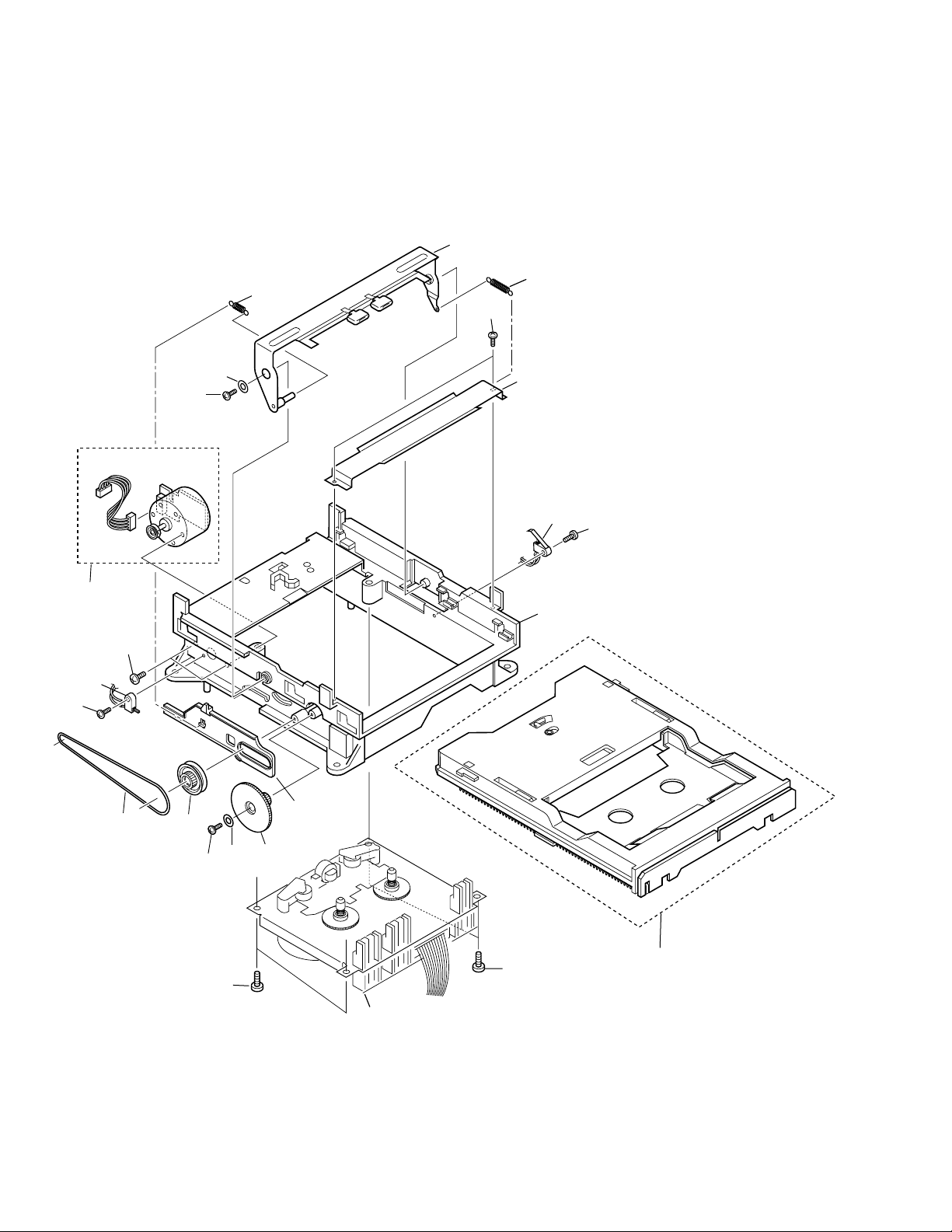
2.4 DECK MECHANISM UNIT (1/2)
17
6
5
16
16
14
13
12
4
16
1
11
9
3
18
16
8
4
16
8
10
2
2
Refer to "2.5 DECK MECHANISM UNIT (2/2)".
7
Page 9

÷ DECK MECHANISM UNIT (1/2) PARTS LIST
Mark No. Description Parts No.
1 Screw FG114-14
2 Screw UG12H-15
3 Front BKT FC64K-11
4 Washer MJ112-22
5 SP Return FK34N-11
6 Plate Hold BLK F573-258
7 Holder CST BLK F527-078
8 LDG Base FD56R-12
9 Pulley FD56T-11
10 LDG Gear FD56U-11
11 Slider FD57E-11
12 LDG Belt FF19L-12
13 Switch UE15S-14
14 MTR Reel BLK F564-313
15 ...............
16 Screw UG12H-28
17 SP Clamper FK34M-11
18 Switch UE18P-21
XC-IS22VCD
9
Page 10
XC-IS22VCD
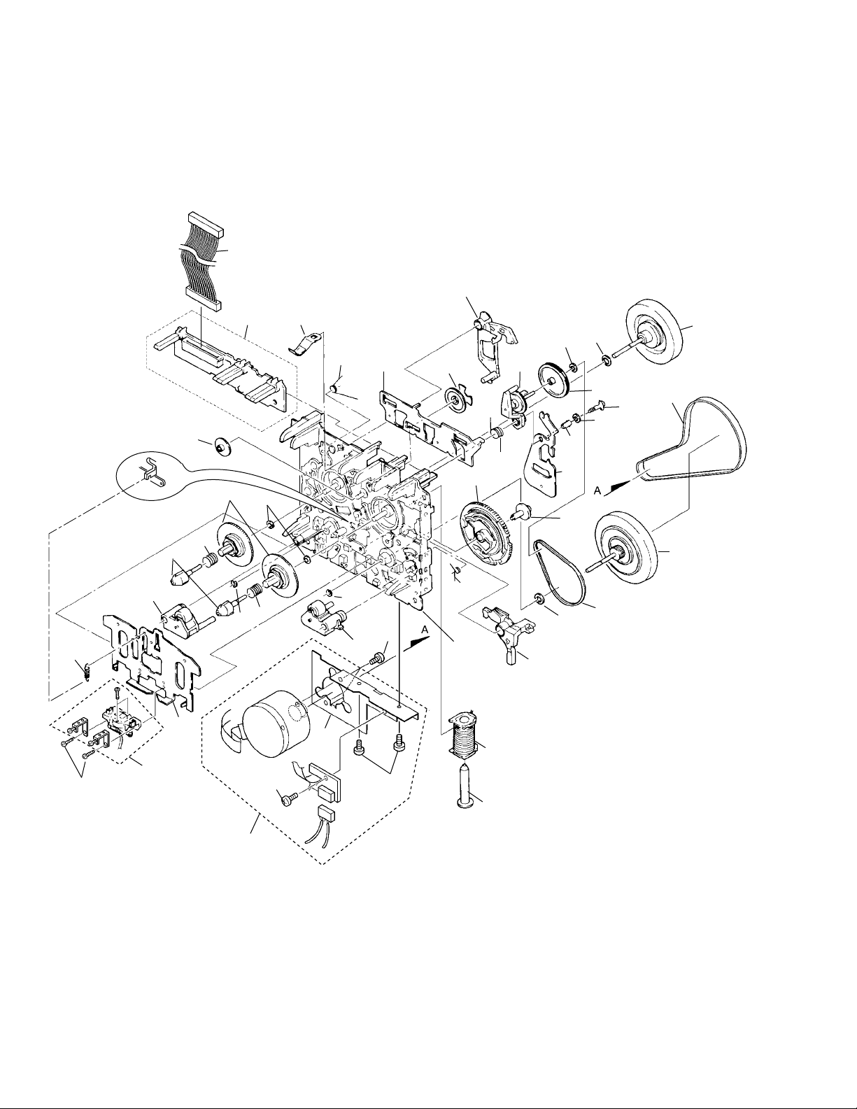
2.5 DECK MECHANISM UNIT (2/2)
39
33
40
19
15
12
10
4
2
32
8
30
23
5
14
31
32
7
3
18
34
11
6
16
35
21
13
30
24
41
42
43
37
36
26
20
27
22
10
17
28
1
1
29
9
25
3
38
Page 11

÷ DECK MECHANISM UNIT (2/2) PARTS
LIST
Mark No. Description Parts No.
1 Screw KG194-36
2 Reel Feather FD57D-13
3 Screw UG11S-14
4 SP Reel(L) FK32U-12
5 SP Brake FK33B-13
6 SP Arm Play FK33P-11
7 SP Reel(R) FK32V-12
8 Spring Cassette FC65M-11
9 BKT MTR FC64M-12
10 Reel Base FD52W-12
11 Cam Gear FD52Y-23
12 Play Gear (A) FD53K-12
13 Arm Play FD53D-19
14 Plate Slide FC61L-19
15 PCB Control BLK F567-617
16 Chassis base BLK F612-231
17 Head Base FC61K-32
18 Roller Pinch BLK R F514-129
19 Roller Pinch BLK L F514-130
20 Assy F/W FR24S-21
XC-IS22VCD
21 Clutch Assy BLK F522-037
22 Clutch Assy BLK F522-048
23 Washer FJ111-13
24 F/R Pulley FD53F-15
25 Solenoid BLK F765-279
26 F/R Belt FF18W-12
27 Belt Main FF19H-11
28 Plate HD BLK F513-824
29 MTR MAIN BLK F525-321
30 Washer FJ111-30
31 Washer FJ111-35
32 Washer UJ16F-11
33 Lever Brake FD53P-17
34 FF Gear(A) FD53L-12
35 Cam SP FK32S-14
36 Screw UJ14A-12
37 Lever F/R FC62G-14
38 Plunger FL41S-21
39 Mecha-Cable WH65N-11
40 Spring HB FK32T- 31
41 Screw UG15V-13
42 Washer MJ112- 22
43 Spacer UJ15V- 13
11
Page 12
1
234
XC-IS22VCD
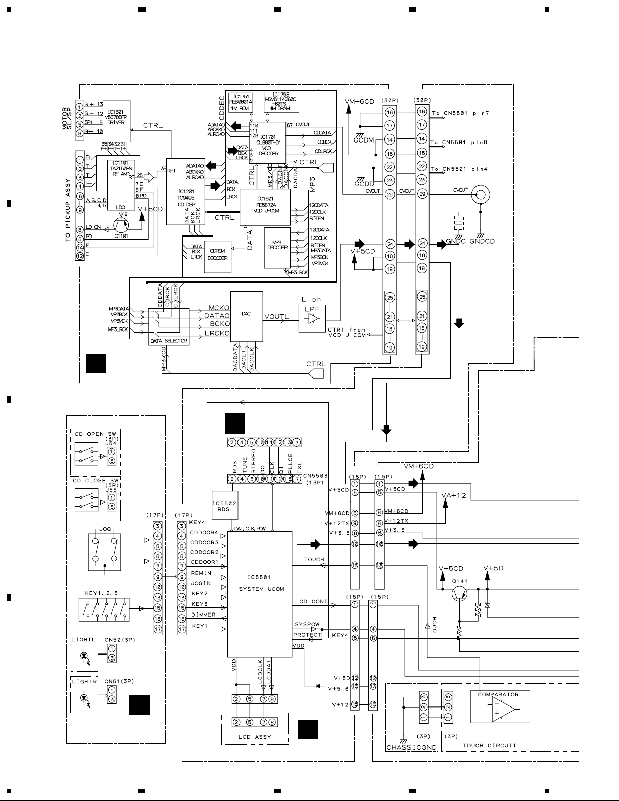
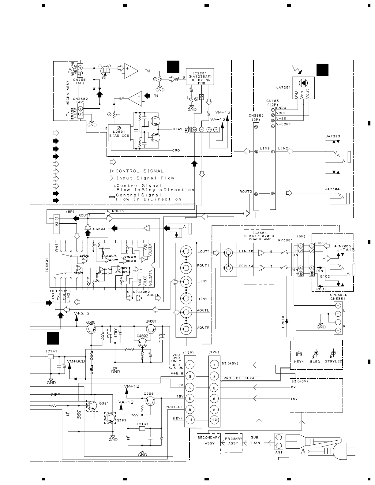
3. BLOCK DIAGRAM AND SCHEMATIC DIAGRAM
3.1 BLOCK DIAGRAM
CN1201 CN5505
A
(CD)
(CD)
(CD)
(CD)
(CD)
B
CD ASSY
F
FM/AM TUNER
A
C
CN5504CN52
MODULE
CN5501
CN3004
(CD) (CD)
(CD)
(CD)
(CD)
(TX)
CN3003
CN5502
D
(TX)
TOUCH ASSY
I
12
FRONT PANEL
ASSY
B
IF ASSY
1234
CN101CN101
Page 13
5
67
8
XC-IS22VCD
SIGNAL ROUTE
(PB)
: PB SIGNAL
(REC)
: RECORDING SIGNAL
(TX)
: AUDIO SIGNAL (TUNER)
(CD)
: CD SIGNAL
(L1)
: LINE 1 SIGNAL
(L2)
: LINE 2 SIGNAL
(LO1)
: LINE OUT 1 SIGNAL
(LO2)
: LINE OUT 2 SIGNAL
(MIC)
: MIC IN SIGNAL ROUTE
: AUDIO SIGNAL ROUTE
CN3006
RECL
PBL
(REC)
(PB)
(LO2)
(LO1)
(PB)
(REC)
: RF SIGNAL
(MIC)
IC3901
(REC)
E
(PB)
(MIC)
DECK ASSY
PBL
RECL
(PB)
(REC)
JA3901
JA7105
(L2)
(PB)
(L2)
(LO2)
(LO2)
JA3333 CN3104
(L2)
H
F-TERMINAL
ASSY
H.P. ASSY
(LO2)
A
B
(CD)
C
(L2)
(L1) (L1)
(TX)
AF ASSY
(L1)
(L1)
(LO1)(LO1)
(LO1)
(L1)
C
M-IS22CD
(STEREO POWER AMPLIER)
CN3332CN3001
BLED ASSY
POWER SUPPLY ASSY
D
13
5
6
7
8
Page 14
1
234
XC-IS22VCD
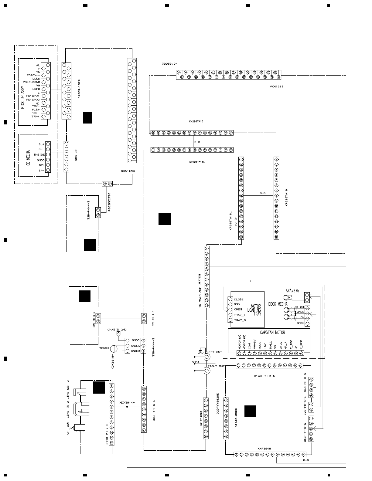
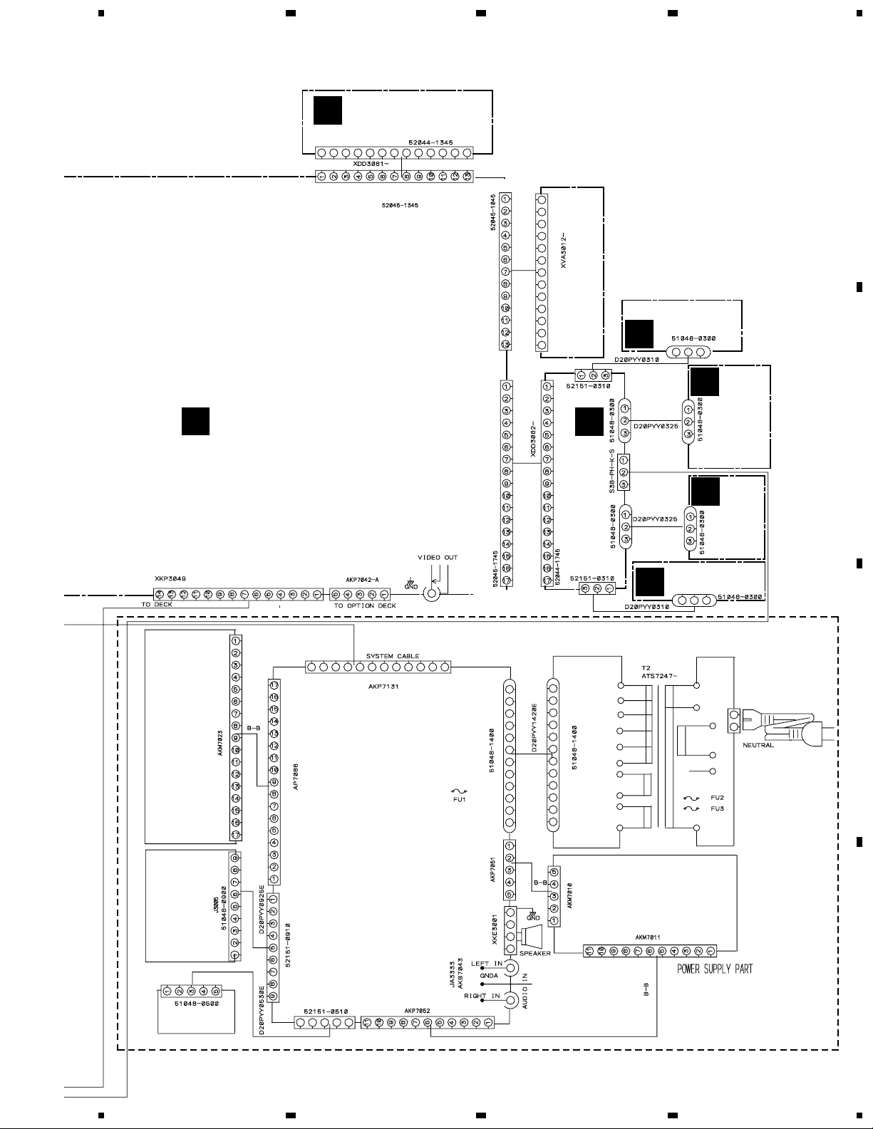
3.2 OVERALL CONNECTION DIAGRAM
CD MECHA ASSY
(KSM-900AAA)
A
CN1101
CN5505
F
CN1301
B
(XWZ3410)
G
CD MOTOR ASSY
- 3/3
1/3
CD ASSY
(XWP3002)
S2B-PH-SM3
CN1302
CN11
CN1201
C
CN5502
CN3003
CN5501
AF ASSY
(XWZ3464)
CN3004
C
D
14
1234
D
CN8001
(XWZ3415)
LED ASSY
MEDIA BLUE
H
(XWZ3487)
F-TERMINAL ASSY
CN103
CN101 CN3008
CN3005
CN3001
CN3006
J2201
CN2701
DECK ASSY
E
(XWX3038)
CN2202
CN2301CN2302CN2603
Page 15
5
67
8
XC-IS22VCD
Note : When ordering service parts, be sure to refer to "EXPLODED VIEWS and P AR TS LIST" or "PCB PARTS LIST".
FM/AM TUNER
A
MODULE
(AXQ7228)
CN201
A
B
IF ASSY
(XWZ3465)
CN5507CN5506
CN5503
CN5509
CN5504
LCD ASSY
CN50
I
CN49
(XWZ3408)
FRONT PANEL ASSY
CN51
CN52
J51
LIGHT-R ASSY
(XWZ3414)
J
J50
L
J54
M
J55
LIGHT-L ASSY
(XWZ3413)
K
ASSY
(XWZ3411)
CD OPEN SW
(XWZ3412)
SW ASSY
CD CLOSE
B
CN3002
POWER SUPPLY ASSY
BLUE LED
ASSY
J3004
H.P. ASSY
5
CN3332
MAIN AMP ASSY
CN3102
M-IS22
(STEREO POWER AMPLIFIER)
Service Manual
order no. RRV2482
CN3105
CN3104 CN3106
6
J3001
CN3103CN3331
J3001
SECONDARY
CN3303
7
C
ASSY
AMP ASSY
CN3008
D
15
8
Page 16
1
XC-IS22VCD
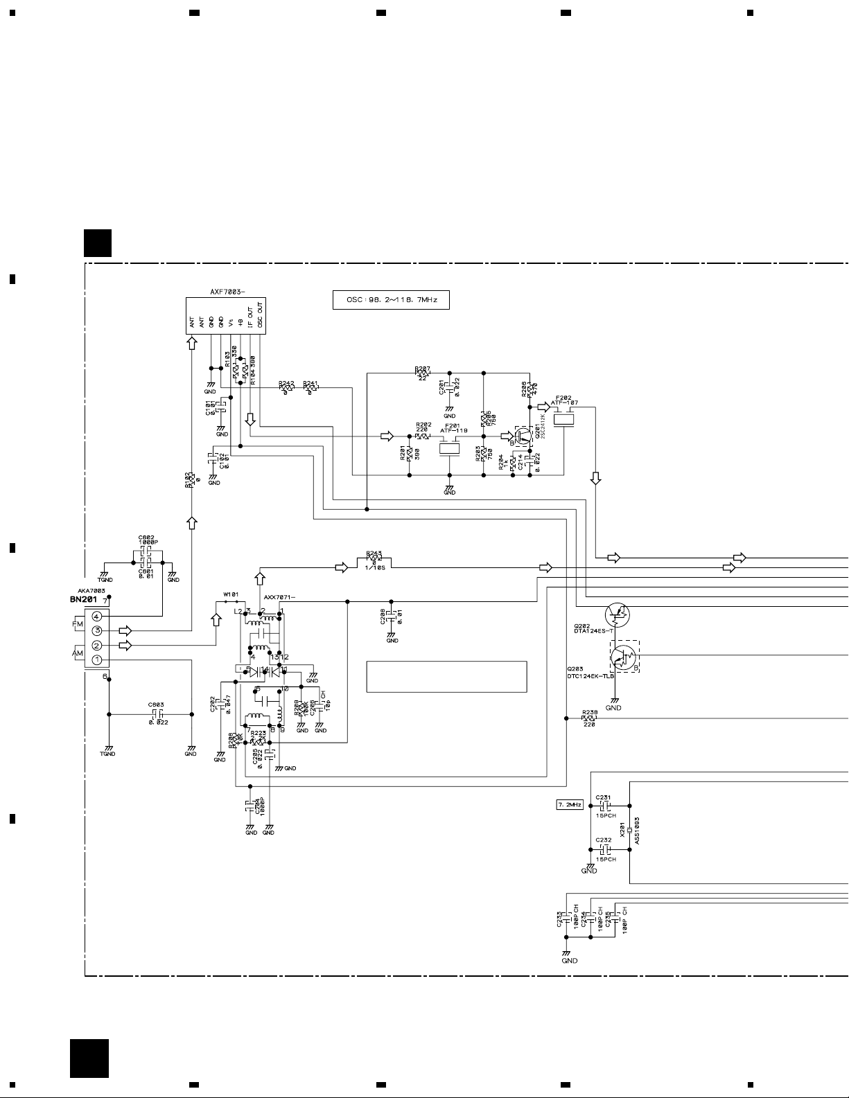
3.3 FM/AM TUNER MODULE
A
FM/AM TUNER MODULE (AXQ7228)
A
FM FRONT END
234
(FM)
(FM)
(FM)
(FM) (FM)
(AM)
(AM)
(FM)
MW RF TUNING BLOCK
(AM)
(FM)
(AM) (AM)
OSC : 981 - 2052kHz 9k step
B
(FM) (FM)
(FM)
(AM)
C
D
16
A
1234
Page 17
(AM)
5
(AM)
(AM)
(AM)
(AM)
(FM)
(AM)
67
: The power supply is shown with the marked box.
(TX)
: AUDIO SIGNAL ROUTE (TUNER)
(AM)
: AM SIGNAL ROUTE
(FM)
: FM SIGNAL ROUTE
(AM)
(FM)
(TX)
8
XC-IS22VCD
(TX)
A
B
CN5503
B
(FM)
(AM)
(AM)
(FM)
L201
ATE7003
(TX)
(TX)
(TX)
CN201
C
D
A
5
6
7
8
17
Page 18
XC-IS22VCD
3.4 IF ASSY
A
1
234
(D)(D)
IF ASSY
B
(XWZ3465)
A
(D)
CN5503
CN201
CN5501
(CD)
B
CN3004
C
CN5502
(D)
(TX)
(D)
(CD)
(TX)
(CD)
CN3003
C
C
CN5504
D
I
CN52
18
B
1234
Page 19
5
67
8
XC-IS22VCD
VIDEO OUT
JA5001
(D)(D)
R5653
(CD) (CD)
C5577
100p
: The power supply is shown with the marked box.
L5652
VTL1084
CN5505
(D)
(CD)
(D)
CN5506
CN1201
3/3
F
A
B
CN5509
SIGNAL ROUTE
(CD)
: CD AUDIO SIGNAL ROUTE
(TX)
: AUDIO SIGNAL ROUTE (TUNER)
(D)
: DIGITAL SIGNAL ROUTE
: VIDEO SIGNAL ROUTE
CN2202
E
CN5507
C
CN5511
To. Option Deck
D
5
6
7
8
B
19
Page 20
1
234
XC-IS22VCD
3.5 AF and MIDIA BLUE LED ASSYS
A
(LO1)
(LO1)
(MIC)
(LO1)
(L1)
(L1)
(REC)
(L2)
(MO)
(L1)
(MO)
(TX)
(REC)
B
CN3006
J2201
E
(PB)
(PB)
(REC)
(REC)
(CD) (CD)
(L2)
(LO2)(LO2)
(MIC)(MIC)
(MO)
CN3008
CN8001
(TX)
C
(XWZ3415)
MEDIA BLUE LED ASSY
(TX)
D
TOUCH ASSY
CN101
D
CN3004
(CD)
(TX)
NC
20
B
CN5501
C
D
1234
Page 21
(L2)
5
67
8
XC-IS22VCD
H
CN103
NCNCNC
CN3005
(L2)
: The power supply is shown with the marked box.
AF ASSY
C
(XWZ3464)
BA4558F
MAIN MIC
(MIC)
A
(MIC)
(MO)
(LO2)
(MO)
(MIC)
(LO2)
(MO)
(LO2)
(L2)(L2)
(MIC)
SIGNAL ROUTE
(PB)
: PB SIGNAL
(REC)
: RECORDING SIGNAL
(TX)
: AUDIO SIGNAL (TUNER)
(CD)
: CD SIGNAL
(L1)
: LINE 1 SIGNAL
(L2)
: LINE 2 SIGNAL
(LO1)
: LINE OUT 1 SIGNAL
BA4558F
(MIC)
(LO2)
(MO)
(MIC)
(MIC)
: LINE OUT 2 SIGNAL
: MAIN OUT SIGNAL
: AUDIO SIGNAL ROUTE
: MIC IN SIGNAL ROUTE
CN3001
To. M-IS22
B
B
CN3003
(Stereo power amplifier)
C
1SS355
D
B
CN5502
5
6
7
8
C
21
Page 22
1
XC-IS22VCD
3.6 DECK ASSY
A
CN2301
DECK ASSY
E
(XWX3038)
234
(PB)
(PB)
(PB)
CN2302
B
C
(REC)
(REC)
SIGNAL ROUTE
(PB)
: PB SIGNAL
(REC)
: RECORDING SIGNAL
(PB)
(REC)
(REC)
D
22
E
1234
Page 23
5
67
8
XC-IS22VCD
: The power supply is shown with the marked box.
A
J2201
(PB)
(PB)
CN3006
(REC)
C
(REC)
(PB)
(PB)
(PB)
(REC)
CN2202
B
(REC)
CN5506
B
C
CN2701
CN2603
D
5
6
7
8
E
23
Page 24
1
234
XC-IS22VCD
3.7 CD (1/3) and CD MOTOR ASSYS
A
F 1/3
G
CD MOTOR ASSY
(XWZ3410)
B
CD ASSY
(XWP3002)
CN11
(TS)
(FS)
(FS)
(FS)
(FS)
(TS)
(FS)
(TS)
(FS)
(TS)
(TS)
6.7V
(CM)
(LM)
(LM)
(CM)
(SM)
(SM)
(CM)
(LM)
(SM)
(LM)
(CM)
(CM)
(SM)
(SM)
(SM)
(CM)
(FS)
(TS)
(TS)
(FS)
Note: The encircled numbers denote measuring point in the schematic diagram.
CN1302
(LM)
(LM)
IC1101- Pin 25:
1
PLAY MODE (RF)
H : 500nsec/div
1.0Vp-p
VC
IC1101- Pin 14:
2
TEST MODE,
Tracking Open (TRER)
H : 5msec/div
2.0Vp-p
VC
N
C
CN1301
(CM)
(CM)
(SM)
(SM)
VC : IC1101- Pin19
(TS)
(FS)
(CM)
(SM)
(TS)
CN1101
(FS)
(TS)
(TS)
(FS)
(FS)
1
D
4.25V
To. Pick up Assy To. CD Mecha Assy
(TS) (TS)
VC
2
2.15V
(FS)
(FS)
24
1/3
F
G
1234
Page 25
5
67
8
XC-IS22VCD
(CD)(D)
A
(D)
(CD)
(CD)(D)
(D)
B
(CM)
(SM)
(TS)
(FS)
(TS)
(FS)
(TS)
(CM)
(SM)
2.44V
(CD)
(CD)
F
3/3
C
(CD)(D)
SIGNAL ROUTE
(CD)
: CD AUDIO SIGNAL ROUTE
(D)
: DIGITAL SIGNAL ROUTE
: RF SIGNAL ROUTE
(FS)
: FOCUS SERVO LOOP LINE
(TS)
: TRACKING SERVO LOOP LINE
5
(SM)
: SPINDLE MOTOR ROUTE
(CM)
: CARRIAGE MOTOR ROUTE
(LM)
: LOADING MOTOR ROUTE
6
F
3/3
: The power supply is shown with the marked box.
1/3
F
7
8
25
D
Page 26

1
XC-IS22VCD
3.8 CD (2/3) ASSY
234
F 2/3
A
B
CD ASSY
(XWP3002)
C
D
26
2/3
F
1234
Page 27
5
67
8
XC-IS22VCD
: The power supply is shown with the marked box.
A
F
3/3
B
SIGNAL ROUTE
(MP3)
: MP3 SIGNAL ROUTE
(MP3)
(MP3)
CN1501
C
Up Side Contact
F
3/3
(MP3)(MP3)
F
3/3
D
2/3
F
5
6
7
8
27
Page 28
1
XC-IS22VCD
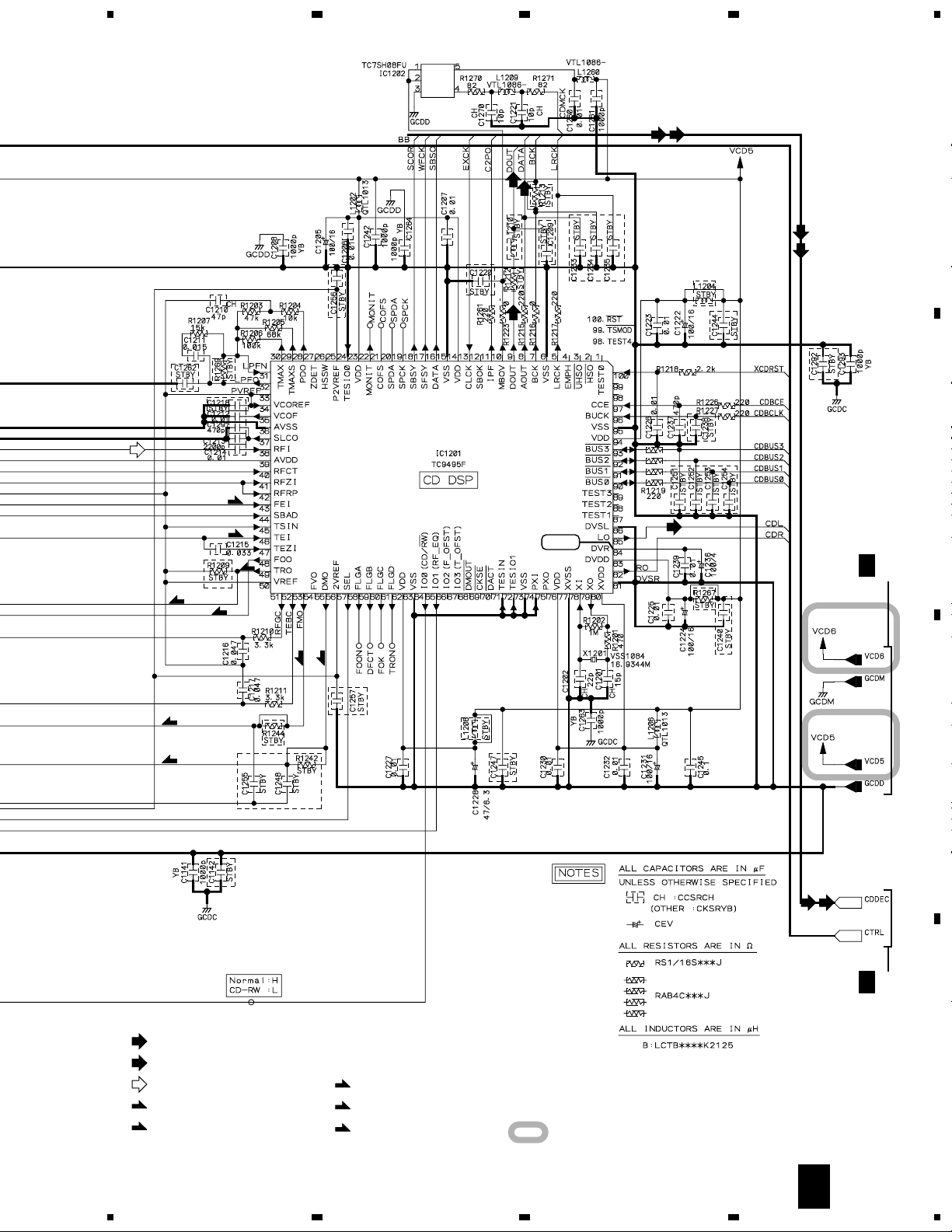
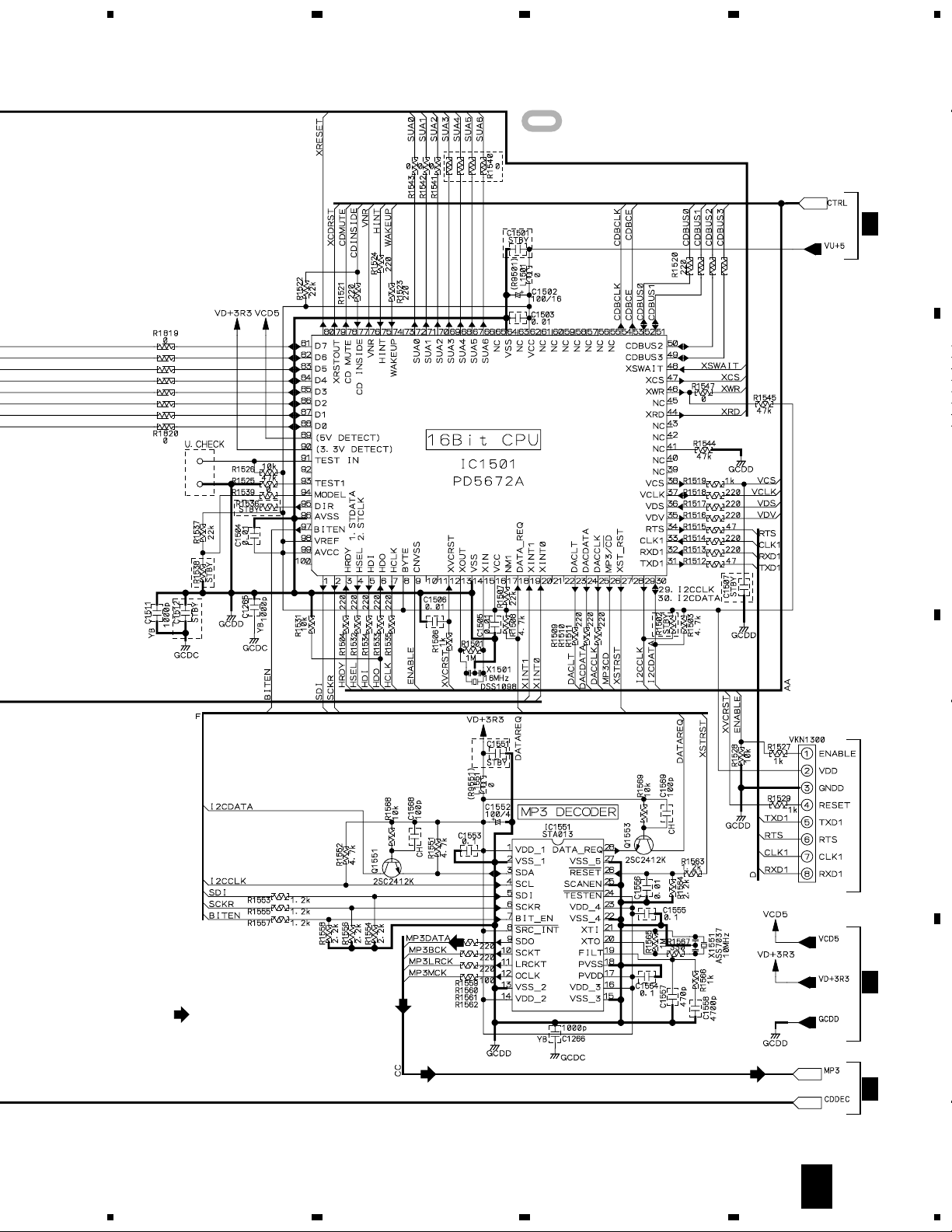
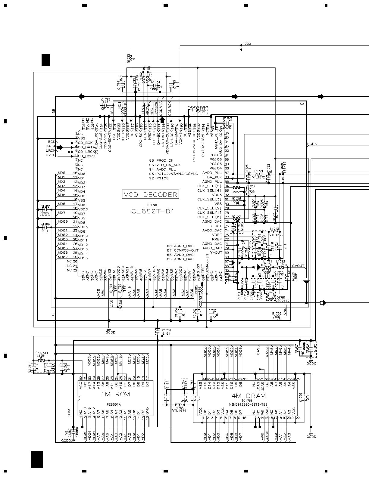
3.9 CD (3/3) ASSY
234
A
B
F 3/3
CD ASSY
(XWP3002)
(CD) (CD)
(CD)
(CD)
(CD)
C
D
28
3/3
F
1234
Page 29

(CD)
5
67
8
XC-IS22VCD
: The power supply is shown with the marked box.
A
SIGNAL ROUTE
(CD)
: CD AUDIO SIGNAL ROUTE
(D)
: DIGITAL SIGNAL ROUTE
: VIDEO SIGNAL ROUTE
(MP3)
: MP3 SIGNAL ROUTE
1/3, 2/3
F
3.35V
4.89V
B
(CD)
(CD)
CN1201
(D)
(CD)
C
CN5505
B
(CD)
(CD)
(D)
(CD)
(CD)
(MP3) (MP3) (MP3)
5
6
7
(D)
D
1/2, 2/3
(D)(D)
3/3
F
8
F
29
Page 30

1
XC-IS22VCD
3.10 F-TERMINAL ASSY
A
B
234
C
F-TERMINAL ASSY
H
D
30
H
1234
(XWZ3487)
Page 31

5
67
8
XC-IS22VCD
A
SIGNAL ROUTE
(L2)
: LINE 2 SIGNAL
(LO2)
: LINE OUT 2 SIGNAL
: The power supply is shown with the marked box.
B
NC
NC
(L2)
(L2)(L2)
(LO2)
C
(LO2)
CN103
CN49
I
5
C
CN3005
6
D
7
8
H
31
Page 32

1
234
XC-IS22VCD
3.11 FRONT PANEL, LIGHT-L, LIGHT-R, CD OPEN SW and CD CLOSE SW ASSYS
A
B
CN5504
CN52
B
CN50
J
LIGHT-R ASSY
(XWZ3414)
CN51
C
K
LIGHT-L ASSY
(XWZ3413)
D
32
I
J K
1234
Page 33

5
67
8
XC-IS22VCD
VCD/CD
: The power supply is shown with the marked box.
FRONT PANEL ASSY
I
(XWZ3408)
S5901: VCD/CD
S5902: TUNER
S5903: BASS
S5905: S5906: DISP
S5907: ENHANCE
S5908: TAPE
S5909: LINE 1, 2
S5910: TREBLE
S5911: FOLDER/TRACK
S5912: SET
S5913: +
S5914: TIMER/CLOCK ADJ
S5915: TAPE OPEN/CLOSE
S5916: PLAY/PAUSE
S5917: REC/STOP
S5918: ASES
S5919: ST.MEMORY/STOP
S5920: DOLBY NR ON/OFF
A
B
FOLDER/TRACK
J54
L
CD OPEN SW ASSY
(XWZ3411)
J55
M
CD CLOSE SW ASSY
(XWZ3412)
CN49
CN103
C
H
D
5
6
7
I
L M
8
33
Page 34

XC-IS22VCD
4. PCB CONNECTION DIAGRAM
NOTE FOR PCB DIAGRAMS :
1. Part numbers in PCB diagrams match those in the schematic
diagrams.
2. A comparison between the main parts of PCB and schematic
diagrams is shown below.
Symbol In PCB
Diagrams
BCE
BCE
D
Symbol In Schematic
Diagrams
BCEBCE
BCE
DGGSS
BCE
DGS
Part Name
Transistor
Transistor
with resistor
Field effect
transistor
Resistor array
3. The parts mounted on this PCB include all necessary parts for
several destinations.
For further information for respective destinations, be sure to
check with the schematic diagram.
4. View point of PCB diagrams.
Connector
Capacitor
SIDE A
P.C.Board
Chip Part
SIDE B
3-terminal
regulator
34
Page 35

1
4.1 TUNER MODULE
234
XC-IS22VCD
A
FM/AM TUNER MODULE
SIDE A
A
B
A
FM/AM TUNER MODULE
B
CN5503
Q202
(ANP7338-B)
SIDE B
C
D
Q201
1
2
IC201 Q205
3
Q203
IC202
(ANP7338-B)
Q204
A
4
35
Page 36

1
XC-IS22VCD
4.2 IF ASSY
23
SIDE A
4
A
B
IF ASSY
B
LCD ASSY
A
CN201
C
CN52
I
(XNP3038-B)
CN1201
F
D
36
B
1234
C
CN3004
E
J2202
C
CN3003
Page 37

B
1
IF ASSY
234
XC-IS22VCD
SIDE B
A
B
Q5504
Q5503
C
(XNP3038-B)
Q5505 IC5501
Q5506Q5501 Q5502
Q5751
Q5507 Q5752 IC5502
1
2
3
Q5508
B
4
D
37
Page 38

1
23
XC-IS22VCD
4.3 AF and MEDIA BLUE LED ASSYS
C
AF ASSY
A
TO. STEREO POWER AMP
(MAIN ASSY CN-3332)
B
4
CD TOUCH SENSOR
C
E
J2201
H
J103
(XNP3038-B)
D
SIDE A
IC131
Q2001
38
C
D
1234
IC3901 IC3004
IC3003
IC3002
B
CN5502
Q306 IC141
Q3004
IC301
Q304Q305Q4001
Q141Q131
IC3001
B
CN5501
D
MEDIA BLUE
LED ASSY
Page 39

1
234
XC-IS22VCD
C
AF ASSY
A
B
Q3005
IC7301
Q7301
1
Q3006
Q3011
IC3001
D
MEDIA BLUE
LED ASSY
IC3004 IC3901
IC3003
2
IC3002
Q3002Q3003
Q3001
Q4002
Q301
3
Q3010
Q3009Q3013
Q302
(XNP3038-B)
Q3015 Q3014
C
SIDE B
D
4
C
D
39
Page 40

1
XC-IS22VCD
4.4 DECK ASSY
A
E
DECK ASSY
CN3006
C
B
23
DECK MECHA
4
(XNP3039-C)
C
B
CN5506
Q2702
Q2704 Q2703
Q2701 Q2708
DECK MECHA
Q2805 Q2301
Q2801 Q2802 Q2803 Q2806 Q2802
DECK MECHADECK MECHA
VR2401VR2802VR2801VR2701 VR2402
VR2302
SIDE A
D
40
E
1234
Page 41

1
234
XC-IS22VCD
A
B
Q2305
IC2301 Q2303
Q2306 Q2304
Q2401
Q2402
Q2452
1
Q2351 Q2201 Q2252 Q2602 Q2603
Q2254 Q2253 Q2251 Q2262 Q2261 Q2263Q2451 IC2401 IC2201
IC2202
Q2707
SIDE B
2
3
Q2709 Q2705
IC2601
Q2710 Q2706Q2711
(XNP3039-C)
E
4
C
D
41
Page 42

1
XC-IS22VCD
4.5 CD and CD MOTOR ASSYS
SIDE A
A
F
CD ASSY
B
23
4
CD MECHANISM
ASSY
IC1751
IC1776
IC1771
C
PICK UP ASSY
(XNP3046-C)
D
42
F
G
1234
Page 43

1
234
XC-IS22VCD
G
CD MOTOR
ASSY
F
CD ASSY
SIDE B
A
Q1102
IC1201
IC1801
IC1202
IC1101
B
IC1851
Q1101
IC1301
Q1302
B
CN5505
(XNP3046-B)
Q1701
Q1551
IC1451
IC1401
Q1432
Q1434
Q1433
IC1701
IC1501
IC1756
C
IC1551
Q1431
IC1441
D
F
1
2
3
4
43
Page 44

1
XC-IS22VCD
4.6 FRONT TERMINAL, FRONT PANEL, LIGHT-L, LIGHT-R, CD CLOSE SW and
CD OPEN SW ASSYS
23
4
A
SIDE A
H
FRONT TERMINAL
ASSY
B
K
LIGHT-L ASSY
(XNP3038-B)
C
CN3005
(XNP3038-B)
M
CD CLOSE SW ASSY
I
FRONT PANEL ASSY
(XNP3038-B)
L
CD OPEN SW ASSY
(XNP3038-B)
C
B
CN5504
D
(XNP3038-B)
J
LIGHT-R ASSY
44
H
I
1234
J
K
L
M
Page 45

1
234
XC-IS22VCD
I
FRONT PANEL ASSY
(XNP3038-B)
K
LIGHT-L ASSY
(XNP3038-B)
H
A
SIDE B
FRONT TERMINAL
ASSY
B
C
Q5902
Q5901
Q5905
Q5904
Q5903
(XNP3038-B)
(XNP3038-B)
D
J
LIGHT-R ASSY
H
1
2
3
I
J
K
45
4
Page 46

XC-IS22VCD
5. PCB PARTS LIST
NOTES:•Parts marked by "NSP" are generally unavailable because they are not in our Master Spare Parts List.
The mark found on some component parts indicates the importance of the safety factor of the part.
•
Therefore, when replacing, be sure to use parts of identical designation.
When ordering resistors, first convert resistance values into code form as shown in the following examples.
•
Ex.1 When there are 2 effective digits (any digit apart from 0), such as 560 ohm and 47k ohm (tolerance is shown by J=5%,
and K=10%).
560 Ω→56 × 10
47k Ω→47 × 103→ 473 ........................................................ RD1/4PU 4 7 3 J
0.5 Ω→R50 .....................................................................................RN2H
1 Ω→1R0 .....................................................................................RS1P
Ex.2 When there are 3 effective digits (such as in high precision metal film resistors).
5.62k Ω→ 562 × 10
1
→ 561 ........................................................ RD1/4PU 5 6 1 J
R 5 0
1 R 0
1
→ 5621 ...................................................... RN1/4PC 5 6 2 1 F
K
K
Mark No. Description Part No.
LIST OF ASSEMBLIES
FM/AM TUNER MODULE AXQ7228
NSP MEDIA ASSY XWM3182
NSP AF ASSY XWZ3464
NSP IF ASSY XWZ3465
NSP FRONT PANEL ASSY XWZ3408
NSP F-TERMINAL ASSY XWZ3487
NSP CD MOTOR ASSY XWZ3410
NSP CD OPEN SW ASSY XWZ3411
NSP CD CLOSE SW ASSY XWZ3412
NSP LIGHT- L ASSY XWZ3413
NSP LIGHT- R ASSY XWZ3414
NSP MEDIA BLUE LED ASSY XWZ3415
NSP DECK ASSY XWX3038
SEMICONDUCTORS
COILS AND FILTERS
CD ASSY XWP3002
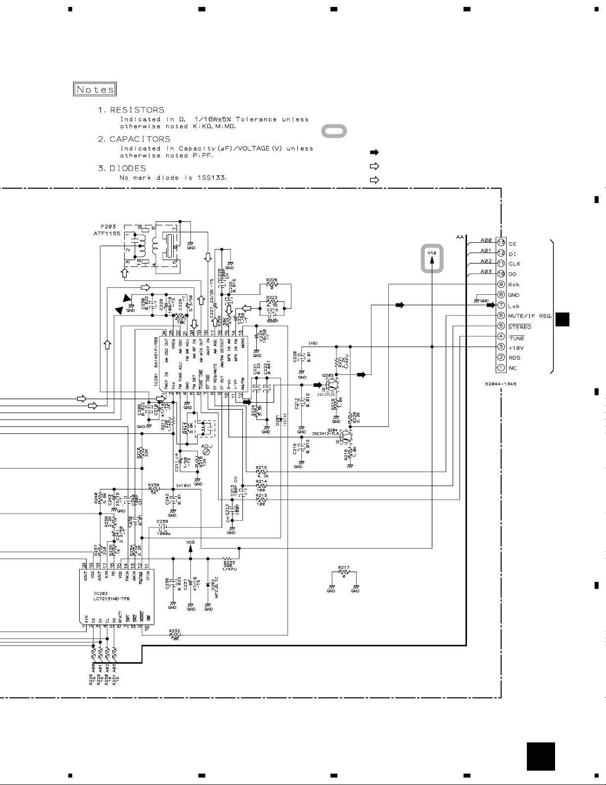
FM/AM TUNER MODULE
A
IC201 BA1451F
IC202 LC72131MD-TFB
Q 201, Q 204, Q 205 2SC2412K
Q 202 DTA124ES
Q 203 DTC124EK
D 201 1SS133
D 202 MTZJ5.1C
L 201 ATE7003
F 202 ATF-107
F 201 ATF-119
F 203 ATF1155
Mark No. Description Part No.
C 229 CEAT101M10
C 224 CEAT1R0M50
C 227 CEAT220M25
C 241 CEAT2R2M50
C 243 CEAT330M16
C 228 CEAT3R3M50
C 237 CEAT470M10
C 211 CEJA1R0M50
C 210 CEJA470M16
C 204, C 238, C 602 CKSRYB102K50
C 101, C 102, C 208, C 220, C 239 CKSRYB103K50
C 242, C 601 CKSRYB103K50
C 216, C 217 CKSRYB123K50
C 225 CKSRYB153K50
C 201, C 205, C 209, C 214, C 230 CKSRYB223K50
C 236, C 603 CKSRYB223K50
C 221 CKSRYB224K10
C 202, C 222 CKSRYB473K16
C 215 CKSRYB681K50
RESISTORS
R 211 RD1/4PU221J
R 221 RD1/4PU222J
R 233 RD1/4PU391J
R 243 RS1/10S0R0J
R 103 RS1/10S331J
R 104 RS1/10S391J
Other Resistors RS1/16S&&& J
OTHERS
CN201 (13P FFC CONNECTOR) 52044-1345
BN201 (4P TERMINAL) AKA7003
0 (SHIELD CASE T (Mtl) ANK7072
0 (SHIELD CASE B (Mtl) ANK7073
X 201 (F= 7.2000 MHz) ASS1093
CAPACITORS
C 206 CCSRCH100D50
C 212, C 213, C 226, C 233–C 235 CCSRCH101J50
C 240 CCSRCH101J50
C 231, C 232 CCSRCH150J50
C 223 CEAT100M50
46
Page 47

XC-IS22VCD
Mark No. Description Part No. Mark No. Description Part No.
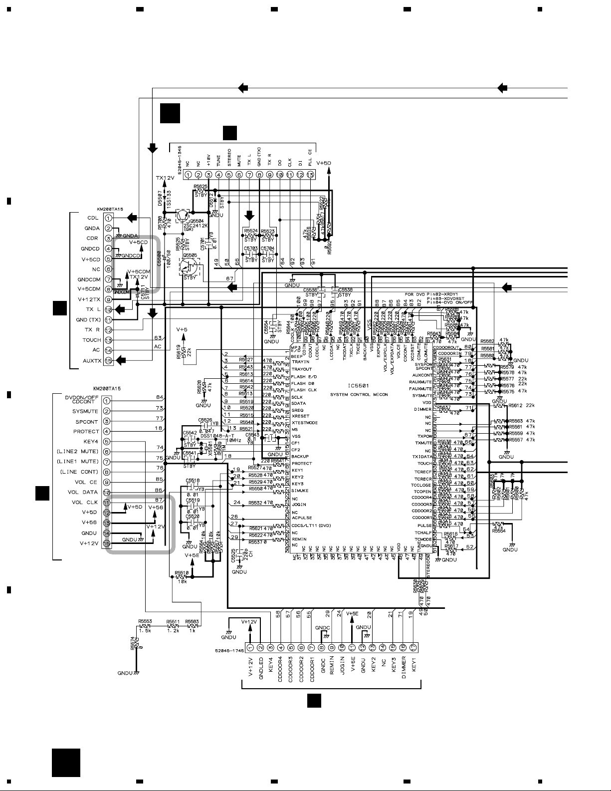
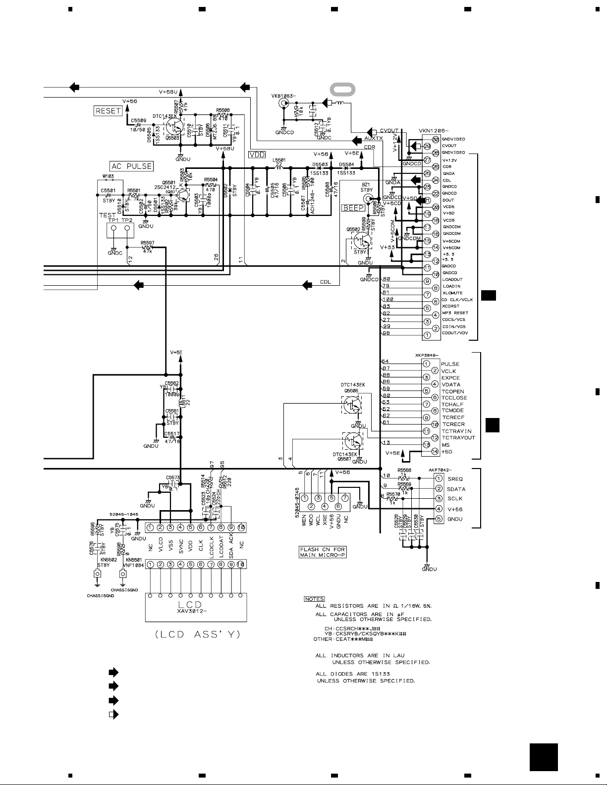
IF ASSY
B
SEMICONDUCTORS
IC5501 PDC075B
Q5501, Q5504 2SC2412K
Q5503, Q5506, Q5507 DTC143EK
D5501, D5503-D5505, D5507 1SS133
D5506 MTZJ6.8B
COILS AND FILTERS
L5501, L5511 LAU220J
L5652 VTL1084
CAPACITORS
C5507 (0.047F/5.5V) ACH1246
C5523 CCSRCH100D50
C5577 CCSRCH101J50
C5524 CCSRCH220J50
C5525 CCSRCH221J50
C5509 CEAT100M50
C5500 CEAT101M50
C5502 CEAT1R0M50
C5505, C5508, C5517 CEAT470M16
C5503, C5562 CKSRYB102K50
C5518-C5520, C5701 CKSRYB103K50
C5504, C5506, C5511, C5512, C5543 CKSRYB104K25
C5573, C5575 CKSRYB104K25
C5526 CKSRYB473K50
RESISTORS
Other Resistors RS1/16S&&& J
OTHERS
CN5511 (7P FFC CONNECTOR) 52045-0745
CN5509 (10P FFC CONNECTOR) 52045-1045
CN5503 (13P FFC CONNECTOR) 52045-1345
CN5504 (17P FFC CONNECTOR) 52045-1745
CN5507 (5P SOCKET) AKP7042
X 5501 (F= 10MHz) DSS1048
CN5501,CN5502 (15P PLUG) KM200TA15
0 (PCB BINDER) VEF1040
JA5001 (1P JACK) VKB1063
CN5505 (30P CONNECTOR) VKN1206
Q3014 DTC124EK
D3006 1SS133
D141, D3011, D3013, D3016, D302 1SS355
D3049, D7301-D7304 1SS355
D3004 MTZJ10C
D304 S5688G
COILS AND FILTERS
L7301 LAU220J
CAPACITORS
C3057-C3059 CCSRCH101J50
C7102, C7104, C7301 CCSRCH221J50
C3205, C3206 CCSRCH271J50
C3903 CCSRCH471J50
C3902 CCSRCH681J50
C134, C3011-C3013, C3025, C3026 CEAT100M50
C3029, C3043, C3904, C3905, C4004 CEAT100M50
C4006 CEAT101M16
C131, C141, C3023, C3024, C3901 CEAT1R0M50
C301 CEAT220M50
C3001-C3010, C3014, C3016, C3027 CEAT2R2M50
C3055, C3056 CEAT2R2M50
C133, C143, C3033, C3096, C7302 CEAT470M16
C7307 CEAT4R7M50
C3041, C3042 CEATR47M50
C3910, C7131 CKSRYB103K50
C132, C142, C3015, C3019-C3022 CKSRYB104K25
C3034-C3036, C3039, C3040, C3044 CKSRYB104K25
C3047-C3049, C3051, C3052, C3099 CKSRYB104K25
C3111, C7305, C7306, C901 CKSRYB104K25
C3065 CKSRYB222K50
C305, C3121-C3123 CKSRYB223K50
C3906 CKSRYB473K50
C3053 CKSRYB474K10
C3017, C3018 CKSRYB822K50
RESISTORS
R2002 RD1/4PU100J
R3205 RD1/4PU223J
VR3901 (10KΩ- B) XCS3006
Other Resistors RS1/16S&&& J
KN5501 (EARTH METAL FITTING) VNF1084
CN5506 (14P PLUG) XKP3049
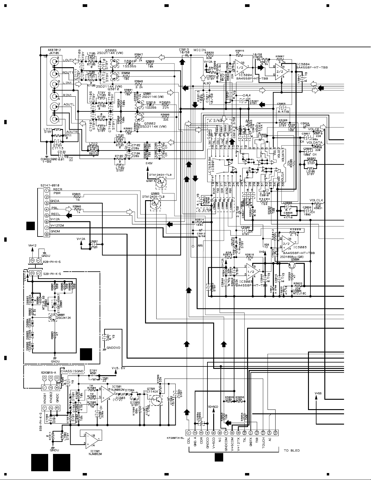
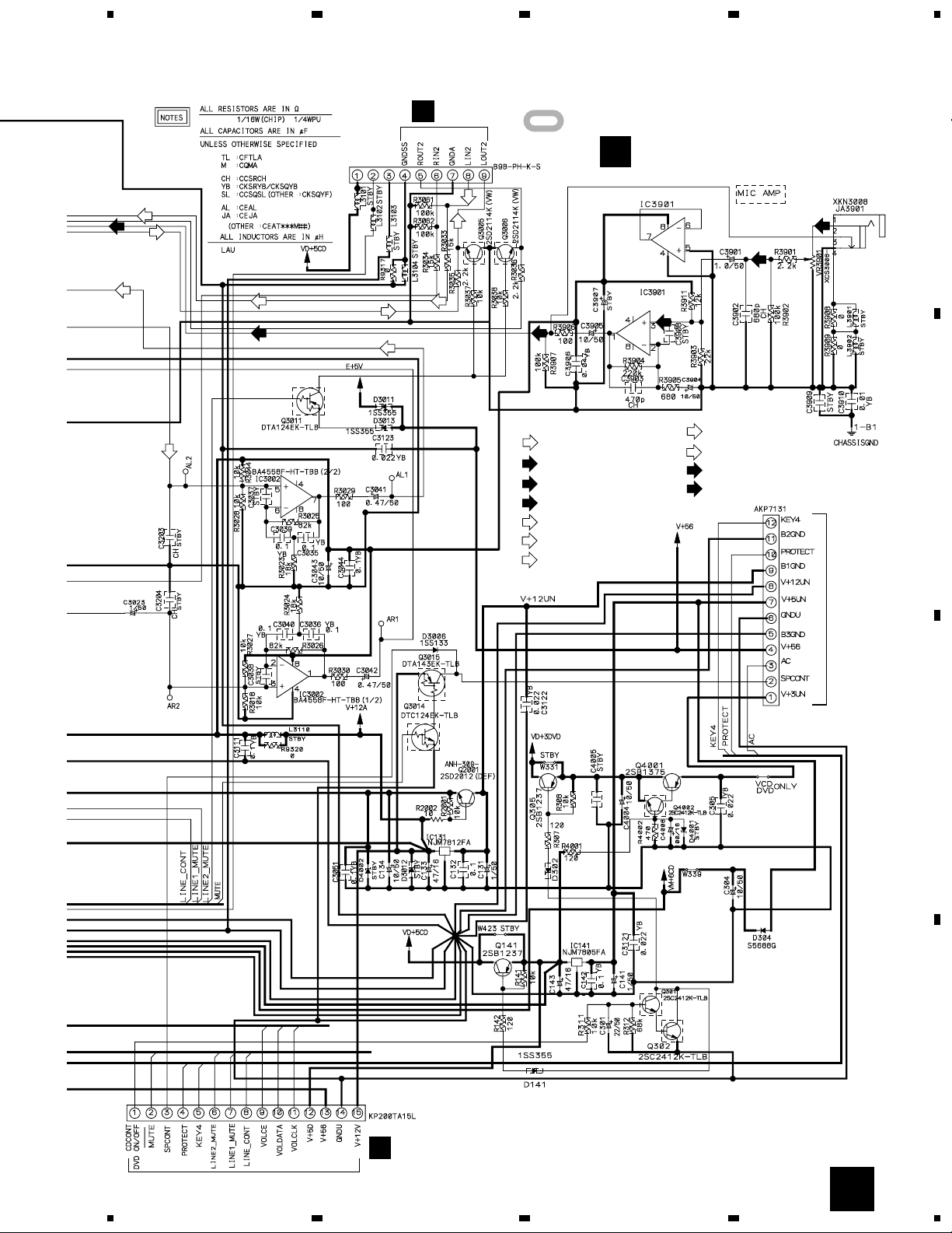
AF ASSY
C
SEMICONDUCTORS
IC3002-IC3004, IC3901 BA4558F-HT
IC3001 LC75343M
IC7301 NJM062M
IC141 NJM7805FA
IC131 NJM7812FA
Q141, Q305 2SB1237X
Q4001 2SB1375
Q301, Q302, Q4002 2SC2412K
Q3004 2SD1858X
Q2001 2SD2012
Q3001, Q3002, Q3005, Q3006 2SD2114K
Q3009, Q3010 2SD2114K
Q3003, Q3011, Q3013 DTA124EK
Q3015 DTA143EK
Q7301 DTC114EK
OTHERS
CN3006 (8P JUMPER CONNECTOR) 52147-0810
7105 (6P PIN JACK) AKB7012
CN3001 (12P CONNECTOR) AKP7131
CN3008 (2P CONNECTOR) B2B-PH-K
CN101 (3P CONNECTOR) B3B-PH-K
CN3005 (9P CONNECTOR) B9B-PH-K
CN3003, CN3004 (15P SOCKET) KP200TA15L
0 (PCB BINDER) VEF1040
JA3901 (MINI JACK) XKN3008
47
Page 48

XC-IS22VCD
Mark No. Description Part No. Mark No. Description Part No.
C 2221,C 2222,C 2261,C 2262 CEAT4R7M50
MEDIA BLUE LED ASSY
D
SEMICONDUCTORS
Q 8001 2SC2412K
D 8003-D 8006 1SS355
D 8001 E1S02-4B0A7
D 8002 MTZJ5.6B
RESISTORS
Other Resistors RS1/16S&&& J
OTHERS
CN8001 (2P CONNECTOR) S2B-PH-K
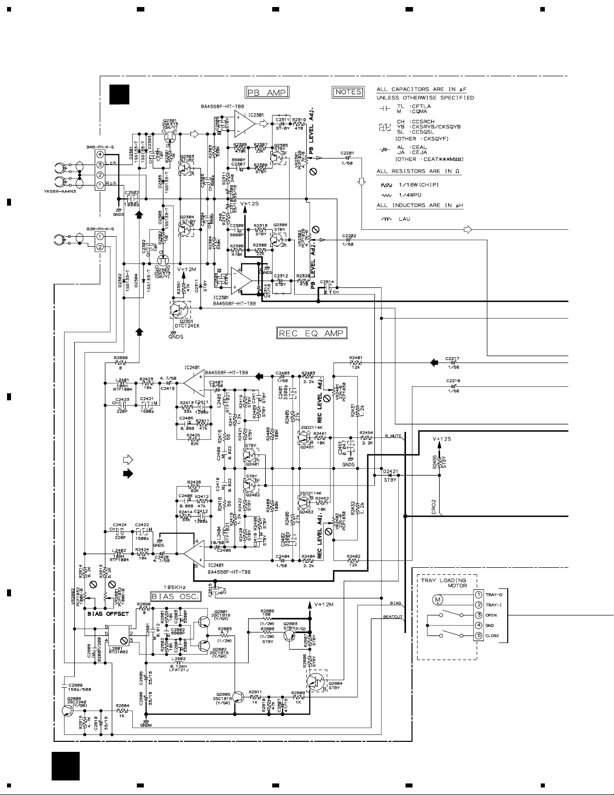
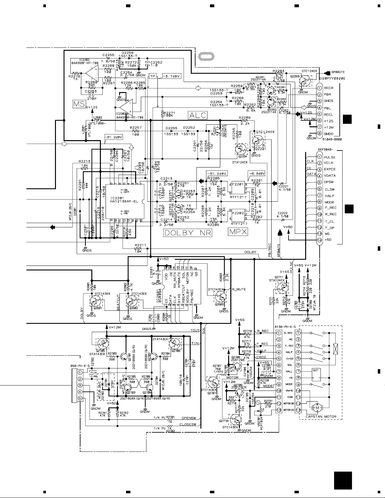
DECK ASSY
E
SEMICONDUCTORS
IC2202,IC2301,IC2401 BA4558F-HT
IC2601 BU4094BCF
IC2201 HA12136AF
Q 2709 2SB1197K
Q 2708 2SB1296
Q 2801,Q 2802,Q 2805 2SC1815
Q 2806 2SC2240
Q 2253 2SC2412K
Q 2701-Q 2704 2SD1858X
Q 2251,Q 2252,Q 2261,Q 2262 2SD2114K
Q 2451,Q 2452 2SD2114K
Q 2301,Q 2302 2SK373
Q 2254,Q 2711 DTA124EK
Q 2705,Q 2706 DTA143EK
Q 2201,Q 2263,Q 2351 DTC124EK
Q 2601-Q 2603,Q 2707,Q 2710 DTC143EK
D 2252-D 2256,D 2301-D 2306 1SS133
D 2705,D 2706 1SS133
D 2709 MTZJ4.7B/C
D 2201,D 2703,D 2704 MTZJ6.2B/C
COILS AND FILTERS
L 2802 LFA121J
L 2801 RTD1082
L 2401,L 2402 RTF1004
L 2403,L 2404 RTF1021
F 2201,F 2202 RTF1217
L 2501,L 2502 VTL1096
CAPACITORS
C 2809 CCCSL151K2H
C 2301,C 2302 CCSRCH100D50
C 2423,C 2424,C 2602 CCSRCH221J50
C 2253 CCSRCH271J50
C 2303,C 2304 CCSRCH681J50
C 2203,C 2204,C 2207,C 2215 CEAT100M50
C 2407,C 2408 CEAT100M50
C 2701 CEAT101M16
C 2201,C 2202,C 2217,C 2218,C 2255 CEAT1R0M50
C 2403,C 2404 CEAT1R0M50
C 2251 CEAT220M50
C 2216 CEAT221M10
C 2213,C 2214,C 2254 CEAT2R2M50
C 2309,C 2310,C 2805,C 2806,C 2810 CEAT330M16
C 2314,C 2807 CEAT470M16
RESISTORS
OTHERS
CD ASSY
SEMICONDUCTORS
C 2419,C 2420 CEAT4R7M50
C 2205,C 2206 CEATR22M50
C 2252 CKSQYB105K10
C 2702 CKSQYB474K16
C 2501,C 2502 CKSRYB102K50
C 2601 CKSRYB104K25
C 2411,C 2412 CKSRYB122K50
C 2211,C 2212,C 2421,C 2422 CKSRYB152K50
C 2401,C 2402 CKSRYB332K50
C 2451 CKSRYB473K50
C 2808 CQHA822J2A
C 2209,C 2210 CQMA103J50
C 2801 CQMA123J50
C 2409,C 2410 CQMA223J50
C 2803,C 2804 CQMA332J50
C 2307,C 2308,C 2802 CQMA682J50
C 2405,C 2406 CQMBA683J50
R 2805 RD1/2PM161J
R 2703-R 2706 RD1/2PM391J
R 2803 RD1/2PM4R7J
R 2701,R 2702 RD1/4PU102J
R 2707 RD1/4PU751J
VR2701 (1kΩ) PCP1024
VR2301,VR2302 (4.7kΩ) PCP1028
VR2401,VR2402 (22kΩ) PCP1030
VR2801,VR2802 (100kΩ) PCP1032
Other Resistors RS1/16S&&& J
102 (8P CABLE HOLDER) 51048-0800
CN2701 (13P CONNECTOR) B13B-PH-K
CN2302 (2P CONNECTOR) B2B-PH-K
CN2301 (4P CONNECTOR) B4B-PH-K
CN2603 (5P CONNECTOR) B5B-PH-K
J2201 (8P FLAT CABLE) D20PYY0825E
0, 1 (PCB BINDER ) VEF1040
CN2202 (14P CONNECTOR) XKP3048
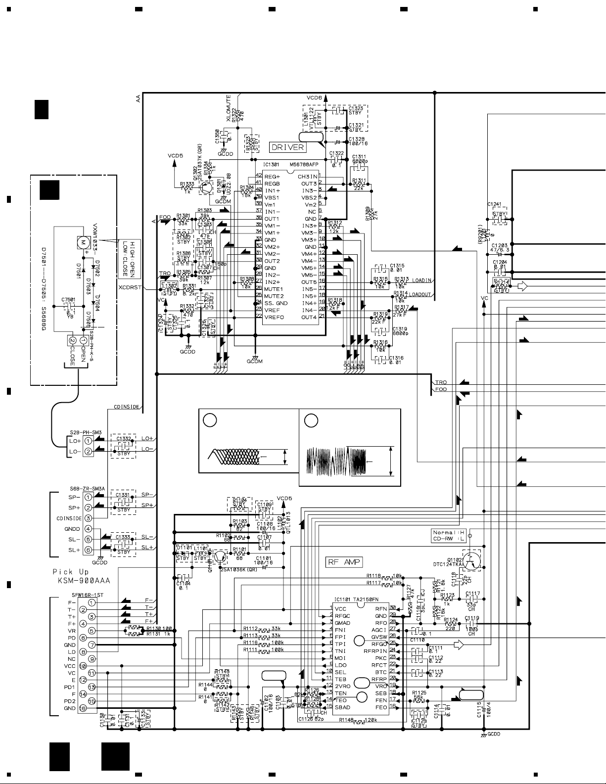
F
IC1701 CL680T-D1
IC1851 LC324265BT-25P
IC1801 LC895199K-ND2
IC1301 M56788AFP
IC1756 MSM514260C-60TS
IC1401 PCM1742KE
IC1501 PD5672B
IC1751 PEB001A
IC1551 STA013
IC1101 TA2150FN
IC1451 TC74HCT157AF
IC1202 TC7SH08FU
IC1776 TC7W14FU
IC1771 TC7WU04FU
IC1201 TC9495F
Q1101 2SA1036K
Q1302 2SA1037K
Q1551, Q1553, Q1701 2SC2412K
Q1433, Q1434 2SD2114K
Q1431, Q1432 DTA124EK
48
Page 49

XC-IS22VCD
Mark No. Description Part No. Mark No. Description Part No.
Q1102 DTC124TKA
D1431, D1432 DAN202K
D1301 UDZ2.0B
COILS ANDFILTERS
L1712 LCTB1R8K2125
L1711 LCTB2R7K2125
L1102, L1202, L1206 QTL1013
L1713, L1721 VTL1072
L1756 VTL1074
L1209, L1260, L1777 VTL1086
L1771, L1776 VTL1087
CAPACITORS
C1221, C1270 CCSRCH100D50
C1119, C1568, C1569, C1712, C1734 CCSRCH101J50
C1773, C1774 CCSRCH120J50
C1201 CCSRCH150J50
C1307, C1714 CCSRCH151J50
C1118, C1202 CCSRCH220J50
C1711 CCSRCH221J50
C1117 CCSRCH330J50
C1713 CCSRCH331J50
C1210, C1303, C1720, C1735, C1737 CCSRCH470J50
C1126 CCSRCH820J50
C1116 CCSRCJ3R0C50
C1401, C1402, C1405, C1417, C1418 CEV100M16
C1001, C1008, C1101, C1102, C1108 CEV101M16
C1205, C1222, C1224, C1231, C1328 CEV101M16
RESISTORS
R1540, R1819, R1820 RAB4C0R0J
R1219, R1520 RAB4C221J
R1546, R1813-R1816 RAB4C473J
R1318 RS1/16S1202F
R1319 RS1/16S2202F
R1317 RS1/16S2702F
Other Resistors RS1/16S&&& J
OTHERS
X1551 (F=10.00MHz) ASS7037
X1501 (F=10 MHz) DSS1098
X1201 (F= 16.93MHz) VSS1084
X1751 (F= 27.00MHz) VSS1086
X1801 (F=33.86MHz) VSS1130
CN1302 (2P CONNECTOR) B2B-PH-SM3
CN1201 (30P CONNECTOR) RKN1039
CN1301 (6P CONNECTOR)
CN1101 (16P FFC CONNECTOR) SFW16R-1ST-TFB
CN1501 (8P CONNECTOR) VKN1300
CD MOTOR ASSY
G
SEMICONDUCTORS
D 7506 11EQS04
D 7501-D 7505 S5688G
CAPACITORS
C 7501 CKSRYB104K25
S6B-ZR-SM3A-TFB
C1502 CEV101M16
C1002, C1115, C1236, C1552 CEV101M4
C1203, C1228 CEV470M6R3
C1141, C1208, C1242, C1261 CKSRYB102K50
C1263-C1268, C1293, C1511, C1762 CKSRYB102K50
C1771, C1776, C1824, C1825 CKSRYB102K50
C1103, C1107, C1114, C1130, C1204 CKSRYB103K50
C1206, C1207, C1212, C1214, C1223 CKSRYB103K50
C1225-C1227, C1230, C1232, C1239 CKSRYB103K50
C1260, C1315, C1316, C1406 CKSRYB103K50
C1503-C1506, C1556, C1756, C1761 CKSRYB103K50
C1813 CKSRYB103K50
C1104, C1110, C1111, C1131, C1245 CKSRYB104K16
C1322, C1325, C1350, C1403, C1404 CKSRYB104K16
C1451, C1553-C1555, C1703-C1706 CKSRYB104K16
C1716, C1717, C1721-C1723, C1733 CKSRYB104K16
C1736, C1753, C1758, C1759, C1772 CKSRYB104K16
C1777, C1803-C1807, C1812 CKSRYB104K16
C1852, C1853 CKSRYB104K16
C1725 CKSRYB152K50
C1211 CKSRYB153K25
C1213, C1519, C1520 CKSRYB222K50
C1112, C1113 CKSRYB224K10
C1215 CKSRYB333K16
C1237, C1291, C1557 CKSRYB471K50
C1558 CKSRYB472K50
C1216, C1217 CKSRYB473K16
C1311, C1319 CKSRYB682K50
OTHERS
CN11 (2P CONNECTOR) S2B-PH-K
F-TERMINAL ASSY
H
SEMICONDUCTORS
D7211, D7212 1SS355
COILS AND FILTERS
L7202, L7203, L7211, L7212 VTL1105
L7221, L7222 VTL1105
CAPACITORS
C5902 CEAT101M10
C7213, C7214 CKSRYB102K50
C5903 CKSRYB103K50
C7231 CKSRYB472K50
RESISTORS
Other Resistors RS1/16S&&& J
OTHERS
7304 (MINI JACK) AKN-210
7303 (MINI JACK) AKN7003
5901 (REMOTE RECEIVER UNIT) GP1U28Y
49
Page 50

XC-IS22VCD
Mark No. Description Part No.
FRONT PANEL ASSY
I
SEMICONDUCTORS
Q 5901,Q 5903-Q 5905 2SC2412K
Q 5902 DTA124EK
D 5902-D 5905 1SS133
SWITCHES
S 5901-S 5920 ASG7013
S 5921 ASX7026
RESISTORS
R 5934 RD1/4PU101J
Other Resistors RS1/16S&&& J
OTHERS
54,55 (3P CABLE HOLDER) 51048-0300
CN52 (17P CONNECTOR) 52044-1745
CN50, CN51(3PJUMPER CONNECTOR)52151-0310
J 54, J 55(JUMPER WIRE) D20PYY0325E
CN49 (3P CONNECTOR) S3B-PH-K
LIGHT- R ASSY
J
SEMICONDUCTORS
D 5908 NSPWF50BS-9706
CAPACITORS
C 5907 CKSRYB103K50
OTHERS
53 (3P CABLE HOLDER ) 51048-0300
J 51 (JUMPER WIRE9 D20PYY0310E
LIGHT- L ASSY
K
SEMICONDUCTORS
9706
CAPACITORS
OTHERS
CD OPEN SW ASSY
SWITCHES
D 5906 NSPWF50BS-
C 5906 CKSRYB103K50
52 (3P CABLE HOLDER) 51048-0300
J 50 (JUMPER WIRE) D20PYY0310E
L
S 7401,S 7402 VSH1019
OTHERS
57 (CABLE HOLDER) 51048-0300
CD CLOSE SW ASSY
M
SWITCHES
S 7403,S 7404 ASG7015
OTHERS
56 (CABLE HOLDER) 51048-0300
50
Page 51

6. ADJUSTMENT
For adjustment, use the stereo power amplifier (M-IS21).
6.1 DECK SECTION
6.1.1 Adjustment Condition
(1) The ground at the time of adjustment shall be W166.
(Refer to Fig. 6–3).
(2) Clean the heads and demagnetize them using a head eraser.
(3) Set the measurement level to 0 dBV = 1 Vrms.
(4) Use the specified tape for adjustment. Use the labeled (A) side
of the test tape.
NCT–111 : For Tape Speed adjustment
STD-331E : For Playback adjustment
STD–632 : Normal blank tape
* As the reference recording level is 250 nwb/m for STD–
331E, the recording level will be higher than 4 dB for STD–
331B (160nwb/m). When adjusting, pay carefully attention
to the type of tape used.
(5) Provide yourself with the following measuring devides:
÷ AC millivoltmeter
÷ Low-frequency oscillator
÷ Attenuator
÷ Oscilloscope
(6) Adjust both right and left channels unless other wise specified.
(7) Turn the DOLBY NR switch off unless otherwize specified.
(8) Warm up the unit for several minutes before adjustment. In
particular, be sure to warm up the unit in the REC/PLAY mode
for 3 to 5 minutes before starting recording/playback frequency
characteristics adjustment.
(9) Always follow the indicated adjustment order.
Otherwise, a complete adjustment may not be achieved.
7 List of Adjustments
¶ Playback Section
(1) Tape Speed Confirmation
(2) Head Azimuth Adjustment
(3) Playback Level Adjustment
¶ Recording Section
(1) Recording Bias Adjustment
(2) Recording Level Adjustment
PLAY BACK
250
3dB
RECORDING
250
3dB
XC-IS22VCD
12.5k
10k
3dB 4dB
12.5k
10k
5dB
3dB
0 dB
30s
315 Hz
Fig. 6-1 Frequency Characteristics
Dolby noise reduction manufactured under license from Dolby
Laboratories Licensing Corporation.
“DOLBY” and the double-D symbol are trademarks of Dolby
Laboratories Licensing Corporation.
0 dB: 315 Hz, 250 nwb/m
30 s 30 s 30 s 10s 10s .......................................................................................................... 10s
6.3 kHz 10 kHz 315 Hz 14 kHz
12.5
kHz
10 kHz
6.3
8 kHz 4 kHz2 kHz
kHz
1 kHz
500Hz250Hz125
Hz
Fig. 6-2 Test Tape STD– 331E
63 Hz 40 Hz
–20 dB
51
Page 52

XC-IS22VCD
6.1.2 Playback Section
(1) Tape Speed Confirmation
No. Mode Input Signal/Test Tape Adjustment Points Measurement Points Adjustment Value Remarks
PLAY1
NCT-111 (3 kHz)
VR2701 (DECK ASSY)
(Refer to Fig. 6-3)
TP R (C2204)
(DECK ASSY)
(2) Head Azimuth Adjustment
¶ This unit is equipped with auto tape selector.
¶ Do not switch between forward and reverse operation with the screwdriver inserted.
No. Mode Input Signal/Test Tape Adjustment Points
Measurement
Points
3000 Hz Hz
Adjustment
Value
+10
–10
FWD adjustment
REV Confirmation
( 3000 Hz Hz )
Remarks
+60
–60
PLAY1
STD-331E test tape
(Playback: 10 kHz, –20 dB)
Head azimuth
adjustment Screw
(Refer to Fig. 6-3)
TP L (C2203)
TP R (C2204)
(DECK ASSY)
Max. Playback
signal level
(3) Playback Level Adjustment
¶ Since this adjustment determines playback DolbyNR level, Perform it carefully.
Measurement
Points
1
PLAY
STD-331E test tape
(Playback: 315 Hz, 0 dB)
L ch
R ch VR2302
VR2301
TP L (C2203)
TP R (C2204)
(DECK ASSY)
Adjustment
Value
–3.7 dBV
6.1.3 Recording Section
(1) Recording Bias Adjustment
¶ After the adjustment, caution should be exercised so as not to become under bias by checking the distortion rate.
No. Mode Input Signal/Test Tape Adjustment Points
REC/
1
PAUSE
REC =
2
PLAY
Input a 315Hz signal to the LINE -
IN terminal. ∗
Load the STD–632 test tape and
record/playback the 315Hz and
10kHz signals. (see the Note below)
Input signal level –23.7 dBV
L ch
R ch VR2802
VR2801
Measurement
Points
TP L (C2203)
TP R (C2204)
(DECK ASSY)
Adjustment
Value
Repeat adjustment until playback level of
the 10kHz signal is within 0.5dBV ±0.5dB
from that of the 315Hz signal.
After adjustment, apply silicon
bond to the head azimuth
adjustment screw.
RemarksNo. Mode Input Signal/Test Tape Adjustment Points
Remarks
Note: Set the 10kHz input signal level to the same value as the 315Hz input signal level of step 1.
(2) Recording Level Adjustment
No. Mode Input Signal/Test Tape Adjustment Points
REC/
1
PAUSE
REC =
2
PLAY
Input a 315Hz signal to the LINE-
IN terminal.∗
STD–632 test tape and record/
playback the 315Hz signal.
Input signal level –7.7 dBV
L ch
R ch VR2402
VR2401
52
Measurement
Points
TP L (C2203)
TP R (C2204)
(DECK ASSY)
Adjustment
Value
Repeat recording, playback and
adjustment until playback level of the
315Hz signal becomes –
Remarks
7.7dBV±0.5dB
.
Page 53

XC-IS22VCD
DECK ASSY
E
SIDE A
W166
(TP GND)
C2203
(TP Lch)
VR2301
(Lch)
PB LEVEL
C2204
(TP Rch)
VR2302
(Rch)
VR2701
MECHANISM UNIT
VR2801
(Lch)
FWD Azimuth
Adjustment Screw
BIAS TAPE SPEED
VR2802
(Rch)
REV Azimuth
Adjustment Screw
VR2401
(Lch)
REC LEVEL
VR2402
(Rch)
Fig. 6-3 Adjustment and Measurement Points
53
Page 54

XC-IS22VCD
6.2 CD SECTION
Note : There is no information to be shown in this CD adjustment.
6.2.1 HOW TO START / CANCEL TEST MODE
TEST MODE : ON
B
IF ASSY
W323
W324
TEST MODE
Short circuit
IF ASSY
W323
W324
IF ASSY
SIDE A
Release
CD
TX TEST
TEST 2
Note:
When cannot enter the test mode,
set to the DEMO ON.
Setting method: Press the DOLBY
NR ON/OFF (DEMO) key more
than three seconds during
STAND BY .
TEST MODE
Short point
W323
W324
TEST MODE : STOP → CANCEL
STOP
STOP
All Operations
54
Rear
Fig. 6-4
Page 55

FUNCTION OF CD TEST MODE
DISPLAY
Laser diode: LIGHT UP
Focus servo: ON
–
G
N
I
N
U
T
·
4
·
1
Carriage IN
S
T
.
M
E
M
O
R
Y
·
S
T
O
P
7
STOP
STEREO CD/VCD TUNER DECK
XC-IS22VCD
CD
ENHANCE
BASS
TUNER
DOLBY NR
ON/OFF(DEMO)
DO
LBY
B NR
P
S
I
D
E
D
O
1
M
E
S
R
E
S
V
T
.
E
M
R
E
M
O
R
A
S
E
FRONTLOADINGTRAY
L
IN
E
2
·
Y
S
4
·
IN
OPEN/
T
·
S
T
O
O
V
–
2
G
N
I
N
U
P
7
CLOSE
.
/
J
L
O
G
+
3
–
+
T
U
N
I
N
6
MECHANISMDECK
DIGITAL OUT LINE2 OUT
XC-IS22VCD
OPEN/CLOSE TOUCH SENSOR
CD cover
Open / Close
+
T
U
N
I
N
G
·
¢
S
TAPE
E
T
FOLDER/TRACK
G
·
¢
T
I
M
·
E
¡
R
/
C
L
O
C
K
A
D
E
J
S
U
A
P
/
Y
TREBLE
A
L
P
LINE1.2
P
O
T
S
/
C
E
R
0
E
P
A
T
E
S
O
L
/C
N
E
P
O
Carriage OUT
Spindle kick,
Tracking servo,
Slider servo: ON/OFF
·
¡
E
S
U
A
P
/
Y
A
L
P
6
TEST MODE : PLAY
TEST DISC: YEDS-7
STEREO CD/VCD TUNER DECK
XC-IS22VCD
OPEN/ CLOSE
DISPLAY
Laser diode: LIGHT UP
Focus servo: CLOSE
LCD DISPLAY
LCD DISPLAY
[FOCUS ON]
[ : ]
A
TEST MODE : STOP CANCEL
S
T
.
M
E
M
O
R
Y
·
S
T
O
P
7
E
S
U
A
P
/
Y
A
L
P
6
CLOSE
Tracking servo:
LCD DISPLAY
[SERVO ON]
E
S
U
A
P
/
Y
A
L
P
6
Spindle motor: START
Spindle servo: CLOSE
Auto-matic adjustment
Average proccesing
LCD DISPLAY
[SPNDL KICK] → [SERVO ON]
E
S
U
A
P
/
Y
A
L
P
6
OPEN
LCD DISPLAY
[SERVO OFF]
A
–
+
T
G
U
N
I
N
N
I
U
T
·
4
·
1
inwards
Pickup Move
LCD DISPLAY
[XX : XX] → [SERVO OFF]
N
G
·
¢
·
¡
outwards
STOP all operation
55
Page 56

XC-IS22VCD
6.3 TUNER SECTION
6.3.1 AM TUNER SECTION
There is no adjustment in the AM tuner.
6.3.2 FM TUNER SECTION
Set the mode selector to FM BAND.
Connect the wiring as shown in Fig. 6-5.
Step
No.
1
Adjustment
Title
T-METER
Adjustment
ANT. Input level and signal condition
Frequency
(MHz)
98 OFF 80
MPX SG FM SG
FM/AM TUNER UNIT
A
Modulation
FM75Ω antenna terminal
Fig.6.5 Adjustment Wiring Diagram
Input Level
(dBµV)
Adjust
point
L201
PRODUCT
Adjustment
Contents
Adjust L201 so that the DC voltage between Pin
21 and Pin 23 of IC201 (Test point Vtm) gets
within 0 ± 50mV.
DC
Voltmeter
56
L201
IC201
pin 23
pin 21
SIDE B
Fig.6.6 Adjustment Point
Page 57

7. GENERAL INFORMATION
7.1 DIAGNOSIS
7.1.1 SEQUENCE AFTER THE POWER ON
XC-IS22VCD
Note 1 : IC No. or P∗∗ without name indicate the pin No.
of microcomputer (IC5501).
Standby states
POWER ON
Power is ON.
Transmit the bus data.
Starts the LCD communication (∗2)
DECK control IC starts
the data transfer.
Initialize the DECK.
Transfer the Function, Volume, BASS
and TREBLE data to the volume IC. (∗3)
P78 SYSPOWER : "H"
System bus communication (∗1)
Transfer the system POWER ON.
Microcomputer
P86 VOLDATA
P87 VOLCLK
P88 EXPCE
DECK Initialize Sequence
Transfer
Note ;
∗1 : System bus communication
P8 SCLK
P9 SDATA
P10 SREQ
∗2 : Starts the LCD communication
P97 LCDCLK
P96 LCDCE
P95 LCDDAT
∗3 : Transfer the Function, Volume, BASS
and TREBLE data to the volume IC.
P85 VOLCE
P86 VOLDATA
P87 VOLCLK
∗4 : Initial setting of CD decoder IC
P100 CDCLK
P99 CDDIN
P98 CDDOUT
P27 CDDS
∗5 : Initialize the TUNER PLL IC
P91 TXCE
P93 TXODAT
P92 TXCLK
P64 TXIDAT
MOTOR ON
Does CD door open ?
Is P57 and P58 at "H" level ?
Yes
Close the CD door.
Function : CD (∗4)
Initial setting of CD microcomputer IC.
P84 CDCONT : "L"
Perform the following process after
4.9 seconds after the POWER ON.
Release the system MUTE.
P73 SYSMUTE : "H"
Perform the following process after
5.0 seconds after the POWER ON.
Release the speaker relay.
P77 SPCONT : "H"
No
P99 : "H"
Function : TUNER (∗5)
Initialize the TUNER PLL IC.
P67 TXPOW : "H"
The condition that MUTE
is not released.
• VOLUME : 0
• CD and DECK Function : Under a STOP of operation.
Does the DECK Head down ?
(Is the MODE SW OFF ?)
No
Is three times ?
No
500 msec.
solenoid is ON ?
MOTOR OFF
IC2601(BU4094) P12 is "H"
IC2601(BU4094) P11 is "L"
Check P52 TC MODE
input is "L".
Yes
Yes
Retry it to two times.
57
Page 58

XC-IS22CD
7.1.2 SINGLE OPERATION METHOD
Single purpose operation test mode specification for IS22CD service.
Jigs and Measuring instruments
A
V
DC power-
supply
Single purpose operation method.
1 Connect point A of the AF ASSY [+8V, +15V, GND] and DC power-supply.
(Refer to Fig. 7-1.)
DC power-supply
Connect point A Voltage (V) Remarks
AF ASSY: (+8V) +8V
AF ASSY: (+15V) +15V
AF ASSY: (GND) GND
2 It keeps pushing main body "BASS key" and the "TREBLE" key together.
(Refer to Fig. 7-2.)
3 AF ASSY [Connect point B: +5.6V] are connected under the condition (With doing a key 2-fold push.) of 2.
(Refer to Fig. 7-2.)
DC power-supply
Connect point B Voltage (V) Remarks
AF ASSY: (+5.6V) +5.6V
AF ASSY: (GND) GND
4 It starts works.
Stop pushing "BASS" and "TREBLE" keys.
Note:
• The test mode is finished when a STANDBY/ON key is pushed during on or the power supply is cut off.
Again, do the above operation when you make it work.
• It doesn't work only to connect a power supply. Do the above operation.
• A microcomputer does not perform AC CHECK at this time.
TEST MODE : STOP → CANCEL
DC power-
S
T
.
M
E
M
O
R
Y
·
S
T
O
P
7
STOP
All Operations
AF ASSY
DC Output (+5.6V)
Power SW
+5.6V
off
The DC power supply
(+5.6V) is turned off.
supply
V
A
GND
58
Page 59

CONNECTED POINT
C
AF ASSY
XC-IS22CD
Rear
STEP 1
1
A B
GND
+5.6V
SIDE B
+8V
+15V
A
Fig. 7-1
B
A
+8V
+15V
A
STEREO CD/VCD TUNER DECK
XC-IS22VCD
OPEN/
CLOSE
GND
STEP 2
2
+
.
/
J
L
O
O
G
V
+
–
3
CD
ENHANCE
BASS
TUNER
DOLBY NR
ON/OFF(DEMO)
D
O
L
B
Y B
N
R
3
5.6V
TREBLEBASS
GND
B
Fig. 7-2
P
S
I
D
E
D
O
1
M
E
S
R
E
S
V
T
.
E
M
R
E
M
O
R
A
S
E
FRONTLOADINGTRAY
L
IN
E
2
4
·
Y
·
S
IN
U
T
·
S
T
O
P
2
–
G
N
I
N
7
S
E
+
T
U
N
I
N
G
·
¢
·
¡
A
P
/
Y
A
L
P
6
/
C
E
R
MECHANISMDECK
DIGITAL OUT LINE2 OUT
TAPE
T
FOLDER/TRACK
T
I
M
E
R
/
C
L
O
C
K
A
D
E
J
S
U
TREBLE
LINE1.2
P
O
T
S
0
E
P
A
T
E
S
O
L
/C
N
E
P
O
TREBLEBASS
59
Page 60

XC-IS22VCD
7.1.3 TROUBLE SHOOTING
XC-IS22CD microcomputer trouble shooting.
melborpfomotpmySesuacthguohTdohtemkcehC
.retnetonseodylppusrewopehT
ehtfinevesthgilDELybdnatsehT
.dehsupsiyekREWOP
.tesertonsiretupmocorcimehT noitarepoehT.demrifnocsi"H"si)niP11(TESERlanimretrehtehW
."H"gnimocebtonfidemrifnocsitiucricTESERehtfo
.tupnitonsieslupCAehT si)niP62(lanimrettupniCAottupnisieslupCAehtrehtehW
noitarenegeslupCAeht,tupnitonsieslupCAehtfI.demrifnoc
.demrifnocsitiucric
ehtfotiucricnoitallicsoehT
.etallicsotonseodretupmocorcim
FFOREWOPfoetatsehtsretnetI
.NOREWOPehtfoesacninevenoos
.woL
.llataetarepotonseodDC
DCLnideyalpsidtonsiemiT
.noitcnufDCehttaYALPSID
tadetpeccatonsiyeknoitarepoehT
.lla
.retupmocorcimDC
si)nip81(noitcetorpfotupniehT
ehthtiwetacinummoctonseodtI
YEKrehtotahtdezingocersitI
.dehsupneebydaerlasah
.demrifnocsiskaerbenilehtnoWS
.degnahcxesitiucricnoitallicsoehtroretupmocorcim
.dekcehcsitiucricylppusrewopafonoitarepO
.demrifnocsidetcennocsidera.cterotcennocBotB
ehT.nekorbsitiucricnoitallicsoehtroretupmocorcimehT
htiwnoitacinummocehtrof)niP001-89,niP72(lanimretrehtehW
sinoitareponoitacinummocehtseodretupmocorcimDCeht
ehtrehtehw,enodtonsinoitareponoitacinummocehtfI.demrifnoc
.demrifnocsi)niP38(TESERDClanimretottuptuosi"H"rehtehW
)niP12-91(lanimrettupniYEKrehtehw,dehsuptonsiYEKnehW
YEKrehtehw,V5tonsilanimrettupniYEKehtfI.demrifnocsiV5si
60
Page 61

7.1.4 DISASSEMBLY
Note: The disassembly is the same although this photograph is XC-IS22VCD.
XC-IS22VCD
Front Panel Assy
1
1
1
×2
1
1
Note : Flexible cables are not removed in the case of the adjustment, but remove
the Flexible cables to apply in the case of the exchange or repair.
• Bottom View
1
1
4 5
×3
1
Rear Cover
1
×2
Front Panel Assy
Hook off
Front Side
4
3
CN101
and
CN3008
2
Cord Clamper
6
Front Panel Assy
Each wire rod and a binder
7
are removed.
CD Door
Remove the CD Door
8
61
Page 62

XC-IS22VCD
CD Mechanism Assy
2
9
x3
Remove the Rail L
Rail L
15
13
10
x5x3
Binder
CD Assy
Binder
Earth Lead Wire
14
2
1
CD Assy
×3×3
13
x5x3
Rail R
Remove the Rail R
11
x5x4
CD Door Block
Remove the CD Door Block
1215
Front Panel Assy
16
x5x5
Each Wire rod is Removed.
3
62
Page 63

CD MechanismAssy
CD Assy
CD Door Drive Block
3
CD Door
1
Remove the CD Door
CD Door Drive Block
XC-IS22VCD
Caution : When the CD Assy is pulled out, be careful not to
break Flexible Cable.
CD Assy
2
×4
Exchange
4
x3
Exchange
63
Page 64

XC-IS22VCD
Deck Mechanism Unit
4
Remove the Front panel Assy
1
(Refer to Front panel Assy)
DECK
AF Assy
Mechanism Unit
6
2
x2
2
x2
7
6
5
3
Slide
DECK Assy
2
6
6
Exchange, Repair
4
4
DECK Assy Adjustment Point
VR2301
PB L
64
VR2701
SPEED
VR2801
BIAS L
VR2802
BIAS R
VR2401
REC R
VR2402
REC L
VR2302
PB R
Page 65

Note
CD Door OPEN/CLOSE
1
When a connector CN3008 of AF Assy is removed from the
touch sensor system, sensor does not work and CD Door
can't open and close. CD Door can open when the land of
CN3008 at the foil side is short-circuited with the finger.
OPEN/CLOSE
AF Assy
XC-IS22VCD
CN3008
65
Page 66

XC-IS22VCD
7.2 PARTS
7.2.1 IC
• The information shown in the list is basic information and may not correspond exactly to that shown in the schematic diagrams.
List of IC
•
PDC075B, PD5672B, STA013, LC75343M
PDC075B (IF ASSY : IC5501)
• System Control IC
Pin Function (1/3)
•
.oNkraMemaNniPepyTnoitcnuF
1LMWP1T/61PCNOkcehcledoM3PM
2ZUB/HMWP1T/71PPEEBOlortnoCrezzuB
303PNIYARTCTOnidaoLyartEPAT
413PTUOYARTCTO tuodaoLyartEPAT
523PD/EHSALFO/IgnitirWHSALFroF
633P0DHSALFO/IgnitirWHSALFroF
743PKLCHSALFO gnitirWHSALFroF
853PKLCSOkcolCsubmetsyS
963PATADSO/IataDsubmetsyS
0173PQERSO/ItseuqeRsubmetsyS
11SERTESERX- lanimretteseRretupmocorciM
2101NA/1TXEDOMTSETXItupnIedoMtseT
3111NA/2TXSMItupnIlangiSSM
411SSVSSV-DNG
511FC1FC-tupnICSO
612FC2FC-tuptuOCSO
711DDVDDV-ylppusrewoP
810NA/08PTCETORPI tupnInoitceteddnanoitcetorP
911NA/18P1YEKItupnIyeK
022NA/28P2YEKItupnIyeK
123NA/38P3YEKItupnIyeK
224NA/48PEKUMISI tupnItcelesepytledoM
325NA/58PCNO426NA/68PNIGOJItupnIgoJ-itluM
527NA/78PCNO628NA/PCLOT/0TNI/07PSLUPCAItupnIesluPCA
729NA/PCLOT/0TNI/07PSCDCI tseuqeRATADretupmocorciMDC
82NIOT/2TNI/07PKLCSDRItupnIkcolCSDR
92NIOT/3TNI/07PNIMERI tupnIlortnoCetomeR
03OT/OSCNO131T/1SCNO232T/2SCNO333T/3SCNO434T/4SCNO535T/5SCNO636T/6SCNO737T/7SCNO838T/8SCNO939T/9SCNO0401T/01SCNO-
66
Page 67

Pin Function (2/3)
•
.oNkraMemaNniPepyTnoitcnuF
1411T/11SCN-2421T/21SCN-3431T/31SCN-4441T/41SCN-5451T/51SCN-643DDVCN-740CP//61SCN-841CP/71SCN-942CP/81SENUTItupnIDENUTXT
053CP/91SOERETSI tupnIOERETSXT
15PVDNG-DNG
254CP/02SEDOMCTI WSEDOMmsinahceM
355CP/12SFLAHCTI WSFLAHmsinahceM
456CP/02SESLUPIeslupleeRCT
557CP/12S1ROODDCI )WSnoitelpmocNEPO(1tupnInoitcetedroodDC
650DP/22S2ROODDCI )WSnwodwolsNEPO(2tupnInoitcetedroodDC
751DP/32S3ROODDCI )WSnwodwolsESOLC(3tupnInoitcetedroodDC
852DP/42S4ROODDCI )WSnoitelpmocESOLC(4tupnInoitcetedroodDC
953DP/52SNEPOCTIWSNEPOyarT
064DP/62SESOLCCTIWSESOLCyarT
165DP/72SRCERCTI WSRCERmsinahceM
266DP/82SLCERCTI WSFCERmsinahceM
367DP/92SHCUOTI tupnIrosneshcuoT
460EP/03STADIXTItupnIatadISLXT
561EP/13SATADSDRItupnIatadSDR
662EP/23SETUMXTOlortnocetumXT
763EP/33SWOPXTO lortnocylppusrewopXT
864EP/43SWOPSDRO lortnocylppusrewopSDR
965EP/53SCNO076EP/63STESERDCLO TESERrevirdDCL
177EP/93SREMMIDOlortnocAMID
274DDVDDV-DDV
370FP/04SETUMSYSO lortnocetummetsyS
471FP/14SETUMXUAFO lortnocetumtnorF
572FP/24SETUMXUARO lortnocetumraeR
673FP/34STNOCXUAO egnahctupnIlatigiD
774FP/44STNOCPSO lortnocyaerrekaepS
875FP/54SWOPSYSO lortocylppusrewopmetsyS
976FP/64STUOROODDCO tuptuoevirdNEPOrooDDC
087FP/74SNIROODDCO tuptuoevirdESOLCrooDDC
XC-IS22VCD
67
Page 68

XC-IS22VCD
Pin Function (3/3)
•
.oNkraMemaNniPepyTnoitcnuF
180GP/84SETUMOLXO FFO/NOETUMCI-revirdrooDDC
281GP/94STESER3PMO lortnocnoitallicsoretupmocorcim3PM/DC
382GP/05STSRDCXO tuptuoteserretupmocorcimDC
483GP/15STNOCDCO lortnocylppusrewopISLDC
5800PECLOVO elbanepihcCIemulovcinortcelE
6810PATADLOVO atadCIemulovcinortcelE
7820PKLCLOVO kcolcCIemulovcinortcelE
8830PECPXEO elbanepihcCIdednetxE
982SSVSSV-DNG
092DDVDDV-ylppusrewoP
1940PECXTO elbanepihcISLXT
2950PKLCXTOkcolcISLXT
3960PTADOXTO tuptuoatadISLXT
4970PCNO590OS/01PTADDCLOATADrevirdDCL
69OBS/OIS/11PECDCLO )eropesoprup-lareneg(ECrevirdDCL
790KCS/21PKLCDCLO KCOLCrevirdDCL
891OS/31PTUODDCO TUOATADretupmocorcimDC
991BS/11S/41PNIDDCI NIATADretupmocorcimDC
0011KCS/51PKLCDCO KCOLCATADretupmocorcimDC
68
Page 69

PD5672B (CD ASSY : IC1501)
• CD micro computer
Pin Function (1/3)
•
.oNkraMemaNniPepyTnoitcnuF
14tuoS/1XENA/69PIDSO/ItuptuoatadnoitacinummoCmaertstib310ATS
24KLC/0XENA/59PRKCSO/ItuptuokcolcnoitacinummoCmaertstib310ATS
3ni4BT/1AD/49PYDRHO/ItupninoissimrepnoitacinummocCIDCV
4ni3BT/0AD/39PLESHO/ItuptuonoitcelesatadnoitacinummocCIDCV
53tuoS/ni2BT/29PIDHO/ItuptuoatadnoitacinummocCIDCV
63niS/ni1BT/19PODHO/ItupniatadnoitacinummocCIDCV
73KLC/ni0BT/09PKLCHO/ItuptuokcolcnoitacinummocCIDCV
8ETYBETYBI lanimretegnahcsubatadlanretxE
9ssVNCSSVNCI noitcnitsidgnitirwerroflanimretehT
01nicX/78PCNO/I11tuocX/68PCNO/I21TESERTSRCVXItupniteseR
31tuoXTUOXO tuptuonoitallicsokcolcniaM
41ssVSSVIDNG
51niXNIXI tupninoitallicsokcolcniaM
61ccVCCVI )V5.5-7.2(egatlovylppusrewoP
71IMN/58P1MNI )V5.5-7.2(egatlovylppusrewoP
812TNI/48PQER_ATADO/I310ATSmorfdnamednoissimsnartatadehT
912TNI/48P1TNIXO/I991598CLmorfdnamednoitpurretniehT
020TNI/28P0TNIXO/I991598CLmorfdnamednoitpurretniehT
12U/ni4AT/18PCNO/I22U/tuo4AT/08PCNO/I32ni3AT/77PTLCADO/ItuptuohctalE6171MCP
42tuo3AT/67PATADCADO/ItuptuoatadE6171MCP
52W/ni2AT/57PKLCADO/ItuptuokcolcE6171MCP
62W/tuo2AT/47PDC/3PMO/Ituptuonoitceleslangisgnimocni)2471MCP(CAD
72V/ni1AT/2STR/2STC/37PTSE_TSXO/Ituptuoteser310ATS
82V/tuo1AT/2KLC/27PCNO/I92ni5BT/ni0AT/LCS/2DxR/17PKLCC2IO/I310ATSroftuptuokcolcC2IehT
03tuo0AT/ADS/2DxT/07PATADC2IO/I310ATSroftuptuoatadC2IehT
131DxT/76P1DXTO/IgnitirwhsalffotuptuoatademitehT
231DxR/66P1DXRO/IgnitirwhsalffotupniatademitehT
331KLC/56P1KLCO/IgnitirwhsalffotupnikcolcemitehT
431SKLC/1STR/1STC/46PSTRO/IgnitirwhsalffotuptuoteserehT
530DxT/36PVDVO/IretupmocorcimmetsysahtiwtuptuoatadnoitacinummocehT
630DxR/26PSDVO/IretupmocorcimmetsysahtiwtupniatadnoitacinummocehT
730KLC/16PKLCVO/IretupmocorcimmetsysahtiwtupnikcolcnoitacinummocehT
830STR/0STC/06PSCVO/IretupmocorcimmetsysahtiwnoitcelespihcnoitacinummocA
93tuoKLC/YDR/75PCNO/I04ELA/65PCNO/I-
XC-IS22VCD
69
Page 70

XC-IS22VCD
Pin Function (2/3)
•
.oNkraMemaNniPepyTnoitcnuF
14DLOH/45PCNO/I24ADLH/45PCNO/I34KLCB/35PCNO/I44DR/25PDRXO/I991598CLfotuptuolangistuo-daeratadehT
54EHB/HRW/15PCNO/I64RW/LRW/05PRWXO/I991598CLfotuptuolangisni-etirwatadehT
743SC/74PSCXO/Inoitcelespihc991598CL
842SC/64PTIAWSZO/I991598CLmorflangisTIAW
941SC/54P3SUBDCO/ItuptuodnatupniatadnoitacinummocSUBatadF5949CT
050SC/44P2SUBUCO/ItuptuodnatupniatadnoitacinummocSUBatadF5949CT
1591A/34P1SUBUCO/ItuptuodnatupniatadnoitacinummocSUBatadF5949CT
2581A/34P0SUBUCO/ItuptuodnatupniatadnoitacinummocSUBatadF5949CT
3571A/34PECBDCO/ItuptuodnatupniatadnoitacinummocSUBatadF5949CT
4561A/34PKLCBDCO/ItuptuodnatupniatadnoitacinummocSUBatadF5949CT
5551A/34PCNO/I6541A/34PCNO/I7531A/34PCNO/I8521A/34PCNO/I9511A/34PCNO/I0601A/34PCNO/I169A/34PCNO/I26ccVCCVI )V5.5-7.2(egatlovylppusrewoP
36)7/-/(8A/03PCNO/I46ssVSSVIdng
56)6D/7D/(7A/72PCNO/I-
66)5D/6D/(6A/62P6AUSO/Ituptuougnihsserda991598CL
76)4D/5D/(5A/52P5AUSO/Ituptuougnihsserda991598CL
86)3D/4D/(4A/42P4AUSO/Ituptuougnihsserda991598CL
96)2D/4D/(4A/42P3AUSO/Ituptuougnihsserda991598CL
07)1D/4D/(4A/42P2AUSO/Ituptuougnihsserda991598CL
17)0D/4D/(4A/42P1AUSO/Ituptuougnihsserda991598CL
27)-/0D/(0A/02P0AUSO/Ituptuougnihsserda991598CL
375TNI/51D/71PCNO/I475TNI/41D/71PPUEKAWO/I575TNI/31D/71PTNIHO/IdnamednoitpurretninoitacinummocCIDCV
6721D/41PRNVO/ItuptuoFFO/NORNV
7711D/41PEDISNIDCO/ItupniWSEDISNIDC
8701D/41PETUMDCO/ItuptuoETUMDC
979D/11PTUOTSRXO/ItuptuoteserREDOCEDGEPMdnaPSDDC
088D/01PTESERXO/Ituptuoteser991598CL
70
Page 71

Pin Function (3/3)
•
.oNkraMemaNniPepyTnoitcnuF
187D/70P7DO/I991598CLhtiwsubatadehT
286D/60P6DO/I991598CLhtiwsubatadehT
385D/50P5DO/I991598CLhtiwsubatadehT
484D/40P4DO/I991598CLhtiwsubatadehT
583D/30P3DO/I991598CLhtiwsubatadehT
682D/20P2DO/I991598CLhtiwsubatadehT
781D/10P1DO/I991598CLhtiwsubatadehT
880D/00P0DO/I991598CLhtiwsubatadehT
983IK/7NA/701PTCETEDV5O/I092IK/6NA/601PTCETEDV3.3O/I191IK/5NA/501PNIYEKTSETO/IkcehctinuaroftupniehT
290IK/4NA/401PCNO/I393NA/301P1TSETO/I492NA/201PLEDOMO/I591NA/101PRIDO/I69ssVASSVAI )ssV(egatlovylppusrewopenihcamnoisrevnocD-A
790NA/001PNETIBO/ItuptuonoissimrePATADumurotustib310ATS
89ferVFERVI tupniegatlovdradnatsenihcamnoisrevnocD-A
99ccVACCVAI )ccV(egatlovylppusrewopenihcamnoisrevnocD-A
0014niS/grtDA/79PCNO/I-
XC-IS22VCD
71
Page 72

XC-IS22VCD
STA013 (CD ASSY : IC1551)
• Mpeg 2.5 Layer 3 Audio Decoder
Block Diagram
•
RESET SDA SCL
26 3 4
I2C CONTROL
SDI
SCKR
BIT_EN
5
6
7
2.5
SERIAL
INPUT
INTERFACE
SRC_INT OUT_CLK/DATA_REQ XTI XTO OCLK TESTEN SCANEN
BUFFER
82821201224
PARSER
SYSTEM & AUDIO CLOCKS TESTINTERFACE
MPEG
LAYER
DECODER
CORE
III
CHANNEL
CONFIG.
&
VOLUME
CONTROL
OUTPUT
BUFFER
25
PCM
OUTPUT
INTERFACE
9
SDO
10
SCKT
11
LRCKT
72
Page 73

SO28 TQFP44 LFBGA64 Pin Name Type Function PAD Description
1 29 B5 VDD_1 Supply Voltage
2 30 B4 VSS_1 Ground
3 31 A4 SDA I/O i
2
C Serial Data + Acknowledge
CMOS Input Pad Buffer
CMOS 4mA Output Drive
4 32 B3 SCL I I
2
C Serial Clock CMOS Input Pad Buffer
5 34 A1 SDI I Receiver Serial Data CMOS Input Pad Buffer
6 36 B2 SCKR I Receiver Serial Clock CMOS Input Pad Buffer
7 38 D4 BIT_EN I Bit Enable CMOSInputPad Buffer
withpullup
840 D1
SRC_INT
I Interrupt Line For S.R. Control CMOS Input Pad Buffer
9 42 E2 SDO O Transmitter Serial Data (PCM
Data)
CMOS 4mA Output Drive
10 44 F2 SCKT O Transmitter Serial Clock CMOS 4mA Output Drive
11 2 H1 LRCKT O Transmitter Left/RightClock CMOS 4mA Output Drive
12 3 H3 OCLK I/O Oversampling Clock for DAC CMOS Input Pad Buffer
CMOS 4mA Output Drive
13 5 F3 VSS_2 Ground
14 6 E4 VDD_2 Supply Voltage
15 7 G4 VSS_3 Ground
16 8 G5 VDD_3 Supply Voltage
17 10 F5 PVDD PLL Power
18 11 G6 PVSS PLL Ground
19 12 G7 FILT O PLL Filter Ext. Capacitor Conn.
20 13 G8 XTO O Crystal Output CMOS 4mA Output Drive
21 15 F7 XTI I Crystal Input (Clock Input) Specific Level Input Pad
(see paragraph 2.1)
22 19 E7 VSS_4 Ground
23 21 C8 VDD_4 Supply Voltage
24 22 D7 TESTEN I Test Enable CMOSInputPad Buffer
withpullup
25 24 A7 SCANEN I Scan Enable CMOS Input Pad Buffer
26 25 B6 RESET I System Reset CMOSInputPad Buffer
withpullup
27 26 A5 VSS_5 Ground
28 27 C5 OUT_CLK/
DATA_REQ
O Buffered Output Clock/
Data Request Signal
CMOS 4mA Output Drive
Note: SRC_INT signal is used by STA013 internal software in Broadcast Modeonly; in Multimedia mode SRC_INT must be connected to
V
DD
In functional mode TESTEN must be connectedto VDD,SCANEN to ground.
Pin Function
•
XC-IS22VCD
73
Page 74

XC-IS22VCD
O
LC75343M (AF ASSY : IC3001)
• Electronic Volume IC
Block Diagram
•
LINP
LINM
LOPOUT
VSS
3 33 324
CE
DI
CL
VDD
ROPOUT
RINM
RINP
34351 36256
OUT
LSB
LBASS2
LBASS1
LTRE
LVR I N
LSEL
10
11
12
13
7
8
CCB
31
30
ROUT
RSB
INTERFACE
9
LVref
CONTROL
LOGIC
CIRCUIT
CONTROL
CIRCUIT
CIRCUIT
RVref
29
28
27
26
25
RBASS2
RBASS1
RTRE
RVRIN
RSELO
23 2422212018 1917161514
L5
L4
L3
L2
L1
Vref
R1
R2
R3
R4
R5
74
Page 75

Pin Function (1/2)
•
Pin Name
Pin No.
L1
L2
L3
L4
L5
R1
R2
R3
R4
R5
18
17
16
15
14
20
21
22
23
24
• Input signal terminal
XC-IS22VCD
Function Remarks
VDD
Ln
Rn
Vref
VDD
SELO
LSELO
RSELO
LBASS1
LBASS2
RBASS1
RBASS2
LSB
RSB
LOUT
ROUT
13
25
10
9
28
29
8
30
7
31
• Input selector output terminal
• For BASS and SUPER BASS band use or MID and BASS use
Connection terminal of capacitor and resistor which compose
a filter.
• ATT+ Equalizer output terminal / capacitor connection terminal
which compose a SUPER BASS filter
BASS1
SB
VDD
BASS2
VDD
OUT
VDD
LVRIN
RVRIN
12
26
• Volume input terminal
VRIN
75
Page 76

XC-IS22VCD
Pin Function (2/2)
•
Pin Name Pin No. Function Remarks
LTRE
RTRE
11
27
Vref 19
VSS 3
VDD 35
CE 2
DI
CL
36
• Capacitor connection terminal which compose a filter
for TREBLE band.
• 0.5 x VDD voltage generation section for analog
ground
• Ground terminal
• Power supply terminal
• Chip enable terminal
Data are written in the internal latch by a timing that it
becomes "L" from "H", and each analog switch works.
• Data transfer enables by "H" level.
1
• Data transfer enables with serial data and clock level
for control.
Vref
VDD
TRE
VDD
VDD
LINP
RINP
LINM
RINM
LOPOUT
ROPOUT
6
32
5
33
4
34
1 General purpose op-amp specification
Non-inverting input terminal of general purpose op-amp.
2 ATT control specification
Non-inverting input terminal of op-amp for ATT.
3 3 bands specification
Non-inverting input terminal of op-amp for ATT.
1 General purpose op-amp specification
Non-inverting input terminal of general purpose op-amp.
Connect to L (R) OPOUT terminal when this terminal
is not used. (connect between pin 4 and pin 5) ,
(connect between pin 34 and pin 33)
2 ATT control specification
Inverting input terminal of op-amp for ATT.
Connect to L (R) OPOUT terminal
is not used. (connect between pin 4 and pin 5) ,
(connect between pin 34 and pin 33)
3 3 bands specification
Inverting input terminal of op-amp for ATT.
Connect to L (R) OPOUT terminal
is not used. (connect between pin 4 and pin 5) ,
(connect between pin 34 and pin 33)
1 General purpose op-amp specification
inverting output terminal of general purpose op-amp.
Connect to L (R) INM terminal when this terminal
is not used. (connect between pin 4 and pin 5) ,
(connect between pin 34 and pin
2 ATT control specification
Inverting output terminal of op-amp for ATT.
Connect to L (R) INM terminal
is not used. (connect between pin 4 and pin 5) ,
(connect between pin 34 and pin 33)
3 3 bands specification
Inverting output terminal of op-amp for ATT.
Connect to L (R) INM terminal
is not used. (connect between pin 4 and pin 5) ,
(connect between pin 34 and pin 33)
VDD
INP
Vref
VDD
INP
VDD
OPOUT
76
Page 77

XC-IS22VCD
77
Page 78

XC-IS22VCD
8. PANEL FACILITIES AND SPECIFICATIONS
8.1 PANEL FACILITIES
Front Panel
STEREO CD/VCD TUNER DECK
XC-IS22VCD
OPEN/
CLOSE
CD
ENHANCE
TUNER
DOLBY NR
ON/OFF(DEMO)
DOLBY B NR
BASS
P
S
I
D
·
E
D
O
M
E
S
R
E
V
E
R
4
·
1
S
T
.
M
E
M
O
R
Y
·
S
A
S
E
S
FRONT LOADING TRAY
LINE2 IN
.
/
J
L
O
O
G
V
–
2
G
N
I
N
U
T
T
O
P
7
+
3
S
–
+
T
U
N
I
N
G
·
¢
Y
A
L
P
6
C
E
R
MECHANISM DECK
DIGITAL OUT LINE2 OUT
E
·
/
¡
P
/
T
A
S
E
S
U
P
O
T
TAPE
FOLDER/TRACK
T
I
M
E
R
/
C
L
O
C
K
A
D
J
TREBLE
LINE1.2
OPEN/CLOSE
TAPE
0
78
Page 79

#
1
@
!
~
=
-
0
STEREO CD/VCD TUNER DECK
XC-IS22VCD
CD
ENHANCE
BASS
TUNER
DOLBY NR
ON/OFF(DEM
O)
D
O
L
B
Y
B
N
R
P
S
I
D
E
·
D
O
1
M
E
S
R
E
S
V
T
.
E
M
R
E
M
O
R
A
S
E
S
FRONTLOADINGTRAY
LINE2 IN
XC-IS22VCD
1 OPEN/CLOSE touch sensor
OPEN/
CLOSE
.
/
J
L
O
O
G
V
+
–
3
2
N
I
N
U
T
·
4
Y
·
S
T
O
P
7
–
G
MECHANISM DECK
IG
D
S
TAPE
E
T
+
6
IT
FOLDER/TRACK
T
U
N
I
N
G
·
¢
T
I
M
·
E
¡
R
/
C
L
O
C
K
A
E
D
S
J
U
A
P
/
Y
A
TREBLE
L
P
LINE1.2
P
O
T
S
/
C
E
R
N
E
P
O
T
U
O
2
E
IN
L
T
U
O
L
A
0
E
P
A
T
E
S
O
L
/C
89
2 FOLDER/TRACK
3 TAPE
4 LINE 1.2
5 TAPE OPEN/CLOSE 0
6 Cassette tray
7 TREBLE
8 LINE 2 OUT jack
9 LINE 2 IN jack
0 BASS
- DOLBY NR ON/OFF (DEMO)
= TUNER
~ CD
! ENHANCE
@ Display
2
# CD cover
$ 2 - VOL. / JOG + 3
% SET
^ + TUNING • ¢ • ¡
3
& TIMER/CLOCK ADJ
* 6 PLAY/PAUSE
( REC/STOP
4
) ASES
_ ST.MEMORY • STOP 7
+ REVERSE MODE
5
¡ 1·4 ·TUNING –
™ DISP
6
* Dolby noise reduction manufactured under
7
license from Dolby Laboratories Licensing
Corporation.
* “DOLBY” and the double-D symbol are
trademarks of Dolby Laboratories Licensing
Corporation.
+
¡
_
™
)
$
J
O
/
G
.
L
+
O
V
–
2
P
S
I
D
G
N
I
N
U
T
·
E
D
O
M
E
S
R
E
V
E
R
4
·
1
S
T
.
M
E
M
O
R
Y
·
S
T
O
P
7
A
S
E
S
3
S
E
T
–
+
T
U
N
I
N
G
·
¢
·
¡
U
A
P
/
Y
A
L
P
6
S
/
C
E
R
%
^
T
I
M
E
R
/
C
L
O
C
K
A
D
E
J
S
&
*
P
O
T
(
79
Page 80

XC-IS22VCD
12 3 45 6 7 8
Display
TUNED TEXT
&
^
STEREO
B.CUT ASES
MONO MP3
%
$
#@ !~=-
Display window
1 B.CUT Lights when beat cut 2 is active
2 STEREO Lights when listening to FM stereo radio
3 TUNED Lights when tuned to a radio broadcast
4 TEXT Lights when a CD Text disc is loaded
5 ASES Lights during ASES (Auto Synchro Editing
System) recording
6 Character display
7 PROGRAM Lights in program play
8 RANDOM Lights in random play
9 REPEAT Lights in repeat play
0 ONE Lights in repeat one-track play
- 2 NR Lights when Dolby B Noise Reduction is on
= ” Indicates the reverse mode (“, [ or ”)
~ TAPE 23 Indicates the direction of tape travel
(2 (reverse) or 3 (forward))
! REC Lights during tape recording
@ TIMER REC Lights when the record timer is active
# WAKE UP Lights when the wake up timer is active
$ SLEEP Lights when the sleep timer is active
% ENHANCE Lights when one of the Enhance
modes is on
^ MP3 Lights when an MP3 disc is loaded
& MONO Lights when FM mono mode is on
PROGRAM
RANDOM
REPEAT
kHz
MHz
SRS ONE
NR
9
0
80
Page 81

Remote Control Unit
XC-IS22VCD
STANDBY/ON DIMMER
TAPE
CD
DIRECT PLAY
TAPE
CD
123
LAST MEMO
SLEEP
4 5 6 >10
REPEAT
MONO
7
TIME SEARCH
–
4
PREVIOUS
7
STOP
MUTE
RANDOM
8 9 10/0
¡
SELECT
PAUSE
1
SLOW
3
FOLDER
–
TV TV CHANNEL
–
TV VOLUMESHIFT
–
VOLUME
TUNER
DIGEST
STEP
E
+
+
+
DISP
LINE1.2
CLEAR
PBC
PROGRAM
¢23
RETURN
SOUND
MODE
TV/VIDEO
+
NEXT
123
4567
891011
12 13 14 15
16 17 18 19
20 21 22
24
25
23
26
2827 29
30 32
31
33 34
35 36 37 38
39 40 41 42
43 44 45
1 STANDBY/ON
2 DIMMER
3 DISP
4 CD 0
5 TAPE 0
6 VOLUME –
7 VOLUME +
8 CD
9 TAPE
0 TUNER
- LINE 1.2
=- ) Number buttons, CLEAR, >10, 10/0
# SLEEP
$ LAST MEMO
% DIGEST
& MONO
* REPEAT
( RANDOM
) PBC
_ TIME SEARCH
+ ¡
¡ PROGRAM
™ 4 / PREVIOUS –
£ ` / SELECT / PAUSE
¢ ¢ / NEXT +
∞ STOP 7
§ 1
¶ RETURN
• SLOW
ª STEP E
º MUTE
– FOLDER –
≠ FOLDER +
38
SOUND MODE
⁄ TV
¤ TV CHANNEL –
‹ TV CHANNEL +
› TV/VIDEO
fi SHIFT
fl TV VOLUME –
‡ TV VOLUME +
81
Page 82

XC-IS22VCD
8.2 SPECIFICATIONS
FM Tuner Section
Frequency Range ................................... 87.5 - 108MHz
Antenna ............................................. 75 Ω, unbalanced
AM Tuner Section
Frequency Range .... 531 kHz - 1,602 kHz (9 kHz step);
530 kHz - 1,700 kHz (10 kHz step)
Antenna ................................................... Loop antenna
Accessories (CD/VCD Tuner Deck)
Operating Instructions ................................................. 1
Remote control unit .................................................... 1
FM antenna ................................................................ 1
AM loop antenna ......................................................... 1
Dry cell batteries (AA/R6P) ......................................... 2
Warranty Card ............................................................. 1
Power Plug Adapter (ZBDXJ type only) ...................... 1
Compact Disc Player Section
Type ...................... Video CD system and Compact disc
digital audio system
Frequency Response .....................................20 Hz -20 kHz
Wow and Flutter...........................Limit of measurement
(0.001%) or less (EIAJ)
Cassette Deck Section
System ....................................4-track, 2-channel stereo
Heads .............................. Recording/playback head x 1
Erasing head x 1
Motor...............................................DC Servo motor x 1
Tape type ............................................. TYPE I (Normal)
Dimensions:
CD/VCD Tuner Deck... 204 (W) x 300 (H) x 237 (D) mm
Weight:
CD/VCD Tuner Deck.............................................2.7 kg
Note
Specifications and design subject to possible modification without
notice, due to improvements.
Accessories
Remote control unit x1
82
(XXD3035)
STANDBY/ON DIMMER
TAPE
VOLUME
CD
DIRECT PLAY
TAPE
TUNER
CD
123
LAST MEMO
DIGEST
SLEEP
4 5 6 >10
REPEAT
RANDOM
MONO
8 9 10/0
7
TIME SEARCH
¡
SELECT
–
4
¢23
PREVIOUS
PAUSE
1
7
STOP
SLOW
STEP
E
3
FOLDER
MUTE
+
–
TV/VIDEO
TV TV CHANNEL
+
–
TV VOLUMESHIFT
+
–
DISP
LINE1.2
CLEAR
PBC
PROGRAM
RETURN
SOUND
MODE
dry cell batteries (AA/R6P) x2
(VEM-013)
+
NEXT
FM antenna x1
(ADH7004)
AM Loop antenna x1
(A TB7009)
Power Plug Adapter x1
ZBDXJ type only
(XKM3002)
 Loading...