

Page 1

AUDIO/VIDEO
MULTI-CHANNEL RECEIVER
VSX-D209
Operating Instructions
Page 2
Congratulations on buying this fine Pioneer product.
Please read through these operating instructions
so you will know how to operate your model prop-
WARNING: TO PREVENT FIRE OR SHOCK
HAZARD, DO NOT EXPOSE THIS APPLIANCE TO RAIN
OR MOISTURE.
erly. After you have finished reading the instructions, put them away in a safe place for future reference.
IMPORTANT NOTICE
The serial number for this equipment is located on the
rear panel. Please write this serial number on your
enclosed warranty card and keep it in a secure area.
This is for your security.
IMPORTANT
CAUTION
RISK OF ELECTRIC SHOCK
DO NOT OPEN
The lightning flash with arrowhead symbol,
within an equilateral triangle, is intended to
alert the user to the presence of uninsulated
"dangerous voltage" within the product's
enclosure that may be of sufficient magnitude
to constitute a risk of electric shock to persons.
This equipment has been tested and found to comply with the limits for a Class B digital device, pursuant to Part
15 of the FCC Rules. These limits are designed to provide reasonable protection against harmful interference in
a residential installation. This equipment generates, uses, and can radiate radio frequency energy and, if not
installed and used in accordance with the instructions, may cause harmful interference to radio communications. However, there is no guarantee that interference will not occur in a particular installation. If this equipment does cause harmful interference to radio or television reception, which can be determined by turning the
equipment off and on, the user is encouraged to try to correct the interference by one or more of the following
measures:
CAUTION:
TO PREVENT THE RISK OF ELECTRIC SHOCK,
DO NOT REMOVE COVER (OR BACK). NO
USER-SERVICEABLE PARTS INSIDE. REFER
SERVICING TO QUALIFIED SERVICE
PERSONNEL.
The exclamation point within an equilateral
triangle is intended to alert the user to the
presence of important operating and
maintenance (servicing) instructions in the
literature accompanying the appliance.
– Reorient or relocate the receiving antenna.
– Increase the separation between the equipment and receiver.
– Connect the equipment into an outlet on a circuit different from that to which the receiver is connected.
– Consult the dealer or an experienced radio/TV technician for help.
POWER-CORD CAUTION
Handle the power cord by the plug. Do not pull out
the plug by tugging the cord and never touch the power
cord when your hands are wet as this could cause a
short circuit or electric shock. Do not place the unit, a
piece of furniture, etc., on the power cord, or pinch
the cord. Never make a knot in the cord or tie it with
other cords. The power cords should be routed such
that they are not likely to be stepped on. A damaged
power cord can cause a fire or give you an electrical
shock. Check the power cord once in a while. When
you find it damaged, ask your nearest PIONEER authorized service center or your dealer for a replacement.
MAINTENANCE OF EXTERNAL SURFACES
¶ Use a polishing cloth or dry cloth to wipe off dust
and dirt.
¶ When the surfaces are very dirty, wipe with a soft
cloth dipped in some neutral cleanser diluted five
or six times with water, and wrung out well, and
then wipe again with a dry cloth. Do not use furniture wax or cleaners.
¶ Never use thinners, benzene, insecticide sprays or
other chemicals on or near this unit, since these
will corrode surfaces.
Information to User
Alteration or modifications carried out without appropriate authorization may invalidate the user's right to
operate the equipment.
2
Page 3
IMPORTANT SAFETY INSTRUCTIONS
READ INSTRUCTIONS — All the safety and
operating instructions should be read before
the product is operated.
RETAIN INSTRUCTIONS — The safety and
operating instructions should be retained for
future reference.
HEED WARNINGS — All warnings on the product
and in the operating instructions should be
adhered to.
FOLLOW INSTRUCTIONS — All operating and
use instructions should be followed.
CLEANING — Unplug this product from the wall
outlet before cleaning. The product should be
cleaned only with a polishing cloth or a soft dry
cloth. Never clean with furniture wax, benzine,
insecticides or other volatile liquids since they
may corrode the cabinet.
ATTACHMENTS — Do not use attachments not
recommended by the product manufacturer
as they may cause hazards.
WATER AND MOISTURE — Do not use this
product near water — for example, near a
bathtub, wash bowl, kitchen sink, or laundry
tub; in a wet basement; or near a swimming
pool; and the like.
ACCESSORIES — Do not place this product on
an unstable cart, stand, tripod, bracket, or
table. The product may fall, causing serious
injury to a child or adult, and serious damage
to the product. Use only with a cart, stand,
tripod, bracket, or table recommended by the
manufacturer, or sold with the product. Any
mounting of the product should follow the
manufacturer’s instructions, and should use a
mounting accessory recommended by the
manufacturer.
CART — A product and cart combination should
be moved with care. Quick stops, excessive
force, and uneven surfaces may cause the
product and cart combination to overturn.
VENTILATION — Slots and openings in the
cabinet are provided for ventilation and to
ensure reliable operation of the product and to
protect it from overheating, and these openings
must not be blocked or covered. The openings
should never be blocked by placing the product
on a bed, sofa, rug, or other similar surface.
This product should not be placed in a built-in
installation such as a bookcase or rack unless
proper ventilation is provided or the
manufacturer’s instructions have been
adhered to.
POWER SOURCES — This product should be
operated only from the type of power source
indicated on the marking label. If you are not
sure of the type of power supply to your
home, consult your product dealer or local
power company.
LOCATION – The appliance should be installed in
a stable location.
NONUSE PERIODS – The power cord of the
appliance should be unplugged from the outlet
when left unused for a long period of time.
GROUNDING OR POLARIZATION
• If this product is equipped with a polarized
alternating current line plug (a plug having one
blade wider than the other), it will fit into the
outlet only one way. This is a safety feature. If
you are unable to insert the plug fully into the
outlet, try reversing the plug. If the plug should
still fail to fit, contact your electrician to replace
your obsolete outlet. Do not defeat the safety
purpose of the polarized plug.
• If this product is equipped with a three-wire
grounding type plug, a plug having a third
(grounding) pin, it will only fit into a grounding
type power outlet. This is a safety feature. If
you are unable to insert the plug into the
outlet, contact your electrician to replace your
obsolete outlet. Do not defeat the safety
purpose of the grounding type plug.
POWER-CORD PROTECTION — Power-supply
cords should be routed so that they are not
likely to be walked on or pinched by items
placed upon or against them, paying particular
attention to cords at plugs, convenience
receptacles, and the point where they exit
from the product.
OUTDOOR ANTENNA GROUNDING — If an
outside antenna or cable system is connected
to the product, be sure the antenna or cable
system is grounded so as to provide some
protection against voltage surges and built-up
static charges. Article 810 of the National
Electrical Code, ANSI/NFPA 70, provides
information with regard to proper grounding of
the mast and supporting structure, grounding
of the lead-in wire to an antenna discharge
unit, size of grounding conductors, location of
antenna-discharge unit, connection to
grounding electrodes, and requirements for
the grounding electrode. See Figure A.
LIGHTNING — For added protection for this
product during a lightning storm, or when it is
left unattended and unused for long periods of
time, unplug it from the wall outlet and
disconnect the antenna or cable system. This
will prevent damage to the product due to
lightning and power-line surges.
POWER LINES — An outside antenna system
should not be located in the vicinity of overhead
power lines or other electric light or power
circuits, or where it can fall into such power
lines or circuits. When installing an outside
antenna system, extreme care should be taken
to keep from touching such power lines or
circuits as contact with them might be fatal.
OVERLOADING — Do not overload wall outlets,
extension cords, or integral convenience
receptacles as this can result in a risk of fire or
electric shock.
ELECTRIC
SERVICE
EQUIPMENT
OBJECT AND LIQUID ENTRY — Never push
objects of any kind into this product through
openings as they may touch dangerous voltage
points or short-out parts that could result in a
fire or electric shock. Never spill liquid of any
kind on the product.
SERVICING — Do not attempt to service this
product yourself as opening or removing
covers may expose you to dangerous voltage
or other hazards. Refer all servicing to qualified
service personnel.
DAMAGE REQUIRING SERVICE — Unplug this
product from the wall outlet and refer servicing
to qualified service personnel under the
following conditions:
• When the power-supply cord or plug is
damaged.
• If liquid has been spilled, or objects have fallen
into the product.
• If the product has been exposed to rain or
water.
• If the product does not operate normally by
following the operating instructions. Adjust
only those controls that are covered by the
operating instructions as an improper
adjustment of other controls may result in
damage and will often require extensive work
by a qualified technician to restore the product
to its normal operation.
• If the product has been dropped or damaged
in any way.
• When the product exhibits a distinct change in
performance — this indicates a need for
service.
REPLACEMENT PARTS — When replacement
parts are required, be sure the service
technician has used replacement parts
specified by the manufacturer or have the
same characteristics as the original part.
Unauthorized substitutions may result in fire,
electric shock, or other hazards.
SAFETY CHECK — Upon completion of any
service or repairs to this product, ask the
service technician to perform safety checks to
determine that the product is in proper
operating condition.
WALL OR CEILING MOUNTING — The product
should not be mounted to a wall or ceiling.
HEAT — The product should be situated away
from heat sources such as radiators, heat
registers, stoves, or other products (including
amplifiers) that produce heat.
ANTENNA
LEAD IN WIRE
GROUND
CLAMP
Fig. A
ANTENNA
DISCHARGE UNIT
(NEC SECTION 810-20)
GROUNDING CONDUCTORS
(NEC SECTION 810-21)
GROUND CLAMPS
POWER SERVICE GROUNDING
ELECTRODE SYSTEM
(NEC ART 250, PART H)
NEC — NATIONAL ELECTRICAL CODE
Set up
Operation
3
Page 4

Features
Five channels of independent amplification
Five independent power amplifiers, each rated at 60W, ensure accurate, dynamic reproduction of all multi-channel material.
Dolby* Pro Logic
Enjoy stunning multi-channel, surround sound effects from movies and other material recorded
in Dolby Surround/Pro Logic. Enhance your listening experience further with built-in signal
processing that recreates the movie theater ambience in your living room.
Digital surround effects
Using Digital Signal Processing (DSP) technology, various listening environments, such as a
theater or a jazz club, may be simulated and applied to any music or video source.
DVD 5.1 channel input
A special 5.1 Channel input makes the VSX–D209 fully compatible with Dolby Digital decoders and DVD players with 5.1 channel outputs.
The Energy-saving Design
This unit is designed to use minimal electricity when power is switched OFF (in Standby
mode). Regarding the value of the power consumption in standby mode, refer to “Specifications” on pages 31.
Introductory Information
* Manufactured under license from Dolby Laboratories.
"Dolby", "Pro Logic" and the double-D symbol are trademarks
of Dolby Laboratories. Confidential unpublished works. ©
1992-1997 Dolby Laboratries.All rights reserved.
4
Page 5

Table of Contents
Introductory Information ..................................... 6
Checking the Supplied Accessories ............................................................... 6
Using this Manual........................................................................................... 6
Installing the Receiver .................................................................................... 6
Preparing the Remote Control........................................................................ 7
Connecting Your System ..................................... 8
Connecting Antennas ..................................................................................... 8
Connecting Audio Components ..................................................................... 9
Connecting DVD 5.1 Channel Components ................................................. 10
Connecting Video Components.................................................................... 10
Connecting Speakers ................................................................................... 11
AC OUTLET .................................................................................................. 12
Setting Up for Surround Sound........................ 13
Setting Up for Surround Sound .................................................................... 13
Displays & Controls............................................ 17
Front Panel ................................................................................................... 17
Display.......................................................................................................... 18
Remote Control ............................................................................................ 19
Set up
Set up
Listening in Surround Sound ............................ 20
Listening in Dolby Pro Logic Mode .............................................................. 20
Listening in DVD 5.1 Channel Input Mode ................................................... 21
Listening in DSP Mode................................................................................. 22
Using the Tuner .................................................. 23
Finding a Station........................................................................................... 23
Tuning Directly to a Station........................................................................... 24
Memorizing Stations .................................................................................... 24
Recalling Memorized Stations...................................................................... 25
Making a Recording ........................................... 26
Making an Audio or Video Recording ........................................................... 26
Controlling the Rest of Your System ................ 27
CD/MD/CD-R Player Controls....................................................................... 27
TV Controls................................................................................................... 27
Cassette Deck Controls................................................................................ 28
DVD Player Controls..................................................................................... 29
Additional Information....................................... 30
Troubleshooting ............................................................................................ 30
Specifications ............................................................................................... 31
Operation
Operation
5
Page 6
Introductory Information
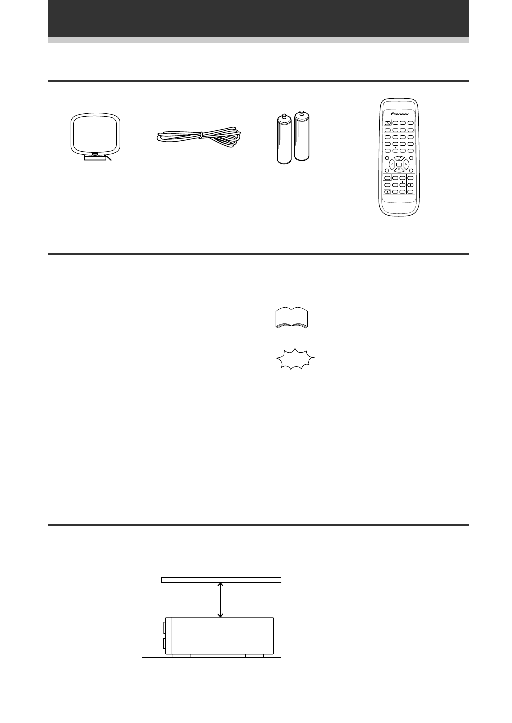
Checking the Supplied Accessories
Please check that you've received the following supplied accessories:
AM loop antenna FM wire antenna
Using this Manual
AA size IEC R6P
batteries (x2)
SOURCE SELECT
SOURCE
TUNER
DVD
CD
TV CONT.
MD
CD-R
TAPE
!
!
$
$
1234
*&#
569078
TV VOL.
CHANNEL
EFFECT
STATION
CLASS
D. ACCESS
MENU
TOP MENU
FQ
ENTER
TEST
MPX
TONE
SET UP
FQ
MUTING
DSP MODESORROUND
2
CH. SELECT
LEVEL
MASTER
FL
RECEIVER
FUNCTION
VOLUME
DIMMER
AV MULTI-CHANNEL RECEIVER
REMOTE CONTROL UNIT
Î
Remote control unit
This manual is for the VSX-D209 audio/video multichannel receiver. It is divided into two main
sections:
Set up
This section covers installing your receiver and
connecting up all the other components in your
memo
The following symbols are used
throughout this manual:
Provides detailed precautions and
advice on operations, etc.
home theater system to it. It also describes how to
set up a multi-channel speaker system to take full
advantage of the great surround sound features of
your receiver.
Indicates that display is blinking.
Operation
This section shows you how to use every feature
of the receiver and its remote control unit. It also
covers using the supplied remote control to operate
your other home theater components. To find out
more about a specific button, control or indicator,
see Displays & Controls starting on page 17. This
will point you to the relevant chapter in the manual.
In the Additional Information section (p.30-31) you'll
find a troubleshooting section and specifications.
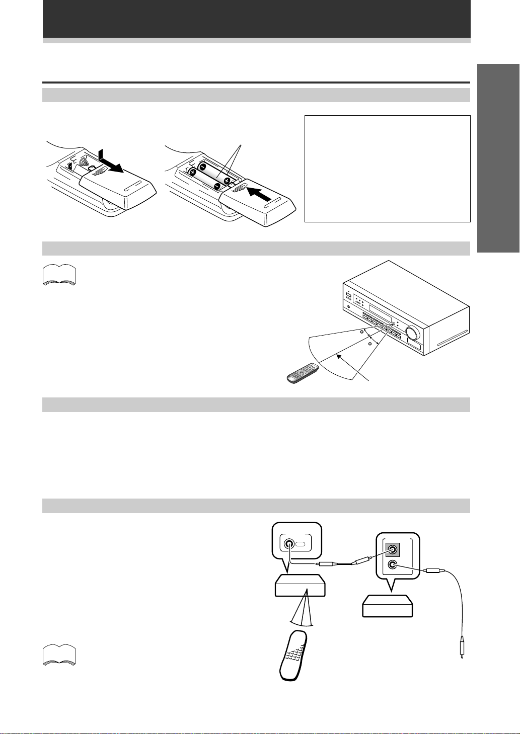
Installing the Receiver
Please note:
• Do not place objects directly on top of this unit. This would prevent proper heat dispersal.
• When installing in a rack, shelf, etc., be sure to leave more than 8 inches of space above the receiver .
8 inches (20 cm.)
Receiver
6
Page 7
Preparing the Remote Control
Loading the batteries
Introductory Information
Dry cell batteries
(AA size IEC R6P x 2)
CAUTION!
Incorrect use of batteries may result in such
hazards as leakage and bursting. Observe the
following precautions:
¶ Never use new and old batteries together.
¶ Insert the plus and minus sides of the
batteries properly according to the marks
in the battery case.
¶ Batteries with the same shape may have
different voltages. Do not use different
batteries together.
Operating range of remote control unit
memo
The remote control may not work properly if:
¶ There are obstacles between the remote control
and the receiver's remote sensor.
¶ Direct sunlight or fluorescent light is shining onto
the remote sensor.
¶ The receiver is located near a device that is
emitting infrared rays.
¶ The receiver is operated simultaneously with
another infrared remote control unit.
30
30
1 2 3
4 5 6
+
+
-
7m
The FUNCTION & SOURCE SELECT buttons on the remote control
Set up
Please note that the remote control has two types of buttons, one called FUNCTION and a set of buttons called
SOURCE SELECT. Use the FUNCTION button to choose the component you want to listen to (CD, CDR/TAPE,
TUNER, etc.) and use the SOURCE SELECT buttons to change which component the remote control itself will
operate. Thus, if the VSX-D209 is in TUNER mode, for example, and you want to listen to your CD player, you
need to select the CD mode with the FUNCTION button.
Operating other Pioneer components
By connecting a control cord (optional), you can
control other Pioneer equipment using this remote
control unit. Point the remote control unit towards
the remote sensor of this unit, even when operating
other equipment.
The remote control signals are received by the
remote sensor of this unit, and sent to the other
devices via the CONTROL OUT terminal.
memo
You can also control Pioneer components
by pointing the receiver's remote control
directly at the component. This type of
operation does not require control cords.
VSX-D209
Remote control unit
CONTROL
OUT
CONTROL
IN
OUT
Other Pioneer products
with Î mark
Connect to CONTROL IN
terminal of other Pioneer
products with Î mark.
7
Page 8
Connecting Your System
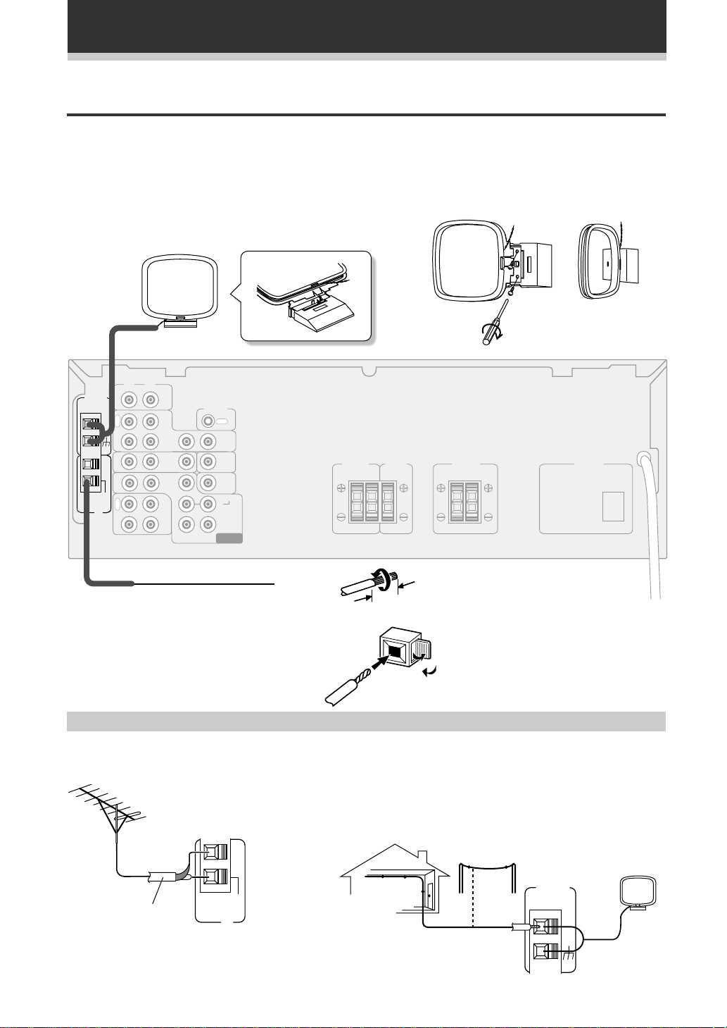
Connecting Antennas
Connect the AM loop antenna and the FM wire antenna as shown below. To improve reception and sound
quality, connect external antennas (see Using external antennas, below). Always make sure that the receiver is
switched off and unplugged from the wall outlet before making or changing any connections.
AM loop antenna
Assemble the antenna and connect to the receiver. Attach to
a wall, etc. (if desired) and face in the direction that gives the
best reception.
L
R
AM LOOP
ANTENNA
UNBAL
75Ω
FM
ANTENNA
IN
O
U
T
IN
IN
IN
FM
R
E
C
P
L
A
Y
VCR/
DVR
TV/
SAT
CD-R
/TAPE
/MD
CD
DVD
/LD
FRONT
OUT
IN
IN
IN
IN
SUB
WOOFER
CONTROL
OUT
OUT
TO
MONITOR
TV
SUB
WOOFER
PREOUT
SURROUND
LR
CENTER
DVD 5.1 CH
INPUT
CENTER
FRONT
SPEAKERS
SPEAKER
LRLR
SURROUND
SPEAKERS
AC OUTLET
FM wire antenna
Connect the FM wire antenna and fully extend
vertically along a window frame or other
suitable area, etc.
Using external antennas
7 To improve FM reception
Connect an external FM antenna.
FM
UNBAL
75 Ω coaxial cable
75Ω
FM
ANTENNA
8
3/8 in. (10mm)
Antenna snap connectors
Twist the exposed wire strands together
and insert into the hole, then snap the
connector shut.
7 To improve AM reception
Connect a 15-18 feet length of vinyl-coated wire to the AM antenna
terminal without disconnecting the supplied AM loop antenna.
For the best possible reception, suspend horizontally outdoors.
Outdoor antenna
AM LOOP
ANTENNA
Indoor antenna
(Vinyl-coated wire)
15-18 ft (5–6m)
Page 9
Connecting Your System
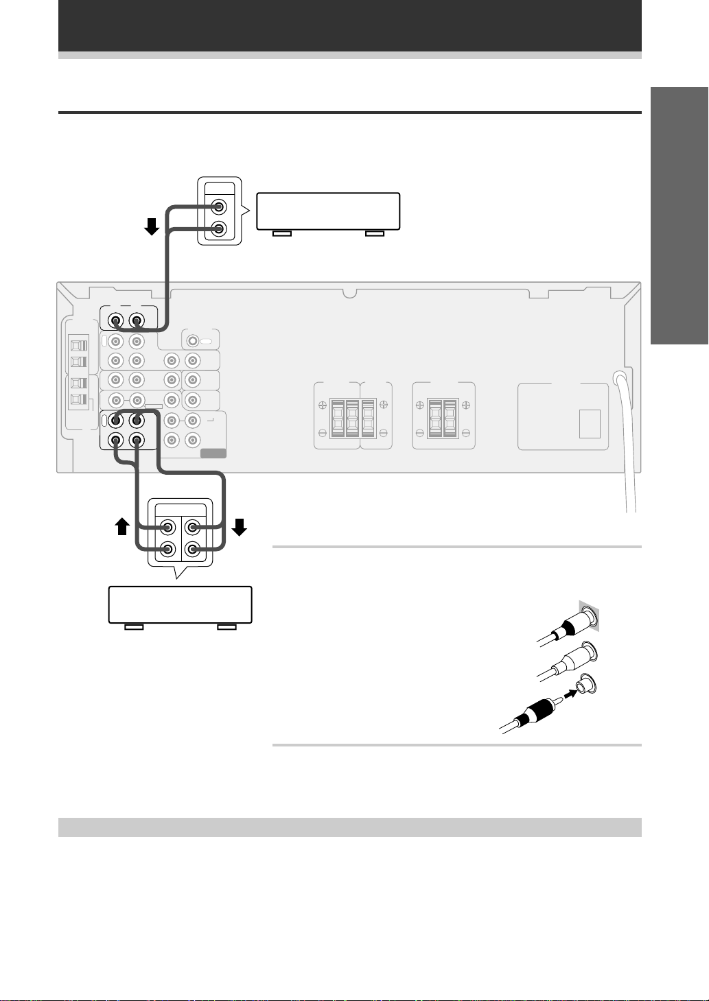
Connecting Audio Components
Connect your audio components as shown below. When connecting equipment, always make sure the power
switched off and the power cord is disconnected from the wall outlet.
AM LOOP
ANTENNA
UNBAL
75Ω
FM
ANTENNA
L
R
VCR/
DVR
TV/
SAT
CD-R
/TAPE
/MD
CD
DVD
/LD
FRONT
OUT
IN
IN
IN
IN
WOOFER
IN
O
U
T
IN
IN
IN
FM
R
E
C
P
L
A
Y
PLAY REC
CD-R, Cassette deck
MD, DAT etc.
OUT
L
CD player
Set up
R
CONTROL
OUT
TO
MONITOR
TV
SUB
WOOFER
PREOUT
SURROUND
LR
CENTER
SUB
DVD 5.1 CH
INPUT
SPEAKERS
CENTER
FRONT
SPEAKER
LRLR
SURROUND
SPEAKERS
AC OUTLET
L
R
Audio/Video cords
Use good quality audio/video cords with RCA/phono plugs at each end
to connect the audio or video components and a video cord to connect
the monitor/TV.
VIDEO
Connect red plugs to R (right), white plugs to
IN
L (left), and the yellow plugs to VIDEO.
L
Be sure to push home the plugs into their
sockets.
R
Cassette deck placement
Depending on where the cassette deck is placed, noise caused by leakage flux from the transformer in the
receiver may occur during playback. If you experience noise, move the cassette deck farther away from the
receiver.
9
Page 10
Connecting Your System
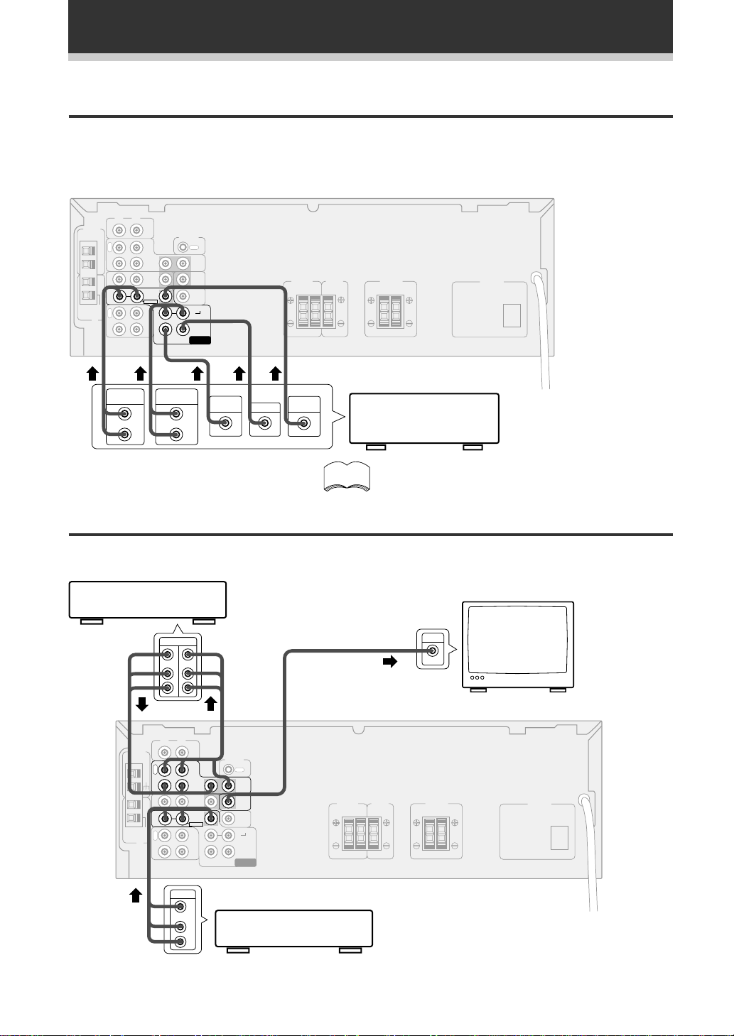
Connecting DVD 5.1 Channel Components
DVD and LD discs are compatible with both 2 channel and 5.1 channel audio output formats. Refer to page 21
for more information on how to switch between the two input methods. Connections can be made from a DVD
player, multi channel decoder equipped with 5.1 analog outputs to the 5.1 analog inputs on this unit. Always
make sure that the receiver is switched off and unplugged from the wall outlet before making or changing any
connections.
L
R
AM LOOP
ANTENNA
UNBAL
ANTENNA
FM
75Ω
FM
CD
IN
O
U
T
IN
IN
IN
R
E
C
P
L
A
Y
CONTROL
IN
IN
IN
SUB
WOOFER
OUT
TO
MONITOR
TV
SUB
WOOFER
PREOUT
SURROUND
LR
CENTER
DVD 5.1 CH
INPUT
CENTER
FRONT
SPEAKER
SPEAKERS
LRLR
SURROUND
SPEAKERS
AC OUTLET
VCR/
DVR
TV/
SAT
DVD
/LD
FRONT
OUT
CD-R
/TAPE
/MD
IN
L
R
SURROUND
OUT PUT
SUB
WOOFER
L
R
CENTER
VODEO
OUT
Components equipped
with 5.1 channel
analog output jacks
memo
The 5.1 channel input can only be used when DVD
5.1 CH is selected.
FRONT
OUT PUT
Connecting Video Components
Connect your video components as shown below. When connecting equipment, make sure the power is
switched off and the power cord disconnected from the wall outlet.
VCR, DVR, etc.
TV
monitor
AC OUTLET
AM LOOP
ANTENNA
UNBAL
ANTENNA
OUT IN
V
IN
VIDEO
L
R
L
R
CD
IN
O
U
T
IN
IN
IN
FM
R
E
75Ω
C
FM
P
L
A
Y
CONTROL
IN
IN
IN
SUB
WOOFER
OUT
OUT
TO
MONITOR
TV
SURROUND
LR
CENTER
DVD 5.1 CH
INPUT
CENTER
FRONT
SPEAKER
SPEAKERS
LRLR
SURROUND
SPEAKERS
VCR/
DVR
TV/
SAT
DVD
/LD
FRONT
OUT
CD-R
/TAPE
/MD
IN
10
OUT
V
L
DVD/LD player
R
Page 11

ª
·
Connecting Your System
Connecting Speakers
Connect your speakers as shown below. Be sure to connect each speaker to the appropriate speaker terminals,
and also to connect the positive and negative terminals correctly (positive to positive, negative to negative).
When connecting equipment, always make sure the power switched off and the power cord is disconnected
from the wall outlet.
• Use speakers with a nominal impedance of 8 Ω to 16 Ω.
Powered
Front
(left)
sub-woofer
INPUT
Front
(right)
Center
Set up
AM LOOP
ANTENNA
UNBAL
75Ω
FM
ANTENNA
L
R
VCR/
DVR
TV/
SAT
CD-R
/TAPE
/MD
IN
CD
DVD
/LD
FRONT
OUT
IN
IN
IN
SUB
WOOFER
CONTROL
OUT
OUT
TO
MONITOR
TV
SUB
WOOFER
PREOUT
SURROUND
LR
CENTER
DVD 5.1 CH
INPUT
Surround
(left)
CENTER
FRONT
SPEAKERS
SPEAKER
LRLR
SURROUND
SPEAKERS
AC OUTLET
Surround
(right)
IN
O
U
T
IN
IN
IN
FM
R
E
C
P
L
A
Y
Speaker terminals
Use good quality speaker wire to connect the speakers to the
receiver.
1 Twist around 1/2 inch of bare wire strands together.
2 Unclip the speaker terminal and insert the wire.
3 Snap shut the speaker terminal to secure.
11
Page 12

Connecting Your System
Hints on speaker placement
Speakers are usually designed with a particular placement in mind. Some are designed to be floorstanding, while
others should be placed on stands to sound their best. Some should be placed near a wall; others should be
placed away from walls. Follow the guidelines on placement that the speaker manufacturer provided with your
particular speakers to get the most out of them.
• Place the front left and right speakers at equal
distances from the TV.
• When placing speakers near the TV, we
recommend using magnetically shielded speakers
to prevent possible interference, such as
discoloration of the picture when the TV is switched
on. If you do not have magnetically shielded
speakers and notice discoloration of the TV picture,
move the speakers farther away from the TV.
• Install the center speaker above or below the TV
so that the sound of the center channel is localized
at the TV screen.
CAUTION!
If you choose to install the center speaker on
top of the TV, be sure to secure it with putty,
or by other suitable means, to reduce the risk
of damage or injury resulting from the speaker
falling from the TV in the event of external
shocks such as earthquakes.
• If possible, install the surround speakers slightly
above ear level.
• Try not to install the surround speakers farther away
from the listening position than the front and center
speakers. Doing so can weaken the surround sound
effect.
T o achieve the best possible surround sound, install
your speakers as shown below. Be sure all speakers
are installed securely to prevent accidents and
improve sound quality.
Front
Surround
Left
Left
Center
Listening
Position
Front
Right
Sub
Woofer
Surround
Right
3-D View of speaker set up
AC OUTLET [SWITCHED 100 W (0.8 A) MAX]
Power supplied through this outlet is turned on and off by the receiver's STANDBY/
ON button.
Total electrical power consumption of connected equipment should not exceed 100
W (0.8 A).
Do not connect a heater, TV, etc.
memo
12
• This unit should be disconnnected by removing the power plug from
the wall socket when not in regular use, e.g., on vacation.
• Do not connect appliances with high power consumption such as
heaters, irons, or television sets to this AC OUTLET in order to avoid
overheating and fire risk. This can also cause the receiver to malfunction.
CAUTION:
DO NOT CONNECT A MONITOR OR TV SET TO THIS UNIT'S AC OUTLET.
Page 13

Setting Up for Surround Sound
Setting Up for Surround Sound
The VSX-D209 offers several options for surround sound listening, depending on the speakers in your set up.
Having installed the speakers in your room it's important to set up the relative volume levels and delay time in
order to make the most of the receiver's surround sound capabilities. You only need to make these settings
once, unless you change the placement of your current speaker system or add new speakers, etc.
Setting the center mode, the subwoofer and speaker distances
It is important to set the type of center mode which corresponds to your speaker system, set the subwoofer on/
off and set speaker distances as well as set volume levels of each speaker. From your normal listening position,
the volumes of the various speakers in your system should appear to be equal. Follow the steps below to do all
of these things, especially adjust the volumes of the center and surround speakers relative to the main front
speakers for Dolby Pro Logic mode, 5.1 CH. mode and the DSP mode.
1
Switch on the receiver.
2
Press the SURROUND button.
SOURCE SELECT
2
1
SOURCE
TV CONT.
$
1234
TV FUNC.
56
TV VOL.
EFFECT
90
D. ACCESS
TOP MENU
TEST
TONE
CH. SELECT
RECEIVER
AV MULTI-CHANNEL RECEIVER
REMOTE CONTROL UNIT
DVD
TAPE
2
FUNCTION
*&#@
$
FQ
ENTER
FQ
LEVEL
CD
MD
!
78
CHANNEL
STATION
DSP MODESORROUND
FL
DIMMER
TUNER
MUTING
MASTER
VOLUME
3
CD-R
!
Press the 3 button to select the surround
sound setup mode.
Repeatedly pressing the button cycles through the three setup
modes (center mode setup; subwoofer setup; distance setup). The
mode appears in the display on the front panel.
CLASS
MENU
SET UP
MPX
Î
4
3
4
4
Use the 5∞ buttons to select one of the four
types of center mode.
See the center mode cycle shown here and the diagrams below
explaining each center mode to decide which center mode to
choose
NORMAL
3
3 STEREO
WIDE
22
3
33
PHANTOM2
2
Set up
1
Normal
Middle and high frequency sounds are heard
from the center speaker.
Bass frequencies from the center channel are
played through the front speakers.
Wide
If a full range speaker is used for the center
channel, all center channel sound, including
bass frequencies, are heard through the center
speaker.
Phantom
Center channel sounds are played through both
front speakers equally.
3 Stereo
Surround channel sounds and center channel
bass frequencies are heard through the front
stereo speakers.
13
Page 14

Setting Up for Surround Sound
5
6
SOURCE SELECT
SOURCE
TV CONT.
$
1234
TV FUNC.
56
TV VOL.
EFFECT
90
D. ACCESS
TOP MENU
TEST
TONE
CH. SELECT
RECEIVER
AV MULTI-CHANNEL RECEIVER
REMOTE CONTROL UNIT
DVD
TAPE
2
FUNCTION
*&#@
$
FQ
ENTER
FQ
LEVEL
CD
MD
!
78
CHANNEL
STATION
DSP MODESORROUND
FL
DIMMER
MUTING
MASTER
VOLUME
TUNER
CD-R
!
7
CLASS
MENU
SET UP
MPX
6
, 8,10
5,7,9
6, 8,10
Î
8
Press the 3 button to select the SUBWF
(subwoofer) select mode.
Use the 5∞ buttons to turn the subwoofer
function on or off.
Select SUBWF ON if you have a subwoofer and SUBWF OFF if
you don't have a subwoofer.
Press the 3 button to select the distance
mode for the FRNT (front) speakers.
For true surround sound effect the sound from the front speakers
and the surround speakers should arrive to the listener's ears at a
slightly different time. Telling the receiver how far your front and
surround speakers are from your listening position will allow for
this. The first distance setting you'll see will be FRNT for your front
speakers. You can set the distance in a range from 1-30 feet.
Press the 5∞ buttons to increase/decrease
the distance of the FRNT speakers.
You need to judge(or measure) how far the speakers are from your
normal listening position and set the distance accordingly. You can
set the distance in a range from 1-30 feet.
9
Press the 3 button to select the distance
mode for the SURR (surround) speakers.
10
Press the 5∞ buttons to increase/decrease
the distance of the SURR speakers.
Again, You need to judge how far the speakers are from your
normal listening position and set the distance accordingly. As
above, you can set the distance in a range from 1-30 feet.
When you are finished setting up the delay time the receiver will
return to normal operating mode after about 20 seconds.
Alternatively, you can cycle through the options with the 2 3
buttons until you return to the regular operating mode.
memo
Y ou only need to make the distance settings if your system
has surround speakers.
14
Page 15

Setting Up for Surround Sound
Setting up speaker levels for Dolby Pro Logic
In order to get the best surround sound you need to set up the relative speaker levels so that they all have the
same volume from your normal listening position. Follow the steps below using the TEST TONE to do this.
1
Press the 2 button.
2
Press the SURROUND button.
3
Press the TEST TONE button.
A short test tone will be heard in turn from each speaker in your set
up. No test tone is heard from the sub woofer, however.
4
Adjust the respective speaker levels with the
LEVEL +/– buttons when the TEST TONE
sounds from that speaker.
Adjust the volumes of the speakers so that the volume of all speakers
appears equal from your normal listening position.
5
Press TEST TONE again.
When you are satisfied that the set up is complete, press the TEST
TONE button to return to normal operation.
3, 5
2
1
SOURCE SELECT
SOURCE
DVD
CD
TV CONT.
MD
TAPE
!
$
$
1234
TV FUNC.
*&#@
56
78
TV VOL.
CHANNEL
EFFECT
2
FUNCTION
STATION
FQ
ENTER
FQ
DSP MODESORROUND
LEVEL
FL
DIMMER
90
D. ACCESS
TOP MENU
TEST
TONE
CH. SELECT
RECEIVER
AV MULTI-CHANNEL RECEIVER
REMOTE CONTROL UNIT
MUTING
MASTER
VOLUME
TUNER
CD-R
CLASS
MENU
SET UP
!
MPX
4
Î
Set up
memo
• No TEST TONE sounds for the subwoofer
• These speaker level settings are applicable to PRO LOGIC,
PRO LOGIC THEATER 1 & PRO LOGIC THEATER 2
settings.
Setting up speaker levels for DVD CH 5.1
1
Use the FUNCTION button to select DVD 5.1
CH input mode.
2
Play a DVD 5.1 CH source and set master
volume to a moderate level.
3, 5
7
1
,
SOURCE SELECT
SOURCE
DVD
CD
TV CONT.
TV FUNC.
D. ACCESS
TOP MENU
TEST
TONE
CH. SELECT
RECEIVER
AV MULTI-CHANNEL RECEIVER
REMOTE CONTROL UNIT
MD
TAPE
!
$
$
1234
*&#@
56
78
TV VOL.
CHANNEL
EFFECT
2
FUNCTION
STATION
FQ
ENTER
FQ
DSP MODESORROUND
LEVEL
FL
DIMMER
90
TUNER
MUTING
MASTER
VOLUME
CD-R
CLASS
MENU
SET UP
!
MPX
Î
4, 6
7
2
3
Press the CH. SELECT button.
The first speaker, FL (front left), and its relative volume level (+/–
**dB) appears in the display.
4
Adjust the front left (FL) speaker level with the
LEVEL +/– buttons.
Adjust the volumes of the speakers to a standard level of your choice
when seated in your normal listening position.
5
Press CH. SELECT again to move to the next
speaker.
,
The second speaker CT (center) and its relative volume level (+/–
**dB) appears in the display.
6
Adjust the center (CT) speaker level with the
LEVEL +/– buttons.
Adjust the speaker volume so it seems the same as the previous
speaker from your normal listening position.
7
Repeat steps 3 & 4 for all of your speakers.
Adjust the volumes of the all speakers so their volume seems the
same from your normal listening position.
15
Page 16

Setting Up for Surround Sound
Setting up speaker levels for DSP
1
Use the DSP MODE button to turn on a DSP
effect. You can cycle through the five
different types with the DSP button.
2
Play a source (CD, tape,etc.) and set master
volume to a moderate level.
3
Press the CH. SELECT button.
The first speaker FL (front left) and it's relative volume level (+/**dB) appears in the display.
4
Adjust the front left (FL) speaker level with
the LEVEL +/– buttons.
Adjust the volumes of the speakers to a standard level of your
choice when seated in your normal listening position.
5 Press CH. SELECT again to move to the next
3, 5,
7
SOURCE SELECT
SOURCE
DVD
CD
TV CONT.
TV FUNC.
D. ACCESS
TOP MENU
TEST
TONE
CH. SELECT
RECEIVER
AV MULTI-CHANNEL RECEIVER
REMOTE CONTROL UNIT
MD
TAPE
!
$
$
1234
*&#@
56
78
TV VOL.
CHANNEL
EFFECT
2
FUNCTION
STATION
FQ
ENTER
FQ
DSP MODESORROUND
LEVEL
FL
DIMMER
90
MUTING
MASTER
VOLUME
TUNER
CD-R
CLASS
MENU
SET UP
!
MPX
1
4, 6,
Î
7
speaker.
2
The second speaker CT (center) and it's relative volume level (+/**dB) appears in the display.
6
Adjust the center (CT) speaker level with the
LEVEL +/– buttons.
Adjust the volume of the speaker so its volume seems the same as
the previous speaker from your normal listening position.
7
Repeat steps 3 & 4 for all of your speakers.
Adjust the volumes of the all speakers so their volume seems the
same from your normal listening position.
memo
• These speaker level settings are applicable to DSP effects
only.
• Each effect level applies only to the DSP type (HALL for
example) that it is set in. Y ou can set the effect levels for
each type independently.
16
Page 17

Displays & Controls
Front Panel
123456
~! ^%=$@#
1 STANDBY/ON button
Switches the receiver between on and standby.
2 STANDBY indicator
Lights when the receiver is in standby mode
(note that the receiver consumes a small amount
of power (1W) in standby mode).
3 STA TION (+/–), FREQUENCY (+/–), TUNING
SELECT buttons (see pages 23–25)
STATION (+/–)
Selects station memories when using the tuner.
FREQUENCY (+/–)
Selects the frequency when using the tuner.
TUNING SELECT
Switches between station memory and
frequency select modes.
4 CLASS button (see page 25)
Switches between the three banks (classes) of
station memories.
5 MEMORY button (see page 24)
Press to memorize a station for recall using the
STATION (+/–) buttons.
6 MPX MODE button (see page 23)
lf the TUNED or STEREO indicators don't light
when tuning to an FM station because the signal
is weak, press the MPX button to switch the
receiver into mono reception mode. This should
improve the sound quality and allow you to enjoy
the broadcast.
7 Display (see page 18)
8 Remote sensor
Receives the signals from the remote control.
9 DSP MODE button (see page 22)
Use to switch between the various DSP modes
available (HALL, JAZZ, DANCE, THEATER1,
THEATER2) and DSP off. Use to create different
surround sound effects from any stereo source.
7
8
9
0
-
0 DOLBY PRO LOGIC button (see page 20)
Use to switch between the various Pro Logic
modes (PRO LOGIC, PRO LOGIC THEATER1,
PRO LOGIC THEATER2) and Pro Logic off.
- MASTER VOLUME
Use to set the overall listening volume.
= PHONES jack
Use to connect headphones but this does not
switch the speakers off.
~ SPEAKER button
Use to switch the speaker system on or off.
! FL DIMMER button
Use this button to make the fluorescent display
(FL) dimmer or brighter. There are three
brightness settings as well as an off setting.
@ BASS (+/–) buttons
Use to increase/decrease bass (within a range of
–6dB to 6dB in 2dB steps). It cannot be used
when S.BASS is on.
# TREBLE (+/–) buttons
Use to increase/decrease treble (within a range of
–6dB to 6dB in 2dB steps).
$ Function buttons
Use to select a source for playback or recording.
% S.BASS button
Use to switch on and off the bass boost. Use for
a more powerful bass sound. Negates use of
BASS buttons.
^ DIRECT button
Use to switch DIRECT playback on or off. This
mode bypasses the tone controls and channel
levels for the most accurate reproduction of a
program source.
Set up
Operation
17
Page 18

Displays & Controls
Display
12 435
PRO LOGIC DSP DIRECT MONITOR
1 2 PRO LOGIC indicator
Lights when any Dolby Pro Logic mode is
selected.
The main character display briefly shows the
current Pro Logic mode (PRO LOGIC,
THEATER1, THEATER2) after selection (see
page 20).
2 DSP indicator
Lights when any DSP mode is selected. The
main character display briefly shows the current
DSP mode (HALL, JAZZ, DANCE, THEATER1
and THEATER2) after selection (see page 22).
3 DIRECT indicator
Lights when source DIRECT is on. This function
bypasses all tone, balance, DSP and Dolby
Surround effects.
4 MONITOR indicator
Lights when MONITOR is selected to hear a
recording as it's being made (see page. 26).
5 TUNER indicators
MONO:
Lights when the mono mode is set using the
MPX MODE button (see page. 23).
TUNED:
Lights when a broadcast is being received.
STEREO:
Lights when a stereo FM broadcast is being
received in auto stereo mode.
MONO
S. BASS
SP A STEREO
TUNED
6 MASTER VOLUME LEVEL
Shows the overall volume level. Volume level is
maintained even when the power is off. ---dB
indicates the minimum level, and 0dB indicates
the maximum level.
• Depending on the level settings for
individual channels, the MAX level can
range between –10dB and 0dB.
7 SPEAKER indicator
Shows if the speaker system is on or not. If
SP3A appears speakers are switched on.
If SP3 appears speakers are switched off.
8 S. BASS indicator
Lights when the S. BASS is on (see note %
page.17).
9 CHARACTER display
Shows the radio frequency or function (DVD/LD,
CD, etc.) receiver is using .
dB
6789
18
Page 19

Remote Control
SOURCE SELECT
1
2
SOURCE
TV CONT.
$
1234
TV FUNC.
56
TV VOL.
EFFECT
90
D. ACCESS
TOP MENU
3
TEST
TONE
4
5
6
7
8
CH. SELECT
RECEIVER
FUNCTION
AV MULTI-CHANNEL RECEIVER
REMOTE CONTROL UNIT
9
1 SOURCE (Power) button
This button turns on/off the power for PIONEER
components connected to the VSX-D209.
2 NUMBER/PLAYER COMMAND
buttons (see page 24, 27-29)
Use to select the radio frequency in tuner mode.
Also, you can use to contol PIONEER
components like CD players, cassette decks,
etc. according to the comands printed above the
button (4, 3, 7, etc.)
3 D.ACCESS/TOP MENU button (see
page 24, 29)
This button gives you direct access to radio
frequency input, allowing you to input a station
directly. In DVD mode this button brings you to
the top menu.
4 TEST TONE button (see page 15 & 23-
24)
Use this button to hear a test tone from each
speaker in turn to set the relative speaker
volumes. Also switches the BAND in TUNER
mode.
5 SURROUND button (see page 13,15,
20, 22)
Use this button to set up the surround sound
features of the VSX-D209. In particular, it's used
to select the type of center mode, turn on/off
subwoofer option and select delay time for each
speaker. Also used to start the process of
setting the effect levels
6 2 button (see page 15, 20)
Use to select a Dolby Pro Logic mode. Also used
to access Test Tone.
DVD
TAPE
2
*&#@
$
FQ
ENTER
FQ
DSP MODESORROUND
LEVEL
DIMMER
TUNER
CD
MD
CD-R
!
78
CHANNEL
STATION
CLASS
MENU
SET UP
MUTING
FL
MASTER
VOLUME
0
!
=
~
MPX
!
@
#
$
Î
%
^
Displays & Controls
7 CH. SELECT button (see page 15-16, )
Used to start the process of setting the speaker
levels (see $ below).
8 RECEIVER STANDBY/ON button
Use to switch the receiver between on and
standby modes.
9 FUNCTION button
Use select the playback or recording source.
0 SOURCE SELECT keys
Use to put the remote control (NOT the
receiver) in the stated mode.
For other equipment controls, see Controlling
the Rest of Your System starting on page 27.
- CHANNEL/STATION +/– buttons (see
page.25, 27)
Use to select the station of memorized
frequencies or change channels on Pioneermade TVs.
= CLASS/MENU button (see page. 25, 29)
Use to switch between the three banks (classes)
of station memories.
~ 2 3 5∞ ( FQ +/–) & ENTER buttons
(see page.13, 14, 23)
Use these arrow buttons when setting up your
surround sound system (see page. 13-16). These
buttons are also used to control DVD menus/
options and for deck 1 of a double cassette deck
player. The FQ +/- buttons can be used to find
radio frequencies.
! MPX/SETUP MODE button (see page
23, 29)
Use to switch between auto stereo and mono
reception of FM broadcasts. If the signal is weak
then switching to MONO will improve the sound
quality. In DVD mode this button brings up the
SETUP menus.
@ DSP MODE button (see page 22)
Use to switch between the various DSP modes
available (HALL, JAZZ, DANCE, THEATER1,
THEATER2) and DSP off. Use to create different
surround sound effects from any stereo source.
# MUTING button
Use to mute all audio without affecting any of
the current sound settings.
$ +/– LEVEL buttons (see page 15, 16)
Use to set the relative speaker volumes for all
the speakers in your system (see 7 above).
% MASTER VOLUME +/– buttons
Use to set the overall listening volume.
^ FL DIMMER button
Use this button to make the fluorescent display
(FL) dimmer or brighter. There are three
brightness settings as well as an off setting.
Operation
19
Page 20

Listening in Surround Sound
Listening in Dolby Pro Logic Mode
To really appreciate what the VSX-D209 can do, sit back and experience a movie encoded in Dolby Digital or
Dolby Pro Logic with five speaker surround sound creating theater-like sound effects in your living room. When
choosing software, look out for the
(sometimes, unmarked software is also recorded in Dolby Pro Logic).
To enjoy Dolby Digital surround sound from DVD discs, you'll need to have connected your DVD player (or Dolby
Digital decoder) to the receiver's 5.1 channel inputs (see page 10), and set the receiver to DVD 5.1CH input
mode. Turn to page 21 for more on this.
Many video tapes feature Dolby Surround/Pro Logic these days. The VSX-D209 takes advantage of this to
provide dramatic and realistic surround sound. The effect can be further enhanced by choosing a Pro Logic with
DSP mode. Follow the steps on this page when playing Dolby Surround or Dolby Pro Logic material.
When using any of these modes, it's really important that your speakers are set up correctly (see page. 11-12),
and that you've worked through the steps in Setting Up for Surround Sound on pages 13-15.
1
Press 2 (DOLBY PRO LOGIC on the
receiver).
Pressing repeatedly changes the Pro Logic mode in the following
sequence:
2
Press SURROUND.
This starts the process of setting the effect level.
3 Use the EFFECT +/– to adjust the DSP effect
level PRO LOGIC THEATER1 and PRO LOGIC
THEATER2 .
You can adjust the effect level within an range of 10–90 (the default
settinig is 50).
3
2
1
SOURCE SELECT
SOURCE
DVD
CD
TV CONT.
TV FUNC.
D. ACCESS
TOP MENU
TEST
TONE
CH. SELECT
RECEIVER
AV MULTI-CHANNEL RECEIVER
REMOTE CONTROL UNIT
MD
TAPE
!
$
$
1234
*&#@
56
78
TV VOL.
CHANNEL
EFFECT
2
FUNCTION
STATION
FQ
ENTER
FQ
DSP MODESORROUND
LEVEL
FL
DIMMER
90
MUTING
MASTER
VOLUME
TUNER
CD-R
CLASS
MENU
SET UP
!
MPX
Î
mark on DVD discs, laser discs, and video tapes
DOLBY
PRO
3 3
LOGIC
SURR OFF
2
PRO LOGIC
THEATER
1
PRO LOGIC
THEATER
2
2
20
1
memo
• You need to input mode/distance/level settings specifically
for your Pro Logic mode (see page. 13-15).
• If you turn the speakers off PRO LOGIC goes off as well.
When you turn the speakers back on, PRO LOGIC will NOT
go back on.
• If you try and turn PRO LOGIC on when the speakes are off,
SP OFF will flash on the display, informing you that you can't
turn on PRO LOGIC when the speakers are off.
• You can't use the tone controls, or the DIRECT function
with PRO LOGIC mode.
Page 21

Listening in Surround Sound
Listening in DVD 5.1 Channel Input Mode
You can use this feature if you have a DVD player and a Dolby Digital decoder or a DVD player with a built-in
Dolby Digital decoder. Both these decoders will have separate analog audio outputs for the front left and right,
center, surround left and right, and sub-woofer channels. Connect these to the 5.1 channel inputs of the VSXD209 for enhanced playback of Dolby Digital material—see page 10 for instructions on connecting up. 5.1
channel mode of the VSX–D209 provides better surround-channel sound and overall channel separation than the
Dolby Pro Logic mode.
Follow the steps below to use the 5.1 channel mode.
1
Use the FUNCTION button to select DVD 5.1
CH.
On the receiver, press the DVD 5.1 CH function button to select
the DVD input mode directly.
On the remote control, repeated presses of the FUNCTION button
switches between 5.1 channel input and the other inputs.
memo
• You can input level settings spefically for the 5.1 CH mode
and this will enhance you surround sound experience see
p.15).
• You can't use the tone controls S.BASS, or the DIRECT
function in 5.1 CH mode.
1
SOURCE SELECT
SOURCE
DVD
CD
TV CONT.
TV FUNC.
D. ACCESS
TOP MENU
TEST
TONE
CH. SELECT
RECEIVER
AV MULTI-CHANNEL RECEIVER
REMOTE CONTROL UNIT
MD
TAPE
!
$
$
1234
*&#@
56
78
TV VOL.
CHANNEL
EFFECT
2
FUNCTION
STATION
FQ
ENTER
FQ
DSP MODESORROUND
LEVEL
FL
DIMMER
90
TUNER
MUTING
MASTER
VOLUME
CD-R
!
CLASS
MENU
MPX
SET UP
Î
Operation
1
21
Page 22

Listening in Surround Sound
Listening in DSP Mode
The DSP (Digital Signal Processing) modes transform your living room into a variety of different sound
environments when playing standard (two channel) stereo sources. Optionally, you can adjust the amount of
effect added to the source. The descriptions below give an idea of what the five different modes sound like, but
the best idea is to play a source and experiment.
HALL
Simulates the acoustic environment of a large
classical concert hall. Long delay and reverb decay
times create a sense of music being played in a
large space.
JAZZ
Simulates the acoustic environment of a jazz club.
Shorter delay times and a tighter reverb help to give
the sound a live, small club feel.
1
Use to DSP MODE button to select a DSP
MODE.
Repeated presses of DSP MODE changes the DSP mode in the
following sequence:
2
Press the SURROUND button.
3
Use the EFFECT +/– buttons to adjust the
DSP effect level.
You can adjust the effect level within an range of 10–90 (the default
settinig is 50).
3
2
SOURCE SELECT
SOURCE
DVD
CD
TV CONT.
TV FUNC.
D. ACCESS
TOP MENU
TEST
TONE
CH. SELECT
RECEIVER
AV MULTI-CHANNEL RECEIVER
REMOTE CONTROL UNIT
MD
TAPE
!
$
$
1234
*&#@
56
78
TV VOL.
CHANNEL
EFFECT
2
FUNCTION
STATION
FQ
ENTER
FQ
DSP MODESORROUND
LEVEL
FL
DIMMER
90
MUTING
MASTER
VOLUME
TUNER
CD-R
CLASS
MENU
SET UP
!
MPX
1
Î
DANCE
Simulates the acoustic environment and strong bass
sound of a dance music club.
THEATER 1
Simulates the acoustic environment of a mid-sized
movie theater.
THEATER 2
Similar to the above but maintains proper
localization of each channel.
3
DSP
OFF
HALL
2
JAZZ
3
THEATER 2
2
DANCE
3
THEATER 1
2
22
1
memo
• The settings for effect level in DSP mode are independent
of the effect level in PRO LOGIC THEA TER1 and PRO LOGIC
THEATER2 modes.
• Y ou can input level settings spefically for the DSP mode and
this will enhance you surround sound experience (see page.
16).
• If you try and turn DSP on when the speakes are off, SP
OFF will flash on the display, informing you that you can't
turn on DSP when the speakers are off.
• You can't use the tone controls, or the DIRECT function
with DSP mode.
Page 23

Using the Tuner
Finding a Station
The following steps show you how to tune in to FM and AM radio broadcasts using the automatic (search) and
manual (step) tuning functions. If you already know the exact frequency of the station you want to listen to, see
Tuning Directly to a Station on the following page. Once you are tuned to a station you can memorize the
frequency for recall later—see Memorizing Stations on page 24 for more on how to do this.
1
Use the FUNCTION button to put the receiver
in tuner mode .
On the receiver, press the FM/AM button to select the tuner
mode.
2
Press the TUNER button on the remote
control to put the remote control in tuner
mode.
3
Use the TEST TONE button to change the
band (FM or AM), if necessary.
Each press switches the band between FM and AM (on the front
panel use the FM/AM button).
4
Tune to a station.
Automatic tuning
To search for stations in the currently selected band, press and hold
either the FQ.
will start searching for the next station, stopping when it has found
one. Repeat this step to search for other stations.
Manual tuning
To change the frequency one step at a time, press the FQ.
– (5∞) buttons.
To change frequency more quickly, press and hold the FQ.
– buttons until the desired frequency is reached, then release.
Once you've found a station, you can store it in the receiver's
memory for easy recall anytime—turn to page 25 for more on this.
+ or FQ. – button for about a second. The receiver
+ / FQ.
+ / FQ.
3
1
4
SOURCE
TV CONT.
$
1234
TV FUNC.
56
TV VOL.
EFFECT
90
D. ACCESS
TOP MENU
TEST
TONE
CH. SELECT
RECEIVER
FUNCTION
AV MULTI-CHANNEL RECEIVER
REMOTE CONTROL UNIT
MPX
SOURCE SELECT
DVD
TAPE
$
*&#@
ENTER
2
LEVEL
!
FQ
FQ
DSP MODESORROUND
DIMMER
TUNER
CD
MD
CD-R
78
CHANNEL
STATION
CLASS
MENU
SET UP
MUTING
MASTER
FL
VOLUME
1
2
!
4
MPX
MPX
4
Î
Operation
MPX mode
If the TUNED or STEREO indicators don't light when tuning to an FM
station because the signal is weak, press the MPX button to switch the
receiver into mono reception mode. This should improve the sound
quality and allow you to enjoy the broadcast.
23
Page 24

Using the Tuner
Tuning Directly to a Station
Sometimes, you'll already know the frequency of the station you want to listen. In this case, you can simply
enter the frequency directly using the number buttons on the remote control (this function is not available using
the front panel controls of the receiver).
1
Use the FUNCTION button to put the receiver
in tuner mode .
On the receiver, press the FM/AM button to select the tuner
mode.
2
Press the TUNER button on the remote
control to put the remote control in tuner
mode.
3
Press the TEST TONE button to select either
FM or AM.
Each press switches the band between FM and AM.
On the receiver, pressing the FM/AM button switches between
bands.
4
Press D.ACCESS (DIRECT ACCESS).
4
3
1
SOURCE SELECT
SOURCE
DVD
CD
TV CONT.
TV FUNC.
D. ACCESS
TOP MENU
TEST
TONE
CH. SELECT
RECEIVER
AV MULTI-CHANNEL RECEIVER
REMOTE CONTROL UNIT
MD
TAPE
!
$
$
1234
*&#@
56
78
TV VOL.
CHANNEL
EFFECT
2
FUNCTION
STATION
FQ
ENTER
FQ
DSP MODESORROUND
LEVEL
FL
DIMMER
90
TUNER
MUTING
MASTER
VOLUME
CD-R
2
!
5
CLASS
MENU
MPX
SET UP
Î
5
Use the number buttons to enter the
frequency of the radio station.
1, 3
Example:
To tune to 106.00 (FM), press 1 – 0 – 6 – 0 – 0
TUNED
A
STEREO
SP
If you make a mistake while inputting the frequency, press the
D.ACCESS button twice to cancel the frequency and start again.
Memorizing Stations (front panel only)
If you often listen to a particular radio station, it's convenient to have the receiver store the frequency for easy
recall whenever you want to listen to that station. This saves the effort of manually tuning in each time. The VSXD209 can memorize up to 30 stations, stored in three banks, or classes, (A,B and C) of 10 stations each. When
memorizing FM frequencies, the receiver also stores the MPX setting (auto stereo or mono, see page.23). The
process for memorizing stations is only possible from the controls on the front panel of the receiver.
1
3 2 4
Tune to a station you want to memorize.
See Finding a Station and Tuning Directly to a Station, on pages 23
and this page, for more on how to do this.
2
Press MEMORY.
The display shows a blinking memory class.
TUNED
A
SP
STEREO
24
(continues on next page)
Page 25

Using the Tuner
3
Press CLASS to select one of the three
3 2 4
classes.
Repeatedly pressing this button cycles through the three available
classes, A, B and C.
4
Press STATION +/– to select the desired
station memory number.
Pressing these buttons repeatedly cycles through the 10 available
station memories in each class.
After choosing the location you want, the preset class and number
blink for about 5 seconds and the receiver stores the station.
Repeat steps 1 to 4 to memorize up to 30 stations.
Recalling Memorized Stations
Having memorized up to 30 stations (see the previous page for how to do this), you can be listening to a station
with a couple of button presses.
1
Use the FUNCTION button to put the receiver
in tuner mode .
On the receiver, press the FM/AM button to select the tuner
mode.
2
Press the TUNER button on the remote
control to put the remote control in tuner
mode.
3
Press CLASS to select the class in which the
station is stored.
Repeatedly pressing this button cycles through the three available
classes, A, B and C.
4
Use the STATION +/– buttons to select the
station memory in which the station is
stored.
Alternatively, recall the station memory using the number buttons
on the remote control.
1
SOURCE SELECT
SOURCE
DVD
CD
TV CONT.
TV FUNC.
D. ACCESS
TOP MENU
TEST
TONE
CH. SELECT
RECEIVER
AV MULTI-CHANNEL RECEIVER
REMOTE CONTROL UNIT
MD
TAPE
!
$
$
1234
*&#@
56
78
TV VOL.
CHANNEL
EFFECT
2
FUNCTION
STATION
FQ
ENTER
FQ
DSP MODESORROUND
LEVEL
FL
DIMMER
90
TUNER
MUTING
MASTER
VOLUME
CD-R
CLASS
MENU
SET UP
2
!
4
3
MPX
Î
Operation
34 1
memo
If the receiver is left disconnected from the AC power outlet
for a lengthy period, the station memories will be lost and will
have to be reprogrammed.
25
Page 26

Making a Recording
Making an Audio or a Video Recording
The following steps show you how to make an audio or a video recording from the built in tuner, or from an
audio or video source connected to the receiver (such as a CD player or TV). Recordings can be made to a CDRecorder, cassette deck, MD, VCR, or DVR deck connected to the CD-R/TAPE/MD, VCR or DVR in/out
connectors.
memo
1
The receiver's volume, balance tone (bass, treble, S.bass), and surround effects (Dolby Pro Logic
and DSP settings) have no effect on the recorded signal.
1
Press the FUNCTION button to select a
source to record.
SOURCE SELECT
SOURCE
DVD
CD
TV CONT.
TV FUNC.
D. ACCESS
TOP MENU
TEST
TONE
CH. SELECT
RECEIVER
AV MULTI-CHANNEL RECEIVER
REMOTE CONTROL UNIT
MD
TAPE
!
$
$
1234
*&#@
56
78
TV VOL.
CHANNEL
EFFECT
2
FUNCTION
STATION
FQ
ENTER
FQ
DSP MODESORROUND
LEVEL
FL
DIMMER
90
TUNER
MUTING
MASTER
VOLUME
CD-R
!
CLASS
MENU
MPX
SET UP
Î
All functions except MONITOR are accessible from the remote
control.
On the receiver, select the source directly using the front panel
buttons.
2
Prepare the program source.
Tune to the radio station, load the CD, etc. For a video recording
load the video, DVD etc.
3
Insert a blank tape, MD, video etc. into the
recording device connected to either CD-R/
TAPE/MD or VCR/DVR and set the recording
levels.
Refer to the instructions that came with the recorder if you are
unsure how to do this.Most video recorders set the audio recording
level automatically—check your video's instruction manual if you
are unsure whether yours has manual controls.
4
Start recording, then start playback of the
source component.
26
1
Record MONITOR
You can listen to (monitor) the recording as it's being made using the
MONITOR button on the Front Panel (a cassette deck would have to
have a record monitor function).
Press the MONITOR button to switch between the recorded signal and
the original source signal.
MONITOR
Page 27

Controlling the Rest of Your System
CD/MD/CD-R Player Controls
memo
This remote control can control Pioneer CD, MD or CD-R decks.
To control your CD, MD or CD-R player with this remote control, first put the remote into CD, MD
or CD-R mode with the proper SOURCE SELECT button (i.e. the CD, MD, or CD-R button).
1
SOURCE SELECT
SOURCE
DVD
CD
2
3
4
5
6
TV CONT.
$
1234
TV FUNC.
56
TV VOL.
EFFECT
90
D. ACCESS
TOP MENU
TEST
TONE
CH. SELECT
FUNCTION
RECEIVER
AV MULTI-CHANNEL RECEIVER
REMOTE CONTROL UNIT
TUNER
TAPE
MD
CD-R
!
!
2
*&#@
$
FQ
ENTER
FQ
LEVEL
78
CHANNEL
STATION
DSP MODESORROUND
FL
DIMMER
MUTING
MASTER
VOLUME
CLASS
MENU
SET UP
Î
MPX
7
8
9
0
1 Use SOURCE SELECT buttons to
put the remote control in the
stated mode.
2 SOURCE
(power)
Press to switch the CD, MD or CD-R player
between STANDBY and ON.
3 4
Press to return to the start of the current track.
Repeated presses skips to the start of previous
tracks.
4 ¢
Press to advance to the start of the next track.
Repeated presses skips to the start of following
tracks.
5 2
This button has no function.
6 8
Press to pause playback.
7 ¡
Hold down for fast forward playback.
8 1
Hold down for fast reverse playback.
9 3
Press to start playback.
0 7
Press to stop playback (on some models,
pressing this when the disc is already stopped
will cause the disc tray to open).
Operation
TV Controls
memo
This remote control can control Pioneer TVs.
To control your TV with this remote control, first put the remote into TV mode with the TV CONT
SOURCE SELECT button.
1
2
3
4
SOURCE
TAPE
TV CONT.
$
1234
TV FUNC.
56
TV VOL.
EFFECT
90
D. ACCESS
TOP MENU
TEST
TONE
CH. SELECT
FUNCTION
RECEIVER
AV MULTI-CHANNEL RECEIVER
REMOTE CONTROL UNIT
SOURCE SELECT
DVD
$
*&#@
ENTER
2
LEVEL
FQ
FQ
DSP MODESORROUND
DIMMER
CD
MD
!
FL
TUNER
CD-R
78
CHANNEL
STATION
CLASS
MENU
MPX
SET UP
MUTING
MASTER
VOLUME
Î
1 Use SOURCE SELECT buttons to
put the remote control in the
stated mode.
2 SOURCE
!
Press to switch the TV or CATV between
STANDBY and ON.
(power)
3 TV FUNC. (TV only)
5
Press to switch the TV input (not possible with
all models)..
4 TV VOL +/–
Use to adjust the TV volume.
5 CHANNEL +/–
Use to select channels.
27
Page 28

Controlling the Rest of Your System
Cassette Deck Controls
memo
1
2
3
4
5
6
This remote control can control Pioneer cassete decks.
To control your cassette deck with this remote control, first put the remote into the TAPE mode
with the TAPE SOURCE SELECT button.
For regular cassette decks use buttons 3-0 below for the tape control functions. For double
deck models, use buttons 3-0 to control deck 2 and buttons --= to control deck 1.
4 ¢
This button has no function in cassette deck
mode.
SOURCE SELECT
SOURCE
DVD
CD
TAPE
TV CONT.
$
1234
TV FUNC.
56
90
D. ACCESS
TOP MENU
TEST
TONE
CH. SELECT
RECEIVER
AV MULTI-CHANNEL RECEIVER
REMOTE CONTROL UNIT
TV VOL.
EFFECT
*&#@
2
FUNCTION
$
FQ
ENTER
FQ
DSP MODESORROUND
LEVEL
DIMMER
MD
!
78
CHANNEL
STATION
FL
TUNER
CD-R
CLASS
MENU
SET UP
MUTING
MASTER
VOLUME
!
7
8
9
0
MPX
-
=
Î
5 2
Press to start playback of reverse side of tape
(auto reverse models only).
6 8
Press to pause playback or recording.
7 ¡
Press to fast forward the tape. Pressing during
playback starts forward search.
8 1
Press to rewind the tape. Pressing during
playback starts reverse search.
9 3
Press to start playback.
0 7
Press to stop playback.
1 Use SOURCE SELECT buttons to
put the remote control in the
stated mode.
2 SOURCE
Press to switch the cassette deck between
STANDBY and ON (not possible on all models).
(power)
3 4
This button has no function in cassette deck
mode.
28
- 5 (¡) :
Press to fast forward the tape. Pressing during
playback starts forward search.
∞ (1) :
Press to rewind the tape. Pressing during
playback starts reverse search.
ENTER (7) : Press to stop playback, etc.
2 : Press to start playback of reverse side of
tape (auto- reverse models only).
3 : Press to start playback.
= MPX/SETUP (8)
Press to pause playback or recording.
Page 29

DVD Player Controls
Controlling the Rest of Your System
memo
1
2
3
4
5
6
7
8
This remote control can control Pioneer DVD players.
To control your DVD player with this remote control, first put the remote into DVD mode with the
DVD SOURCE SELECT button.
6 8
Press to pause playback (on some models this
will freeze-frame the picture).
SOURCE SELECT
SOURCE
DVD
CD
TAPE
TV CONT.
$
1234
TV FUNC.
56
90
D. ACCESS
TOP MENU
TEST
TONE
CH. SELECT
RECEIVER
AV MULTI-CHANNEL RECEIVER
REMOTE CONTROL UNIT
TV VOL.
EFFECT
*&#@
2
FUNCTION
$
ENTER
LEVEL
!
FQ
FQ
DSP MODESORROUND
DIMMER
MD
78
CHANNEL
STATION
FL
TUNER
CD-R
CLASS
MENU
SET UP
MUTING
MASTER
VOLUME
!
9
0
=
~
MPX
!
@
Î
7 TOP MENU
Use to display or close the top menu screen
8 AUDIO
Press repeatedly to select one of the audio
languages and or audio formats programmed on
a DVD.
9 ¡
Hold down for fast forward playback.
0 1
Hold down for fast reverse playback.
- 3
Press to start playback (on some models,
pressing this when the disc tray is empty will
cause the disc tray to open).
= 7
Press to stop playback (on some models,
pressing this when the disc is already stopped
will cause the disc tray to open).
Operation
1 Use SOURCE SELECT buttons to
put the remote control in the
stated mode.
2 SOURCE
Press to switch the DVD/LD player between
STANDBY and ON.
(power)
3 4
Press to return to the start of the current
chapter (track). Repeated presses skips to the
start of previous tracks.
4 ¢
Press to advance to the start of the next chapter
(track). Repeated presses skips to the start of
following tracks.
5 2
Use to switch the language on discs that feature
multilingual soundtracks (on some models this
will switch the angle).
~ MENU
Displays menus for adjusting default settings of
picture quality, etc.
! 5 : up
∞ : down
ENTER
2
: left
3 : right
@ SET UP
Press when the player is in either play or stop
mode to open and close the Setup screen.
29
Page 30

Additional Information
Troubleshooting
Incorrect operation is often mistaken for trouble and malfunctions. If you think that there is something wrong with this
component, check the points below. Sometimes the trouble may lie in another component. Investigate the other
components and electrical appliances being used. If the trouble cannot be rectified even after exercising the checks
listed below, ask your nearest Pioneer authorized service center or your dealer to carry out repair work.
Symptom
The power does not turn on.
The unit does not respond when the
buttons are pressed.
No sound is output when a function
is set.
No image is output when a function
is set.
Considerable noise in radio
broadcasts
Broadcast stations cannot be selected automatically.
No sound from surround or center
speakers.
Cause
• The power plug is disconnected.
• The protection circuit may have
activated.
• Static electricity caused by dry
air.
• Improper connections.
• Sound is muted.
• The volume is turned down.
• Speakers are turned off.
• Monitor is on.
• Improper connections.
• The input source is not properly
selected.
• Incorrect frequency.
• The antenna is not connected.
FM broadcasts
• The FM antenna is not fully
extended or poorly positioned.
• Weak radio signal.
AM broadcasts
• The AM antenna is poorly
positioned.
• Weak radio signal.
• Interference cause by other
equipment (fluorescent lamp,
motor, etc.).
• Weak radio signal.
• Incorrect center mode.
• The surround and/or center levels
are turned down.
• The surround and/or center
speakers are disconnected.
Remedy
• Connect the power plug to the
wall outlet.
• Disconnect the power plug from
the outlet, and insert again.
• Disconnect the power plug from
the outlet, and insert again.
• Make sure the component is
connected correctly (see pages
8 through 11).
• Press MUTING on the remote
control.
• Adjust MASTER VOLUME.
• Press SPEAKERS to switch on the
speakers.
• Press the MONITOR button.
• Make sure the component is
connected correctly (see pages
8 through 11).
• Press the correct function button.
• Tune in the correct frequency.
• Connect the antenna (see page 8).
• Fully extend the FM wire
antenna, position for best
reception, and secure to a wall.
• Connect an outdoor FM antenna.
(see page 8).
• Adjust the direction and position
for best reception.
• Connect an additional internal or
external AM antenna (see page 8).
• Turn off the equipment causing
the noise or move it away from
the receiver.
• Place the antenna farther away
from the equipment causing the
noise.
• Connect an outdoor antenna
(see page 8).
• Set the correct center mode
according to the speakers in
your system (see page 13).
• See Setting Volume Levels on
page 15-16 to check the speaker
levels.
• Connect the speakers (see pages
11-12).
30
Page 31

Additional Information
Symptom
Cannot be remote controlled.
Cause
• The remote control unit batteries
have worn out.
• Too far away or bad angle of
operation.
Remedy
• Replace the batteries (see page
7).
• Operate within 7 m, 30° of the
remote sensor on the front panel
(see page 7).
• There is an obstacle between the
receiver and the remote control.
• Remove the obstacle or operate
from another position.
• Strong light such as fluorescent
light is shining onto the unit's
remote control signal lightreceiving window.
• Avoid exposing the remote
sensor on the front panel to direct
light.
If the unit does not operate normally due to external effects such as static electricity
• Disconnect the power plug from the outlet and insert again to return to normal operating conditions.
Specifications
Amplifier Section
Continuous average power output of
60 watts* per channel, min., at 8
ohms, from 40 Hz to 20,000 Hz with
no more than 0.09 %** total
harmonic distortion (front).
Continuous Power Output
Front............................ 60 W + 60 W (1kHz, 0.9 %, 8 Ω)
Center ...................................... 60 W (1kHz, 0.9 %, 8 Ω)
Surround ..................... 60 W + 60 W (1kHz, 0.9 %, 8 Ω)
FM Tuner Section
Frequency Range ......................... 87.5 MHz to 108 MHz
Usable Sensitivity
.............................. Mono:13.2 dBf, IHF (1.3 µV/75 Ω)
50 dB Quieting Sensitivity....................... Mono: 20.2 dB
Stereo: 38.6 dBf
Signal-to-Noise Ratio .................Mono: 76 dB (at 85 dBf)
Stereo: 72 dB (at 85 dBf)
Distortion ...................................... Stereo: 0.5 % (1 kHz)
Alternate Channel Selectivity ................. 60 dB (400 kHz)
Stereo Separation ......................................40 dB (1 kHz)
Frequency Response ................30 Hz to 15 kHz (±1) dB
Antenna Input ...................................... 75 Ω unbalanced
Input (Sensitivity/Impedance)
CD, VCR/DVR, CD-R/TAPE/MD, DVD/LD, TV/SAT
............................................................. 200 mV/47 kΩ
Frequency Response
CD, VCR/DVR, CD-R/TAPE/MD, DVD/LD, TV/SAT
..................................................... 5 Hz to 100,000 Hz
Output (Level/Impedance)
VCR/DVR REC, CD-R/TAPE/MD REC
............................................................ 200 mV/2.2 kΩ
Tone Control
BASS .................................................. ± 6 dB (100 Hz)
TREBLE .............................................. ± 6 dB (10 kHz)
S.BASS ............................................... + 8 dB (100 Hz)
Signal-to-Noise Ratio (IHF, short circuited, A network)
CD, VCR/DVR, CD-R/TAPE/MD, DVD/LD, TV/SAT
...........................................................................96 dB
Signal-to Noise Ratio [EIA, at 1 W (1 kHz)]
CD, VCR/DVR, CD-R/TAPE/MD, DVD/LD, TV/SAT
...........................................................................79 dB
* Measured pursuant to the Federal T rade Commission’ s
Trade Regulation rule on Power Output Claims for
Amplifiers.
** Measured by Audio Spectrum Analyzer.
Video Section
Input (Sensitivity/Impedance)
VCR/DVR, DVD/LD, TV/SAT ...................... 1 Vp-p/75 Ω
Output (Level/Impedance)
VCR/DVR .................................................. 1 Vp-p/75 Ω
Frequency Response
VCR/DVR, DVD/LD, TV/SAT → MONITOR
....................................................5 Hz to 7 MHz
Signal-to-Noise Ratio ..............................................55 dB
Cross Talk ...............................................................55 dB
+0
dB
–3
AM Tuner Section
Frequency Range .......................... 530 kHz to 1,700 kHz
Sensitivity (IHF, Loop antenna) .........................350 µV/m
Selectivity...............................................................25 dB
Signal-to-Noise Ratio ..............................................50 dB
Antenna..................................................... Loop antenna
Miscellaneous
Power Requirements ............................ AC 120 V, 60 Hz
Power Consumption ............................................ 180 W
In Standby ................................................................ 1 W
Dimensions .................. 420 (W) x 158 (H) x 391 (D) mm
(16-9/16 (W) x 6-4/16 (H) x 15-7/16 (D) in.)
Weight (without package) ...................8.4 kg (18 lb 9 oz)
Furnished Parts
FM Antenna ..................................................................1
AM Loop Antenna ......................................................... 1
Dry Cell Batteries
size AA (IEC R6P) .......................................................... 2
Remote Control Unit .....................................................1
Operating Instructions .................................................. 1
NOTE:
Specifications and the design are subject to possible
modifications without notice, due to improvements.
31
Page 32

I
N
C
I
D
N
U
O
S
R
T
T
R
C
I
E
E
L
S
E
EIA
•
•
EST 1924
A
N
S
O
S
I
O
T
C
A
I
We
Want You
LISTENING
For A Lifetime
Selecting fine audio equipment such as the unit you’ve just
purchased is only the start of your musical enjoyment. Now it’s
time to consider how you can maximize the fun and excitement
your equipment offers. This manufacturer and the Electronic
Industries Association’s Consumer Electronics Group want
you to get the most out of your equipment by playing it at a safe
level. One that lets the sound come through loud and clear
without annoying blaring or distortion-and, most importantly,
without affecting your sensitive hearing.
Sound can be deceiving. Over time your hearing “comfort
level” adapts to higher volumes of sound. So what sounds
“normal” can actually be loud and harmful to your hearing.
Guard against this by setting your equipment at a safe level
BEFORE your hearing adapts.
To establish a safe level:
• Start your volume control at a low setting.
• Slowly increase the sound until you can hear it comfortably
and clearly, and without distortion.
Once you have established a comfortable sound level:
• Set the dial and leave it there.
Taking a minute to do this now will help to prevent hearing
damage or loss in the future. After all, we want you listening for
a lifetime.
We Want You Listening For A
Lifetime
Used wisely, your new sound equipment will provide a
lifetime of fun and enjoyment. Since hearing damage from
loud noise is often undetectable until it is too late, this
manufacturer and the Electronic Industries Association’s
Consumer Electronics Group recommend you avoid prolonged
exposure to excessive noise. This list of sound levels is included
for your protection.
Decibel
Level Example
30 Quiet library, soft whispers
40 Living room, refrigerator, bedroom away from traffic
50 Light traffic, normal conversation, quiet office
60 Air conditioner at 20 feet, sewing machine
70 Vacuum cleaner, hair dryer, noisy restaurant
80 Average city traffic, garbage disposals, alarm clock
THE FOLLOWING NOISES CAN BE
DANGEROUS UNDER CONSTANT EXPOSURE
90 Subway, motorcycle, truck traffic, lawn mower
100 Garbage truck, chain saw, pneumatic drill
120 Rock band concert in front of speakers, thunderclap
140 Gunshot blast, jet plane
180 Rocket launching pad
Information courtesy of the Deafness Research Foundation.
E
L
•
C
I
N
O
R
T
C
E
EIA
EST 1924
A
S
S
O
C
I
N
D
U
S
T
R
I
E
S
•
N
O
I
T
A
I
at two feet.
We
Want You
LISTENING
For A Lifetime
Should this product require service in the U.S.A. and you wish to locate the nearest Pioneer
Authorized Independent Service Company, or if you wish to purchase replacement parts,
operating instructions, service manuals, or accessories, please call the number shown below.
Please do not ship your product to Pioneer without first calling the Customer Service Department
at the above listed number for assistance.
PIONEER ELECTRONICS SERVICE, INC.
CUSTOMER SERVICE DEPARTMENT
P.O. BOX 1760, LONG BEACH,
CA 90801-1760, U.S.A.
For warranty information please see the Limited Warranty sheet included with your product.
PIONEER CORPORATION
PIONEER ELECTRONICS [USA] INC.
PIONEER ELECTRONICS OF CANADA, INC.
PIONEER ELECTRONIC [EUROPE] N.V.
PIONEER ELECTRONICS AUSTRALIA PTY. LTD.
PIONEER ELECTRONICS DE MEXICO S.A. DE C.V.
4-1, Meguro 1-Chome, Meguro-ku, Tokyo 153-8654, Japan
P.O. BOX 1540, Long Beach, California 90801-1540, U.S.A.
300 Allstate Parkway, Markham, Ontario L3R OP2, Canada
Haven 1087, Keetberglaan 1, 9120 Melsele, Belgium TEL: 03/570.05.11
8 0 0 – 4 2 1 – 1 4 0 4
Published by Pioneer Corporation.
Copyright © 1999 Pioneer Electronic Corporation.
All rights reserved.
178-184 Boundary Road, Braeside, Victoria 3195, Australia, TEL: [03] 9586-6300
San Lorenzo Num 1009 3er piso Desp. 302 Col. Del Valle, Mexico D.F. C.P. 03100
TEL:5-688-52-90
<99G00ZF0L00>
Printed in <ARB7202-A>
 Loading...