

Page 1
VSX-70
AV Receiver
Récepteur AV
Quick Start Guide
Guide rapide
Thank you for buying this Pioneer product. This Quick Start Guide includes instructions for basic connections and operations to
allow simple use of the receiver. For detailed descriptions of the receiver, see the “Operating Instructions” provided on the
included CD-ROM ( ).
Merci pour l’achat de ce produit Pioneer. Ce guide rapide contient les instructions relatives aux raccordements et opérations de
base permettant une utilisation simple de ce récepteur. Pour des descriptions plus détaillées du récepteur, référez-vous au
“Mode d’emploi” sur le CD-ROM ( ) fourni.
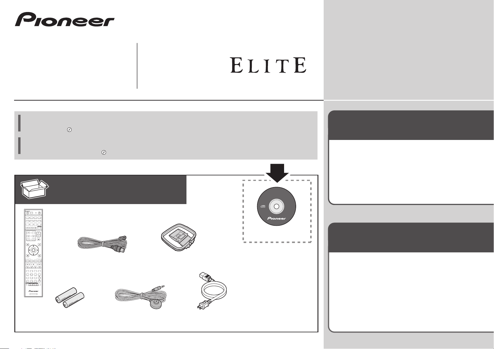
What’s in the box
Contenu du carton d’emballage
ALL ZONE STBY
SOURCE
STANDBY/ON
DISCRETE ON
Remote Control
RCU SETUP
BDR
BD DVDDVR
HDMI
Télécommande
NET
ADPT
CDTV
USB CBL
iPod
SATTUNERMHL
RECEIVER
SELECT
STATUS
INPUT
VOLUME
INPUT
TV CONTROL
VOL
CH
MUTE
VIDEO
AUDIO
PARAMETER
PARAMETER
TOOLS
TOP MENU
MENU
ENTER
HOME
RETURN
MENU
iPod CTRL
FEATURES
P.CTRL+PHASE
ECO
PQLS
MPX
BAND PTY
PRESET TUNE
AUTO/ALC/
+Favorite
STANDARD ADV SURR
DIRECT
AUDIO
13
2
AUTO
S.RTRV
MCACC
CH LEVEL
SIGNAL SEL
DISP
546
DIMMERSLEEP
SPEAKERS
CH
8079
HDMI OUT
D.ACCESS
CLASS
ENTER / CLR
CH
OPTION
ZONE 2 ZONE 3
HD ZONE
Z2 Z3 HDZ
RECEIVER
AAA size IEC R03 dry cell batteries x2
Piles à anode sèche AAA IEC R03 x 2
FM wire antenna
Antenne filaire FM
AM loop antenna
Antenne cadre AM
Setup microphone
Microphone de configuration
Power cord
Cordon d’alimentation
AVNavigator
CD-ROM
Warranty sheet
Feuille de garantie
These quick start guide
Le présent Guide rapide
Safety Brochure
Brochure sur la Sécurité
Register your product at
http://www.pioneerelectronics.com (US)
http://www.pioneerelectronics.ca (Canada)
Protect your new investment
The details of your purchase will be on file for reference in the event of an
insurance claim such as loss or theft.
Receive free tips, updates and service bulletins on
your new product
Improve product development
Your input helps us continue to design products that meet your needs.
Receive a free Pioneer newsletter
Registered customers can opt in to receive a monthly newsletter.
Enregistrez votre produit sur le site Web :
http://www.pioneerelectronics.com (États-Unis)
http://www.pioneerelectronics.ca (Canada)
Protégez votre nouveau matériel
Les renseignements relatifs à votre matériel seront conservés pour
référence en cas de sinistre, tel que la perte ou le vol.
Recevez des conseils, des informations d’entretien
et de mise à jour sur votre nouveau matériel
Contribuez au développement de nos produits
Votre participation nous aide à concevoir des produits qui répondent à
vos besoins.
Recevez gratuitement le bulletin d’informations de
Pioneer
Les clients enregistrés peuvent, s’ils le désirent, recevoir un bulletin
d’informations mensuel.
Page 2
English
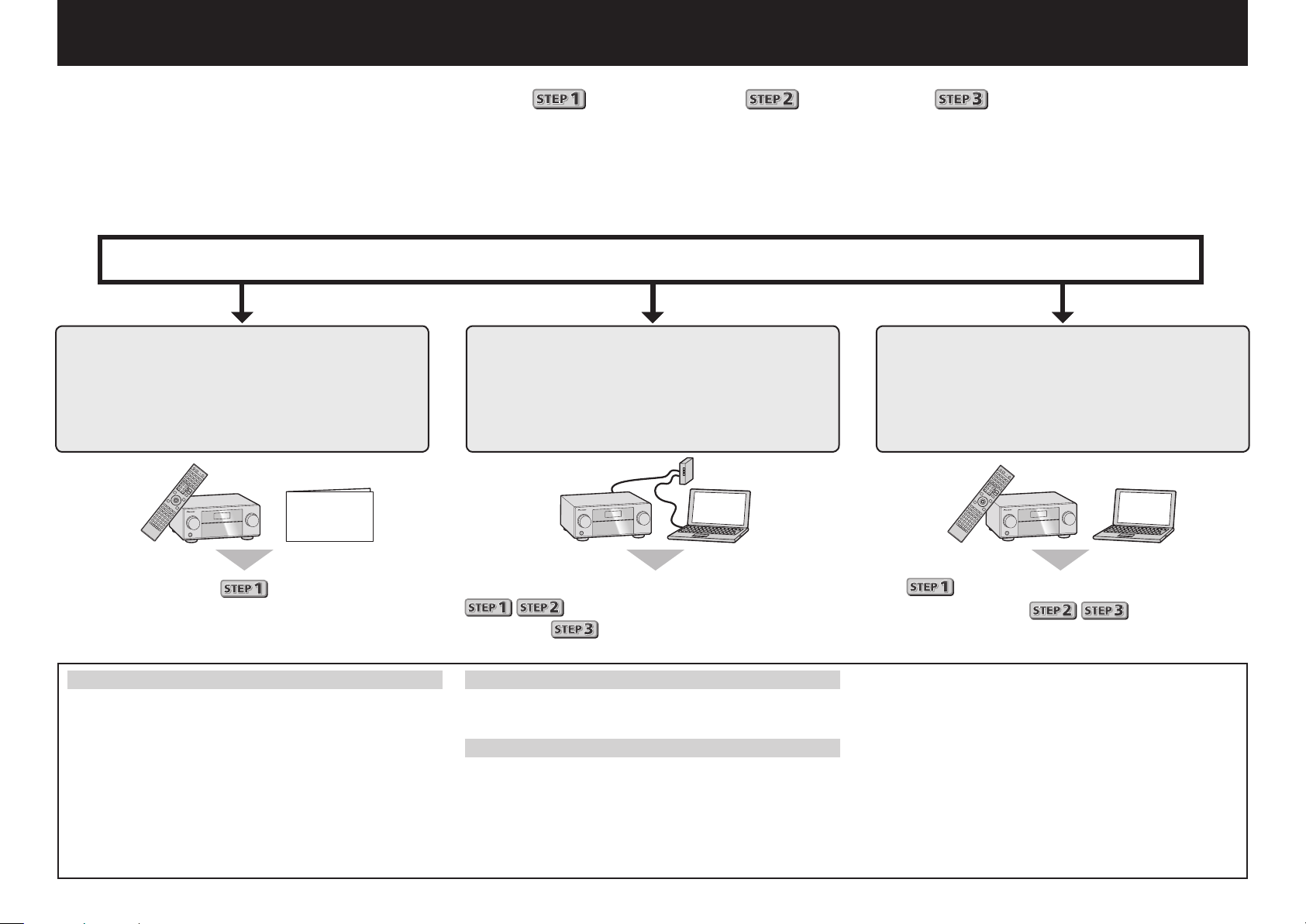
Enjoy easy multichannel playback with this unit in 3 steps:
Connecting up
→
Initial setup
→
Basic playback
Convenient with easy connection and initial setup upon following the instructions displayed on-screen by installing AVNavigator.
•The Mac OS version of AVNavigator can be downloaded from http://www.pioneerelectronics.com.
•The iPad version of AVNavigator can be downloaded from the App Store.
•The provided CD-ROM includes the Windows version of AVNavigator.
Start connecting by choosing one method from among the following in accordance with your play environment.
Connection and initial setup
Connection and initial setup by
referring to this Quick Start Guide
Quick Start
Guide
Connection and initial setup following
the instructions in the
“Wiring Navi” in AVNavigator
(Connection to the network is required
for the initial setup.)
Connect by following the instructions
in the “Wiring Navi” in AVNavigator
(For when the receiver is not to be
connected to a network.)
.
Move on to
Using AVNavigator
AVNavigator for Mac
Download “AVNavigator 2013.pkg” from
1
http://www.pioneerelectronics.com.
Launch “AVNavigator 2013.pkg” from the “Downloads”
2
folder.
Follow the instructions on the screen to install.
3
Launch “AVNavigator 2013”.
4
The file is located in the “Applications” folder just under
the hard disk (Macintosh HD).
2
in this guide.
It is unnecessary to read this guide for explanations;
will be explained in the “Wiring Navi”
and
AVNavigator for iPad
Download AVNavigator from the App Store.
1
Launch AVNavigator.
2
AVNavigator for Windows
Launch the desktop from the start screen (for Windows 8 only).
Load the included CD-ROM into your computer’s CD drive.
1
• The CD-ROM’s top menu screen appears.
• This CD-ROM can be used with Microsoft
XP/Windows Vista
• The supported browser is Microsoft Internet Explorer 8,9 or 10.
in the “Operation Guide”.
®
®
/Windows® 7/Windows® 8.
Windows®
will be conducted in the “Wiring Navi”,
so move on to
in this guide’
after “Wiring Navi” is completed.
Click “AVNavigator” on the “Installing Software” menu.
2
Follow the instructions on the screen to install.
3
Click [AVNavigator] on the desktop to launch AVNavigator.
4
• AVNavigator is launched and Wiring Navi starts up.
• Depending on the network or security settings on the
computer on which AVNavigator is to be installed,
AVNavigator’s functions may not work properly.
Page 3
Connecting up
12 3
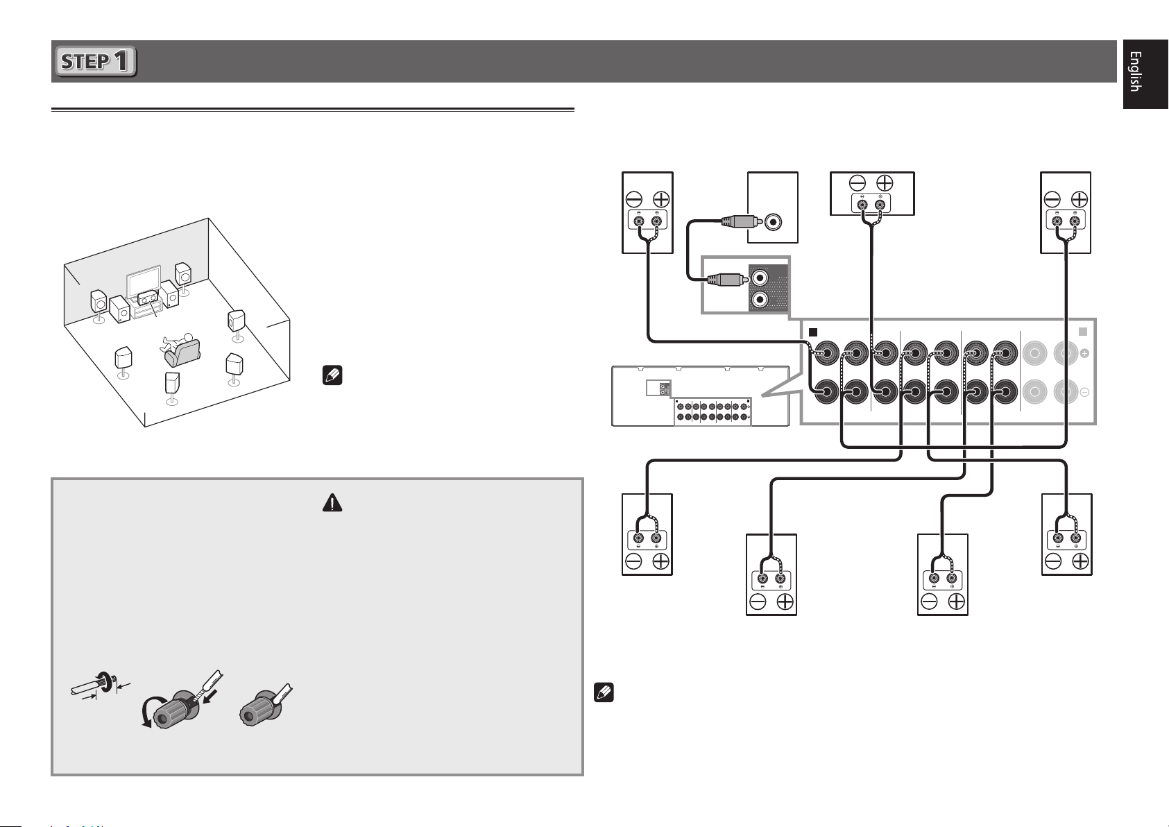
Connecting the speakers
The receiver will work with just two stereo speakers (the front speakers in the diagram) but using
at least five speakers is recommended, and a complete setup is best for surround sound.
To achieve the comfortable surround sound, install your speakers as shown below.
7.2 channel surorund system:
L
– Front Left
C
R
L
SW
SW 2
1
C
SR
SBR
SL
SBL
Connecting the speaker cables
Make sure you connect the speaker on
the right to the right (R) terminal and the
speaker on the left to the left (L) terminal.
Also make sure the positive and negative
+/–
(
) terminals on the receiver match those
on the speakers.
Twist exposed wire strands together.
1
Loosen terminal and insert exposed wire.
2
Tighten terminal.
3
– Center
R
– Front Right
SL
– Surround Left
SR
– Surround Right
SBL
– Surround back Left
SBR
– Surround back Right
SW
– Subwoofer
Note
• There are also other speaker connection
patterns (front height, front wide, etc.).
For details, see page 18 of the operating
instructions.
CAUTION
• Before making or changing connections,
switch off the power and disconnect the
power cord from the AC outlet.
• These speaker terminals carry
HAZARDOUS LIVE
risk of electric shock when connecting
or disconnecting the speaker cables,
disconnect the power cord before
touching any uninsulated parts.
voltage. To prevent the
After installing the speakers, connect them as shown below.
Front Right
(R)
PRE OUT
SUB
WOOFER
1
2
Surround Right
(SR)
Subwoofer
(SW)
LINE LEVEL
INPUT
PRE OUT
SURROUND BACK / ZONE 2
SURROUNDCENTERFRONT
A
(Single
SPEAKERS
)
FRONT HEIGHT / WIDE /
SUB
WOOFER
1
2
A
B
RLRLRLRL
Surround back Right
SBR
(
)
Center
(C)
Surround back Left
SURROUNDCENTERFRONT
SPEAKERS
SBL
(
SURROUND BACK / ZONE 2
)
(
)
Single
FRONT HEIGHT / WIDE /
Front Left
(L)
RLRLRLRL
B
Surround Left
(SL)
10 mm
3
(
/8 in.)
Note
• When only connecting one surround back speaker, connect it to the
(Single)
• This unit supports speakers with a nominal impedance of 6 W to 16 W.
terminals.
SURROUND BACK L
3
Page 4
Connecting up (continued)
ANTENNA
FM UNBAL
75
AM LOOP
ANTENNA
FM UNBAL
75
AM LOOP
21
LAN
(
10/100
)
VENTILATION CAUTION
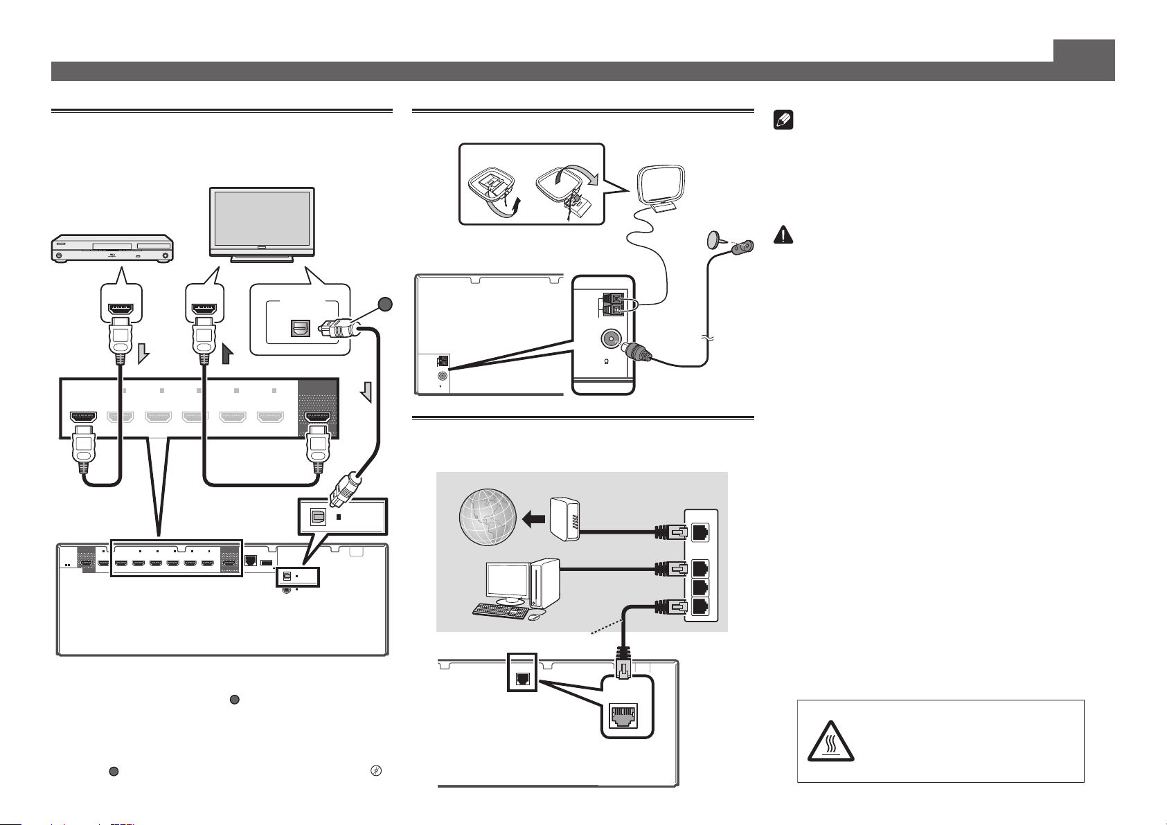
Connecting a TV and playback
components
HDMI/DVI-compatible
Blu-ray DIsc player
BD IN
HDMI
(HDZONE)
ASSIGNABLE
-
1 7
• If the TV does not support the HDMI Audio Return Channel
function, optical digital cable (
listen to the TV sound over the receiver.
• If the TV supports the HDMI Audio Return Channel function,
the sound of the TV is input to the receiver via the HDMI
terminal, so there is no need to connect an optical digital
cable (
HDMI Setup
4
“
2
IN
(
SAT/CBL
OUT 2
BD IN
1
IN
(
)
DVD
SELECTABLE
A
). In this case, set
)
2
IN
(
SAT/CBL
3
IN
(
)
DVR/BDR
IN3IN4IN6IN
)
(
)
DVR/BDR
”
HDMI/DVI-compatible TV
HDMI INHDMI OUT
4
IN
6
IN
7
OUT 1
(
)
CONTROL
A
) connection is required to
ARC
at
DIGITAL OUT
7
IN
)
LAN
(10/100
DC OUTPUT
for WIRELESS LAN
(
OUTPUT 5 V
)
0.6 A MAX
HDMI Setup
OPTICAL
(
(TV)
1
IN
(
1
IN
DVD
CONTROL
OPTICAL
ASSIGNABLE
COAXIAL
ASSIGNABLE
OUT 1
)
IN
)
to ON l
(TV)
1
OPTICAL
ASSIGNABLE
Connecting antennas
AM loop antenna
A
FM wire antenna
Connecting to the network through
LAN interface
Internet
Computer
LAN cable (sold separately)
Modem
Router
)
LAN
(10/100
WAN
Note
• Refer to the operating instructions in the included CD-
ROM if you wish to connect a TV or playback component
in a method other than an HDMI connection.
• Refer to the operating instructions in the included CD-
ROM for other device connections.
CAUTION
• Handle the power cord by the plug part. Do not pull out
the plug by tugging the cord, and never touch the power
cord when your hands are wet, as this could cause a short
circuit or electric shock. Do not place the unit, a piece of
furniture, or other object on the power cord or pinch the
cord in any other way. Never make a knot in the cord or tie
it with other cables. The power cords should be routed so
that they are not likely to be stepped on. A damaged power
cord can cause a fire or give you an electric shock. Check
the power cord once in a while. If you find it damaged,
ask your nearest Pioneer authorized independent service
company for a replacement.
When installing this unit, make sure to leave space
around the unit for ventilation to improve heat radiation
(at least 40 cm at top, 10 cm at rear, and 20 cm at each
side).
LAN
1
2
3
WARNING
Slots and openings in the cabinet are provided for
ventilation to ensure reliable operation of the product,
and to protect it from overheating. To prevent fire
hazard, the openings should never be blocked or
covered with items (such as newspapers, table-cloths,
curtains) or by operating the equipment on thick carpet
or a bed.
D3-4-2-1-7b*_A1_En
CAUTION:
HOT SURFACE. DO NOT TOUCH.
The top surface over the internal
heatsink may become hot when
operating this product continuously.
Page 5
Initial Setup
MASTER
VOLUME
STANDBY/ON
INPUT
SELECTOR
iPod iPhone iPad
DIRECT
CONTROLECO
ADVANCED
SURROUND
STANDARD
SURROUND
AUTO SURR/ALC/
STREAM DIRECT
PHONES
SPEAKERS CONTROL – MULTI-ZONE – ON / OFF BAND TUNER EDIT TUNE PRESET ENTER
iPod iPhone iPadHDMI
ADVANCED
MCACC
FL OFF
MCACC
SETUP MIC
with USB
5V 2.1 A
HDMI 5 INPUT/
MHL (5V 0.9 A)
MCACC
SETUP
MIC
RECEIVER
1. Advanced MCACC
2. MCACC Data Check
3. Data Management
4. System Setup
5. Network Information
6. Operation Mode Setup
Exit Return
HOME MENU
A/V RECEIVER
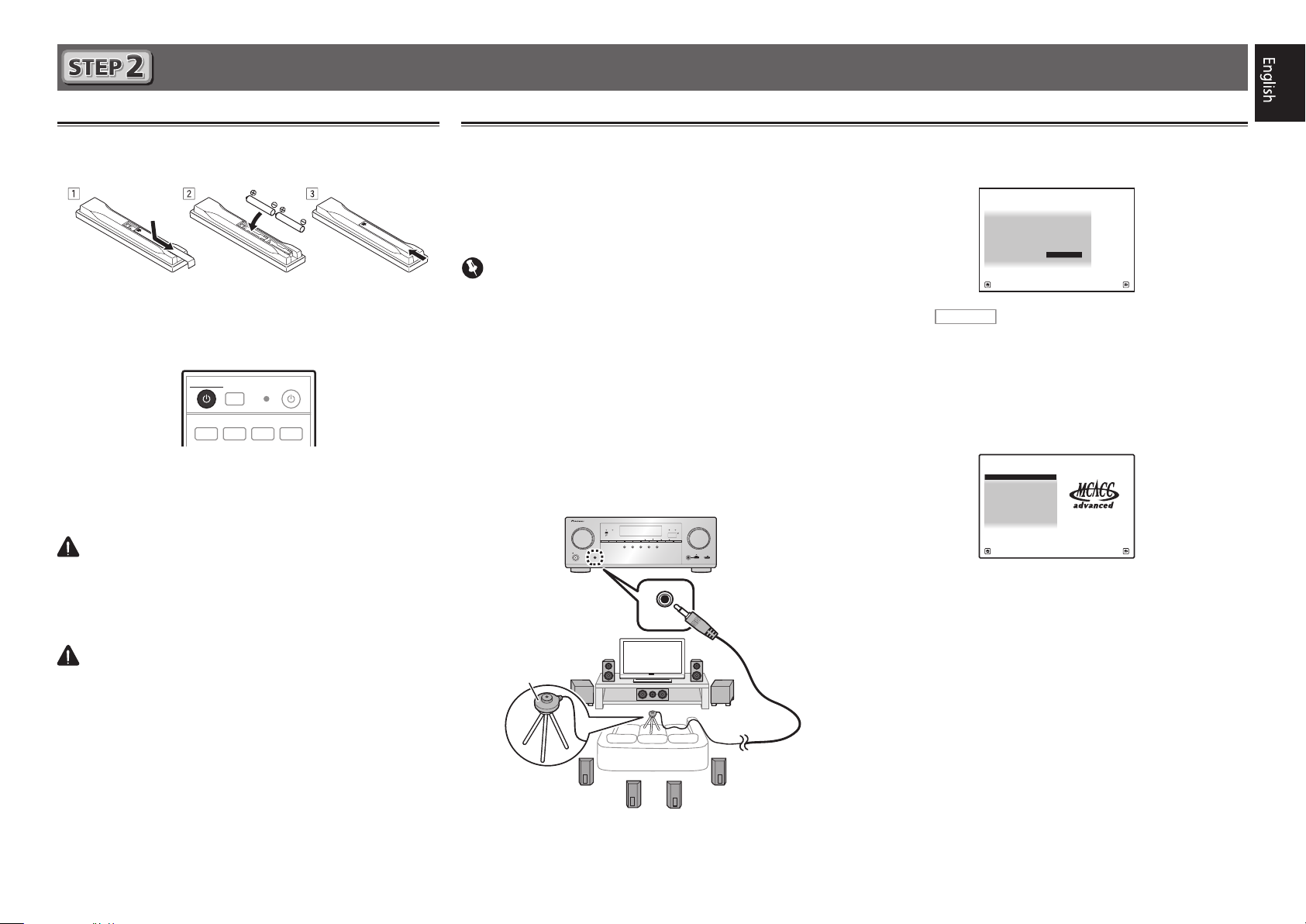
Before you start
Put the batteries in the remote control.
1
The batteries included with the unit are to check initial
operations; they may not last over a long period. We
recommend using alkaline batteries that have a longer life.
Switch on the receiver and your TV.
2
ALL ZONE STBY
STANDBY/ON
DISCRETE ON
RCU SETUP
BD DVDDVR HDMI
Switch the TV input so that it connects to the
3
receiver.
Turn the subwoofer on and turn up the volume.
4
WARNING
• Do not use or store batteries in direct sunlight or other
excessively hot place, such as inside a car or near a heater.
This can cause batteries to leak, overheat, explode or catch
fire. It can also reduce the life or performance of batteries.
CAUTION
• When inserting the batteries, make sure not to damage
the springs on the battery’s (–) terminals. This can cause
batteries to leak or overheat.
• When disposing of used batteries, please comply with
governmental regulations or environmental public institution’s rules that apply in your country/area.
SOURCE
BDR
Automatically setting up for surround sound (MCACC)
The Auto Multi-Channel Acoustic Calibration (MCACC) setup
uses the supplied setup microphone to measure and analyze
the test tone that is outputted by the speakers. This setup
enables automatic high precision measuring and settings;
utilizing it will create an optimum user listening environment.
Important
• Measure in a quiet environment.
• If you have a tripod, use it to place the microphone so
that it’s about ear level at your normal listening position.
Otherwise, place the microphone at ear level using a table
or a chair.
• Accurate measurements may not be possible if there are
obstacles between the speakers and the listening position
(microphone).
• When measuring, step away from the listening position,
and operate using the remote control from the external
side of all the speakers.
Connect the supplied setup microphone.
1
Microphone
Tripod
2
3
4
Full Auto MCACC
The
Press
screen appears on your TV.
1a.Full Auto MCACC
Speaker System : Normal(SB/FH
EQ Type : SYMMETRY
MCACC : M1.MEMORY 1
THX Speaker : NO
START
Exit Return
on the remote control, then
press the ENTER button.
• Automatic measuring will start.
• Measuring will take about 3 to 12 minutes.
Follow the instructions on-screen.
• Automatic setting is complete when the Home Menu
screen appears.
Reverse Phase
• If
is displayed, the speaker’s wiring (+ and –)
may be inverted. Check the speaker connections.
Even if the connections are correct,
displayed, depending on the speakers and the surrounding
environment. This does not affect measurements, however,
so select
• If
Go Next
ERR
is displayed, check that speaker is properly
.
connected.
Make sure the setup microphone is
disconnected.
A/V RECEIVER
)
Reverse Phase
may be
5
Page 6

Basic playback
RECEIVER
D.ACCESS
CH LEVEL
DIMMER SLEEP
SIGNAL SEL
SPEAKERS
MPX
PRESETTUNE
BAND PTY
iPod CTRL
HOME
MENU
CH
TV CONTROL
INPUT
INPUT
SELECT
iPod
USBCBL
STATUS
SAT TUNER
ZONE 2 ZONE 3
HD ZONE
ADPT
CDTV
RCU SETUP
SOURCE
STANDBY/ON
BDR
BD DVDDVR
NET
HDMI
RECEIVER
MUTE
VOLUME
VOL
TOP MENU
VIDEO
PARAMETER
AUDIO
PARAMETER
ENTER
RETURN
CLASS
ENTER / CLR
CH
CH
546
8
0
79
FEATURES
TOOLS
MENU
ALL ZONE STBY
DISCRETE ON
+Favorite
Z2 Z3 HDZ
P.CTRL
+
PHASE
HDMI OUT
MCACC
AUTO/ALC/
DIRECT
AUTO
S.RTRV
STANDARDADV SURR
ECO
PQLS
OPTION
AUDIO
DISP
MHL
213
2
4
6
3
Switch on the playback component.
Multichannel playback
1
E.g.) Turn the Blu-ray Disc player connected to the
BD IN
terminal on.
Switch the input of the receiver.
2
E.g.) Press BD to select the BD input.
RECEIVER
Press
3
Press AUTO/ALC/DIRECT to select ’AUTO
4
SURROUND’.
Also press
playback. Select your preferred listening mode.
Start the playback component’s playback.
5
E.g.) Start playback of the Blu-ray Disc player.
Use VOLUME +/– to adjust the volume level.
6
Sound can be switched off by pressing
Note
• Switch to one of the underlined devices to use the remote
control to operate that device. To operate the receiver,
first press
operate.
• The receiver’s remote control can be used to operate
not only the receiver but also a variety of other devices,
including an iPod/USB device, a Blu-ray Disc player, a TV,
etc.
E.g.) Playing a Blu-ray Disc player
BD
to the receiver operation mode.
STANDARD
RECEIVER
, then press the appropriate button to
ADV SURR
or
for multichannel
MUTE
button.
HDMI
Listening to the radio
Press TUNER to select the tuner.
1
If necessary, press
Press TUNE +/– to tune to a station.
2
• Press and hold
will start searching for the next station.
• If you’re listening to an FM station but the reception is
weak, press
to the mono reception mode.
Saving station presets
If you often listen to a particular radio station, it’s convenient to
have the receiver store the frequency for easy recall whenever
you want to listen to that station.
Press TOOLS while receiving a signal from the
1
station you want to store.
The preset number is blinking.
Press PRESET +/– to select the station preset
2
you want, then press ENTER.
The preset number stop blinking and the receiver stores
the station.
Listening to station presets
You will need to have some presets stored to do this.
Press PRESET +/– to select the station preset
you want.
BAND
to change the band (FM or AM).
TUNE +/–
MPX
to select FM MONO and set the receiver
for about a second. The receiver
6
Page 7

Basic playback (continued)
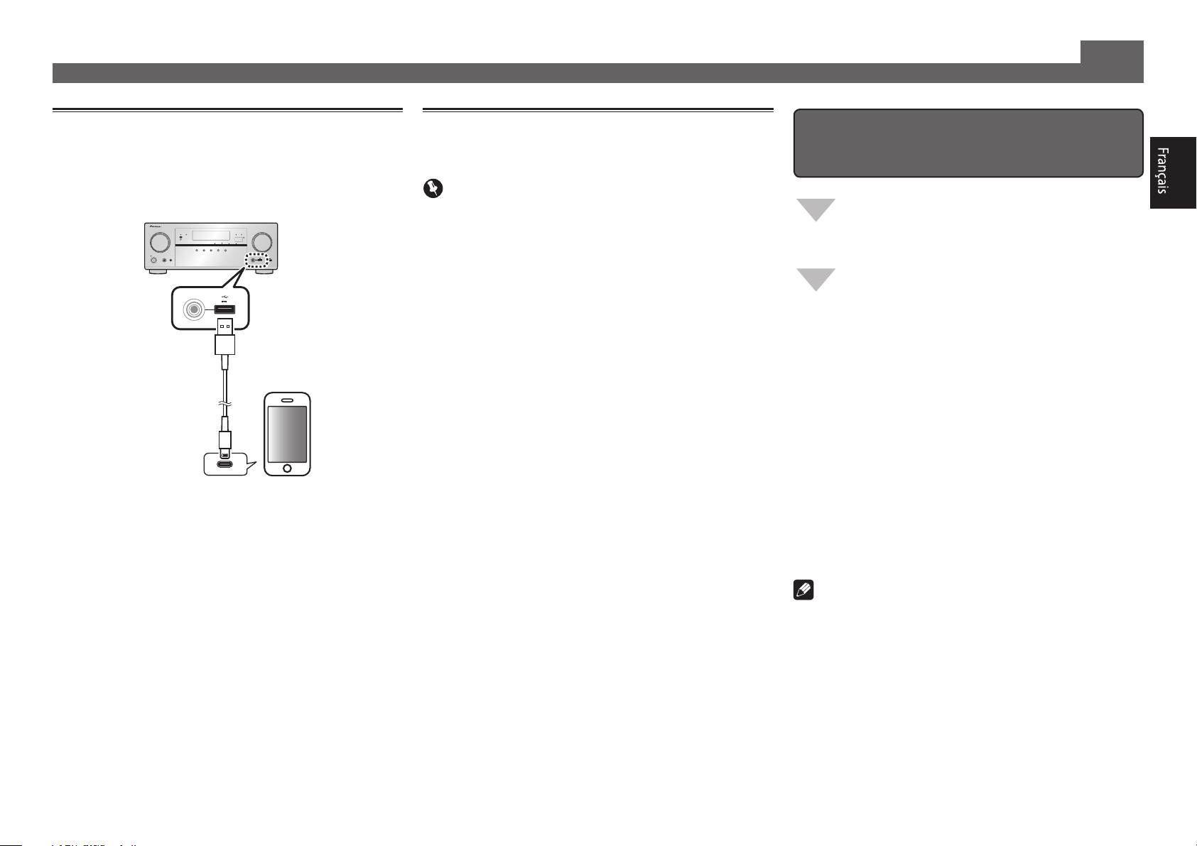
Playing an iPod
• About one minute is required between turning the power
on and completion of startup.
Connect your iPod.
1
An iPod/iPhone/iPad can be connected to the receiver.
ADVANCED
MCACC
FL OFF
SPEAKERS CONTROL – MULTI-ZONE – ON / OFFBAND TUNER EDIT TUNE PRESET ENTER
AUTO SURR/ALC/
STANDBY/ON
MCACC
PHONES
SETUP MIC
with USB
USB cable
STREAM DIRECT
INPUT
SELECTOR
included with the iPod
Press iPod USB to select the iPod/USB input.
2
When the display shows the names of folders and files,
you’re ready to play music from the iPod.
3
Use
to select a category, then press
/
ENTER to browse that category.
•Toreturntothepreviouslevelanytime,press
4
Use
to browse the selected category (e.g.,
/
albums).
•Use
Continue browsing until you arrive at what
5
to move to previous/next levels.
/l
you want to play, then press to start
playback.
iPod iPhone iPadHDMI
iPod iPhone iPad
ADVANCED
STANDARD
DIRECT
CONTROLECO
SURROUND
SURROUND
5 V
2.1
MASTER
VOLUME
with USB
HDMI 5 INPUT/
MHL (5V 0.9 A)
5V 2.1 A
A
iPod/iPhone/iPad
RETURN
Listening to Internet radio stations
• About one minute is required between turning the power
on and completion of startup.
Important
• When using a broadband Internet connection, a contract
with an Internet service provider is required. For more
details, contact your nearest Internet service provider.
• To listen to Internet radio stations, you must have high-
speed broadband Internet access. With a 56 K or ISDN
modem, you may not enjoy the full benefits of Internet
radio.
• Access to content provided by third parties requires a
high speed internet connection and may also require
account registration and a paid subscription. Third
party content services may be changed, suspended,
interrupted, or discontinued at any time without notice,
and Pioneer disclaims any liability in connection with such
occurrences. Pioneer does not represent or warrant that
content services will continue to be provided or available
for a particular period of time, and any such warranty,
express or implied, is disclaimed.
Press NET repeatedly to select the INTERNET
1
RADIO input.
It may take several seconds for this receiver to access the
network.
Use
2
.
play back, and then press ENTER.
to select the Internet radio station to
/
To enjoy the many functions of the
unit to the fullest extent
Install the AVNavigator into your computer, and
use the "Interactive Manual" and “Operation
Guide”.
Load the CD-ROM into your computer and
download the PDF manual from the menu screen
to read.
Functions
Playing a USB device
#
Bluetooth ADAPTER for Wireless Enjoyment of Music
#
Playback with NETWORK feature
#
Setting the Audio options
#
Setting the Video options
#
Using the MULTI-ZONE controls
#
FAQ
Glossary
Features index
Note
• This unit supports AirPlay. For details, see page 53 of the
operating instructions and the Apple website (http://www.
apple.com).
• This unit’s software can be updated (page 89 of the
operating instructions). With Mac OS, it can be updated
using Safari (page 91 of the operating instructions).
© 2013 PIONEER CORPORATION.
All rights reserved.
7
Page 8

Français
Profitez de la lecture multicanaux sur cet appareil en 3 points seulement :
Raccordement
→
Conguration initiale
→
Lecture de base
En installant l’AVNavigator vous pourrez faire facilement les raccordements et la configuration initiale en suivant les instructions qui apparaissent sur l’écran.
•La version Mac OS de l’AVNavigator peut être téléchargée de http://www.pioneerelectronics.com.
•La version iPad de l’AVNavigator peut être téléchargée d’App Store.
•Le CD-ROM fourni contient la version Windows de l’AVNavigator.
Choisissez tout d’abord une méthode de raccordement selon les enceintes utilisées.
Raccordement et conguration initiale
Raccordement et conguration initiale
en suivant le guide rapide
Guide
rapide
Raccordement et conguration initiale
en se référant aux instructions dans
“Wiring Navi” de l’AVNavigator
(Une connexion au réseau est nécessaire
pour la conguration initiale.)
Faites les raccordements en suivant les
instructions dans
“Wiring Navi” de l’AVNavigator
(Si le récepteur n’est pas connecté à un réseau.)
.
Passez à
Utilisation de l’AVNavigator
AVNavigator pour Mac
Téléchargez “AVNavigator 2013.pkg” de
1
http://www.pioneerelectronics.com.
Lancez “AVNavigator 2013.pkg” à partir du dossier
2
“Downloads”.
Suivez les instructions apparaissant à l’écran pour
3
installer l’application.
Lancez “AVNavigator 2013”.
4
Le fichier se trouve dans le dossier “Applications” juste en
dessous du disque dur (Macintosh HD).
2
dans ce guide.
Il est inutile de lire les explications dans ce guide ;
sont expliqués dans “Wiring Navi” et
dans le “Guide d’utilisation”.
AVNavigator pour iPad
Téléchargez l’AVNavigator de l’App Store.
1
Lancez l’AVNavigator.
2
AVNavigator pour Windows
Lancez le bureau depuis l’écran de démarrage (Windows 8
seulement).
Posez le CD-ROM inclus dans le lecteur CD de votre ordinateur.
1
• La première page du menu du CD-ROM apparaît.
• Ce CD-ROM peut être utilisé avec Microsoft
XP/Windows Vista
• Le navigateur pris en charge est Microsoft Internet Explorer
8,9 ou 10.
®
/Windows® 7/Windows® 8.
®
Windows®
est expliqué dans “Wiring Navi”, vous
pouvez passer à
de ce guide
lorsque “Wiring Navi” est terminé.
Cliquez sur “AVNavigator” dans le menu “Installing Software”.
2
Suivez les instructions apparaissant à l’écran pour installer
3
l’application.
Cliquez sur [AVNavigator] sur le bureau pour lancer
4
l’AVNavigator.
• L’AVNavigator s’ouvre et Wiring Navi démarre.
• Selon les réglages réseau ou sécurité de l’ordinateur
sur lequel l’AVNavigator est installé, les fonctions de
l’AVNavigator peuvent ne pas agir correctement.
Page 9

Raccordement
12 3
Raccordement des enceintes
Le récepteur fonctionne avec deux enceintes stéréo seulement (enceintes avant sur le schéma)
mais il est conseillé d’utiliser au moins cinq enceintes, et avec une configuration complète le
son surround sera bien meilleur.
Pour obtenir le son surround le plus agréable, installez vos enceintes comme illustré ci-dessous.
Système surround à 7.2 canaux :
L
SW 2
Raccordement des câbles d’enceintes
Veillez à bien raccorder l’enceinte de droite
à la borne droite (R) et l’enceinte de gauche
à la borne de gauche (L). Assurez-vous aussi
que les bornes positives et négatives (
sur le récepteur correspondent à celles des
enceintes.
Torsadez les ls ensemble.
1
Dévissez la borne et insérez la partie
2
dénudée des ls.
Serrez la borne.
3
10 mm
C
SL
R
SW
1
SBL
SR
SBR
+/–
Après avoir installé les enceintes, raccordez-les de la façon ci-dessous.
Gauche
FRONT HEIGHT / WIDE /
)
RLRLRLRL
Avant
(L)
B
L
– Avant Gauche
C
– Centre
R
– Avant Droite
SL
– Surround Gauche
SR
– Surround Droite
SBL
– Surround arrière Gauche
SBR
– Surround arrière Droite
SW
– Caisson de grave
Remarque
• Il existe aussi d’autres façons de connecter
les enceintes (avant haute, avant large,
Avant Droite
(R)
PRE OUT
SUB
WOOFER
1
2
Caisson de
grave
(SW)
LINE LEVEL
INPUT
PRE OUT
SURROUND BACK / ZONE 2
SURROUNDCENTERFRONT
A
(Single
SPEAKERS
)
FRONT HEIGHT / WIDE /
SUB
WOOFER
1
2
A
B
RLRLRLRL
Centre
(C)
SURROUNDCENTERFRONT
SPEAKERS
SURROUND BACK / ZONE 2
(
Single
etc.). Pour le détail, reportez-vous à la page
17 du mode d’emploi.
ATTENTION
• Avant de réaliser ou de modifier des
liaisons, éteignez les appareils et
débranchez le cordon d’alimentation de
)
la prise électrique.
• Ces bornes d’enceintes sont soumises à
une tension
DANGEREUSE
. Pour éviter
tout risque de décharge électrique lors
du branchement ou débranchement des
câbles d’enceintes, débranchez le cordon
d’alimentation avant de toucher les
parties non isolées.
Surround Droite
Surround Gauche
(SR)
Surround arrière Droite
SBR
(
)
Surround arrière Gauche
SBL
(
)
Remarque
• Si vous raccordez une seule enceinte surround arrière, raccordez-la aux bornes
BACK L (Single)
• Cet appareil accepte les enceintes ayant une impédance nominale de 6 W à 16 W.
.
(SL)
SURROUND
3
Page 10

Raccordement (suite)
ANTENNA
FM UNBAL
75
AM LOOP
LAN
(
10/100
)
A
PRÉCAUTION DE VENTILATION
Raccordement d’un téléviseur et de
lecteurs
Lecteur de disque Blu-ray
compatible HDMI/DVI
BD IN
HDMI
(HDZONE)
ASSIGNABLE
-
1 7
• Si votre téléviseur ne prend pas en charge la fonction HDMI
de canal de retour audio, vous devrez effectuer une liaison par
câble numérique optique (
via le récepteur.
• Si votre téléviseur prend en charge la fonction HDMI de canal
de retour audio, le son du téléviseur est transmis au récepteur
par la prise HDMI et il est inutile de raccorder un câble
numérique optique (
4
Setup
OUT 2
SELECTABLE
2
IN
(
SAT/CBL
BD IN
1
IN
(
)
DVD
sur ON
IN
)
(
DVR/BDR
2
IN
IN3IN4IN6IN
(
)
(
SAT/CBL
DVR/BDR
l
3
)
)
A
“Réglage de l’HDMI”
Téléviseur compatible
HDMI/DVI
HDMI INHDMI OUT
4
IN
6
IN
7
OUT 1
(
)
CONTROL
DIGITAL OUT
OPTICAL
7
IN
)
LAN
(10/100
DC OUTPUT
for WIRELESS LAN
(
OUTPUT 5 V
0.6 A MAX
OUT 1
(
CONTROL
)
OPTICAL
(TV)
1
IN
ASSIGNABLE
COAXIAL
(
)
1
IN
DVD
ASSIGNABLE
) pour écouter le son du téléviseur
). Dans ce cas, réglez
ARC
)
(TV)
1
IN
dans
OPTICAL
ASSIGNABLE
HDMI
Raccordement des antennes
21
A
AM LOOP
FM UNBAL
75
ANTENNA
Antenne cadre AM
Antenne fil FM
Raccordement au réseau par l’interface LAN
Internet
Ordinateur
Câble LAN (vendu séparément)
Modem
)
LAN
(10/100
Routeur
WAN
LAN
Remarque
• Reportez-vous aux instructions sur le CD-ROM fourni si
vous voulez raccorder un téléviseur ou un lecteur d’une
autre façon que par une liaison HDMI.
• Reportez-vous aux instructions sur le CD-ROM fourni pour
d’autres liaisons.
ATTENTION
• Saisissez le cordon d’alimentation par la prise. Ne
débranchez jamais la fiche en tirant sur le cordon et ne
touchez jamais le cordon d’alimentation lorsque vous avez
les mains mouillées, car cela pourrait causer un courtcircuit ou une électrocution. Ne placez pas l’appareil, un
meuble ou tout autre objet sur le cordon d’alimentation et
ne coincez pas le cordon. Ne faites jamais de nœud sur
le cordon, et ne le nouez pas avec d’autres câbles. Les
cordons d’alimentation doivent être placés de telle sorte
que l’on ne risque pas de marcher dessus. Un cordon
d’alimentation endommagé peut entraîner un incendie
ou une électrocution. Vérifiez le cordon d’alimentation
de temps en temps. Si vous le trouvez abîmé, demandez
à votre service après-vente Pioneer le plus proche de le
remplacer.
Lors de l’installation de l’appareil, veillez à laisser un
espace suffisant autour de ses parois de manière à
améliorer la dissipation de chaleur (au moins 40 cm sur
le dessus, 10 cm à l’arrière et 20 cm de chaque côté).
1
2
3
AVERTISSEMENT
Les fentes et ouvertures du coffret sont prévues pour la
ventilation, pour assurer un fonctionnement stable de
l’appareil et pour éviter sa surchauffe. Pour éviter les
risques d’incendie, ne bouchez jamais les ouvertures et
ne les recouvrez pas d’objets, tels que journaux, nappes
ou rideaux, et n’utilisez pas l’appareil posé sur un tapis
épais ou un lit.
D3-4-2-1-7b*_A1_Fr
ATTENTION:
SURFACE CHAUDE. NE PAS TOUCHER.
La surface supérieure du dissipateur de
chaleur interne peut devenir très chaude
lorsque ce produit fonctionne en
permanence.
Page 11

Conguration initiale
RECEIVER
1. Advanced MCACC
2. MCACC Data Check
3. Data Management
4. System Setup
5. Network Information
6. Operation Mode Setup
Exit Return
HOME MENU
A/V RECEIVER
Avant de commencer
Insérez des piles dans la télécommande.
1
Les piles fournies avec l’appareil sont destinées à vérifier
le bon fonctionnement de l’appareil et risquent de ne pas
durer longtemps. Nous vous conseillons d’utiliser des
piles alcalines dont l’autonomie est plus longue.
Allumez le récepteur et votre téléviseur.
2
Sélectionnez l’entrée du téléviseur pour qu’il
3
se connecte au récepteur.
Allumez le caisson de grave et augmentez le
4
volume.
AVERTISSEMENT
• N’utilisez pas ou ne rangez pas les piles en plein soleil
ou à un endroit très chaud, comme dans une voiture ou
près d’un appareil de chauffage. Les piles pourraient fuir,
surchauffer, exploser ou prendre feu. Cela peut aussi
réduire leur durée de vie et leurs performances.
ATTENTION
• Lors de l’insertion des piles, veillez à ne pas endommager
les ressorts au niveau des bornes (–) des piles. Les piles
pourraient fuir ou surchauffer.
• Pour la mise au rebut des piles/batteries usées, veuillez
vous conformer aux réglementations gouvernementales
ou environnementales en vigueur dans votre pays/région.
ALL ZONE STBY
STANDBY/ON
DISCRETE ON
RCU SETUP
BD DVDDVR HDMI
BDR
SOURCE
Conguration automatique du son surround (MCACC)
Lors du calibrage acoustique multicanaux automatique
(MCACC), le microphone de configuration fourni est utilisé
pour mesurer et analyser la tonalité de test émise par les
enceintes. Cette configuration permet d’effectuer des mesures
et réglages extrêmement précis et de créer un environnement
d’écoute optimal pour chaque situation.
Important
• Les mesures doivent être faites dans un environnement
calme.
• Positionnez le microphone sur un trépied (si vous en avez
un) pour qu’il se trouve à hauteur d’oreilles en position
d’écoute normale. Sinon, positionnez le microphone à
hauteur d’oreille en le posant sur une table ou sur une
chaise.
• Il ne sera pas possible d’obtenir des mesures précises s’il
y a des obstacles entre les enceintes et la position d’écoute
(microphone).
• Pendant les mesures éloignez-vous de la position d’écoute
et actionnez la télécommande loin de toutes les enceintes.
Raccordez le microphone de conguration
1
fourni.
ADVANCED
MCACC
Microphone
Trépied
INPUT
SELECTOR
STANDBY/ON
MCACC
PHONES
SETUP MIC
FL OFF
SPEAKERS CONTROL – MULTI-ZONE – ON / OFF BAND TUNER EDIT TUNE PRESET ENTER
AUTO SURR/ALC/
STREAM DIRECT
iPod iPhone iPadHDMI
iPod iPhone iPad
ADVANCED
STANDARD
DIRECT
CONTROLECO
SURROUND
SURROUND
MCACC
SETUP
MASTER
VOLUME
with USB
HDMI 5 INPUT/
MHL (5V 0.9 A)
5V 2.1 A
MIC
L’écran
Appuyez sur
2
puis appuyez sur la touche ENTER.
• La mesure automatique commence.
• La mesure dure de 3 à 12 minutes.
Suivez les instructions afchées à l’écran.
3
• Le réglage automatique est terminé lorsque la page Home
Menu apparaît.
• Si
(+ et –) ont peut-être été inversés. Vérifiez les liaisons des
enceintes.
Même si les liaisons sont correctes,
s’afficher, selon les enceintes et l’environnement surround. Ceci n’a cependant aucun effet sur les mesures, et
vous pouvez sélectionner
• Si
Assurez-vous de débrancher le microphone de
4
conguration.
Full Auto MCACC
1a.Full Auto MCACC
Speaker System : Normal(SB/FH
EQ Type : SYMMETRY
MCACC : M1.MEMORY 1
THX Speaker : NO
START
Exit Return
Reverse Phase
ERR
s’affiche, vérifiez si l’enceinte est bien raccordée.
s’affiche, les fils du cordon d’enceinte
apparaît sur votre téléviseur.
A/V RECEIVER
)
de la télécommande,
Reverse Phase
Go Next
.
peut
5
Page 12

Lecture de base
Lecture multicanaux
ALL ZONE STBY
STANDBY/ON
DISCRETE ON
RCU SETUP
BD DVDDVR
2
4
CDTV
USBCBL
SAT TUNER
iPod
INPUT
SELECT
TV CONTROL
CH
AUDIO
PARAMETER
TOP MENU
HOME
MENU
iPod CTRL
P.CTRL
PHASE
MPX
PRESETTUNE
AUTO/ALC/
STANDARDADV SURR
DIRECT
MCACC
SIGNAL SEL
DIMMER SLEEP
SPEAKERS
79
HDMI OUT
D.ACCESS
ZONE 2 ZONE 3
Z2 Z3 HDZ
SOURCE
BDR
NET
MHL
STATUS
VOLUME
INPUT
VOL
MUTE
PARAMETER
ENTER
FEATURES
+
PQLS
BAND PTY
+Favorite
213
CH LEVEL
546
8
CLASS
ENTER / CLR
0
HD ZONE
HDMI
ADPT
RECEIVER
VIDEO
TOOLS
MENU
RETURN
ECO
AUDIO
AUTO
S.RTRV
DISP
CH
CH
OPTION
Allumez le lecteur.
1
Ex.) Allumez le lecteur de disque Blu-ray raccordé à la
HDMI BD IN
prise
Sélectionnez l’entrée du récepteur.
2
Ex.) Appuyez sur BD pour sélectionner l’entrée BD.
Appuyez sur
3
mode de fonctionnement du récepteur.
3
6
Appuyez sur AUTO/ALC/DIRECT pour
4
sélectionner ‘AUTO SURROUND’.
Appuyez aussi sur
lecture multicanaux. Sélectionnez votre mode d’écoute
préférée.
Démarrez la lecture sur le lecteur.
5
Ex.) Démarrez la lecture sur le lecteur de disque Blu-ray.
.
RECEIVER
STANDARD
pour sélectionner le
ADV SURR
ou
pour la
Écoute de la radio
Appuyez sur TUNER pour sélectionner le tuner.
1
Si nécessaire, appuyez sur
(FM ou AM).
Appuyez sur TUNE +/– pour accorder une
2
station.
• Appuyez sur
enfoncée. Le récepteur recherche la station suivante.
• Si vous écoutez une station FM mais que la réception est
faible, appuyez sur
réglez le récepteur sur le mode de réception mono.
TUNE +/–
MPX
Sauvegarde des stations préréglées
Si vous écoutez souvent une station radio précise, il est
intéressant d’en mémoriser la fréquence pour faire l’accord
BAND
pour changer de bande
et maintenez une seconde
pour sélectionner FM MONO et
rapidement sur cette station lorsque vous souhaitez l’écouter.
Utilisez VOLUME +/– pour régler le volume.
6
Le son peut être coupé par la touche
Remarque
• Basculez sur un des appareils soulignés pour agir des-
sus depuis la télécommande. Pour agir sur le récepteur,
appuyez d’abord sur
appropriée.
• La télécommande du récepteur peut être utilisée pour agir
non seulement sur le récepteur mais aussi sur d’autres
dispositifs, comme un appareil iPod/USB, un lecteur de
disque Blu-ray, un téléviseur, etc.
Ex.) Lecture d’un lecteur de disque Blu-ray
BD
RECEIVER
, puis appuyez sur la touche
MUTE
.
Appuyez sur TOOLS pendant la réception
1
du signal de la station que vous voulez
sauvegarder.
Le numéro de préréglage clignote.
Appuyez sur PRESET +/– pour sélectionner le
2
numéro de préréglage souhaité, puis appuyez
sur ENTER.
Le numéro de préréglage cesse de clignoter et la station
est sauvegardée.
Écouter des stations préréglées
Pour ce faire, vous devez avoir préréglé des stations.
Appuyez sur PRESET +/– pour sélectionner la
station préréglée de votre choix.
RECEIVER
6
Page 13
Lecture de base (suite)
Lecture d’un iPod
• Environ une minute est nécessaire entre la mise sous
tension et la fin de la phase de démarrage.
Raccordez votre iPod.
1
Vous pouvez raccorder un iPod/iPhone/iPad au récepteur.
ADVANCED
MCACC
FL OFF
SPEAKERS CONTROL – MULTI-ZONE – ON / OFFBAND TUNER EDIT TUNE PRESET ENTER
AUTO SURR/ALC/
STANDBY/ON
MCACC
PHONES
SETUP MIC
with USB
Câble USB
STREAM DIRECT
INPUT
SELECTOR
fourni avec l’iPod
Appuyez sur iPod USB pour sélectionner
2
l’entrée iPod/USB.
Lorsque les noms de dossiers et de fichiers apparaissent
sur l’afficheur, vous pouvez écouter la musique enregistrée
sur l’iPod.
3
Utilisez
pour sélectionner une catégorie,
/
puis appuyez sur ENTER pour naviguer dans
cette catégorie.
•Pourreveniràtoutmomentauniveauprécédent,
RETURN
pour naviguer dans la catégorie
/
4
appuyez sur
Utilisez
sélectionnée (par exemple, albums).
•Utilisez
Poursuivez votre navigation jusqu’à atteindre
5
pour passer au niveau précédent/suivant.
/l
les éléments que vous souhaitez lire, puis
appuyez sur pour lancer la lecture.
iPod iPhone iPadHDMI
iPod iPhone iPad
ADVANCED
STANDARD
DIRECT
CONTROLECO
SURROUND
SURROUND
5 V
2.1
MASTER
VOLUME
with USB
HDMI 5 INPUT/
MHL (5V 0.9 A)
5V 2.1 A
A
iPod/iPhone/iPad
.
Ecoute des stations radio Internet
• Environ une minute est nécessaire entre la mise sous
tension et la fin de la phase de démarrage.
Important
• Pour utiliser une connexion Internet à haut débit, il faut
être abonné à un fournisseur de service Internet. Pour le
détail, contactez le fournisseur de service Internet le plus
proche.
• Pour écouter les stations radio Internet, vous devez avoir
un accès haute vitesse à Internet par une large bande.
Avec un modem de 56 K ou ISDN, vous ne pourrez pas
profiter pleinement de la radio Internet.
• L’accès aux contenus fournis par des tiers exige une
connexion Internet haut débit et peut aussi exiger la
création d’un compte et des droits de souscription. Les
services de contenus de tiers peuvent être changés,
suspendus ou interrompus à tout moment sans préavis,
et Pioneer décline toute responsabilité quant à ces
changements. Pioneer ne certifie ou garantit que les
services de contenus continueront d’être fournis ou
disponibles pendant une période précise et décline toute
garantie explicite ou implicite de ce type.
Appuyez plusieurs fois de suite sur NET pour
1
sélectionner l’entrée INTERNET RADIO.
Il faut quelques secondes au récepteur pour accéder au
réseau.
Utilisez
2
radio Internet que vous voulez écouter, puis
appuyez sur ENTER.
pour sélectionner la station
/
Pour proter au maximum des
nombreuses fonctions de l’appareil
Installez l’AVNavigator sur votre ordinateur et
utilisez le “Manuel interactif” et le
“Guide d’utilisation”.
Insérez le CD-ROM dans votre ordinateur et
téléchargez le manuel PDF apparaissant sur le
menu pour le lire.
Fonctions
Lecture d’un dispositif USB
#
ADAPTATEUR Bluetooth pour l’écoute de musique sans
#
l
Lecture avec la fonction NETWORK
#
Réglage des options audio
#
Réglages des options vidéo
#
Utilisation des commandes MULTI-ZONE
#
FAQ
Glossaire
Index des fonctions
Remarque
• Cet appareil prend en charge AirPlay. Pour le détail, repor-
tez-vous à la page 53 du mode d’emploi et au site d’Apple
(http://www.apple.com).
• Le logiciel de cet appareil peut être mis à jour (page 88 du
mode d’emploi). Avec Mac OS, il peut être mis à jour avec
Safari (page 90 du mode d’emploi).
© 2013 PIONEER CORPORATION.
Tous droits de reproduction et de traduction réservés.
7
Page 14

8
Page 15

9
Page 16

To register your product, find the nearest authorized service location, to
purchase replacement parts, operating instructions, or accessories,
please go to one of following URLs :
Pour enregistrer votre produit, trouver le service après-vente agréé le plus
proche et pour acheter des pièces de rechange, des modes d’emploi ou
des accessoires, reportez-vous aux URL suivantes :
In the USA/Aux Etats-Unis
http://www.pioneerelectronics.com
In Canada/Aux Canada
http://www.pioneerelectronics.ca
PIONEER CORPORATION
1-1, Shin-ogura, Saiwai-ku, Kawasaki-shi, Kanagawa 212-0031, Japan
PIONEER ELECTRONICS (USA) INC.
P. O. BOX 1540, Long Beach, California 90801-1540, U.S.A. TEL: (800) 421-1404
PIONEER ELECTRONICS OF CANADA, INC.
340 Ferrier Street, Unit 2, Markham, Ontario L3R 2Z5, Canada TEL: 1-877-283-5901, 905-479-4411
PIONEER EUROPE NV
Haven 1087, Keetberglaan 1, B-9120 Melsele, Belgium TEL: 03/570.05.11
PIONEER ELECTRONICS ASIACENTRE PTE. LTD.
253 Alexandra Road, #04-01, Singapore 159936 TEL: 65-6472-7555
PIONEER ELECTRONICS AUSTRALIA PTY. LTD.
5 Arco Lane, Heatherton, Victoria, 3202, Australia, TEL: (03) 9586-6300
PIONEER ELECTRONICS DE MEXICO S.A. DE C.V.
Blvd.Manuel Avila Camacho 138 10 piso Col.Lomas de Chapultepec, Mexico, D.F. 11000 TEL: 55-9178-4270
K002_B3_En
S018_B1_EnFr
© 2013 PIONEER CORPORATION.
All rights reserved.
© 2013 PIONEER CORPORATION.
Tous droits de reproduction et de traduction réservés.
<5707-00000-786-0S>
Printed in China / Imprimé en Chine
 Loading...