

Pioneer VSX-532 Operating Instruction

VSX-532
Register your product on
http://www.pioneerelectronics.com (US)
http://www.pioneerelectronics.ca (Canada)
Operating Instructions
AV RECEIVER

Contents
Thank you for buying this Pioneer product. Please read
through these operating instructions so you will know how to
operate your model properly.
Before you start
Checking what’s in the box
Installing the receiver
Flow of settings on the receiver
. . . . . . . . . . . . . . . . . . . . . . . . . . . . 3
. . . . . . . . . . . . . . . . . . . . . 3
. . . . . . . . . . . . . . . . . . . . . . . . . . 3
. . . . . . . . . . . . . 3
1 Controls and displays
Front panel
Remote control
. . . . . . . . . . . . . . . . . . . . . . . . . . . . . . . . . 4
Display
. . . . . . . . . . . . . . . . . . . . . . . . . . . . . . . . . . . 5
Loading the batteries
Operating range of remote control
. . . . . . . . . . . . . . . . . . . . . . . . . . . . . . 6
. . . . . . . . . . . . . . . . . . . . . . . . . 7
. . . . . . . . . . . . . . . 7
2 Connecting your equipment
Placing the speakers
Hints on the speaker placement
Connecting the speakers
Making cable connections
HDMI cables
About HDMI
Analog audio cables
Digital audio cables
Standard RCA video cables
About video outputs connection
Connecting a TV and playback components
Connecting using HDMI
Connecting your component with no HDMI
terminal
. . . . . . . . . . . . . . . . . . . . . . . . . . . . . . . . . . 13
Connecting antennas
Using external antennas
Connecting a USB device
Plugging in the receiver
. . . . . . . . . . . . . . . . . . . . . . . . . . 8
. . . . . . . . . . . . . . . . . . . . . . . . . . . . . . 10
. . . . . . . . . . . . . . . . . . . . . . . . . . . . . . 10
. . . . . . . . . . . . . . . . . . . . . . . . 11
. . . . . . . . . . . . . . . . . . . . . . . . . 11
. . . . . . . . . . . . . . . . . . . . . . . . . 14
. . . . . . . . . . . . . . . . . 8
. . . . . . . . . . . . . . . . . . . . . . . 9
. . . . . . . . . . . . . . . . . . . . . 10
. . . . . . . . . . . . . . . . . . . 11
. . . . . . . . . . . . . . . . . 11
. . . . . . . . . . . . . . . . . . . . . . 12
. . . . . . . . . . . . . . . . . . . . . 14
. . . . . . . . . . . . . . . . . . . . . 15
. . . . . . . . . . . . . . . . . . . . . . . 15
. . . . . . . . 12
3 Basic Setup
Automatically setting up for surround sound
(MCACC)
. . . . . . . . . . . . . . . . . . . . . . . . . . . . . . . . . . 16
Other problems when using the Full Auto MCACC
setup
. . . . . . . . . . . . . . . . . . . . . . . . . . . . . . . . . . . . 17
4 Basic playback
Playing a source
Selecting the audio input signal
Playing a USB device
Basic playback controls
Compressed audio compatibility
Music playback using BLUETOOTH® wireless
technology
Pairing with the unit (Initial registration)
Listen to music on the unit from a BLUETOOTH
capable device
Radio wave caution
Listening to the radio
Improving FM sound
Saving station presets
Listening to station presets
Naming preset stations
. . . . . . . . . . . . . . . . . . . . . . . . . . . . 18
. . . . . . . . . . . . . . . . . . . . . . . . 20
. . . . . . . . . . . . . . . . . . . . . . . . . . . . . . . . 21
. . . . . . . . . . . . . . . . . . . . . . . . . . . . 21
. . . . . . . . . . . . . . . . . . . . . . . . . 21
. . . . . . . . . . . . . . . . . . . . . . . . . 22
. . . . . . . . . . . . . . . . . . . . . . . . 22
. . . . . . . . . . . . . . . . 18
. . . . . . . . . . . . . . . . . . . . . . 20
. . . . . . . . . . . . . . . 20
. . . . . . . . . . 21
. . . . . . . . . . . . . . . . . . . . . . . 22
. . . . . . . . . . . . . . . . . . . 23
. . . . . . . . . . . . . . . . . . . . . . 23
5 Listening to your system
Choosing the listening mode
Auto playback
Listening in surround sound
Using the Advanced surround
Using Stream Direct
Using the Advanced Sound Retriever
Better sound using Phase Control
Setting the Audio options
Displaying the Fixed PCM Setting menu
. . . . . . . . . . . . . . . . . . . . . . . . . . . . . 24
. . . . . . . . . . . . . . . . . . . 24
. . . . . . . . . . . . . . . . . . 24
. . . . . . . . . . . . . . . . . 25
. . . . . . . . . . . . . . . . . . . . . . . . 25
. . . . . . . . . . . . . . . . . . . . . . 26
. . . . . . . . . . . . 26
. . . . . . . . . . . . . . . 26
. . . . . . . . . . 28
6 Home Menu
Using the Home Menu
Manual speaker setup
Speaker Setting
X.Over
. . . . . . . . . . . . . . . . . . . . . . . . . . . . . . . . . . . 30
Channel Level
Speaker Distance
The Input Assign menu
The Auto Power Down menu
The HDMI Setup menu
. . . . . . . . . . . . . . . . . . . . . . . . 29
. . . . . . . . . . . . . . . . . . . . . . . . 29
. . . . . . . . . . . . . . . . . . . . . . . . . . . . 29
. . . . . . . . . . . . . . . . . . . . . . . . . . . . . 30
. . . . . . . . . . . . . . . . . . . . . . . . . . 31
. . . . . . . . . . . . . . . . . . . . . . . 31
. . . . . . . . . . . . . . . . . . . 31
. . . . . . . . . . . . . . . . . . . . . . . 32
7 Additional information
Troubleshooting
General
HDMI
Important information regarding the HDMI
connection
USB messages
Resetting the main unit
Cleaning the unit
Specifications
Software license notice
. . . . . . . . . . . . . . . . . . . . . . . . . . . . . 33
. . . . . . . . . . . . . . . . . . . . . . . . . . . . . . . . . . 33
. . . . . . . . . . . . . . . . . . . . . . . . . . . . . . . . . . . 34
. . . . . . . . . . . . . . . . . . . . . . . . . . . . . . . . 34
. . . . . . . . . . . . . . . . . . . . . . . . . . . . 34
. . . . . . . . . . . . . . . . . . . . . . . 35
. . . . . . . . . . . . . . . . . . . . . . . . . . . . 35
. . . . . . . . . . . . . . . . . . . . . . . . . . . . . . 35
. . . . . . . . . . . . . . . . . . . . . . . 37
2
Before you start
Flow of settings on the receiver
Checking what’s in the box
Please check that you’ve received the following supplied
accessories:
•
Setup microphone
•
Remote control
•
AAA size IEC R03 dry cell batteries (to confirm system
operation) x2
•
AM loop antenna
•
FM wire antenna
•
Quick start guide
•
Safety Brochure
*This document is an online instruction manual. It is not
included as an accessory.
Installing the receiver
•
When installing this unit, make sure to put it on a level and
stable surface.
Don’t install it on the following places:
– on a color TV (the screen may distort)
– near a cassette deck (or close to a device that gives off a
magnetic field). This may interfere with the sound.
– in direct sunlight
– in damp or wet areas
– in extremely hot or cold areas
– in places where there is vibration or other movement
– in places that are very dusty
– in places that have hot fumes or oils (such as a kitchen)
The unit is a full-fledged AV receiver equipped with an
abundance of functions and terminals. It can be used easily
after following the procedure below to make the connections
and settings.
The colors of the steps indicate the following:
Required setting item
Setting to be made as necessary
- - - - - - - - - - - - - - - - - - - - - - - - - - - - - - - - - - - - - - - - - -
Connecting the speakers
1
Where you place the speakers will have a big effect on
the sound.
•
Placing the speakers (page 8)
•
Connecting the speakers (page 9)
Connecting the components
2
For surround sound, you’ll want to hook up using a
digital connection from the Blu-ray Disc/DVD player to
the receiver.
•
About video outputs connection (page 11)
•
Connecting a TV and playback components
(page 12
•
•
Power On
3
Make sure you’ve set the video input on your TV to
this receiver. Check the manual that came with the TV
if you don’t know how to do this.
)
Connecting antennas (page 14)
Plugging in the receiver (page 15)
The Input Assign menu (page 31)
4
(When using connections other than the
recommended connections.)
The HDMI Setup menu (page 32
(When the connected TV supports the HDMI Audio
Return Channel function.)
Use the on-screen Full Auto MCACC setup to set up
5
your system
•
Automatically setting up for surround sound
(MCACC) (page 16
Basic playback (page 18)
6
•
Selecting the audio input signal (page 18)
•
Playing a USB device (page 20)
•
Choosing the listening mode (page 24)
Adjusting the sound as desired
7
•
Using the Advanced Sound Retriever (page 26)
•
Better sound using Phase Control (page 26)
•
Setting the Audio options (page 26)
•
Manual speaker setup (page 29)
)
)
3
Controls and displays
VSX-532
3415 726
8 10 1211 13 149
1
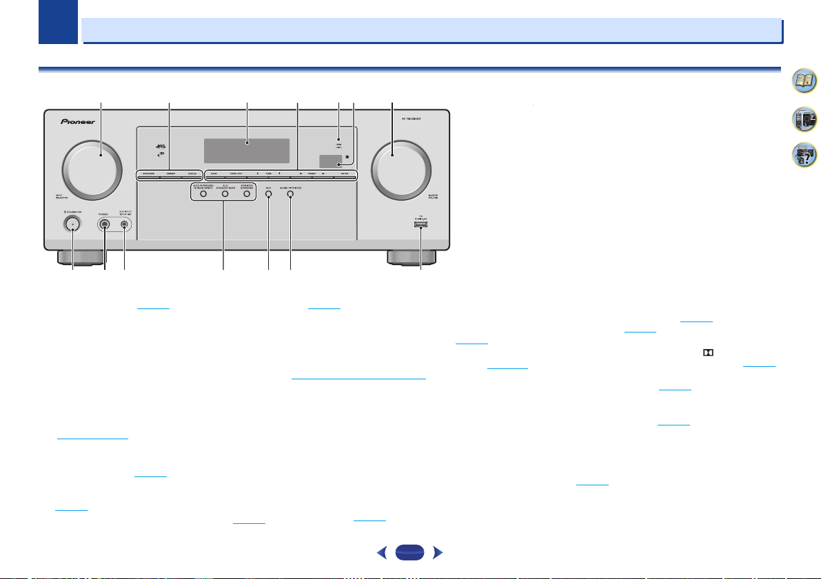
Front panel
1
INPUT SELECTOR
Selects an input source (page 18).
2
Receiver control buttons
SPEAKERS
off. When the SP OFF is selected, no sound is output
from the speakers connected to this receiver.
DIMMER
– Dims or brightens the display. The brightness
can be controlled in four steps.
STATUS
– Switches the display of this unit. The listening
mode, sound volume, input name can be checked by
selecting an input source.
3
Character display
See Display on page 5.
4
Tuner control buttons
BAND
– Switches between AM, FM ST (stereo) and FM
MONO radio bands (page 22
TUNER EDIT
and
ENTER
(page 22
).
TUNE/ – Used to find radio frequencies (page 22).
dial
– Use to change the speaker system on or
– Use with
to memorize and name stations for recall
).
TUNE/,
PRESET/
PRESET/ – Use to select preset radio stations
(page 23
).
5
HDMI indicator
Blinks when connecting an HDMI-equipped component;
lights when the component is connected (page 12
6
Remote sensor
Receives the signals from the remote control (see Operating
range of remote control on page 7).
7
MASTER VOLUME
8
Í
STANDBY/ON
9
PHONES jack
Use to connect headphones. When the headphones are
connected, there is no sound output from the speakers. The
listening mode when the sound is heard from the headphone
can be selected only from PHONES SURR, STEREO or
STEREO ALC mode.
10
AUX INPUT jack
Use to connect other equipment with a stereo mini jack.
Use to connect a microphone when performing Full Auto
MCACC setup (page 16
dial
/SETUP MIC jack
).
).
11
Listening mode buttons
AUTO SURROUND/STREAM DIRECT
between Auto surround mode (page 24
Direct playback (page 25
ALC/STANDARD SURR
and to switch between the modes of Pro Logic and
NEO:6, and the Auto level control stereo mode (page 24
ADVANCED SURROUND
various surround modes (page 25
12
ECO
Switches between ECO 1/ECO 2. When ECO Mode is turned
ON, the display will go dark (page 25
13
SOUND RETRIEVER
Turn Advanced Sound Retriever effect on/off.
14
USB terminal
Use to connect your USB mass storage device as an audio
source (page 15
).
).
– Press for standard decoding
– Switches between the
).
).
– Switches
) and Stream
2
4
33
).
4
1
15 16 17 18 19 17
22 23 24 25 25 26
20
21
1
Controls and displays
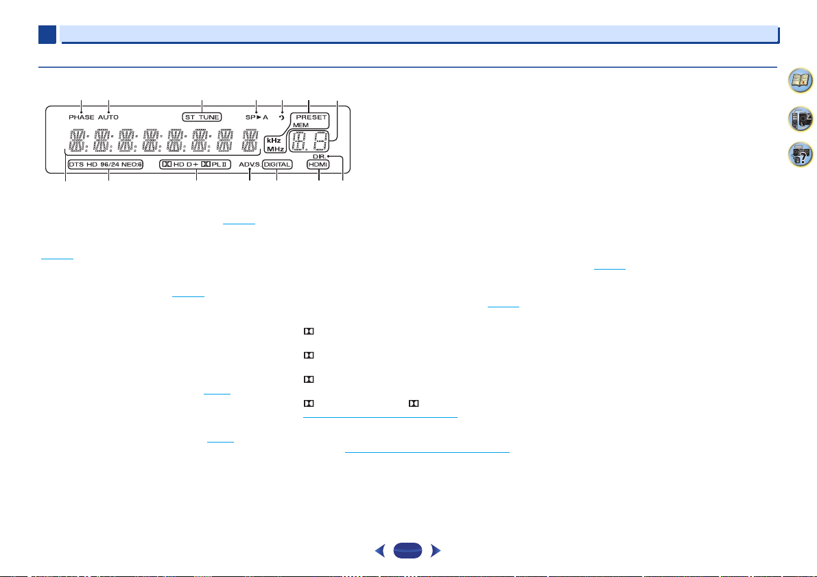
Display
15
PHASE
Lights when the Phase Control is switched on (page 26).
16
AUTO
Lights when the Auto Surround feature is switched on
(page 24
).
17
Tuner indicators
ST – Lights when a stereo FM broadcast is being
received in auto stereo mode (page 22
TUNE – Lights when a normal broadcast channel.
PRESET – Shows when a preset radio station is
registered or called.
MEM – Blinks when a radio station is registered.
kHz/MHz – Lights when the character display is showing
the currently received AM/FM broadcast frequency.
18
Speaker indicators
Shows if the speaker system is on or not (page 4).
SPA means the speakers are switched on.
SP means the speakers are switched off.
19
Sleep timer indicator
Lights when the receiver is in sleep mode (page 6).
20
PRESET information or input signal indicator
Shows the preset number of the tuner or the input signal
type, etc.
21
Character display
Displays various system information.
).
22
DTS indicators
DTS – Lights when a source with DTS encoded audio
signals is detected.
HD – Lights when a source with DTS-EXPRESS or DTSHD encoded audio signals is detected.
96/24 – Lights when a source with DTS 96/24 encoded
audio signals is detected.
NEO:6 – When one of the NEO:6 modes of the receiver
is on, this lights to indicate NEO:6 processing (page 24
23
Dolby Digital indicators
D – Lights when a Dolby Digital encoded signal is
detected.
D+ – Lights when a source with Dolby Digital Plus
encoded audio signals is detected.
HD – Lights when a source with Dolby TrueHD
encoded audio signals is detected.
PLII – Lights to indicate Pro Logic II decoding (see
Listening in surround sound
24
ADV.S.
Lights when one of the Advanced Surround modes has been
selected (see Using the Advanced surround
more on this).
25
SIGNAL SELECT indicators
DIGITAL – Lights when a digital audio signal is selected.
Blinks when a digital audio signal is selected and
selected audio input is not provided.
on page 24 for more on this).
on page 25 for
HDMI – Lights when an HDMI signal is selected. Blinks
when an HDMI signal is selected and selected HDMI
input is not provided.
26
DIR.
Lights when the DIRECT or PURE DIRECT mode is
switched on (page 25
).
).
2
4
33
5
1
RECEIVERRECEIVER AUDIO SELAUDIO SEL
DISPDISP
TUNERTUNER
EDITEDIT SLEEPSLEEP
TUNETUNE
+
TUNETUNE
-
STATUSSTATUS
PRESETPRESET
-
PRESETPRESET
+
PHASEPHASE
S.RETRIEVERS.RETRIEVER
BANDBAND
USBUSB
AVAV
ADJUSTADJUST
MUTEMUTE
HOMEHOME
MENUMENU
RETURNRETURN
SATSAT
STREAM BOXSTREAM BOX
BT AUDIOBT AUDIO
DVDDVD
TOPTOP
MENU MENU
TRETRE
BASSBASS
VOLUMEVOLUME
1
2
11
12
13
14
15
4
3
5
7
6
8
9
10
CBLCBLBDBD
S.BOXS.BOX
CDCD
GAMEGAME
TVTV
USBUSBTUNTUN
AUXAUX
BTBT
1
Controls and displays
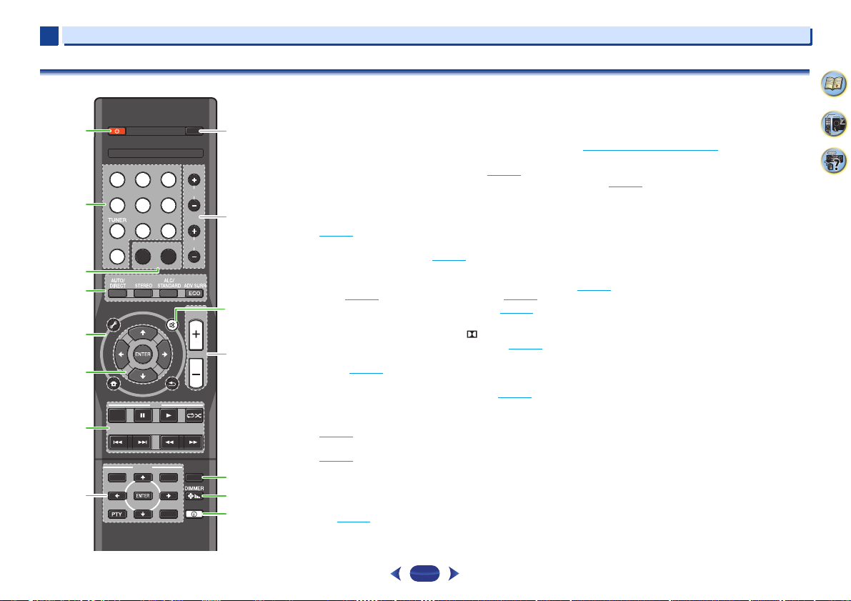
Remote control
As for operating other devices, the remote control codes for
the Pioneer products are preset. The settings cannot be
changed.
1
Í
RECEIVER
Switches the receiver between standby and on.
2
Input function buttons
Use to select the input source to this receiver (page 18). This
will enable you to control other Pioneer components with the
remote control.
3
Sound control buttons
PHASE
– Press to switch on/off Phase Control
(page 26
).
S.RETRIEVER
compressed audio sources (page 26
4
Listening mode and component control buttons
AUTO/DIRECT
mode (page 24
STEREO
ALC/STANDARD SURR
and to switch between the modes of Pro Logic II and
NEO:6, and the Auto level control stereo mode (page 24
ADV SURR
modes (page 25
ECO
– Switches between ECO 1/ECO 2. When ECO
Mode is turned ON, the display will go dark (page 25
5
Receiver control buttons
AV ADJUST
(page 26
HOME MENU
(page 29
RETURN
previous when making settings
6
///, ENTER
Use the arrow buttons when setting up your surround sound
system (page 29
– Press to restore CD quality sound to
– Switches between Auto surround
) and Stream Direct playback (page 25).
– Press to select stereo playback (page 24).
– Switches between the various surround
– Use to access the Audio options
).
– Press to access the Home Menu
).
– Use to return to the display immediately
).
– Press for standard decoding
).
).
).
6
7
USB
control buttons
Use to control the
are not possible.
8
TUNER
See Listening to the radio on page 22.
9
AUDIO SEL
Press to select the audio input signal of the component to
play back (page 18
10
BASS +/–, TRE +/–
Use to adjust Bass or Treble.
•
These controls are disabled when the listening mode is set
to DIRECT or PURE DIRECT.
•
When the front speaker is set at SMALL in the Speaker
Setting (or automatically via the Full Auto MCACC setup)
and the X.Over is set above 150 Hz, the subwoofer
channel level will be adjusted by pressing
(page 30
11
MUTE
Mutes/unmutes the sound.
12
VOLUME +/–
Use to set the listening volume.
).
13
SLEEP
Press to change the amount of time before the receiver
switches into standby (30 min – 60 min – 90 min – Off). You
can check the remaining sleep time at any time by pressing
SLEEP
once.
14
DIMMER
Dims or brightens the display. The brightness can be
controlled in four steps.
15
STATUS
Switches the display of this unit. The listening mode, sound
volume or input name can be checked by selecting an input
source.
USB
source. Operations other than USB
control buttons
).
).
BASS +/–
2
4
33
1
WARNING
CAUTION
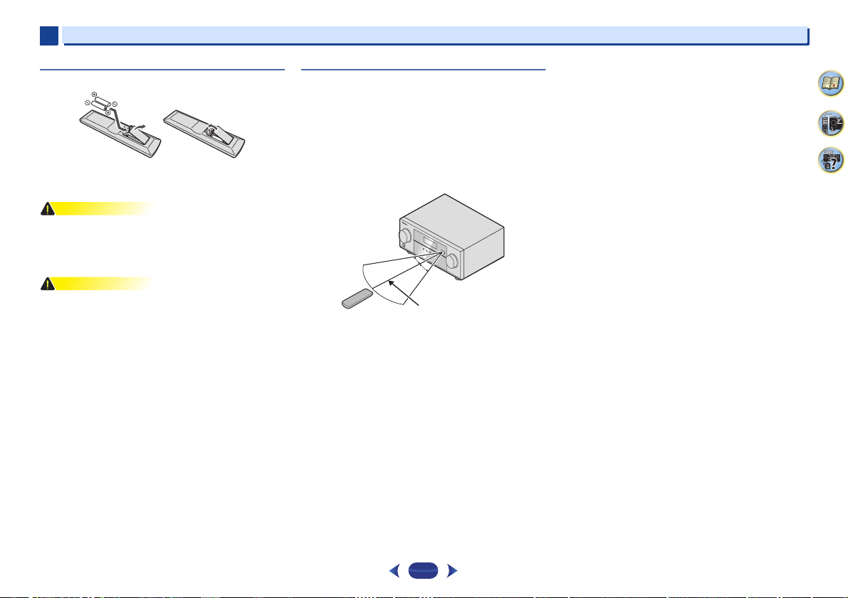
30°
7 m (23 ft.)
30°
1
Controls and displays
Loading the batteries
The batteries included with the unit are to check initial
operations; they may not last over a long period. We
recommend using alkaline batteries that have a longer life.
•
Do not use or store batteries in direct sunlight or other
excessively hot place, such as inside a car or near a
heater. This can cause batteries to leak, overheat, explode
or catch fire. It can also reduce the life or performance of
batteries.
•
Incorrect use of batteries may result in such hazards as
leakage and bursting. Observe the following precautions:
-
Never use new and old batteries together.
-
Insert the plus and minus sides of the batteries properly
according to the marks in the battery case.
-
Batteries with the same shape may have different
voltages. Do not use different batteries together.
-
When disposing of used batteries, please comply with
governmental regulations or environmental public
institution’s rules that apply in your country/area.
-
When inserting the batteries, make sure not to damage
the springs on the battery’s (–) terminals. This can cause
batteries to leak or overheat.
Operating range of remote control
The remote control may not work properly if:
•
There are obstacles between the remote control and the
receiver’s remote sensor.
•
Direct sunlight or fluorescent light is shining onto the
remote sensor.
•
The receiver is located near a device that is emitting
infrared rays.
•
The receiver is operated simultaneously with another
infrared remote control unit.
2
4
33
7
Connecting your equipment
CAUTION
120
120
SL
L
SW
C
R
SR
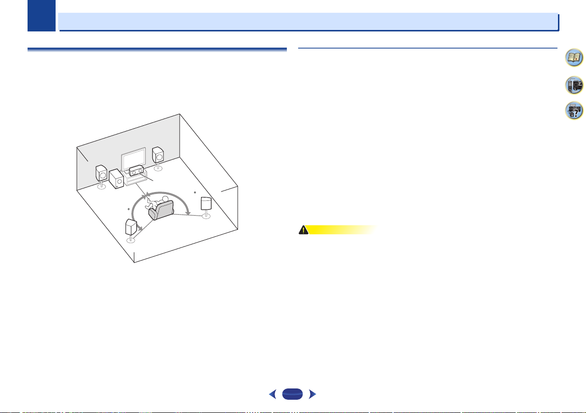
5.1 channel surround system:
2
2
Placing the speakers
By connecting the left and right front speakers (L/R), the center speaker (C), the left and right
surround speakers (SL/SR), and the subwoofer (SW), a 5.1 ch surround system can be
enjoyed.
To achieve the best possible surround sound, install your speakers as shown below.
Hints on the speaker placement
Where you put your speakers in the room has a big effect on the quality of the sound. The
following guidelines should help you to get the best sound from your system.
•
The subwoofer can be placed on the floor. Ideally, the other speakers should be at about
ear-level when you’re listening to them. Putting the speakers on the floor (except the
subwoofer), or mounting them very high on a wall is not recommended.
•
For the best stereo effect, place the front speakers 2 m to 3 m (6 ft. to 9 ft.) apart, at equal
distance from the TV.
•
If you’re going to place speakers around your CRT TV, use shielded speakers or place the
speakers at a sufficient distance from your CRT TV.
•
If you’re using a center speaker, place the front speakers at a wider angle. If not, place
them at a narrower angle.
•
Place the center speaker above or below the TV so that the sound of the center channel is
localized at the TV screen. Also, make sure the center speaker does not cross the line
formed by the leading edge of the front left and right speakers.
•
It is best to angle the speakers towards the listening position. The angle depends on the
size of the room. Use less of an angle for bigger rooms.
•
The optimal positioning for surround speakers is just above ear height. Make sure the
speakers don’t face each other. For DVD-Audio, the speakers should be more directly
behind the listener than for home theater playback.
•
Try not to place the surround speakers farther away from the listening position than the
front and center speakers. Doing so can weaken the surround sound effect.
•
Make sure that all speakers are securely installed. This not only improves sound quality,
but also reduces the risk of damage or injury resulting from speakers being knocked over
or falling in the event of external shocks such as earthquakes.
2
4
33
8
2
CAUTION
12 mm
(1/2 in.)
12 3
12 mm
(1/2 in.)
Center
Surround right
Front right
Front leftSubwoofer
Surround left
2
Connecting your equipment
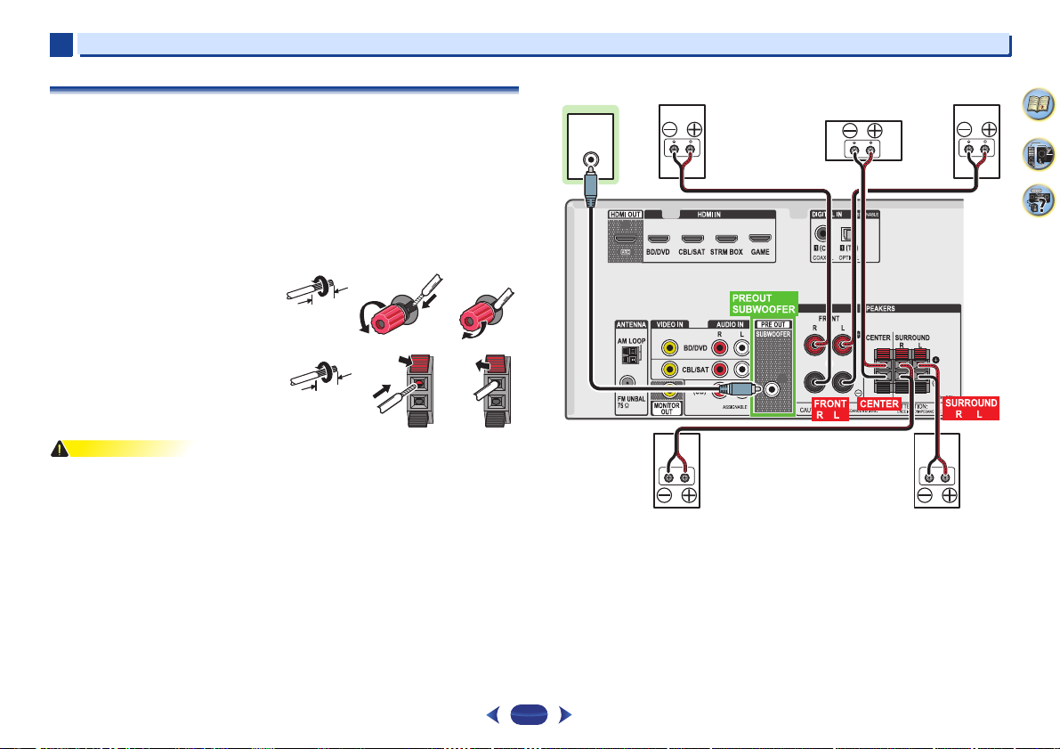
Connecting the speakers
The receiver will work with just two stereo speakers (the front speakers in the diagram) but
using at least three speakers is recommended, and a complete setup is best for surround
sound.
Make sure you connect the speaker on the right to the right (R) terminal and the speaker on
the left to the left (L) terminal. Also make sure the positive and negative (+/–) terminals on the
receiver match those on the speakers.
You can use speakers with a nominal impedance between 6 Ω and 16 Ω.
Be sure to complete all connections before connecting this unit to the AC power source.
Bare wire connections
Front speaker terminals:
1
Twist exposed wire strands together.
2
Loosen terminal and insert exposed wire.
3
Tighten terminal.
Center and surround speaker terminals:
1
Twist exposed wire strands together.
2
Push open the tabs and insert exposed wire.
3
Release the tabs.
•
These speaker terminals carry HAZARDOUS LIVE voltage. To prevent the risk of electric
shock when connecting or disconnecting the speaker cables, disconnect the power cord
before touching any uninsulated parts.
•
Make sure that all the bare speaker wire is twisted together and inserted fully into the
speaker terminal. If any of the bare speaker wire touches the back panel it may cause the
power to cut off as a safety measure.
12 3
LINE LEVEL
INPUT
2
4
33
9
2
Important
Note
Note
HDMI
®
2
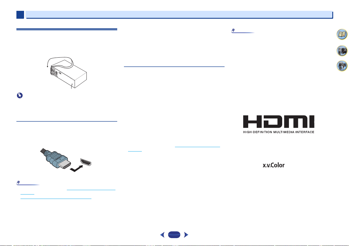
Making cable connections
Make sure not to bend the cables over the top of this unit (as
shown in the illustration). If this happens, the magnetic field
produced by the transformers in this unit may cause a
humming noise from the speakers.
•
Before making or changing connections, switch off the
power and disconnect the power cord from the AC outlet.
•
Before unplugging the power cord, switch the power into
standby.
HDMI cables
Both video and sound signals can be transmitted
simultaneously with one cable. If connecting the player and
the TV via this receiver, for both connections, use HDMI
cables.
Be careful to connect the terminal in the proper direction.
•
Set the HDMI parameter in Setting the Audio options on
page 26 to THRU (THROUGH) and set the input signal in
Selecting the audio input signal
want to hear HDMI audio output from your TV (no sound
will be heard from this receiver).
on page 18 to HDMI, if you
•
If the video signal does not appear on your TV, try
adjusting the resolution settings on your component or
display. Note that some components (such as video game
units) have resolutions that may not be displayed. In this
case, use a (analog) composite connection.
•
When the video signal from the HDMI is 480i, 480p, 576i
or 576p, Multi Ch PCM sound and HD sound cannot be
received.
About HDMI
The HDMI connection transfers uncompressed digital video,
as well as almost every kind of digital audio that the
connected component is compatible with, including DVDVideo, DVD-Audio, SACD, Dolby Digital Plus, Dolby
TrueHD, DTS-HD Master Audio (see below for limitations),
Video CD/Super VCD and CD.
This receiver incorporates High-Definition Multimedia
Interface (HDMI
This receiver supports the functions described below through
HDMI connections.
•
Digital transfer of uncompressed video (contents
protected by HDCP (1080p/24, 1080p/60, etc.))
•
3D signal transfer
•
Deep Color signal transfer
•
x.v.Color signal transfer
•
Audio Return Channel (see The HDMI Setup menu on
page 32)
•
Input of multi-channel linear PCM digital audio signals
(192 kHz or less) for up to 8 channels
•
Input of the following digital audio formats:
– Dolby Digital, Dolby Digital Plus, DTS, High bitrate audio
(Dolby TrueHD, DTS-HD Master Audio), DVD-Audio, CD,
SACD (DSD 2 ch only), Video CD, Super VCD
•
4K signal transfer
– This may not operate properly, depending on the
connected equipment.
– 4K 24p, 4K 25p, 4K 30p, 4K 50p and 4K 60p signals are
supported.
•
HDCP 2.2 compatible terminal
®
) technology.
Connecting your equipment
•
Use a High Speed HDMI®/™ Cable. If HDMI cable other
than a High Speed HDMI
work properly.
•
When an HDMI cable with a built-in equalizer is
connected, it may not operate properly.
•
3D, Deep Color, x.v.Color, 4K signal transfer and Audio
Return Channel are only possible when connected to a
compatible component.
•
HDMI format digital audio transmissions require a longer
time to be recognized. Due to this, interruption in the audio
may occur when switching between audio formats or
beginning playback.
•
Turning on/off the device connected to this unit’s HDMI
OUT terminal during playback, or disconnecting/
connecting the HDMI cable during playback, may cause
noise or interrupted audio.
The terms HDMI and HDMI High-Definition Multimedia
Interface, and the HDMI Logo are trademarks or registered
trademarks of HDMI Licensing, LLC in the United States and
other countries.
“x.v.Color” and are trademarks of Sony
Corporation.
®/
™ Cable is used, it may not
2
4
33
10
2
Note
White (Left)
Red (Right)
COAXIAL
IN
OPTICAL
IN
Coaxial digital
audio cable
Optical cable
VIDEO
Yellow
VIDEO
VIDEO
IN
IN
HDMI
MONITOR
OUT
HDMI
OUT
Terminal for connection
with source device
T e r m i n a l f o r c o n n e c t i o n
with TV monitor
Playback component
TV
The OSD will
not appear.
Video signals can be output.
2
Connecting your equipment
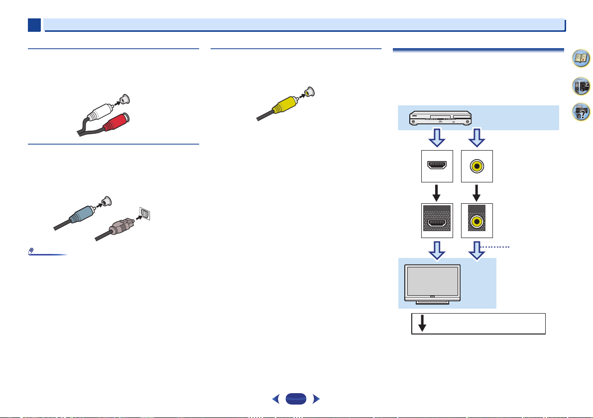
Analog audio cables
Use stereo RCA phono cables to connect analog audio
components. These cables are typically red and white, and
you should connect the red plugs to R (right) terminals and
white plugs to L (left) terminals.
L
AUDIO
R
Digital audio cables
Commercially available coaxial digital audio cables or optical
cables should be used to connect digital components to this
receiver.
•
When connecting optical cables, be careful when inserting
the plug not to damage the shutter protecting the optical
socket.
•
When storing optical cable, coil loosely. The cable may be
damaged if bent around sharp corners.
•
You can also use a standard RCA video cable for coaxial
digital connections.
Standard RCA video cables
These cables are the most common type of video connection
and are used to connect to the composite video terminals.
The yellow plugs distinguish them from cables for audio.
About video outputs connection
This receiver is not loaded with a video converter. When you
use HDMI cables for connecting to the input device, the
same cables should be used for connecting to the TV.
The signals input from the analog (composite) video inputs of
this unit will not be output from the HDMI OUT.
2
4
33
11
2
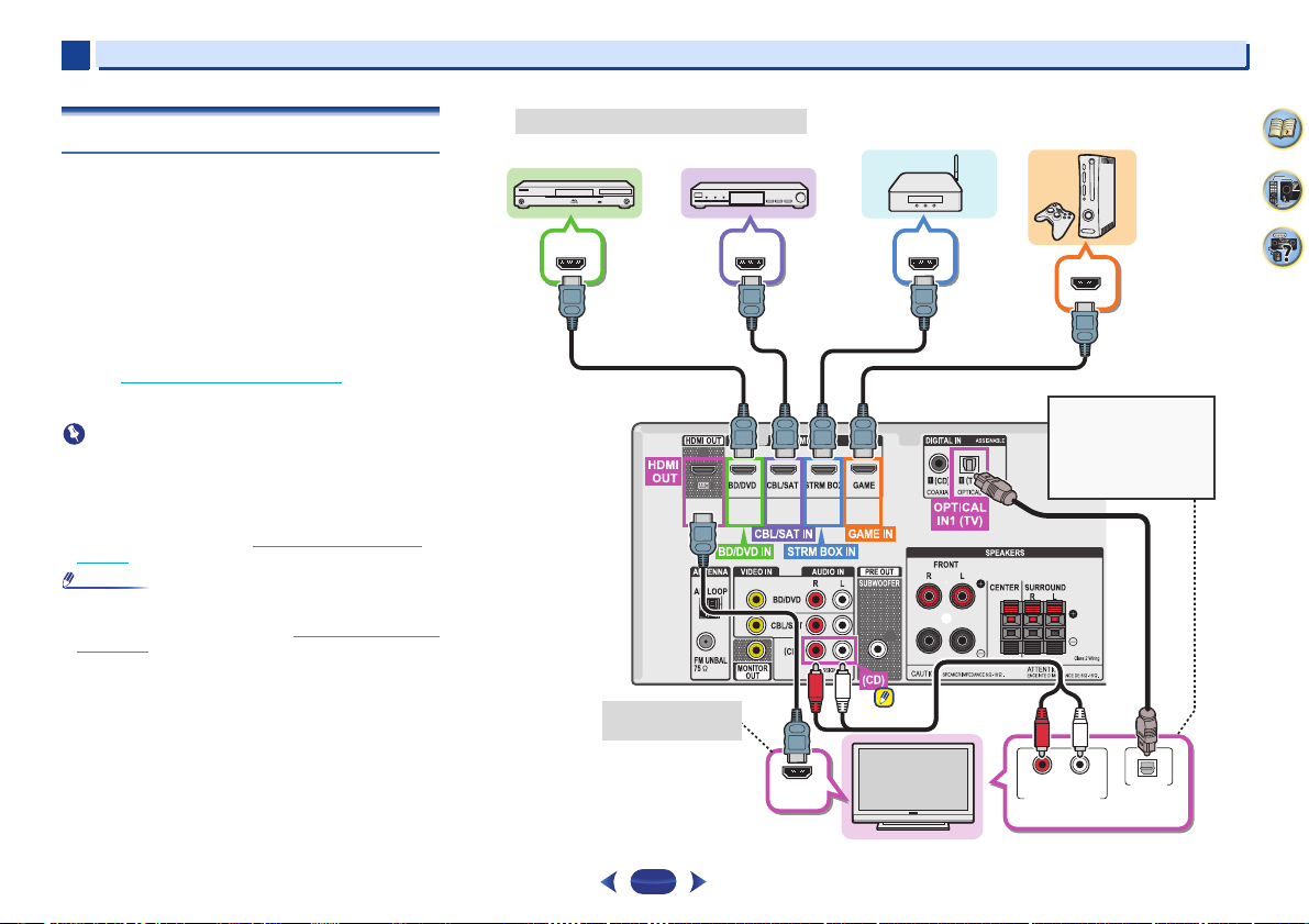
Important
Note
HDMI IN
DIGITAL AUDIO OUT
OPTICAL
RL
ANALOG AUDIO OUT
HDMI OUTHDMI OUT HDMI OUT
HDMI OUT
Select one
HDMI/DVI-compatible TV
Blu-ray Disc /DVD
player
Set-top box
Game console
HDMI/DVI-compatible components
If the TV does not support
the HDMI Audio Return
Channel function, this
connection is required to
listen to the TV sound over
the receiver.
OSD can only be
output from HDMI.
Streaming media player
2
Connecting your equipment
Connecting a TV and playback components
Connecting using HDMI
If you have an HDMI or DVI (with HDCP) equipped
component (Blu-ray Disc player, etc.), you can connect it to
this receiver using a commercially available HDMI cable.
•
The following connection/setting is required to listen to the
sound of the TV over this receiver.
-
If the TV does not support the HDMI Audio Return
Channel function, connect the receiver and TV with
audio cables (as shown).
-
If the TV supports the HDMI Audio Return Channel
function, the sound of the TV is input to the receiver via
the HDMI terminal, so there is no need to connect an
audio cable. In this case, set ARC at HDMI Setup to ON
(see The HDMI Setup menu
-
Please refer to the TV’s operation manual for directions
on connections and setup for the TV.
•
When the ARC function is ON and the receiver is
connected to a compatible TV with an HDMI cable, and
you switch the input of the TV to composite, the input of the
receiver may automatically switch to TV. If this happens,
switch the receiver’s input back to the original input, or turn
OFF the ARC function (see The HDMI Setup menu
page 32).
•
In order to listen to the audio from the TV that is connected
to this receiver using an analog audio cables, set-up for
analog audio input is required (see The Input Assign menu
on page 31).
on page 32).
on
2
4
33
12
 Loading...