

Page 1

AUDIO/VIDEO MULTI-CHANNEL RECEIVER
RECEPTEUR AUDIOVISUEL MULTICANAL
SINTOAMPLIFICATORE AUDIO/VIDEO MULTICANALE
AUDIO/VIDEO MULTIKANAALS RECEIVER
RECEPTOR AUDIO-VIDEO MULTICANAL
AUDIO-/VIDEO- MEHRKANAL-RECEIVER
Quick Start Guide
Guide rapide
Guida di avvio rapido
Snelstartgids
Guía de inicio rápido
Kurzanleitung
Discover the benefits of registering your product online at
http://www.pioneer.co.uk
(or http://www.pioneer.eu).
Découvrez les nombreux avantages offerts en enregistrant votre produit en ligne maintenant sur
http://www.pioneer.fr
(ou http://www.pioneer.eu).
Зарегистрируйте Baшe изделие на
http://www.pioneer-rus.ru
(или http://www.pioneer.eu). Oзнакомьтесь с преимуществами
регистрации в Интернет
Registra il tuo prodotto su
http://www.pioneer.it
(o http://www.pioneer.eu) e scopri subito quali vantaggi puoi ottenere!
Ontdek nu de voordelen van online registratie! Registreer uw Pioneer product via
http://www.pioneer.nl - http://www.pioneer.be
(of http://www.pioneer.eu).
Registre su producto en
http://www.pioneer.es
(o en http://www.pioneer.eu) Descubra los beneficios de registrarse on-line:
Bitte nutzen Sie die Möglichkeit zur Registrierung Ihres Produktes unter
http://www.pioneer.de
(oder http://www.pioneer.eu)
VSX-521-
K
Page 2
IMPORTANT
WARNING
To prevent a fire hazard, do not place any naked flame
sources (such as a lighted candle) on the equipment.
D3-4-2-1-7a_A1_En
VENTILATION CAUTION
When installing this unit, make sure to leave space
around the unit for ventilation to improve heat radiation
(at least 40 cm at top, 20 cm at rear, and 20 cm at each
side).
WARNING
Slots and openings in the cabinet are provided for
ventilation to ensure reliable operation of the product,
and to protect it from overheating. To prevent fire
hazard, the openings should never be blocked or
covered with items (such as newspapers, table-cloths,
curtains) or by operating the equipment on thick carpet
or a bed.
D3-4-2-1-7b*_A1_En
Operating Environment
Operating environment temperature and humidity:
+5 °C to +35 °C (+41 °F to +95 °F); less than 85 %RH
(cooling vents not blocked)
Do not install this unit in a poorly ventilated area, or in
locations exposed to high humidity or direct sunlight (or
strong artificial light)
D3-4-2-1-7c*_A1_En
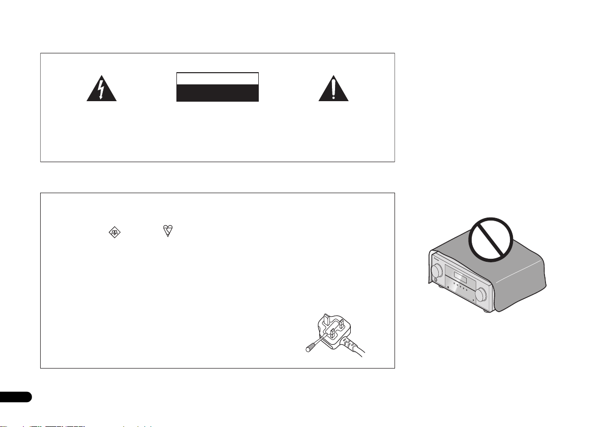
The lightning flash with arrowhead symbol,
within an equilateral triangle, is intended to
alert the user to the presence of uninsulated
“dangerous voltage” within the product’s
enclosure that may be of sufficient
magnitude to constitute a risk of electric
shock to persons.
Replacement and mounting of an AC plug on the power supply cord of this unit should be performed only by qualified
service personnel.
IMPORTANT: THE MOULDED PLUG
This appliance is supplied with a moulded three pin mains plug for your safety and convenience. A 10 amp fuse is fitted in this plug.
Should the fuse need to be replaced, please ensure that the replacement fuse has a rating of 10 amps and that it is approved by ASTA or BSI
to BS1362.
Check for the ASTA mark or the BSI mark on the body of the fuse.
If the plug contains a removable fuse cover, you must ensure that it is refitted when the fuse is replaced. If you lose the fuse cover the plug
must not be used until a replacement cover is obtained. A replacement fuse cover can be obtained from your local dealer.
If the fitted moulded plug is unsuitable for your socket outlet, then the fuse shall be removed and the plug cut off and disposed of
safely. There is a danger of severe electrical shock if the cut off plug is inserted into any 13 amp socket.
If a new plug is to be fitted, please observe the wiring code as shown below. If in any doubt, please consult a qualified electrician.
IMPORTANT: The wires in this mains lead are coloured in accordance with the following code:
Blue : Neutral Brown : Live
As the colours of the wires in the mains lead of this appliance may not correspond with the coloured markings identifying the terminals in
your plug, proceed as follows;
The wire which is coloured BLUE must be connected to the terminal which is marked with the
letter N or coloured BLACK.
The wire which is coloured BROWN must be connected to the terminal which is marked with the
letter L or coloured RED.
How to replace the fuse: Open the fuse compartment with a screwdriver and replace the fuse.
2
En
CAUTION:
TO PREVENT THE RISK OF ELECTRIC
SHOCK, DO NOT REMOVE COVER (OR
BACK). NO USER-SERVICEABLE PARTS
INSIDE. REFER SERVICING TO QUALIFIED
SERVICE PERSONNEL.
CAUTION
RISK OF ELECTRIC SHOCK
DO NOT OPEN
The exclamation point within an equilateral
triangle is intended to alert the user to the
presence of important operating and
maintenance (servicing) instructions in the
literature accompanying the appliance.
D3-4-2-1-1_A1_En
D3-4-2-1-2-2*_A2_En
Page 3
English
Français
Italiano
Español
Nederlands
Deutsch
This product is for general household purposes. Any
failure due to use for other than household purposes
(such as long-term use for business purposes in a
restaurant or use in a car or ship) and which requires
repair will be charged for even during the warranty
period.
K041_A1_En
WARNING
This equipment is not waterproof. To prevent a fire or
shock hazard, do not place any container filled with
liquid near this equipment (such as a vase or flower
pot) or expose it to dripping, splashing, rain or
moisture.
D3-4-2-1-3_A1_En
WARNING
Before plugging in for the first time, read the following
section carefully.
The voltage of the available power supply differs
according to country or region. Be sure that the
power supply voltage of the area where this unit
will be used meets the required voltage (e.g., 230 V
or 120 V) written on the rear panel.
D3-4-2-1-4*_A1_En
Information for users on collection and disposal of old equipment and used batteries
Symbol for
equipment
Symbol examples
for batteries
Pb
These symbols on the products, packaging, and/or accompanying documents mean
that used electrical and electronic products and batteries should not be mixed with
general household waste.
For proper treatment, recovery and recycling of old products and used batteries,
please take them to applicable collection points in accordance with your national
legislation.
By disposing of these products and batteries correctly, you will help to save valuable
resources and prevent any potential negative effects on human health and the
environment which could otherwise arise from inappropriate waste handling.
For more information about collection and recycling of old products and batteries,
please contact your local municipality, your waste disposal service or the point of sale
where you purchased the items.
These symbols are only valid in the European Union.
For countries outside the European Union:
If you wish to discard these items, please contact your local authorities or dealer and
ask for the correct method of disposal.
K058a_A1_En
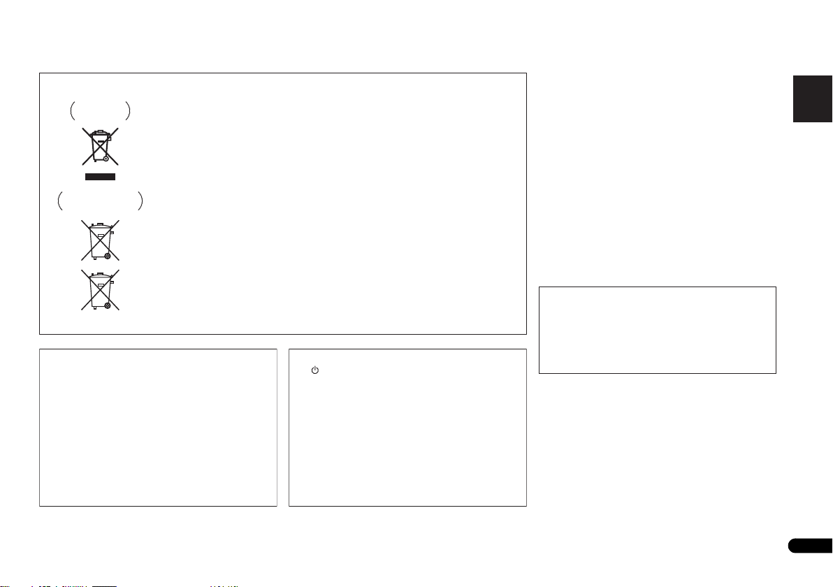
If the AC plug of this unit does not match the AC
outlet you want to use, the plug must be removed
and appropriate one fitted. Replacement and
mounting of an AC plug on the power supply cord of
this unit should be performed only by qualified
service personnel. If connected to an AC outlet, the
cut-off plug can cause severe electrical shock. Make
sure it is properly disposed of after removal.
The equipment should be disconnected by removing
the mains plug from the wall socket when left unused
for a long period of time (for example, when on
vacation).
D3-4-2-2-1a_A1_En
CAUTION
The STANDBY/ON switch on this unit will not
completely shut off all power from the AC outlet.
Since the power cord serves as the main disconnect
device for the unit, you will need to unplug it from the
AC outlet to shut down all power. Therefore, make
sure the unit has been installed so that the power
cord can be easily unplugged from the AC outlet in
case of an accident. To avoid fire hazard, the power
cord should also be unplugged from the AC outlet
when left unused for a long period of time (for
example, when on vacation).
D3-4-2-2-2a*_A1_En
3
En
Page 4

Thank you for buying this pioneer product.
This Quick Start Guide includes instructions for basic
connections and operations to allow simple use of the
receiver. For detailed descriptions of the receiver, see the
“Operating Instructions” provided on the included CDROM. The operating instructions can also be
downloaded from the Pioneer website (http://
www.pioneer.eu).
See below for instructions on handling the CD-ROM.
Operating Environment
This CD-ROM can be used with Microsoft® Windows®
95/98/Me/NT/2000/XP/Vista/7 and Apple Mac OS X 10.4.
Adobe Reader (Version 4.0 or later) is required to read
this CD-ROM.
=========================================================================================================
Contents
Before you start
Checking what’s in the box . . . . . . . . . . . . . . . . . . . . . . . . 5
Loading the batteries. . . . . . . . . . . . . . . . . . . . . . . . . . . . . 5
Flow of settings on the receiver . . . . . . . . . . . . . . . . . . . . .5
Remote control
Connecting your equipment
Placing the speakers. . . . . . . . . . . . . . . . . . . . . . . . . . . . . 7
Hints on the speaker placement. . . . . . . . . . . . . . . . . . . 7
Connecting the speakers. . . . . . . . . . . . . . . . . . . . . . . . . . 8
Connect the surround back or front height speakers . . . 8
Making cable connections . . . . . . . . . . . . . . . . . . . . . . . . 9
HDMI cables . . . . . . . . . . . . . . . . . . . . . . . . . . . . . . . . . 9
About HDMI. . . . . . . . . . . . . . . . . . . . . . . . . . . . . . . . . . 9
Analog audio cables. . . . . . . . . . . . . . . . . . . . . . . . . . . 10
Digital audio cables . . . . . . . . . . . . . . . . . . . . . . . . . . . 10
Video cables. . . . . . . . . . . . . . . . . . . . . . . . . . . . . . . . . 10
About video outputs connection . . . . . . . . . . . . . . . . . . . 10
Connecting a TV and playback components . . . . . . . . . . 11
Connecting using HDMI . . . . . . . . . . . . . . . . . . . . . . . 11
Connecting your component with no HDMI terminal
Connecting a satellite receiver or other digital
set-top box. . . . . . . . . . . . . . . . . . . . . . . . . . . . . . . . . . . . 12
. . . . . . . . . . . . . . . . . . . . . . . . . . . . 5
. . . . . . . . . . . . . . . . . . . . . . . . . . . . . 6
. . . . . . . . . . . . . . . . . 7
. . . 12
Precautions For Use
This CD-ROM is for use with a personal computer. It
cannot be used with a DVD player or music CD player.
Attempting to play this CD-ROM with a DVD player or
music CD player can damage speakers or cause
impaired hearing due to the large volume.
License
Please agree to the “Terms of Use” indicated below
before using this CD-ROM. Do not use if you are
unwilling to consent to the terms of its use.
Terms of Use
Copyright to data provided on this CD-ROM belongs to
Pioneer Corporation. Unauthorized transfer, duplication,
broadcast, public transmission, translation, sales,
lending or other such matters that go beyond the scope
Connecting an HDD/DVD recorder, Blu-ray Disc
recorder and other video sources . . . . . . . . . . . . . . . . . . 13
Using the component video jacks. . . . . . . . . . . . . . . . . . 13
Connecting other audio components . . . . . . . . . . . . . . . 14
Connecting antennas . . . . . . . . . . . . . . . . . . . . . . . . . . . 14
Using external antennas . . . . . . . . . . . . . . . . . . . . . . . 14
Plugging in the receiver . . . . . . . . . . . . . . . . . . . . . . . . . 15
Basic Setup
Canceling the demo display . . . . . . . . . . . . . . . . . . . . . . 16
Automatically setting up for surround sound (MCACC)
Other problems when using the Auto MCACC setup
Basic playback
Playing a source . . . . . . . . . . . . . . . . . . . . . . . . . . . . . . . 18
Listening in surround sound. . . . . . . . . . . . . . . . . . . . . . 18
Standard surround sound . . . . . . . . . . . . . . . . . . . . . . 18
Using the Advanced surround effects . . . . . . . . . . . . . 18
Bluetooth
Music . . . . . . . . . . . . . . . . . . . . . . . . . . . . . . . . . . . . . . . 18
Listening to the radio . . . . . . . . . . . . . . . . . . . . . . . . . . . 19
Improving FM sound . . . . . . . . . . . . . . . . . . . . . . . . . . 19
Saving station presets . . . . . . . . . . . . . . . . . . . . . . . . . 19
Listening to station presets . . . . . . . . . . . . . . . . . . . . . 19
. . . . . . . . . . . . . . . . . . . . . . . . . . . . . . . 16
. . . . . . . . . . . . . . . . . . . . . . . . . . . . 18
®
ADAPTER for Wireless Enjoyment of
. . . 16
. . . 17
of “personal use” or “citation” as defined by Copyright
Law may be subject to punitive actions. Permission to
use this CD-ROM is granted under license by Pioneer
Corporation.
General Disclaimer
Pioneer Corporation does not guarantee the operation of
this CD-ROM with respect to personal computers using
any of the applicable OS. In addition, Pioneer
Corporation is not liable for any damages incurred as a
result of use of this CD-ROM and is not responsible for
any compensation. The names of private corporations,
products and other entities described herein are the
registered trademarks or trademarks of their respective
firms.
* When Using a Mac OS:
Place this CD-ROM in a CD drive and then double-click
on the CD-ROM icon to start up the application.
4
En
Page 5
Before you start
English
Français
Italiano
Español
Nederlands
Deutsch
CAUTION
Before you start
Checking what’s in the box
Please check that you’ve received the following supplied
accessories:
• Setup microphone
• Remote control
• AAA size IEC R03 dry cell batteries (to confirm system
operation) x2
• AM loop antenna
• FM wire antenna
•Power cord
• Warranty card
• Operating instructions (CD-ROM)
• These quick start guide
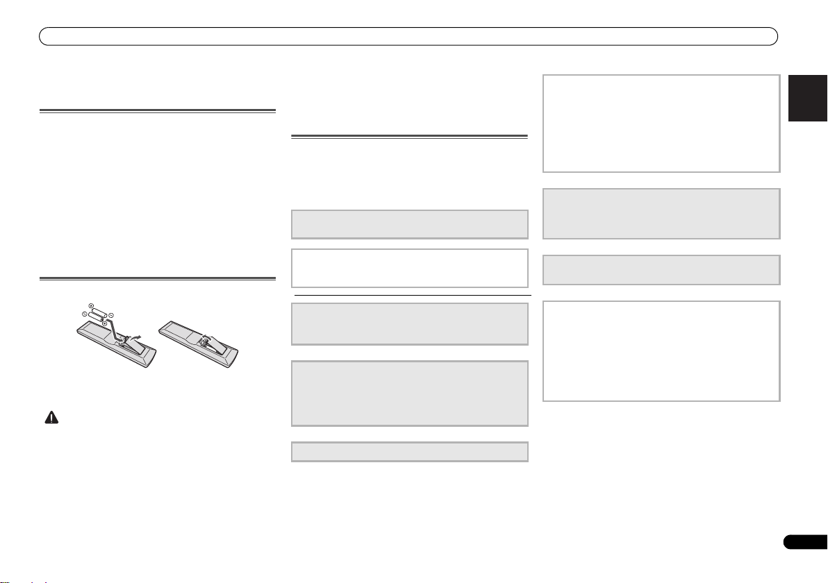
Loading the batteries
The batteries included with the unit are to check initial
operations; they may not last over a long period. We
recommend using alkaline batteries that have a longer life.
• Incorrect use of batteries may result in such hazards as
leakage and bursting. Observe the following precautions:
-
Never use new and old batteries together.
-
Insert the plus and minus sides of the batteries properly
according to the marks in the battery case.
-
Batteries with the same shape may have different
voltages. Do not use different batteries together.
-
When disposing of used batteries, please comply with
governmental regulations or environmental public
instruction’s rules that apply in your country or area.
-
Do not use or store batteries in direct sunlight or other
excessively hot place, such as inside a car or near a
heater. This can cause batteries to leak, overheat,
explode or catch fire. It can also reduce the life or
performance of batteries.
Flow of settings on the receiver
The unit is a full-fledged AV receiver equipped with an
abundance of functions and terminals. It can be used easily
after following the procedure below to make the connections
and settings.
The colors of the steps indicate the following:
Required setting item (These items are included in this
Quick Start Guide.)
Setting to be made as necessary (These items are
explained in the “Operating Instructions” provided on
the included CD-ROM.)
1
Connecting the speakers
• Placing the speakers (page 7)
• Connecting the speakers (page 8)
2
Connecting the components
• About video outputs connection (page 10)
• Connecting a TV and playback components (page 11)
• Connecting antennas (page 14)
• Plugging in the receiver (page 15)
3
Power On
4
The Pre Out Setting
(When connecting the front height speakers.)
The Input Assign menu
(When using connections other than the recommended
connections.)
Using the Audio Return Channel function
(When the connected TV supports the HDMI Audio
Return Channel function.)
5
Use the on-screen automatic MCACC setup to set up
your system
• Automatically setting up for surround sound (MCACC)
(page 16)
6
Playing a source (page 18)
• Listening in surround sound (page 18)
7
Adjusting the sound as desired
• Using the Sound Retriever
• Better sound using Phase Control
• Listening with Acoustic Calibration EQ
• Using surround back channel processing
• Setting the Up Mix function
• Setting the Audio options
• Manual speaker setup
5
En
Page 6
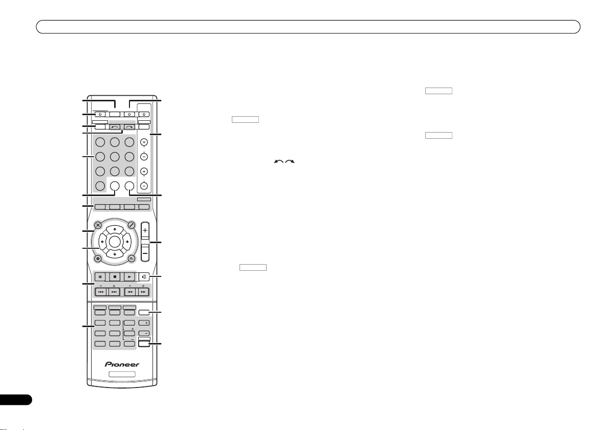
Remote control
RECEIVER
RECEIVER
RECEIVER
RECEIVER
6
En
Remote control
This section explains how to operate the remote control for
the receiver.
1
RECEIVER
2
RECEIVER DTV/TV
3
4
BD DVD
DVR/BDRCDCD-R
5
ADAPTER
VIDEO
6
AUTO/
DIRECT
7
AUDIO
PARAMETER
TOP
MENU
8
T
E
S
E
R
P
9
HOME
MENU
SETUP
PTY SEARCH
10
HDD
1
4
11
MIDNIGHT
7
DIMMER
CLR
+
BASS
10
INPUT SELECT
TUNER
STEREO
N
U
E
T
ENTER
T
E
U
N
DVD
2
SB CH
5
SPEAKERS
8
0
RECEIVER
SOURCESLEEP
TV
PORTABLE
SIGNAL SELS.RETRIEVER
ALC/
STANDARD
TUNER EDIT
TOOLS
RETURN
VCR
3
CH SELECT
6
LEV
9
LEV
ENTER
P
R
E
E
T
S
TRE
CONTROL
BD MENU
ADV SURR
MENU
BAND
TV
INPUT
CH
VOL
MASTER
VOLUME
MUTE
DISP
EQ
CH
PHASE
CH
SHIFT
12
13
14
15
16
17
18
1 SLEEP
Press to change the amount of time before the receiver
switches into standby (30 min – 60 min – 90 min – Off). You
can check the remaining sleep time at any time by pressing
SLEEP once.
2
RECEIVER
Switches the receiver between standby and on.
3
Switches the remote to control the receiver (used to select
the white commands above the number buttons
(MIDNIGHT, etc)). Also use this button to set up surround
sound or Audio parameters.
4 INPUT SELECT
Use to select the input source (page 18).
5 Input function buttons
Use to select the input source to this receiver (page 18). This
will enable you to control other Pioneer components with the
remote control.
6 S.RETRIEVER
Press to restore CD quality sound to compressed audio
sources.
7 Listening mode buttons
Press to select a listening mode (page 18).
8 Receiver setting buttons
Press first to access:
AUDIO PARAMETER – Use to access the Audio options.
SETUP – Press to access the System Setup menu.
RETURN – Confirm and exit the current menu screen.
Press TUNER first to access:
TUNER EDIT – Memorizes/names stations for recall
(page 19).
BAND – Switches between AM, FM ST (stereo) and FM
MONO radio bands (page 19).
PTY SEARCH – Use to search for RDS program types.
9
///
Use the arrow buttons when setting up your surround sound
system.
(TUNE
/
, PRESET
/
), ENTER
Use TUNE / can be used to find radio frequencies and
PRESET / can be used to select preset radio stations
(page 19).
10 Receiver control buttons
Press first to access:
BASS –/+, TRE –/+ – Use to adjust Bass or Treble.
• These controls are disabled when the listening mode is
set to DIRECT or PURE DIRECT.
11 Receiver control buttons
Press first to access:
SB CH – Press to select ON, AUTO or OFF the surround
back channel.
CH SELECT – Press repeatedly to select a channel, then
use LEV +/– to adjust the level.
LEV +/– – Use to adjust the channel level.
EQ – Press to switch on/off Acoustic Calibration EQ
setting.
MIDNIGHT – Switches to Midnight or Loudness listening.
SPEAKERS – Use to change the speaker system on or off.
PHASE – Press to switch on/off Phase Control.
DIMMER – Dims or brightens the display.
12
SOURCE
Press to turn on/off other components connected to the
receiver.
13 TV CONTROL buttons
These buttons can control only be used with Pioneer TVs.
14 SIGNAL SEL
Press to select the audio input signal of the component to
play back.
15 MASTER VOLUME +/–
Use to set the listening volume.
16 MUTE
Mutes/unmutes the sound.
17 DISP
Switches the display of this unit.
18 SHIFT
Press to access the ‘boxed’ commands (above the buttons)
on the remote.
Page 7
Connecting your equipment
English
Français
Italiano
Español
Nederlands
Deutsch
CAUTION
Important
120
120
SL
L
SW
C
R
SR
120
120
SL
L
SW
C
R
SR
SB
120
120
SL
L
FHL
FHR
SW
C
R
SR
90
90
60
SL
L
SW
C
R
SR
SBL
SBR
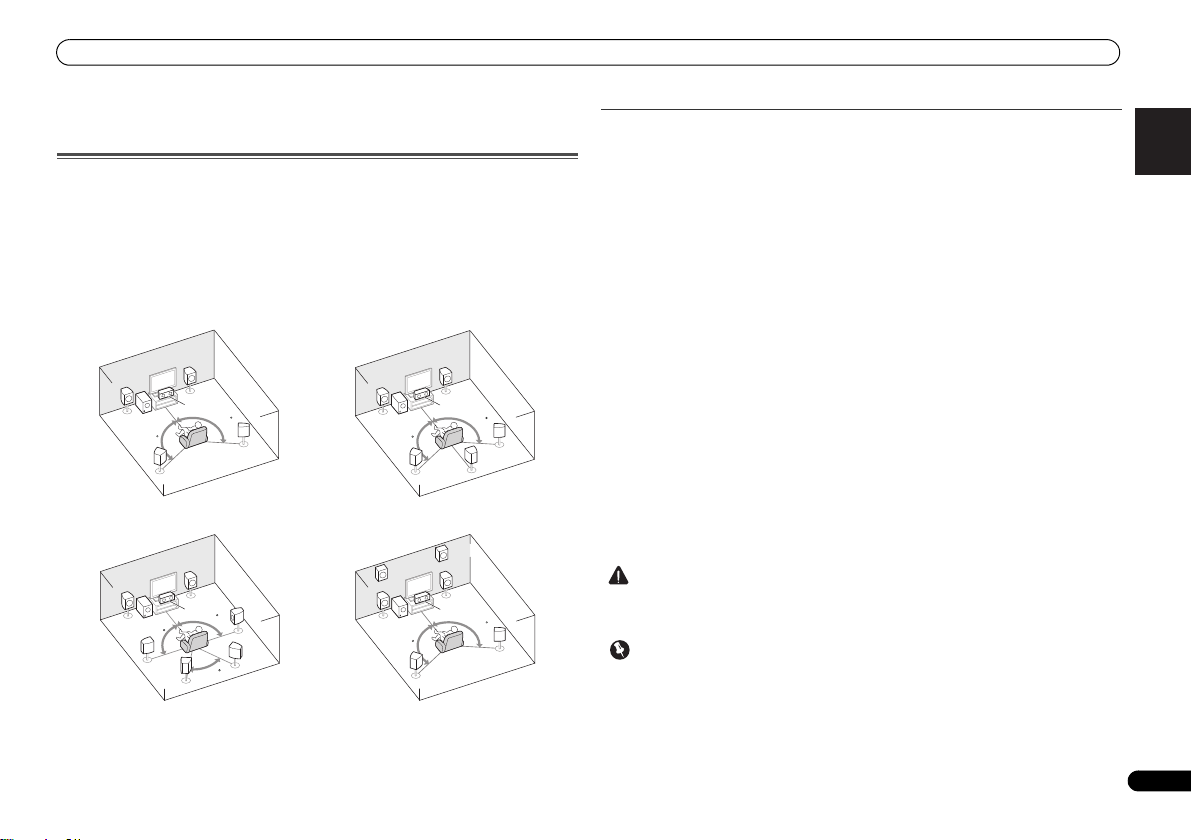
5.1 channel surround system:
7.1 channel surround
(Surround back) system:
a
7.1 channel surround
(Front height) system:
a
6.1 channel surround
(Surround back) system:
a
Connecting your equipment
Placing the speakers
By connecting the left and right front speakers (L/R), the center speaker (C), the left and right
surround speakers (
Further, by using an external amplifier, you can connect the left and right surround back
speakers (SBL/SBR) or the left and right front height speaker (FHL/FHR) to boost your system
up to a 7.1 ch surround system.
• You can also connect one surr ound back speaker (SB) and enjoy a 6.1 ch surround system.
To achieve the best possible surround sound, install your speakers as shown below.
a. This layout is available only when the additional amplifier is connected to the unit and the
surround back or front height speakers are connected to the amplifier. For details, see Connect
the surround back or front height speakers on page 8.
SL/SR
), and the subwoofer (SW), a 5.1 ch surround system can be enjoyed.
Hints on the speaker placement
Where you put your speakers in the room has a big effect on the quality of the sound. The
following guidelines should help you to get the best sound from your system.
• The subwoofer can be placed on the floor. Ideally, the other speakers should be at about
ear-level when you’re listening to them. Putting the speakers on the floor (except the
subwoofer), or mounting them very high on a wall is not recommended.
• For the best stereo effect, place the front speakers 2 m to 3 m apart, at equal distance from
the TV.
• If you’re going to place speakers around your CRT TV, use shielded speakers or place the
speakers at a sufficient distance from your CRT TV.
• If you’re using a center speaker, place the front speakers at a wider angle. If not, place
them at a narrower angle.
• Place the center speaker above or below the TV so that the sound of the center channel is
localized at the TV screen. Also, make sure the center speaker does not cross the line
formed by the leading edge of the front left and right speakers.
• It is best to angle the speakers towards the listening position. The angle depends on the
size of the room. Use less of an angle for bigger rooms.
• Surround and surround back speakers should be positioned 60 cm to 90 cm higher than
your ears and titled slight downward. Make sure the speakers don’t face each other. For
DVD-Audio, the speakers should be more directly behind the listener than for home
theater playback.
• If the surround speakers cannot be set directly to the side of the listening position with a
7.1-channel system, the surround effect can be enhanced by turning off the Up Mix
function (see Setting the Up Mix function on Operating Instructions in CD-ROM).
• Try not to place the surround speakers farther away from the listening position than the
front and center speakers. Doing so can weaken the surround sound effect.
• Place the left and right front height speakers at least one meter directly above the left and
right front speakers.
• Make sure that all speakers are securely installed. This not only improves sound quality,
but also reduces the risk of damage or injury resulting from speakers being knocked over
or falling in the event of external shocks such as earthquakes.
• To connect the sur round back or front height speakers, an additional amplifier is required.
Connect the additional amplifier to the PRE OUT SURR BACK/FRONT HEIGHT outputs of
this unit and connect the surround back or front height speakers to the additional amplifier
(see Connect the surround back or front height speakers on page 8).
7
En
Page 8
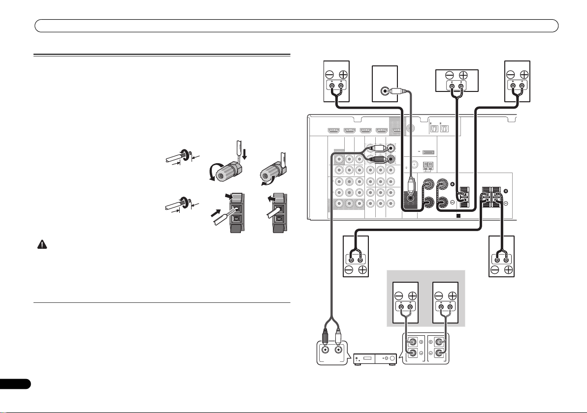
Connecting your equipment
CAUTION
12 3
10 mm
12 3
10 mm
LINE LEVEL
INPUT
ANALOG
RL
AUDIO IN
SPEAKER R SPEAKER L
Center
Surround right
Front right
Surround back or front height
channel amplifier
Front left
Subwoofer
Surround left
Right
Left
Surround back or
front height speakers
Connecting the speakers
The receiver will work with just two stereo speakers (the front speakers in the diagram) but
using at least three speakers is recommended, and a complete setup is best for surround
sound.
Make sure you connect the speaker on the right to the right (R) terminal and the speaker on
the left to the left (L) terminal. Also make sure the positive and negative (+/–) terminals on the
receiver match those on the speakers.
Be sure to complete all connections before connecting this unit to the AC power source.
Bare wire connections
Front speaker terminals:
1
2
3
Center and surround speaker terminals:
1
2
wire.
3
Connect the surround back or front height speakers
Connect the PRE OUT SURR BACK/FRONT HEIGHT outputs of the unit and additional
amplifier to add a surround back or front height speaker.
8
En
Twist exposed wire strands together.
Loosen terminal and insert exposed wire.
Tighten terminal.
Twist exposed wire strands together.
Push open the tabs and insert exposed
Release the tabs.
• These speaker terminals carry HAZARDOUS LIVE voltage. To prevent the risk of electric
shock when connecting or disconnecting the speaker cables, disconnect the power cord
before touching any uninsulated parts.
• Make sure that all the bare speaker wire is twisted together and inserted fully into the
speaker terminal. If any of the bare speaker wire touches the back panel it may cause the
power to cut off as a safety measure.
• The Pre Out setting must be set if the above connections are performed. Select
SURR.BACK if the surround back speaker is connected and HEIGHT if the front height
speaker is connected (If neither the surround back speaker nor the front height speaker is
connected, either setting will suffice) (see The Pre Out Setting on Operating Instructions in
CD-ROM).
• You can use the additional amplifier on the surround back channel pre-outs for a single
speaker as well. In this case plug the amplifier into the left (L (Single)) terminal only.
HDMI
DVR/BDR IN
VIDEO
MONITOR
OUT
DVR/
BDR
OUTINDVD IN
1
IN
(
)
DVD
ASSIGNABLE
2
IN
(
DVR/
)
BDR
MONITOR
OUT
YP
COMPONENT VIDEO
DVD IN
TV/SATINBD
B PR
BD IN VIDEO IN
AUDIO
DVR/BDR
IN
OUT
IN IN
IN
TV/SAT
CD-R/TAPE
BD
OUT
SURR BACK/
FRONT HEIGHT
(
Single
PRE OUT
CD
IN
DVD
L
R
L
R
L
R
)
(
OUTPUT 5 V
0.1 A MAX
FM
UNBAL
75
SUBWOOFER
PRE OUT
COAXIAL
1
IN
(CD)
ADAPTER PORT
)
AM LOOP
ASSIGNABLE
ANTENNA
OPTICAL
IN
IN
1
2
(
)
(
TV/SAT
CD-R/TAPE
FRONT
RL
SPEAKERS
ASSIGNABLE
)
A
CENTER
SURROUND
RL
Page 9
Connecting your equipment
English
Français
Italiano
Español
Nederlands
Deutsch
Important
Note
Note
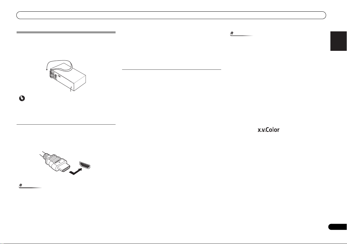
Making cable connections
Make sure not to bend the cables over the top of this unit (as
shown in the illustration). If this happens, the magnetic field
produced by the transformers in this unit may cause a
humming noise from the speakers.
• Before making or changing connections, switch off the
power and disconnect the power cord from the AC outlet.
• Before unplugging the power cord, switch the power into
standby.
HDMI cables
Both video and sound signals can be transmitted
simultaneously with one cable. If connecting the player and
the TV via this receiver, for both connections, use HDMI
cables.
HDMI
Be careful to connect the terminal in the proper direction.
• Set the HDMI parameter to THRU (THROUGH) and set
the input signal to HDMI, if you want to hear HDMI audio
output from your TV (no sound will be heard from this
receiver) (see Setting the Audio options and Selecting the
audio input signal on Operating Instructions in CD-ROM).
• If the video signal does not appear on your TV, try
adjusting the resolution settings on your component or
di sp la y. Not e t ha t s ome co mp on en ts ( su ch as vid eo ga me
units) have resolutions that may not be displayed. In this
case, use a (analog) composite connection.
• When the video signal from the HDMI is 480i, 480p, 576i
or 576p, Multi Ch PCM sound and HD sound cannot be
received.
About HDMI
The HDMI connection transfers uncompressed digital video,
as well as almost every kind of digital audio that the
connected component is compatible with, including DVDVideo, DVD-Audio, SACD, Dolby Digital Plus, Dolby TrueHD,
DTS-HD Master Audio (see below for limitations), Video CD/
Super VCD and CD.
This receiver incorporates High-Definition Multimedia
Interface (HDMI
This receiver supports the functions described below through
HDMI connections.
• Digital transfer of uncompressed video (contents
protected by HDCP (1080p/24, 1080p/60, etc.))
• 3D signal transfer
• Deep Color signal transfer
• x.v.Color signal transfer
• Audio Return Channel
• Input of multi-channel linear PCM digital audio signals
(192 kHz or less) for up to 8 channels
• Input of the following digital audio formats:
– Dolby Digital, Dolby Digital Plus, DTS, High bitrate
audio (Dolby TrueHD, DTS-HD Master Audio), DVDAudio, CD, SACD (DSD 2 ch only), Video CD, Super VCD
• Synchronized operation with components using the
Control with HDMI function (see Control with HDMI
function on Operating Instructions in CD-ROM)
®
) technology.
• Use a High Speed HDMI® cable. If HDMI cable other than
a High Speed HDMI
properly.
• When an HDMI cable with a built-in equalizer is
connected, it may not operate properly.
• 3D, Deep Color, x.v.Color signal transfer and Audio
Return Channel are only possible when connected to a
compatible component.
• HDMI format digital audio transmissions require a longer
time to be recognized. Due to this, interruption in the
audio may occur when switching between audio formats
or beginning playback.
• Turning on/off the device connected to this unit’s HDMI
OUT terminal during playback, or disconnecting/
connecting the HDMI cable during playback, may cause
noise or interrupted audio.
HDMI, the HDMI Logo and High-Definition Multimedia
Interface are trademarks or registered trademarks of HDMI
Licensing, LLC in the United States and other countries.
“x.v.Color” and are trademarks of Sony
Corporation.
®
cable is used, it may not work
9
En
Page 10
Connecting your equipment
Note
White (Left)
Red (Right)
COAXIAL
IN
OPTICAL
IN
Coaxial digital
audio cable
Optical cable
VIDEO
Yellow
Green (Y)
Red (PR)
Blue (PB)
Terminal for connection with source device
Terminal for connection with TV monitor
Playback
component
TV
The OSD will
not appear.
Video signals can be output.
Analog audio cables
Use stereo RCA phono cables to connect analog audio
components. These cables are typically red and white, and
you should connect the red plugs to R (right) terminals and
white plugs to L (left) terminals.
L
AUDIO
R
Digital audio cables
Commercially available coaxial digital audio cables or optical
cables should be used to connect digital components to this
receiver.
• When connecting optical cables, be careful when
inserting the plug not to damage the shutter protecting
the optical socket.
• When storing optical cable, co il loosely. The cable may be
damaged if bent around sharp corners.
• You can also use a standard RCA video cable for coaxial
digital connections.
Video cables
Standard RCA video cables
These cables are the most common type of video connection
and are used to connect to the composite video terminals.
The yellow plugs distinguish them from cables for audio.
Component video cables
Use component video cables to get the best possible color
reproduction of your video source. The color signal of the TV
is divided into the luminance (Y) signal and the color (P
P
R) signals and then output. In this way, interference between
the signals is avoided.
COMPONENT VIDEO
Y
P
B
B and
P
R
About video outputs connection
This receiver is not loaded with a video converter. When you
use component video cables or HDMI cables for connecting
to the input device, the same cables should be used for
connecting to the TV.
The signals input from the analog (composite and
component) video inputs of this unit will not be output from
the HDMI OUT.
IN
HDMI
OUT
HDMI
IN
YPBP
COMPONENT VIDEO
MONITOR
OUT
YPBP
COMPONENT VIDEO
R
R
IN
VIDEO
MONITOR
OUT
VIDEO
10
En
Page 11
Connecting your equipment
English
Français
Italiano
Español
Nederlands
Deutsch
Important
VIDEO
MONITOR
OUT
N
VIDEO IN
HDMI IN
HDMI OUT
RL
DIGITAL AUDIO OUTANALOG AUDIO OUT
OPTICAL
Select one
HDMI/DVI-compatible TV
HDMI/DVI-compatible
Blu-ray Disc player
This connection is
necessary in order to
see the OSD of the
unit on the TV.
If the TV does not support
the HDMI Audio Return
Channel function, this
connection is required to
listen to the TV sound over
the receiver.
Connecting a TV and playback components
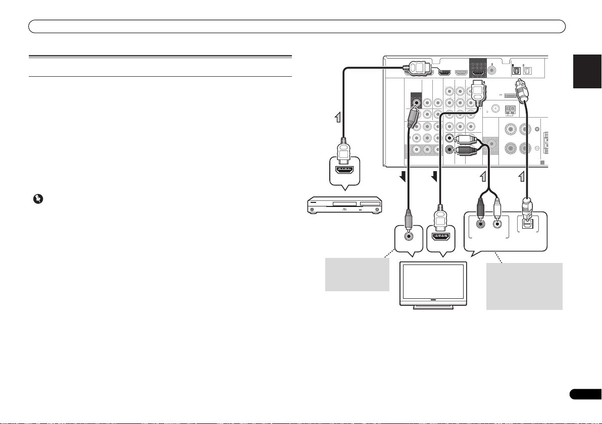
Connecting using HDMI
If you have an HDMI or DVI (with HDCP) equipped component (Blu-ray Disc player, etc.), you
can connect it to this receiver using a commercially available HDMI cable.
If the TV and playback components support the Control with HDMI feature, the convenient
Control with HDMI functions can be used (see Control with HDMI function on Operating
Instructions in CD-ROM).
• The following connection/setting is required to listen to the sound of the TV over this
receiver.
-
If the TV does not support the HDMI Audio Return Channel function, connect the receiver
and TV with audio cables (as shown).
-
If the TV supports the HDMI Audio Return Channel function, the sound of the TV is input
to the receiver via the HDMI terminal, so there is no need to connect an audio cable. In
this case, set ARC at HDMI Setup to ON (see HDMI Setup on Operating Instructions in
CD-ROM).
• If the receiver is connected to a TV using an HDMI cable, the on-screen display (OSD) will
not be displayed. Be sure to use a standard RCA analog video cable to connect. In this
case, switch the TV input to analog to see the OSD screen (for setup, etc.) on the TV.
• When the Control with HDMI function is ON and the receiver is connected to a compatible
TV with an HDMI cable, and you switch the input of the TV to composite or component, the
input of the receiver may automatically switch to TV/SAT. If this happens, switch the
receiver’s input back to the original input, or turn OFF the Control with HDMI function (see
HDMI Setup on Operating Instructions in CD-ROM).
HDMI
DVR/BDR IN
VIDEO
MONITOR
OUT
DVR/
BDR
OUTINDVD IN
1
IN
(
)
DVD
ASSIGNABLE
2
IN
(
DVR/
)
BDR
MONITOR
OUT
YP
COMPONENT VIDEO
DVD IN
TV/SATINBD
BPR
BD IN VIDEO IN
AUDIO
DVR/BDR
IN
OUT
IN IN
IN
TV/SAT
CD-R/TAPE
BD
OUT
SURR BACK/
FRONT HEIGHT
L
(
Single
PRE OUT
R
CD
L
R
L
IN
R
DVD
COAXIAL
)
(
OUTPUT 5 V
0.1 A MAX
FM
UNBAL
75
SUBWOOFER
PRE OUT
1
IN
(CD)
ADAPTER PORT
)
AM LOOP
ASSIGNABLE
ANTENNA
OPTICAL
IN
IN
1
2
(
)
(
TV/SAT
CD-R/TAPE
FRONT
RL
SPEAKERS
ASSIGNABLE
)
CE
A
11
En
Page 12
Connecting your equipment
Note
Note
T
RL
DIGITAL AUDIO OUT ANALOG AUDIO OUT
OPTICAL
RL
DIGITAL AUDIO OUTANALOG AUDIO OUT
OPTICAL COAXIAL
VIDEO IN
VIDEO OUT
Select one
TV
DVD player
Select one
This connection is
required in order to
listen to the sound of
the TV over the
receiver.
T
RL
DIGITAL AUDIO OUTANALOG AUDIO OUT
OPTICALCOAXIAL
VIDEO OUT
Select one
Set-top box, etc.
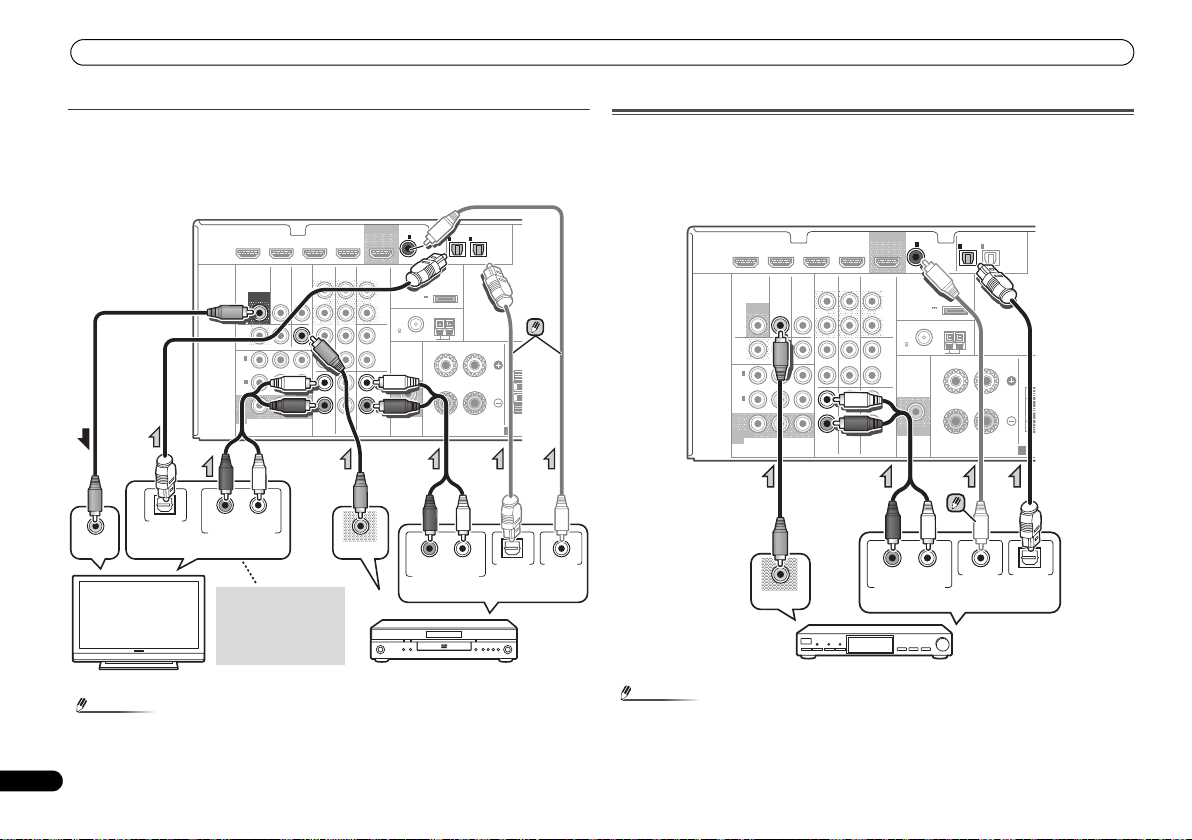
Connecting your component with no HDMI terminal
This diagram shows connections of a TV and DVD player (or other playback component) with
no HDMI terminal to the receiver.
• If both TV and player has a component video jacks, you can connect these too. See Using
the component video jacks on page 13 for more on this.
COAXIAL
CD-R/TAPE
SURR BACK/
FRONT HEIGHT
BD
OUT
(
PRE OUT
CD
IN
DVD
IN
(CD)
L
)
Single
(
OUTPUT 5 V
0.1 A MAX
R
FM
UNBAL
75
L
R
L
R
SUBWOOFER
PRE OUT
IN
1
1
ASSIGNABLE
(
ADAPTER PORT
)
ANTENNA
AM LOOP
RL
TV/SAT
FRONT
• In order to listen to the audio from the DVD player that is connected to this receiver using
12
En
DVD IN
HDMI
DVR/BDR IN
VIDEO
DVR/
BDR
1
IN
(
DVD
ASSIGNABLE
2
IN
(
DVR/
BDR
MONITOR
OUT
MONITOR
TV/SATINBD
OUT
OUTINDVD IN
)
)
BPR
YP
COMPONENT VIDEO
BD IN VIDEO IN
AUDIO
DVR/BDR
IN
OUT
IN IN
IN
TV/SAT
an optical cable or a coaxial cable, first, switch to the DVD input, then press SIGNAL SEL
to choose the audio signal O2 (OPTICAL2) or C1 (COAXIAL1).
IN
2
)
(
CD-R/TAPE
SPEAKERS
OPTICAL
ASSIGNABLE
)
Connecting a satellite receiver or other digital set-top box
Satellite and cable receivers, and terrestrial digital TV tuners are all examples of so-called ‘settop boxes’.
• If the set-top box or video component also has an HDMI or a component video output, you
can connect this too. See Connecting using HDMI on page 11 or Using the component
video jacks on page 13 for more on this.
COAXIAL
CD-R/TAPE
BD
OUT
SURR BACK/
FRONT HEIGHT
L
(
Single
PRE OUT
R
CD
L
R
L
IN
R
DVD
)
(
OUTPUT 5 V
0.1 A MAX
FM
UNBAL
75
SUBWOOFER
PRE OUT
1
IN
(CD)
ADAPTER PORT
)
AM LOOP
ASSIGNABLE
ANTENNA
OPTICAL
IN
IN
1
2
ASSIGNABLE
(
)
(
TV/SAT
CD-R/TAPE
FRONT
RL
SPEAKERS
)
CEN
A
DVD IN
DVR/BDR IN
HDMI
VIDEO
MONITOR
DVR/
CEN
A
• In o rder to listen to the audio from the source component that is connected to this receiver
using a coaxial cable, first, switch to the TV/SAT, then press SIGNAL SEL to choose the
audio signal C1 (COAXIAL1).
BDR
1
IN
(
)
DVD
ASSIGNABLE
2
IN
(
DVR/
)
BDR
MONITOR
OUT
COMPONENT VIDEO
TV/SATINBD
OUT
OUTINDVD IN
YP
BPR
BD IN VIDEO IN
AUDIO
DVR/BDR
IN
OUT
IN IN
IN
TV/SAT
Page 13
Connecting your equipment
English
Français
Italiano
Español
Nederlands
Deutsch
Note
Important
T
Select one
HDD/DVD recorder, Blu-ray
Disc recorder, etc.
C
FRONT HEIGHT
Y
P
B
PR
COMPONENT VIDEO IN
Y
P
B
PR
COMPONENT VIDEO OUT
DVD player
TV
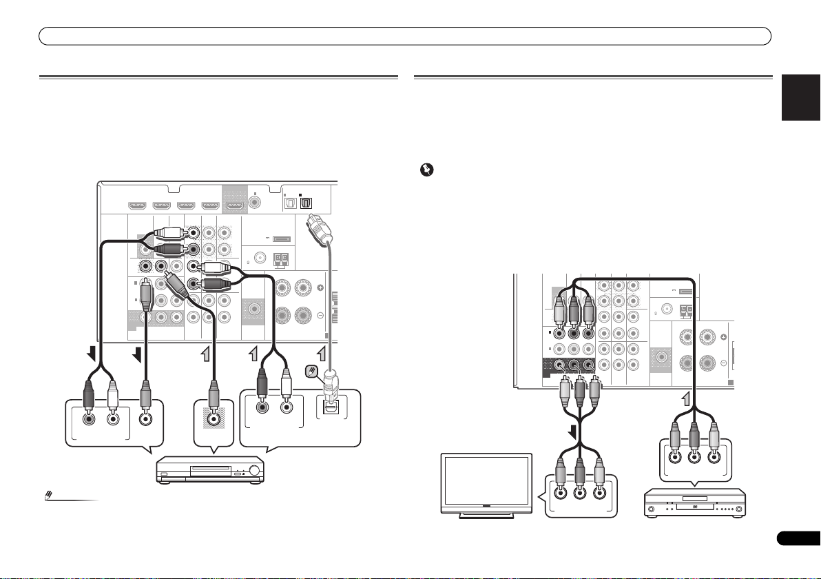
Connecting an HDD/DVD recorder, Blu-ray Disc recorder and other
video sources
This receiver has audio/video inputs and outputs suitable for connecting analog or digital
video recorders, including HDD/DVD recorders and Blu-ray Disc recorders.
• Only the signals that are input to the VIDEO IN terminal can be output from the VIDEO OUT
terminal.
• Audio signals that are input through the digital term inal will not be output from the analog
terminal.
COAXIAL
HDMI
RL
ANALOG AUDIO IN
DVR/BDR IN
VIDEO
MONITOR
OUT
DVD IN
MONITOR
TV/SATINBD
OUT
DVR/
BDR
OUTINDVD IN
1
IN
(
)
DVD
ASSIGNABLE
2
IN
(
DVR/
)
BDR
YP
COMPONENT VIDEO
VIDEO IN
IN
BPR
BD IN VIDEO IN
AUDIO
DVR/BDR
OUT
IN IN
IN
TV/SAT
CD-R/TAPE
BD
VIDEO OUT
OUT
SURR BACK/
FRONT HEIGHT
L
(
Single
PRE OUT
R
CD
L
R
L
IN
R
DVD
IN
(CD)
)
(
OUTPUT 5 V
0.1 A MAX
FM
UNBAL
75
SUBWOOFER
PRE OUT
1
ASSIGNABLE
ADAPTER PORT
)
ANTENNA
AM LOOP
RL
OPTICAL
IN
IN
1
2
ASSIGNABLE
(
)
(
TV/SAT
CD-R/TAPE
FRONT
RL
SPEAKERS
DIGITAL AUDIO OUTANALOG AUDIO OUT
)
CEN
A
OPTICAL
Using the component video jacks
Component video should deliver superior picture quality when compared to composite video.
A further advantage (if your source and TV are both compatible) is progressive-scan video,
which delivers a very stable, flicker-free picture. See the manuals that came with your TV and
source component to check whether they are compatible with progressive-scan video.
• For the audio connection, refer to Connecting your component with no HDMI terminal on
page 12.
• If you connect any source component to the receiver using a component video input, you
must also have your TV connected to this receiver’s COMPONENT VIDEO MONITOR OUT
jacks.
• If necessary, assign the component video inputs to the input source you’ve connected.
This only needs to be done if you didn’t connect according to the following defaults:
-
COMPONENT VIDEO IN 1: DVD
-
COMPONENT VIDEO IN 2: DVR/BDR
See The Input Assign menu on Operating Instructions in CD-ROM for more on this.
MONITOR
OUT
DVR/
BDR
OUTINDVD IN
1
IN
(
)
DVD
ASSIGNABLE
2
IN
(
DVR/
)
BDR
MONITOR
OUT
COMPONENT VIDEO
TV/SATINBD
B PR
YP
DVR/BDR
IN
OUT
IN IN
IN
TV/SAT
D-R/TAPE
ADAPTER PORT
L
(
)
Single
(
OUTPUT 5 V
)
PRE OUT
0.1 A MAX
R
ANTENNA
FM
UNBAL
CD
75
L
AM LOOP
FRONT
R
L
IN
R
DVD
BD
RL
SUBWOOFER
PRE OUT
SPEAKERS
C
A
• In order t o listen to the audio from the source component that is connected to this receiver
using an optical cable, first, switch to the DVR/BDR input, then press SIGNAL SEL to
choose the audio signal O2 (OPTICAL2).
13
En
Page 14
Connecting your equipment
Note
N
Select one
CD-R, MD, DAT,
Tape recorder, etc.
fig. a
fig. b
One-touch
PAL connector
75 Ω coaxial cable
ANTENNA
AM LOOP
Outdoor
antenna
5 m to 6 m
Indoor antenna
(vinyl-coated wire)
Connecting other audio components
The number and kind of connections depends on the kind of
component you’re connecting. Follow the steps below to
connect a CD-R, MD, DAT, tape recorder or other audio
component.
• Note that you must connect digital components to analog
• In order to listen to the audio from the CD player that is
14
En
audio jacks if you want to record to/from digital
components (like an MD) to/from analog components.
COAXIAL
CD-R/TAPE
SURR BACK/
FRONT HEIGHT
DVD
BD
RL
OUT
PRE OUT
CD
L
(
Single
R
L
R
L
IN
R
IN
(CD)
)
(
OUTPUT 5 V
0.1 A MAX
FM
UNBAL
75
SUBWOOFER
PRE OUT
1
ASSIGNABLE
ADAPTER PORT
)
ANTENNA
AM LOOP
DIGITAL AUDIO OUTANALOG AUDIO OUT
IN
IN
1
2
(
)
(
TV/SAT
CD-R/TAPE
FRONT
RL
SPEAKERS
OPTICALCOAXIAL
OPTICAL
HDMI
DVR/BDR IN
VIDEO
MONITOR
DVR/
BDR
1
IN
(
)
DVD
ASSIGNABLE
2
IN
(
DVR/
)
BDR
MONITOR
OUT
COMPONENT VIDEO
TV/SATINBD
OUT
OUTINDVD IN
YP
B PR
BD IN VIDEO IN
AUDIO
DVR/BDR
IN
OUT
IN IN
IN
TV/SAT
DVD IN
RL
REC
ANALOG AUDIO IN
connected to this receiver using a coaxial cable, first,
switch to the CD-R input, then press SIGNAL SEL to
choose the audio signal C1 (COAXIAL1).
ASSIGNABLE
)
Connecting antennas
Connect the AM loop antenna and the FM wire antenna as
shown below. To improve reception and sound quality,
connect external antennas (see Using external antennas
below).
4
CE
A
1
1
Push open the tabs, then insert one wire fully into each
terminal, then release the tabs to secure the AM antenna
wires.
2
Fix the AM loop antenna to the attached stand.
To fix the stand to the antenna, bend in the direction
indicated by the arrow (fig. a) then clip the loop onto the
stand (fig. b).
3
Place the AM antenna on a flat surface and in a direction
giving the best reception.
4
Connect the FM wire antenna into the FM antenna
socket.
For best results, extend the FM antenna fully and fix to a wall
or door frame. Don’t drape loosely or leave coiled up.
FM
UNBAL
75
ANTENNA
AM LOOP
Using external antennas
To improve FM reception
Use a PAL connector (not supplied) to connect an external
FM antenna.
ANTENNA
FM
UNBAL
2
3
75
To improve AM reception
Connect a 5 m to 6 m length of vinyl-coated wire to the AM
antenna terminal without disconnecting the supplied AM
loop antenna.
For the best possible reception, suspend horizontally
outdoors.
Page 15

Connecting your equipment
English
Français
Italiano
Español
Nederlands
Deutsch
CAUTION
Note
Plugging in the receiver
Only plug in after you have connected all your components to
this receiver, including the speakers.
• Handle the power cord by the plug part. Do not pull out
the plug by tugging the cord, and never touch the power
cord when your hands are wet, as this could cause a short
circuit or electric shock. Do not place the unit, a piece of
furniture, or other object on the power cord or pinch the
cord in any other way. Never make a knot in the cord or tie
it with other cables. The power cords should be routed so
that they are not likely to be stepped on. A damaged
power cord can cause a fire or give you an electric shock.
Check the power cord once in a while. If you find it
damaged, ask your nearest Pioneer authorized
independent service company for a replacement.
• Do not use any power cord other than the one supplied
with this unit.
• Do not use the supplied power cord for any purpose other
than that described below.
• The receiver should be disconnected by removing the
mains plug from the wall socket when not in regular use,
e.g., when on vacation.
• After this receiver is connected to an AC outlet, a 2
second to 10 second HDMI initialization process begins.
You cannot carry out any operations during this process.
The HDMI indicator in the front panel display blinks
during this process, and you can turn on this receiver
once it has stopped blinking. When you set the Control
with HDMI to OFF, you can skip this process. For details
about the Control with HDMI feature, see Control with
HDMI function on Operating Instructions in CD-ROM.
1
Plug the supplied power cord into the AC IN socket on
the back of the receiver.
2
Plug the other end into a power outlet.
15
En
Page 16
CAUTION
Important
INPUT SELECT
SOURCESLEEP
TV
CONTROL
INPUT
RECEIVER
RECEIVER
BD DVD TV
DTV/TV
ENTER
MUTE
RETURN
PARAMETER
TOOLS
VOLUME
BAND
MENU
TOP
MENU
T
U
N
E
T
U
N
E
P
R
E
S
E
T
P
R
E
S
E
T
HOME
MENU
SETUP
PTY SEARCH
MASTER
VOLUME
SOUND
RETRIEVER
PORTABLE /
MCACC
SETUP MIC
PRESET ENTER
Tripod
Microphone
RECEIVER
System Setup
1.Auto MCACC
2.Manual SP Setup
3.Input Assign
4.Pre Out Setting
5.HDMI Setup
6.Auto Power Down
7.FL Demo Mode
Return
16
En
Basic Setup
Basic Setup
Canceling the demo display
The display on the front panel shows various information
(demo displays) when the receiver is not operating.
You can turn off the demo display. For details, see The FL
Demo Mode menu on Operating Instructions in CD-ROM.
• The demo mode is canceled automatically when the Auto
MCACC setup is performed (see below).
Automatically setting up for surround sound
(MCACC)
The Auto Multi-Channel Acoustic Calibration (MCACC) setup
measures the acoustic characteristics of your listening area,
taking into account ambient noise, speaker size and
distance, and tests for both channel delay and channel level.
After you have set up the microphone provided with your
system, the receiver uses the information from a series of test
tones to optimize the speaker settings and equalization for
your particular room.
• The test tones used in the Auto MCACC setup are output
at high volume.
• The OSD will not appear if you have connected using the
HDMI output to your TV. Use composite or component
connections for system setup.
• The Auto MCACC setup will overwrite any existing
speaker settings you’ve made.
• If you connected either the surround back speaker or the
front height speaker, make sure that the Pre Out setting
is correctly set before performing the Auto MCACC setup
(see The Pre Out Setting on Operating Instructions in CDROM). (Here is an explanation using the OSD screen for
a surround back speaker connection.)
1
Switch on the receiver and your TV.
2
Switch the TV input to the input that connects this
receiver to the TV through the corresponding composite or
component cable.
3
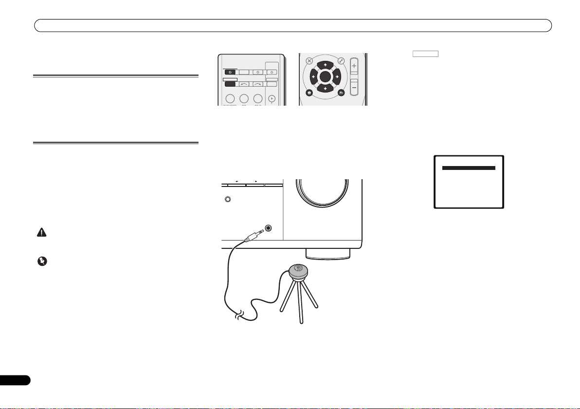
Connect the microphone to the MCACC SETUP MIC jack
on the front panel.
Make sure there are no obstacles between the speakers and
the microphone.
If you have a tripod, use it to place the microphone so that it’s
about ear level at your normal listening position. Otherwise,
place the microphone at ear level using a table or a chair.
4
Press on the remote control, then press the
SETUP button.
The System Setup menu appears on your TV. Use ///
and ENTER on the remote control to navigate through the
screens and select menu items. Press RETURN to exit the
current menu.
•Press SETUP at any time to exit the System Setup menu.
If you cancel the Auto MCACC setup at any time, the
receiver automatically exits and no settings will be made.
• The screensaver automatically starts after three minutes
of inactivity.
5
Select ‘Auto MCACC’ from the System Setup menu, then
press ENTER.
• MIC IN blinks when the microphone is not connected to
MCACC SETUP MIC jack.
Try to be as quiet as possible after pressing ENTER. The
system outputs a series of test tones to establish the ambient
noise level.
6
Follow the instructions on-screen.
• Make sure the microphone is connected.
• Make sure the subwoofer is on and the volume is turned
up.
• When using surround back or front height speakers, turn
on the power to the amplifier to which the surround back
or front height speakers are connected, and adjust the
sound level to the desired level.
• See below for notes regarding background noise and
other possible interference.
Page 17
Basic Setup
English
Français
Italiano
Español
Nederlands
Deutsch
Note
1.Auto MCACC
Now Analyzing
Environment Check
Ambient Noise
Speaker YES/NO
Return
1.Auto MCACC
Now Analyzing
Surround Analyzing
Speaker System
Speaker Distance
Channel Level
Acoustic Cal EQ
Return
7
Wait for the test tones to finish.
A progress report is displayed on-screen while the receiver
outputs test tones to determine the speakers present in your
setup. Try to be as quiet as possible while it’s doing this.
• For correct speaker settings, do not adjust the volume
during the test tones.
8
Confirm the speaker configuration.
The configuration shown on-screen should reflect the actual
speakers you have.
1.Auto MCACC
Check!
[ YES ]
Front
[ YES ]
Center
[ YES ]
Surr
[YESx2]
Surr. Back
[ YES ]
Subwoofer
10:Next
• With error messages (such as Too much ambient noise)
select RETRY after checking for ambient noise (see Other
problems when using the Auto MCACC setup below).
If the speaker configuration displayed isn’t correct, use /
to select the speaker and / to change the setting. When
you’re finished, go to the next step.
If you see an error message (ERR) in the right side column,
there may be a problem with the speaker connection. If
selecting RETRY doesn’t fix the problem, turn off the power
and check the speaker connections.
OK
Return
9
Make sure ‘OK’ is selected, then press ENTER.
If the screen in step 7 is left untouched for 10 seconds and
ENTER is not pressed in step 8, the Auto MCACC setup will
start automatically as shown.
A progress report is displayed on-screen while the receiver
outputs more test tones to determine the optimum receiver
settings for channel level, speaker distance, and Acoustic
Calibration EQ.
Again, try to be as quiet as possible while this is happening.
It may take 1 to 3 minutes.
10
The Auto MCACC setup has finished! You return to the
System Setup menu.
The settings made in the Auto MCACC setup should give you
excellent surround sound from your system, but it is also
possible to adjust these settings manually using the System
Setup menu (see The System Setup menu on Operating
Instructions in CD-ROM).
• Depending on the characteristics of your room,
sometimes identical speakers with cone sizes of around
12 cm will end up with different size settings. You can
correct the setting manually using the Speaker Setting on
Operating Instructions in CD-ROM to do this.
• The subwoofer distance setting may be farther than the
actual distance from the listening position. This setting
should be accurate (taking delay and room
characteristics into account) and generally does not need
to be changed.
Other problems when using the Auto MCACC
setup
If the room environment is not optimal for the Auto MCACC
setup (too much background noise, echo off the walls,
obstacles blocking the speakers from the microphone) the
final settings may be incorrect. Check for household
appliances (air conditioner, fridge, fan, etc.), that may be
affecting the environment and switch them off if necessary.
If there are any instructions showing in the front panel
display, please follow them.
• Some older TVs may interfere with the operation of the
microphone. If this seems to be happening, switch off the
TV when doing the Auto MCACC setup.
17
En
Page 18
Basic playback
Note
INPUT SELECT
SOURCESLEEP
TV
CONTROL
INPUT
RECEIVER
CH
VOL
RECEIVER
BD DVD TV
DVR/BDRCDCD-R
ADAPTER
TUNER
PORTABLE
VIDEO
SIGNAL SELS.RETRIEVER
DTV/TV
ENTER
ADV SURR
AUTO/
DIRECT
MUTE
RETURN
AUDIO
PARAMETER
TUNER EDIT
TOOLS
MASTER
VOLUME
BAND
MENU
TRE
BASS
TOP
MENU
T
U
N
E
T
U
N
E
P
R
E
S
E
T
P
R
E
S
E
T
BD MENU
HOME
MENU
SETUP
PTY SEARCH
ALC/
STANDARD
STEREO
RECEIVER
ADV SURR
AUTO/
DIRECT
AUDIO
PARAMETER
TUNER EDIT
TOOLS
MASTER
VOLUME
BD MENU
ALC/
STANDARD
STEREO
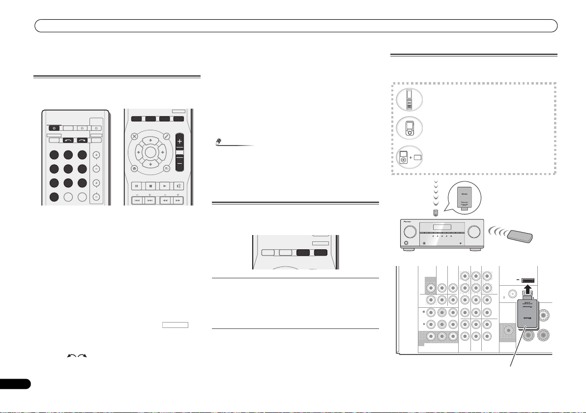
Bluetooth wireless technology enabled device:
cell phone
Bluetooth wireless technology enabled device:
Digital music player
Device not equipped with Bluetooth wireless
technology: Digital music player + Bluetooth
audio transmitter (sold commercially)
Music data
Remote control
operation
This receiver
Bluetooth® ADAPTER
AS-BT100 or AS-BT200
(sold separately)
VIDEO
COMPONENT VIDEO
DVR/
BDR
L
R
R
L
YP
BPR
PRE OUT
SPEAKE
ANTENNA
ASSIGNABLE
DVR/BDR
OUT
CD-R/TAPE
SURR BACK/
FRONT HEIGHT
L
R
PRE OUT
(
Single
)
SUBWOOFER
IN IN
CD
MONITOR
OUT
TV/SATINBD
IN
OUTINDVD IN
IN
TV/SAT
BD
IN
DVD
(
DVD
)
IN
1
MONITOR
OUT
(
DVR/
BDR
)
IN
2
FM
UNBAL
75
(
OUTPUT 5 V
0.1 A MAX
)
ADAPTER PORT
AM LOOP
FRONT
RL
Bluetooth® ADAPTER
18
En
Basic playback
Playing a source
Here are the basic instructions for playing a source (such as
a DVD disc) with your home theater system.
1
Switch on your system components and receiver.
Start by switching on the playback component (for example a
DVD player), your TV and subwoofer (if you have one), then
the receiver (press RECEIVER).
• Make sure the setup microphone is disconnected.
2
Switch the TV input to the input that connects this
receiver.
For example, if you connected this receiver to the VIDEO
jacks on your TV, make sure that the VIDEO input is now
selected.
3
Press input function buttons to select the input function
you want to play.
• The input of the receiver will switch over, and you will be
able to operate other components using the remote
control. To operate the receiver, first press on
the remote control, then press the appropriate button to
operate.
• The input source can also be selected by using INPUT
SELECT buttons on the remote control, or by
using the front panel INPUT SELECTOR dial. In this case,
the remote control won’t switch operational modes.
If you selected the proper input source and there is still no
sound, press SIGNAL SEL to select the audio input signal for
playback.
4
Press AUTO/DIRECT to select ‘AUTO SURROUND’ and
start playback of the source.
If you’re playing a Dolby Digital or DTS surround sound DVD
disc, with a digital audio connection, you should hear
surround sound. If you’re playing a stereo source or if the
connection is an analog audio connection, you will only hear
sound from the front left/right speakers in the default
listening mode.
• You may need to check the digital audio output settings
on your DVD player or digital satellite receiver. It should
be set to output Dolby Digital, DTS and 88.2 kHz/96 kHz
PCM (2 channel) audio, and if there is an MPEG audio
option, set this to convert the MPEG audio to PCM.
5
Use MASTER VOLUME to adjust the volume level.
Listening in surround sound
Using this receiver, you can listen to any source in surround
sound.
Standard surround sound
This receiver provide basic surround sound for stereo and
multichannel sources.
While listening to a source, press ALC/STANDARD
repeatedly to select a listening mode.
Using the Advanced surround effects
The Advanced surround effects can be used for a variety of
additional surround sound effects.
While listening to a source, press ADV SURR repeatedly
to select a listening mode.
Bluetooth® ADAPTER for Wireless Enjoyment
of Music
Page 19

Basic playback
English
Français
Italiano
Español
Nederlands
Deutsch
Refer to the Operating Instruction in CD-ROM for
instructions on how to connect and setup the Bluetooth
ADAPTER and how to play music.
The Bluetooth
trademarks owned by Bluetooth SIG, Inc. and any use of such
marks by PIONEER CORPORATION is under license. Other
trademarks and trade names are those of their respective
owners.
®
word mark and logos are registered
Listening to the radio
1
Press TUNER to select the tuner.
2
Use BAND to change the band (FM or AM), if necessary.
3
Tune to a station.
There are three ways to do this:
Automatic tuning
Press and hold TUNE / for about a second. The
receiver will start searching for the next station.
Manual tuning
To change the frequency one step at a time, press
TUNE /.
High speed tuning
Press and hold TUNE / for high speed tuning.
Release the button at the frequency you want.
Improving FM sound
If the TUNE or ST indicators don’t light when tuning to an FM
station because the signal is weak, set the receiver to the
mono reception mode.
Press BAND to select FM MONO.
Saving station presets
If you often listen to a particular radio station, it’s convenient
to have the receiver store the frequency for easy recall
whenever you want to listen to that station.
1
Tune to a station you want to memorize.
See Listening to the radio above for more on this.
2
Press TUNER EDIT.
The display shows PRESET, then a blinking MEM and station
preset.
3
Press PRESET
want.
4
Press ENTER.
The preset number stop blinking and the receiver stores the
station.
/
to select the station preset you
Listening to station presets
You will need to have some presets stored to do this. See
Saving station presets above if you haven’t done this already.
Press PRESET
want.
© 2011 PIONEER CORPORATION.
All rights reserved.
/
to select the station preset you
19
En
Page 20
IMPORTANT
ATTENTION
DANGER D´ELECTROCUTION
NE PAS OUVRIR
Ce symbole de l’éclair, placé dans un
triangle équilatéral, a pour but d’attirer
l’attention de l’utilisateur sur la présence, à
l’intérieur du coffret de l’appareil, de
“tensions dangereuses” non isolées d’une
grandeur suffisante pour représenter un
risque d’électrocution pour les êtres
humains.
AVERTISSEMENT
Cet appareil n’est pas étanche. Pour éviter les risques
d’incendie et de décharge électrique, ne placez près de
lui un récipient rempli d’eau, tel qu’un vase ou un pot
de fleurs, et ne l’exposez pas à des gouttes d’eau, des
éclaboussures, de la pluie ou de l’humidité.
AVERTISSEMENT
Avant de brancher l’appareil pour la première, lisez
attentivement la section suivante.
La tension de l’alimentation électrique disponible
varie selon le pays ou la région. Assurez-vous que
la tension du secteur de la région où l’appareil sera
utilisé correspond à la tension requise (par ex. 230
V ou 120 V), indiquée sur le panneau arrière.
ATTENTION :
POUR ÉVITER TOUT RISQUE
D’ÉLECTROCUTION, NE PAS ENLEVER LE
COUVERCLE (NI LE PANNEAU ARRIÈRE).
AUCUNE PIÈCE RÉPARABLE PAR
L’UTILISATEUR NE SE TROUVE À
L’INTÉRIEUR. CONFIER TOUT ENTRETIEN À
UN PERSONNEL QUALIFIÉ UNIQUEMENT.
D3-4-2-1-3_A1_Fr
D3-4-2-1-4*_A1_Fr
Ce point d’exclamation, placé dans un
triangle équilatéral, a pour but d’attirer
l’attention de l’utilisateur sur la présence,
dans les documents qui accompagnent
l’appareil, d’explications importantes du
point de vue de l’exploitation ou de
l’entretien.
D3-4-2-1-1_A1_Fr
AVERTISSEMENT
Pour éviter les risques d’incendie, ne placez aucune
flamme nue (telle qu’une bougie allumée) sur
l’appareil.
D3-4-2-1-7a_A1_Fr
Milieu de fonctionnement
Température et humidité du milieu de fonctionnement :
De +5 °C à +35 °C (de +41 °F à +95 °F) ; Humidité
relative inférieure à 85 % (orifices de ventilation non
obstrués)
N’installez pas l’appareil dans un endroit mal ventilé ou
un lieu soumis à une forte humidité ou en plein soleil
(ou à une forte lumière artificielle).
D3-4-2-1-7c*_A1_Fr
Ce produit est destiné à une utilisation domestique
générale. Toute panne due à une utilisation autre qu'à
des fins privées (comme une utilisation à des fins
commerciales dans un restaurant, dans un autocar
ou sur un bateau) et qui nécessite une réparation
sera aux frais du client, même pendant la période de
garantie.
K041_A1_Fr
PRÉCAUTION DE VENTILATION
Lors de l’installation de l’appareil, veillez à laisser un
espace suffisant autour de ses parois de manière à
améliorer la dissipation de chaleur (au moins 40 cm sur
le dessus, 20 cm à l’arrière et 20 cm de chaque côté).
AVERTISSEMENT
Les fentes et ouvertures du coffret sont prévues pour la
ventilation, pour assurer un fonctionnement stable de
l’appareil et pour éviter sa surchauffe. Pour éviter les
risques d’incendie, ne bouchez jamais les ouvertures et
ne les recouvrez pas d’objets, tels que journaux, nappes
ou rideaux, et n’utilisez pas l’appareil posé sur un tapis
épais ou un lit.
D3-4-2-1-7b*_A1_Fr
2
Fr
Page 21
English
Français
Italiano
Español
Nederlands
Deutsch
Si la fiche d’alimentation secteur de cet appareil ne
convient pas à la prise secteur à utiliser, la fiche doit
être remplacée par une appropriée. Ce
remplacement et la fixation d’une fiche secteur sur le
cordon d’alimentation de cet appareil doivent être
effectués par un personnel de service qualifié. En cas
de branchement sur une prise secteur, la fiche de
coupure peut provoquer une sérieuse décharge
électrique. Assurez-vous qu’elle est éliminée
correctement après sa dépose.
L’appareil doit être déconnecté en débranchant sa
fiche secteur au niveau de la prise murale si vous
prévoyez une période prolongée de non utilisation
(par exemple avant un départ en vacances).
D3-4-2-2-1a_A1_Fr
ATTENTION
L’interrupteur STANDBY/ON de cet appareil ne
coupe pas complètement celui-ci de sa prise secteur.
Comme le cordon d’alimentation fait office de
dispositif de déconnexion du secteur, il devra être
débranché au niveau de la prise secteur pour que
l’appareil soit complètement hors tension. Par
conséquent, veillez à installer l’appareil de telle
manière que son cordon d’alimentation puisse être
facilement débranché de la prise secteur en cas
d’accident. Pour éviter tout risque d’incendie, le
cordon d’alimentation sera débranché au niveau de
la prise secteur si vous prévoyez une période
prolongée de non utilisation (par exemple avant un
départ en vacances).
D3-4-2-2-2a*_A1_Fr
K058a_A1_Fr
Pb
Information à destination des utilisateurs sur la collecte et l’élimination des
équipements et batteries usagés
Ces symboles qui figurent sur les produits, les emballages et/ou les documents
d’accompagnement signifient que les équipements électriques et électroniques et
batteries usagés ne doivent pas être jetés avec les déchets ménagers et font l’objet
d’une collecte sélective.
Pour assurer l’enlèvement et le traitement appropriés des produits et batteries
usagés, merci de les retourner dans les points de collecte sélective habilités
conformément à la législation locale en vigueur.
En respectant les circuits de collecte sélective mis en place pour ces produits, vous
contribuerez à économiser des ressources précieuses et à prévenir les impacts
négatifs éventuels sur la santé humaine et l’environnement qui pourraient résulter
d’une mauvaise gestion des déchets.
Pour plus d’information sur la collecte et le traitement des produits et batteries
usagés, veuillez contacter votre municipalité, votre service de gestion des déchets
ou le point de vente chez qui vous avez acheté ces produits.
Ces symboles ne sont valables que dans les pays de l’Union Européenne.
Pour les pays n’appartenant pas à l’Union Européenne :
Si vous souhaitez jeter ces articles, veuillez contacter les autorités ou revendeurs
locaux pour connaître les méthodes d’élimination appropriées.
Exemples de marquage
pour les batteries
Marquage pour les
équipements
3
Fr
Page 22

Merci pour l’achat de ce produit Pioneer.
Ce guide rapide contient les instructions relatives aux
raccordements et opérations de base permettant une
utilisation simple de c e réc epteur. Pour des descriptions
plus détaillées du récepteur, référez-vous au “Mode
d’emploi” sur le CD-ROM fourni. Le mode d’emploi peut
aussi être téléchargé du site Pioneer (http://
www.pioneer.eu).
Voir ci-dessous pour l’emploi du CD-ROM.
Environnement d’exploitation
Ce CD-ROM peut être utilisé avec Microsoft®
Windows® 95/98/Me/NT/2000/XP/Vista/7 et Apple Mac
OS X 10.4.
Adobe Reader (Version 4.0 ou supérieur) est requis pour
lire ce CD-ROM.
=========================================================================================================
Table des matières
Préparatifs
Vérification des accessoires livrés avec l’appareil . . . . . . . 5
Mise en place des piles . . . . . . . . . . . . . . . . . . . . . . . . . . .5
Organigramme des réglages sur le récepteur. . . . . . . . . . 5
Télécommande
Raccordement de votre équipement
Installation des enceintes . . . . . . . . . . . . . . . . . . . . . . . . . 7
Conseils d’installation des enceintes . . . . . . . . . . . . . . . 7
Raccordement des enceintes . . . . . . . . . . . . . . . . . . . . . . 8
Connectez les enceintes surround arrière ou surround
avant-haut . . . . . . . . . . . . . . . . . . . . . . . . . . . . . . . . . . . 8
Raccordements des câbles . . . . . . . . . . . . . . . . . . . . . . . .9
Câbles HDMI . . . . . . . . . . . . . . . . . . . . . . . . . . . . . . . . . 9
À propos de HDMI . . . . . . . . . . . . . . . . . . . . . . . . . . . . . 9
Câbles audio analogiques . . . . . . . . . . . . . . . . . . . . . . 10
Câbles audio numériques . . . . . . . . . . . . . . . . . . . . . . 10
Câbles vidéo. . . . . . . . . . . . . . . . . . . . . . . . . . . . . . . . . 10
À propos du raccordement des sorties vidéo. . . . . . . . . . 10
Raccordement d’un téléviseur et de périphériques de
lecture. . . . . . . . . . . . . . . . . . . . . . . . . . . . . . . . . . . . . . . 11
. . . . . . . . . . . . . . . . . . . . . . . . . . . . . . . . . 5
. . . . . . . . . . . . . . . . . . . . . . . . . . . . . 6
. . . . . . . . . . 7
Précautions d’utilisation
Ce CD-ROM est conçu pour être utilisé avec un
ordinateur personnel. Il ne peut pas être utilisé avec un
lecteur de DVD ni un lecteur de CD audio. Essayer de lire
ce CD-ROM avec un lecteur de DVD ou un lecteur de CD
audio peut endommager les enceintes ou causer une
altération auditive à cause du volume sonore élevé qui
pourrait être produit.
Licence
Veuillez accepter les “Conditions d’utilisation” indiquées
ci-dessous avant d’utiliser ce CD-ROM. Ne l’utilisez pas
si vous ne souhaitez pas accepter les conditions
d’utilisation.
Conditions d’utilisation
Les droits d’auteur des données de ce CD-ROM
appartiennent à Pioneer Corporation. Un transfert, une
copie, une diffusion, une transmission publique, une
traduction, une vente, un prêt ou toute autre action non
autorisée qui sort des limites de l’“utilisation
Connexion au moyen de l’interface HDMI . . . . . . . . . . 11
Raccordement d’un équipement dépourvu de borne
HDMI. . . . . . . . . . . . . . . . . . . . . . . . . . . . . . . . . . . . . . 12
Raccordement d’un récepteur satellite ou d’un boîtier
décodeur numérique . . . . . . . . . . . . . . . . . . . . . . . . . . . 12
Raccordement d’un enregistreur HDD/DVD, d’un
enregistreur Blu-ray Disc et d’autres sources vidéo . . . . 13
Utilisation des prises femelles vidéo en
composantes . . . . . . . . . . . . . . . . . . . . . . . . . . . . . . . . . 13
Raccordement d’autres appareils audio . . . . . . . . . . . . . 14
Raccordement des antennes . . . . . . . . . . . . . . . . . . . . . 14
Utilisation des antennes externes . . . . . . . . . . . . . . . . 14
Branchement du récepteur . . . . . . . . . . . . . . . . . . . . . . 15
Configuration de base
Désactivation du mode d’affichage de
démonstration . . . . . . . . . . . . . . . . . . . . . . . . . . . . . . . . 16
Configuration automatique du son surround
(MCACC) . . . . . . . . . . . . . . . . . . . . . . . . . . . . . . . . . . . . 16
Autres problèmes lors de l’utilisation de la
configuration MCACC automatique. . . . . . . . . . . . . . . 17
. . . . . . . . . . . . . . . . . . . . . 16
personnelle” ou d’une “citation”, comme défini par les
lois sur les droits d’auteur, peut être soumise à des
actions pénales. L’autorisation d’utiliser ce CD-ROM est
donnée sous licence de Pioneer Corporation.
Avis de non-responsabilité
Pioneer Corporation ne garantit pas le fonctionnement
de ce CD-ROM pour les ordinateurs personnels utilisant
n’importe lequel des systèmes d’exploitation
applicables. De plus, Pioneer Corporation ne peut être
tenu responsable pour tout dommages subis à la suite
de l’utilisation de ce CD-ROM, n’est tenu à aucune
compensation. Les nom des sociétés privées, des
produits ou d’autres entités citées ici sont des marques
déposées ou des marque de commerce de leur
entreprise respective.
* Lors de l’utilisation de Mac OS :
Placez ce CD-ROM dans un lecteur de CD et doublecliquez sur l’icône du CD-ROM pour démarrer
l’application.
Lecture de base
Lecture d’une source . . . . . . . . . . . . . . . . . . . . . . . . . . . 18
Les modes d’écoute de votre système . . . . . . . . . . . . . . 18
Son surround standard. . . . . . . . . . . . . . . . . . . . . . . . 18
Utilisation des effets surround avancés . . . . . . . . . . . 18
ADAPTATEUR Bluetooth
sans fil . . . . . . . . . . . . . . . . . . . . . . . . . . . . . . . . . . . . . . 18
Pour écouter la radio . . . . . . . . . . . . . . . . . . . . . . . . . . . 19
Amélioration du son FM . . . . . . . . . . . . . . . . . . . . . . . 19
Mémorisation de stations préréglées . . . . . . . . . . . . . 19
Pour écouter les stations préréglées. . . . . . . . . . . . . . 19
. . . . . . . . . . . . . . . . . . . . . . . . . . . . 18
®
pour profiter de la musique
4
Fr
Page 23
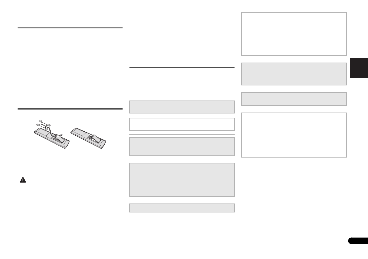
English
Français
Italiano
Español
Nederlands
Deutsch
Préparatifs
ATTENTION
Vérification des accessoires livrés avec
l’appareil
Veuillez vérifier que les accessoires suivants sont livrés avec
l’appareil :
•Microphone de configuration
• Télécommande
• Piles à anode sèche AAA IEC R03 (pour vérifier le bon
fonctionnement du système) x 2
• Antenne cadre AM
• Antenne filaire FM
• Cordon d’alimentation
• Carte de garantie
• Mode d’emploi (CD-ROM)
•Le présent Guide de démarrage
Mise en place des piles
Les piles de la télécommande fournies avec l’appareil
permettent d’effectuer les premières opérations ; il est
possible qu’elles ne durent pas très longtemps. Nous
recommandons l’usage de piles alcalines, dont la durée de
vie est supérieure.
• Une mauvaise utilisation des piles peut provoquer des
accidents tels que fuites ou explosions. Veuillez observer
les recommandations suivantes :
-
N’utilisez jamais des piles neuves et usagées dans le
même appareil.
-
Insérez les piles en respectant les indications de
polarité situées à l’intérieur du boîtier.
-
Des piles de même forme peuvent avoir des voltages
différents. N’utilisez jamais des piles de voltage différent
dans le même appareil.
-
Au moment d’éliminer les piles usagées, veuillez
respecter les réglementations gouvernementales ou les
recommandations publiques relatives à la protection de
l’environnement en vigueur dans votre pays ou région.
-
N’utilisez ni ne conservez les piles sous la lumière
directe du soleil ou dans un endroit excessivement
chaud, comme une voiture ou à proximité d’un appareil
de chauffage. Les piles risqueraient de fuir, de
surchauffer, d’exploser ou de s’enflammer. Ceci
pourrait aussi réduire la durée de vie et les
performances des piles.
Organigramme des réglages sur le récepteur
Cet appareil est un récepteur AV à part entière présentant un
grand nombre de fonctions et de prises. Il peut être utilisé
facilement lorsque les raccordements et les réglages
mentionnés ci-dessous ont été effectués.
Les couleurs des étapes ont la signification suivante :
Élément nécessitant un réglage (Ces éléments sont traités
dans le présent Guide de démarrage).
Réglage à effectuer si nécessaire (Ces éléments sont
traités dans le Mode d’emploi inclus dans le CD-ROM).
1
Raccordement des enceintes
• Installation des enceintes (page 7)
• Raccordement des enceintes (page 8)
2
Raccordement des composants
•À propos du raccordement des sorties vidéo (page 10)
• Raccordement d’un téléviseur et de périphériques de
lecture (page 11)
• Raccordement des antennes (page 14)
• Branchement du récepteur (page 15)
3
Mise sous tension
4
Configuration de l’option Pre Out
(Lors du raccordement des enceintes avant-haut.)
Menu d’affectation d’entrée
(Si vous voulez effectuer d’autres liaisons que celles
recommandées.)
Utilisation de la fonction Audio Return Channel
(Lorsque le téléviseur connecté prend en charge la
fonction HDMI Audio Return Channel.)
5
Utilisez la configuration automatique à l’écran
MCACC pour configurer votre système
• Configuration automatique du son surround (MCACC)
(page 16)
6
Lecture d’une source (page 18)
• Les modes d’écoute de votre système (page 18)
7
Réglage des préférences de son
• Utilisation de la fonction Sound Retriever
• Un meilleur son grâce à la fonction Phase Control
• Écoute avec l’équilibrage acoustique EQ
• Utilisation du traitement de canal surround arrière
• Réglage de la fonction Up Mix
• Réglage des options audio
• Configuration manuelle des enceintes
5
Fr
Page 24
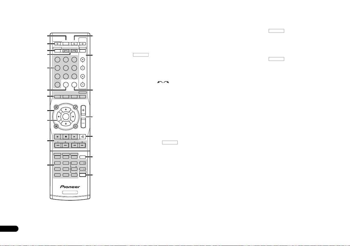
6
RECEIVER
RECEIVER
RECEIVER
Fr
Télécommande
Cette section explique l’utilisation de la télécommande de
l’appareil.
1
RECEIVER
2
RECEIVER DTV/TV
3
4
BD DVD
DVR/BDRCDCD-R
5
ADAPTER
VIDEO
6
AUTO/
DIRECT
7
AUDIO
PARAMETER
TOP
MENU
8
T
E
S
E
R
P
9
HOME
MENU
SETUP
PTY SEARCH
10
HDD
1
4
11
MIDNIGHT
7
DIMMER
CLR
+
BASS
10
INPUT SELECT
TUNER
STEREO
N
U
E
T
ENTER
T
E
U
N
DVD
2
SB CH
5
SPEAKERS
8
0
RECEIVER
SOURCESLEEP
TV
PORTABLE
SIGNAL SELS.RETRIEVER
ALC/
STANDARD
TUNER EDIT
TOOLS
RETURN
VCR
3
CH SELECT
6
LEV
9
LEV
ENTER
P
R
E
E
T
S
TRE
CONTROL
BD MENU
ADV SURR
MASTER
VOLUME
MENU
BAND
PHASE
SHIFT
INPUT
MUTE
CH
CH
12
TV
13
CH
VOL
14
15
16
DISP
17
EQ
18
1 SLEEP
Appuyez sur cette touche pour modifier le délai qui s’écoule
avant que le récepteur ne passe en mode veille (30 min –
60 min – 90 min – Off). Vous pouvez vérifier le temps restant
avant le passage en mode veille en appuyant une fois sur la
touche SLEEP.
2RECEIVER
Cette touche permet d’allumer le récepteur et de le mettre en
veille.
3
Pour attribuer la télécommande au contrôle du récepteur
(permet de sélectionner les commandes blanches au-dessus
des touches numérotées (MIDNIGHT, etc.)). Utilisez
également cette touche pour configurer le son surround ou
les paramètres audio.
4 INPUT SELECT
Servent à sélectionner la source d’entrée (page 18).
5 Touches de fonction d’entrée
Pour sélectionner la source d’entrée de ce récepteur
(page 18). Ceci permet de commander d’autres équipements
Pioneer avec la télécommande.
6 S.RETRIEVER
Appuyez sur cette touche pour restaurer un son de qualité
CD vers des sources audio compressées.
7 Touches de mode d’écoute
Utilisez ces touches pour sélectionner un mode d’écoute
(page 18).
8 Touches de réglage du récepteur
Appuyez d’abord sur pour accéder au menu :
AUDIO PARAMETER – Permet d’accéder aux options
Audio.
SETUP – Appuyez pour accéder au menu de
configuration du système.
RETURN – Permet de confirmer et de quitter l’écran du
menu affiché.
RECEIVER
Appuyez d’abord sur TUNER pour accéder au menu :
TUNER EDIT – Permet de mémoriser/nommer des
stations de radio à rappeler (page 19).
BAND – Permet de naviguer entre les bandes de signaux
radio AM, FM ST (stéréo) et FM MONO (page 19).
PTY SEARCH – Permet de rechercher des programmes
de type RDS.
9
///
Utilisez les touches fléchées pour régler votre système de son
surround.
(TUNE
/
, PRESET
/
), ENTER
Les touches TUNE / permettent de rechercher une
fréquence radio et les touches PRESET / servent à
rechercher une station de radio préréglée (page 19).
10 Touches de commande du récepteur
Appuyez d’abord sur pour accéder au menu :
BASS –/+, TRE –/+ – Pour ajuster les fréquences graves
et les fréquences aiguës.
• Ces commandes sont désactivées lorsque le mode
d’écoute est réglé sur DIRECT ou sur PURE DIRECT.
11 Touches de commande du récepteur
Appuyez d’abord sur pour accéder au menu :
SB CH – Appuyez sur cette touche pour sélectionner le
mode ON, AUTO, ou OFF pour le canal surround arrière.
CH SELECT – Appuyez sur cette touche plusieurs fois
pour sélectionner un canal, puis sur LEV +/– pour régler
le niveau sur.
LEV +/– – Ces touches permettent d’ajuster le niveau des
canaux.
EQ – Appuyez sur cette touche pour sélectionner/
désélectionner le réglage Acoustic Calibration EQ.
MIDNIGHT – Permet de sélectionner le mode d’écoute
Midnight ou Loudness.
SPEAKERS – Utilisez cette touche pour utiliser ou non le
système d’enceintes.
PHASE – Permet d’activer/de désactiver la correction de
phase.
DIMMER – Obscurcit ou éclaircit l’affichage.
12SOURCE
Cette touche permet de mettre sous/hors tension d’autres
composants connectés au récepteur.
13 Touches TV CONTROL
Ces touches de commande peuvent être utilisées
uniquement avec les téléviseurs Pioneer.
14 SIGNAL SEL
Appuyez pour sélectionner le signal audio d’entrée de
l’équipement à partir duquel vous souhaitez effectuer la
lecture.
15 MASTER VOLUME +/–
Permet de régler le volume d’écoute.
16 MUTE
Permet de couper/restaurer le son.
17 DISP
Permet de sélectionner l’écran de cet appareil.
18 SHIFT
Appuyez sur cette touche pour accéder aux commandes
‘encadrées’ (situées au-dessus des touches) de la
télécommande.
Page 25
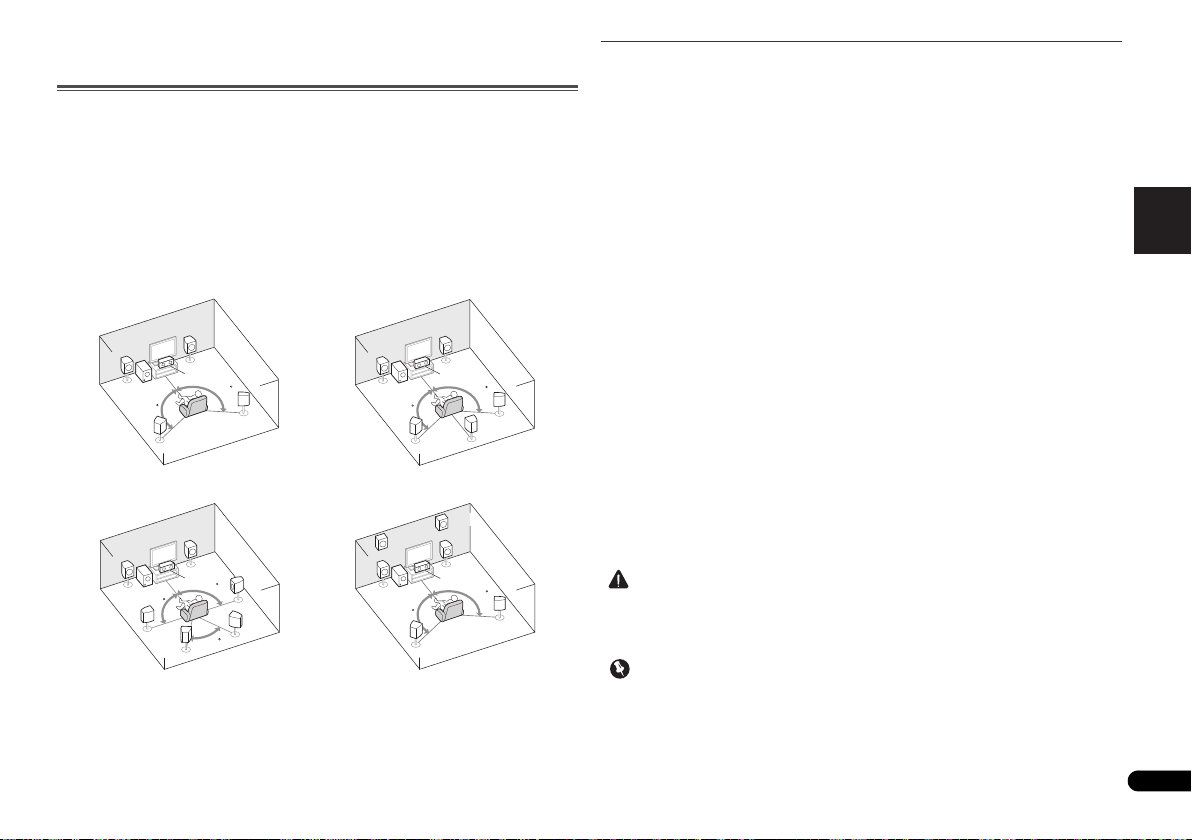
English
Français
Italiano
Español
Nederlands
Deutsch
Raccordement de votre équipement
ATTENTION
Important
Système surround à 5.1 canaux :
Système surround (surround
arrière) à 7.1 canaux :
a
Système surround (surround
avant-haut) à 7.1 canaux :
a
Système surround (surround
arrière) à 6.1 canaux :
a
Installation des enceintes
Un système surround de type 5.1 peut être obtenu en connectant les enceintes avant gauche
et droite (
L/R
subwoofer (
De plus, à l’aide d’un amplificateur externe, vous pouvez connecter les enceintes surround
gauche et droite (SBL/SBR) et les enceintes avant-haut gauche et droite (FHL/FHR) pour
réaliser un système surround de type 7.1 canaux.
•Vous pouvez aussi connecter une enceinte surround arrière (SB) afin d’obtenir un système
Pour obtenir le meilleur son surround possible, installez vos enceintes conformément à
l’illustration ci-dessous.
a. Cette disposition est possible uniquement lorsque l’amplificateur supplémentaire est raccordé à
), l’enceinte centrale (C), les enceintes surround gauche et droite (SL/SR) et le
SW
).
surround à 6.1 canaux.
L
L
l’appareil et que les enceintes surround arrière ou surround avant-haut sont raccordées à
l’amplificateur. Pour plus de détails, voir la section Connectez les enceintes surround arrière ou
surround avant-haut à la page 8.
R
L
C
SBL
120
SR
SL
R
C
SR
90
SBR
60
L
SW
120
SW
90
SL
SW
FHL
SW
R
C
120
SB
SL
FHR
C
120
SL
Conseils d’installation des enceintes
L’emplacement des enceintes dans la pièce d’écoute a une grande influence sur la qualité du
son obtenu. Les conseils suivants vous permettront d’obtenir le meilleur son avec votre
système.
• Le caisson de basses peut être placé sur le sol. L’idéal est de placer les autres enceintes
au niveau de vos oreilles en position d’écoute. Il est déconseillé de poser les enceintes sur
le sol (à l’exception du caisson de graves) ou de les installer très haut en position murale.
• Pour obtenir un effet stéréo optimal, écartez les enceintes avant de 2 à 3 mètres en les
plaçant à égale distance du téléviseur.
• Si vous prévoyez de placer les enceintes à côté d’un téléviseur à écran cathodique, utilisez
des enceintes protégées contre les interférences électromagnétiques, ou placez les
enceintes à une distance suffisante de l’écran.
• Si vous utilisez une enceinte centrale, placez les enceintes avant à un angle plus grand.
Sinon, placez-les à un angle plus étroit.
• Placez l’enceinte centrale au-dessus ou en dessous du téléviseur de sorte que le son du
canal central semble provenir de l’écran du téléviseur. Assurez-vous également que
l’enceinte centrale ne traverse pas la ligne formée par le bord d’attaque des enceintes
avant gauche et droite.
•Il vaut mieux placer les enceintes de manière à réaliser un angle ouvert vers la position
d’écoute. L’angle dépend de la taille de la pièce. Utilisez un angle inférieur pour les pièces
plus grandes.
120
SR
R
120
SR
• Les enceintes surround et surround arrière doivent être placées 60 cm à 90 cm plus haut
que vos oreilles et légèrement inclinées vers le bas. Assurez-vous que les enceintes ne
sont pas face à face. Pour les signaux DVD-Audio, les enceintes doivent être plus
rapprochées de l’auditeur que lors de la lecture sur un appareil de cinéma à domicile.
• Si les enceintes surround ne peuvent pas être placées dir
d’écoute dans un système à 7.1 canaux, l’effet surround pourra être amélioré en
désactivant la fonction Up Mix (voir la section Réglage de la fonction Up Mix du Mode
d’emploi sur le CD-ROM).
•Essayez de placer les enceintes surround à la même distance de la position d’écoute que
les enceintes avant et centrale. Sinon, l’effet de son surround sera affaibli.
• Placez les enceintes avant-haut gauche et droite à au moins un mètre à la verticale audessus des enceintes avant gauche et droite.
• Assurez-vous que toutes les enceintes sont correctement installées. Ceci permet non
seulement d’améliorer la qualité du son, mais aussi de réduire les risques de dommages
ou de blessures, en empêchant les enceintes d’être renversées ou de tomber en cas de
choc externe ou de secousse telle qu’un tremblement de terre.
•Vous devez disposer d’un amplificateur supplémentaire pour raccorder les enceintes
surround arrière ou surround avant-haut. Raccordez l’amplificateur supplémentaire aux
sorties PRE OUT SURR BACK/FRONT HEIGHT de cet appareil et raccordez les enceintes
surround arrière ou les enceintes surround avant-haut à l’amplificateur supplémentaire
(voir la section Connectez les enceintes surround arrière ou surround avant-haut à la
page 8).
ectement à côté de la position
7
Fr
Page 26
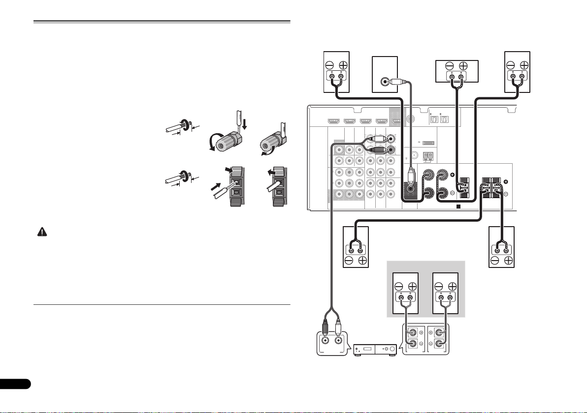
Raccordement des enceintes
ATTENTION
12 3
10 mm
12 3
10 mm
LINE LEVEL
INPUT
ANALOG
RL
AUDIO IN
SPEAKER R SPEAKER L
Centrale
Surround droite
Avant droite
Amplificateur du canal surround arrière
ou surround avant-haut
Avant gauche
Caisson de basses
Surround gauche
Droite
Gauche
Connectez les enceintes surround
arrière ou surround avant-haut
Le récepteur fonctionnera avec seulement deux enceintes stéréo (les enceintes avant sur le
schéma), mais il est recommandé d’en utiliser au moins trois ; une configuration complète de
huit enceintes est cependant idéale pour la production du son surround.
Vérifiez que l’enceinte droite est raccordée à la borne droite (R) et que l’enceinte gauche est
raccordée à la borne gauche (L). Assurez-vous également que les bornes positive et négative
(+/–) du récepteur sont reliées aux bornes positive et négative des enceintes.
Assurez-vous que tous les branchements ont été effectués correctement avant de raccorder cet
appareil au secteur.
Branchement des fils nus
Bornes des enceintes avant :
1
Torsadez ensemble les brins de fil
dénudés.
2
le fil.
3
Bornes de l’enceinte centrale et des enceintes
surround :
1
dénudés.
2
et insérez le fil dénudé.
3
• Les bornes des haut-parleurs sont sous une tension DANGEREUSE. Pour éviter tout
• Assurez-vous que tous les brins de fil dénudés du câble d’enceinte sont torsadés
Connectez les enceintes surround arrière ou surround avant-haut
Raccordez les sorties PRE OUT SURR BACK/FRONT HEIGHT de l’appareil et de
l’amplificateur supplémentaire afin d’ajouter des enceintes surround arrière ou surround
avant-haut.
•Les paramètres Pre Out doivent être configurés lorsque les raccordements ci-dessus sont
8
Fr
Libérez la borne de l’enceinte et insérez-y
Refermez la borne.
Torsadez ensemble les brins de fil
Poussez sur les languettes pour les ouvrir
Relâchez les languettes.
risque de décharge électrique lors du branchement et du débranchement des câbles de
haut-parleur, débranchez le cordon d’alimentation avant de toucher des parties non
isolées.
ensemble et insérés complètement dans la borne de l’enceinte. Si une partie du fil
d’enceinte exposé entre en contact avec le panneau arrière, l’alimentation peut être
coupée par mesure de sécurité.
réalisés. Sélectionnez SURR.BACK dans le cas où les enceintes surround arrière sont
connectées et HEIGHT lorsque les enceintes surround avant-haut sont raccordées (Si
aucune des enceintes surround arrière et surround avant-haut ne sont connectées,
n’importe quelle option convient) (voir la section Configuration de l’option Pre Out du Mode
d’emploi sur le CD-ROM).
•Vous pouvez également raccorder l’amplificateur supplémentaire aux sorties Pre Out de
canal surround arrière pour ajouter une seule enceinte. Dans ce cas, connectez
l’amplificateur à la borne gauche (L (Single)) uniquement.
COAXIAL
TV/SAT
CD-R/TAPE
BD
OUT
SURR BACK/
FRONT HEIGHT
(
Single
PRE OUT
CD
IN
DVD
L
R
L
R
L
R
)
(
OUTPUT 5 V
0.1 A MAX
FM
UNBAL
75
SUBWOOFER
PRE OUT
1
IN
ASSIGNABLE
(CD)
ADAPTER PORT
)
ANTENNA
AM LOOP
OPTICAL
IN
IN
1
2
(
)
(
TV/SAT
CD-R/TAPE
FRONT
RL
SPEAKERS
ASSIGNABLE
)
A
CENTER
SURROUND
RL
HDMI
DVR/BDR IN
VIDEO
MONITOR
OUT
DVR/
BDR
OUTINDVD IN
1
IN
(
)
DVD
ASSIGNABLE
2
IN
(
DVR/
)
BDR
MONITOR
OUT
YP
COMPONENT VIDEO
DVD IN
TV/SATINBD
B PR
BD IN VIDEO IN
AUDIO
DVR/BDR
IN
OUT
IN IN
IN
Page 27
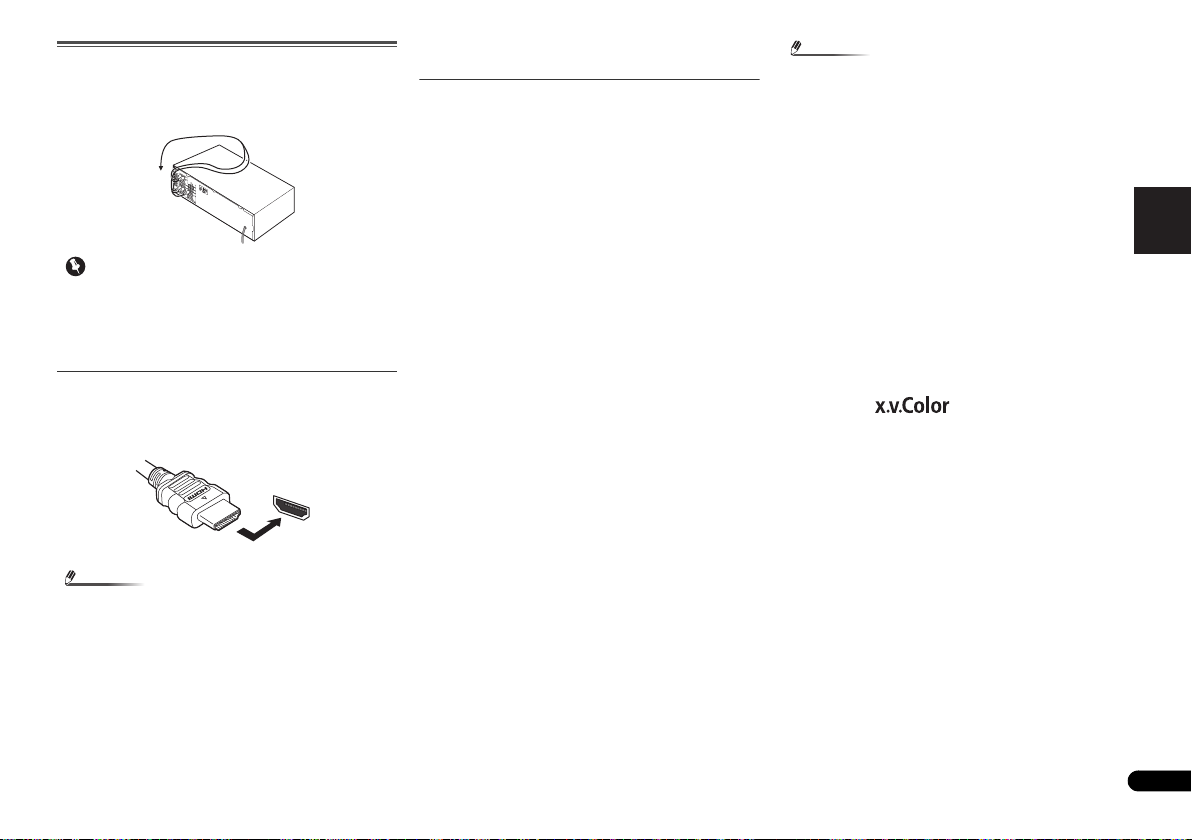
English
Français
Italiano
Español
Nederlands
Deutsch
Raccordements des câbles
Important
Remarque
Remarque
HDMI
Veillez à ne pas plier les câbles par dessus l’appareil
(conformément à l’illustration). Dans ce cas, le champ
magnétique produit par les transformateurs de l’appareil
pourrait provoquer le ronflement des enceintes.
• Avant un raccordement ou une modification de
raccordement, mettez l’appareil hors tension et
débranchez le cordon d’alimentation de la prise secteur.
• Avant de débrancher le cordon d’alimentation, mettez
l’appareil en veille.
Câbles HDMI
Les signaux vidéo et audio peuvent être transmis
simultanément via un seul câble. Dans le cas où le lecteur et
le téléviseur sont connectés via cet appareil, utilisez des
câbles HDMI pour les deux connexions.
Veillez à raccorder la borne dans le sens qui convient.
• Réglez le paramètre HDMI sur THRU (THROUGH) et
réglez le signal d’entrée sur HDMI, si vous souhaitez
entendre la sortie audio HDMI de votre téléviseur (aucun
son ne sera transmis par ce récepteur) (voir la section
Réglage des options audio et Sélection du signal d’entrée
audio du Mode d’emploi sur le CD-ROM).
• Si le signal vidéo n’apparaît sur votre téléviseur, essayez
d’ajuster les réglages de la résolution de votre composant
ou écran. Notez que certains composants (par exemple
les consoles de jeux vidéo) ont des résolutions qui ne
peuvent pas être affichées. Dans ce cas, utilisez une
connexion composite (analogique).
• Lorsque le signal vidéo HDMI est 480i, 480p, 576i ou 576p,
il est impossible de recevoir le son Multi Ch PCM et HD.
À propos de HDMI
La liaison HDMI transfère des signaux vidéo numériques non
compressés de même que la plupart des signaux audio
compatibles avec le composant raccordé, par exemple les
signaux des DVD-Vidéo, DVD-Audio, SACD, Dolby Digital
Plus, Dolby TrueHD, DTS-HD Master Audio (voir ci-dessous
pour les restrictions), CD-Vidéo/Super VCD et CD.
Ce récepteur intègre une Interface Multimédia Haute
Définition (HDMI
Il prend en charge les fonctions suivantes lorsque les liaisons
HDMI sont utilisées.
• Transfert numérique de vidéo non compressée (contenu
protégé par le HDCP (1080p/24, 1080p/60, etc.))
• Transmission de signal 3D
• Transfert des signaux Deep Color
• Transfert de signaux x.v.Color
• Audio Return Channel
• Entrée de signaux audio numériques PCM linéaires
multicanaux (192 kHz ou inférieur) jusqu’à 8 canaux
• Entrée des signaux audio numériques aux formats
suivants :
– Dolby Digital, Dolby Digital Plus, DTS, Son à débit élevé
(Dolby TrueHD, DTS-HD Master Audio), DVD-Audio, CD,
SACD (DSD 2 canaux uniquement), Video CD, Super VCD
• Fonctionnement synchronisé avec les équipements dotés
de la fonction Control HDMI (voir la section Fonction
Control HDMI du Mode d’emploi sur le CD-ROM).
®
).
• Utilisez un câble High Speed HDMI®. L’utilisation d’un
câble HDMI de type autre que High Speed HDMI
causer des dysfonctionnements.
• L’utilisation d’un câble HDMI équipé d’un égaliseur
intégré peut provoquer des dysfonctionnements.
•Les options 3D, Deep Color, x.v.Color signal transfer et
Audio Return Channel sont uniquement disponibles
lorsqu’un composant compatible est connecté.
• La transmission du signal audio numérique HDMI
nécessite plus de temps pour être reconnue. Pour cette
raison, une interruption du signal audio peut se produire
lorsque vous changez de mode audio ou lorsque vous
commencez la lecture.
• Le fait de mettre en marche ou d’arrêter le périphérique
connecté à la borne HDMI OUT de cet appareil, ou de
déconnecter/connecter le câble HDMI pendant la lecture
peut produire des bruits parasites ou même interrompre
le signal audio.
HDMI, le logo HDMI et High-Definition Multimedia Interface
sont des marques commerciales ou des marques déposées de
HDMI Licensing, LLC aux États-Unis et dans d’autres pays.
“x.v.Color” et sont des marques
commerciales de Sony Corporation.
®
peut
9
Fr
Page 28
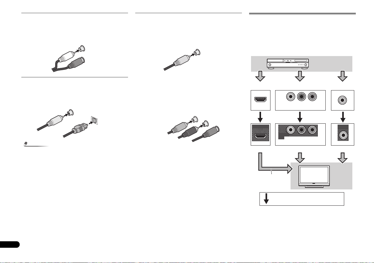
Câbles audio analogiques
Remarque
L
R
AUDIO
Blanc (Gauche)
Rouge (Droit)
Câble audio
numérique coaxial
Câble optique
VIDEO
Jaune
Y
P
B
P
R
COMPONENT VIDEO
Vert (Y)
Rouge (PR)
Bleu (PB)
Borne pour le raccordement d’une source
Borne pour le raccordement d’un téléviseur
Périphérique de
lecture
Téléviseur
L’affichage OSD
n’apparaît pas.
Signaux vidéo pouvant être transmis.
Utilisez des câbles phono stéréo RCA pour raccorder les
appareils audio analogiques. Ces câbles sont le plus souvent
rouges et blancs ; les fiches rouges doivent être raccordées
aux bornes R (côté droit) et les fiches blanches aux bornes L
(côté gauche).
Câbles vidéo
Câbles vidéo RCA standard
Ces câbles sont couramment utilisés pour les
raccordements vidéo et ils sont utilisés pour le raccordement
à des bornes vidéo en composantes. Les fiches jaunes les
distinguent des câbles audio.
À propos du raccordement des sorties vidéo
Ce récepteur ne comporte pas de convertisseur vidéo. Les
câbles vidéo en composantes ou les câbles HDMI que vous
utilisez pour le raccordement à l’appareil d’entrée doivent
également servir pour le raccordement au téléviseur.
Les signaux des entrées vidéo analogiques (composite et
composant) de cet appareil ne seront pas transmis par la
sortie HDMI OUT.
Câbles audio numériques
Les câbles audio numériques coaxiaux ou les câbles
optiques disponibles dans le commerce doivent être utilisés
pour raccorder les appareils numériques au récepteur.
• Lors du raccordement de câbles optiques, faites attention
à ne pas endommager le cache qui protège la prise
optique lors de l’insertion de la fiche.
• Pour ranger le câble optique, l’enrouler sans le serrer.
Vous pourriez endommager le câble en l’enroulant de
façon trop serrée.
•Vous pouvez également utiliser un câble vidéo RCA
standard pour les raccordements numériques coaxiaux.
10
Fr
COAXIAL
IN
OPTICAL
IN
Câbles vidéo en composantes
Les câbles vidéo en composantes permettent d’obtenir la
meilleure reproduction couleur possible de votre source
vidéo. Le signal couleur de votre téléviseur regroupe le signal
de luminance (Y) et la couleur (les signaux P
sortie. Les interférences entre les signaux sont ainsi évitées.
B et PR) et la
IN
HDMI
OUT
HDMI
IN
YPBP
COMPONENT VIDEO
MONITOR
OUT
YPBP
COMPONENT VIDEO
IN
R
R
VIDEO
MONITOR
OUT
VIDEO
Page 29
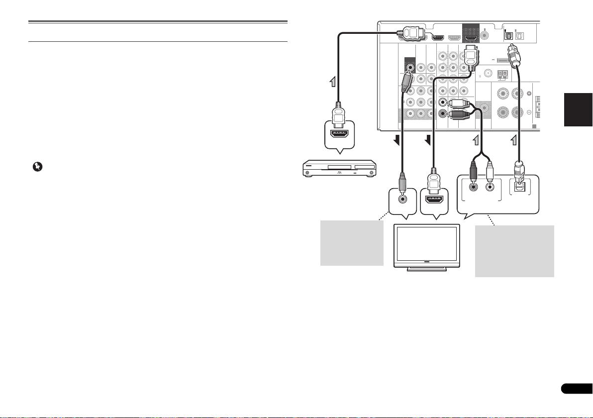
English
Français
Italiano
Español
Nederlands
Deutsch
Raccordement d’un téléviseur et de périphériques de lecture
Important
VIDEO
MONITOR
OUT
N
VIDEO IN
HDMI IN
HDMI OUT
RL
DIGITAL AUDIO OUTANALOG AUDIO OUT
OPTICAL
Sélectionnez-en une
Téléviseur compatible HDMI/DVI
Lecteur de Blu-ray Disc
compatible HDMI/DVI
Cette connexion est
nécessaire afin de
faire apparaître
l’affichage OSD de
l’appareil sur le
téléviseur.
Si le téléviseur ne prend pas
en charge la fonction HDMI
Audio Return Channel, cette
connexion est nécessaire
pour écouter le son du
téléviseur par
l’intermédiaire du récepteur.
Connexion au moyen de l’interface HDMI
Si vous avez un composant équipé d’une prise HDMI ou DVI (avec HDCP) (Lecteur Blu-ray
Disc, etc.), vous pouvez le raccorder à ce récepteur à l’aide d’un câble HDMI disponible dans
le commerce.
Si le téléviseur et les équipements de lecture connectés prennent en charge la fonction
d’Control HDMI, cette fonction pratique peut être utilisée (voir la section Fonction Control
HDMI du Mode d’emploi sur le CD-ROM).
• La connexion et/ou le réglage suivant est nécessaire pour écouter le son du téléviseur par
l’intermédiaire du récepteur.
-
Si le téléviseur ne prend pas en charge la fonction HDMI Audio Return Channel,
connectez le récepteur et le téléviseur à l’aide de câbles audio (comme indiqué).
-
Si le téléviseur prend en charge la fonction HDMI Audio Return Channel, le son du
téléviseur est envoyé vers le récepteur via la prise HDMI et il n’est alors pas nécessaire
de connecter un câble audio. Dans ce cas, réglez l’option ARC sur ON dans le menu de
HDMI Setup (voir la section Menu HDMI Setup du Mode d’emploi sur le CD-ROM).
• Si cet appareil est connecté à un téléviseur via un câble HDMI, l’affichage des
informations à l’écran (OSD) n’apparaît pas. Veillez à utiliser un câble vidéo analogique
RCA pour réaliser le branchement. Dans ce cas, si vous souhaitez que l’affichage OSD
apparaisse (pour effectuer la configuration, etc.), basculez l’entrée TV sur le mode
analogique.
• Lorsque la fonction Control HDMI est activée (ON) et que le récepteur est connecté via un
câble HDMI à un téléviseur compatible, lorsque vous commutez l’entrée du téléviseur sur
vidéo composite ou en composantes, il se peut que l’entrée du récepteur commute
automatiquement sur TV/SAT. Si cela se produit, commutez l’entrée du récepteur sur le
réglage d’origine, ou désactivez la fonction Control HDMI (voir la section Menu HDMI
Setup du Mode d’emploi sur le CD-ROM).
HDMI
DVR/BDR IN
VIDEO
MONITOR
OUT
DVR/
BDR
OUTINDVD IN
1
IN
(
)
DVD
ASSIGNABLE
2
IN
(
DVR/
)
BDR
MONITOR
OUT
YP
COMPONENT VIDEO
DVD IN
TV/SATINBD
BPR
BD IN VIDEO IN
AUDIO
DVR/BDR
IN
OUT
IN IN
IN
TV/SAT
CD-R/TAPE
BD
OUT
SURR BACK/
FRONT HEIGHT
L
(
Single
PRE OUT
R
CD
L
R
L
IN
R
DVD
COAXIAL
)
(
OUTPUT 5 V
0.1 A MAX
FM
UNBAL
75
SUBWOOFER
PRE OUT
1
IN
(CD)
ADAPTER PORT
)
AM LOOP
ASSIGNABLE
ANTENNA
OPTICAL
IN
IN
1
2
(
)
(
TV/SAT
CD-R/TAPE
FRONT
RL
SPEAKERS
ASSIGNABLE
)
CE
A
11
Fr
Page 30
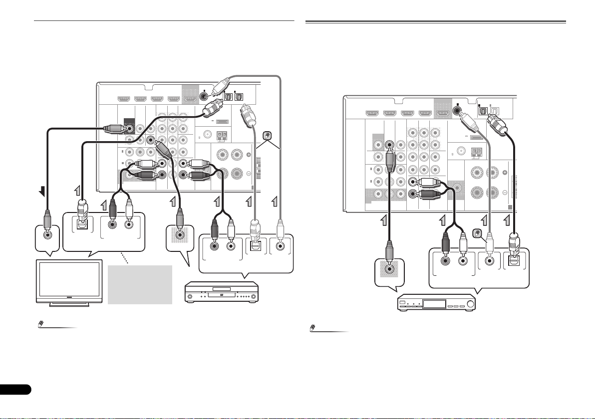
Raccordement d’un équipement dépourvu de borne HDMI
Remarque
Remarque
T
RL
DIGITAL AUDIO OUT ANALOG AUDIO OUT
OPTICAL
RL
DIGITAL AUDIO OUTANALOG AUDIO OUT
OPTICAL COAXIAL
VIDEO IN
VIDEO OUT
Sélectionnez-en une
Téléviseur
Lecteur de DVD
Sélectionnez-en une
Cette liaison est
nécessaire pour
pouvoir écouter le son
du téléviseur ou du
récepteur.
T
RL
DIGITAL AUDIO OUTANALOG AUDIO OUT
OPTICALCOAXIAL
VIDEO OUT
Sélectionnez-en une
Boîtier décodeur, etc.
Ce schéma montre les connexions d’un téléviseur et d’un lecteur DVD (ou autre équipement
de lecture) dépourvus de borne HDMI à cet appareil.
• Si le téléviseur et le lecteur sont tous deux équipés de prises vidéo en composantes, vous
pouvez aussi les raccorder. Pour plus d’information à ce sujet, voir la section Utilisation
des prises femelles vidéo en composantes à la page 13.
COAXIAL
CD-R/TAPE
BD
OUT
SURR BACK/
FRONT HEIGHT
L
(
Single
PRE OUT
R
CD
L
R
L
IN
R
DVD
IN
(CD)
)
(
OUTPUT 5 V
0.1 A MAX
FM
UNBAL
75
SUBWOOFER
PRE OUT
1
ASSIGNABLE
ADAPTER PORT
)
ANTENNA
AM LOOP
IN
IN
1
2
(
)
(
TV/SAT
CD-R/TAPE
FRONT
RL
SPEAKERS
OPTICAL
ASSIGNABLE
)
CEN
A
HDMI
DVR/BDR IN
VIDEO
MONITOR
OUT
DVR/
BDR
OUTINDVD IN
1
IN
(
)
DVD
ASSIGNABLE
2
IN
(
DVR/
)
BDR
MONITOR
OUT
YP
COMPONENT VIDEO
DVD IN
TV/SATINBD
BPR
BD IN VIDEO IN
AUDIO
DVR/BDR
IN
OUT
IN IN
IN
TV/SAT
Raccordement d’un récepteur satellite ou d’un boîtier décodeur
numérique
Les récepteurs satellites et par câble, ainsi que les syntoniseurs de téléviseur numérique
terrestre sont tous des exemples de ce que l’on appelle boîtiers décodeurs.
• Si le boîtier décodeur ou l’équipement vidéo possède aussi une sortie HDMI ou une sortie
vidéo en composantes, vous pouvez également la raccorder. Pour plus d’informations, voir
les sections Connexion au moyen de l’interface HDMI à la page 11 et Utilisation des prises
femelles vidéo en composantes à la page 13.
COAXIAL
CD-R/TAPE
BD
OUT
SURR BACK/
FRONT HEIGHT
L
(
Single
PRE OUT
R
CD
L
R
L
IN
R
DVD
)
(
OUTPUT 5 V
0.1 A MAX
FM
UNBAL
75
SUBWOOFER
PRE OUT
1
IN
(CD)
ADAPTER PORT
)
AM LOOP
ASSIGNABLE
ANTENNA
OPTICAL
IN
IN
1
2
ASSIGNABLE
(
)
(
TV/SAT
CD-R/TAPE
FRONT
RL
SPEAKERS
)
CEN
A
HDMI
DVR/BDR IN
VIDEO
MONITOR
OUT
DVR/
BDR
OUTINDVD IN
1
IN
(
)
DVD
ASSIGNABLE
2
IN
(
DVR/
)
BDR
MONITOR
OUT
YP
COMPONENT VIDEO
DVD IN
TV/SATINBD
BPR
BD IN VIDEO IN
AUDIO
DVR/BDR
IN
OUT
IN IN
IN
TV/SAT
• Pour écouter le son d’un lecteur DVD connecté à ce récepteur via un câble optique ou un
12
Fr
câble coaxial, commutez d’abord l’entrée sur DVD, puis utilisez la touche SIGNAL SEL
pour sélectionner le signal audio O2 (OPTICAL2) ou C1 (COAXIAL1).
• Pour écouter le son d’un composant source connecté à ce récepteur via un câble coaxial,
commutez d’abord l’entrée sur TV/SAT, puis utilisez la touche SIGNAL SEL pour
sélectionner le signal audio C1 (COAXIAL1).
Page 31

English
Français
Italiano
Español
Nederlands
Deutsch
Raccordement d’un enregistreur HDD/DVD, d’un enregistreur Blu-ray
Remarque
Important
T
Sélectionnez-en une
Enregistreur HDD/DVD,
enregistreur Blu-ray Disc, etc.
C
FRONT HEIGHT
Y
P
B
PR
COMPONENT VIDEO IN
Y
P
B
PR
COMPONENT VIDEO OUT
Lecteur de DVD
Téléviseur
Disc et d’autres sources vidéo
Ce récepteur est muni d’entrées et de sorties audio/vidéo adaptées pour la connexion
d’enregistreurs analogiques ou numériques, tels que des enregistreurs HDD/DVD ou des
enregistreurs Blu-ray Disc.
• Seuls les signaux qui sont envoyés sur la borne VIDEO IN peuvent être so rtis au niveau de
la borne VIDEO OUT.
• Les signaux qui sont envoyés sur la borne numérique ne peuvent pas être sortis au niveau
de la borne analogique.
COAXIAL
CD-R/TAPE
BD
VIDEO OUT
OUT
SURR BACK/
FRONT HEIGHT
L
(
Single
PRE OUT
R
CD
L
R
L
IN
R
DVD
IN
(CD)
)
(
OUTPUT 5 V
0.1 A MAX
FM
UNBAL
75
SUBWOOFER
PRE OUT
1
ASSIGNABLE
ADAPTER PORT
)
ANTENNA
AM LOOP
RL
OPTICAL
IN
IN
1
2
ASSIGNABLE
(
)
(
TV/SAT
CD-R/TAPE
FRONT
RL
SPEAKERS
DIGITAL AUDIO OUTANALOG AUDIO OUT
)
A
OPTICAL
HDMI
RL
ANALOG AUDIO IN
DVR/BDR IN
VIDEO
MONITOR
OUT
DVR/
BDR
OUTINDVD IN
1
IN
(
)
DVD
ASSIGNABLE
2
IN
(
DVR/
)
BDR
MONITOR
OUT
YP
COMPONENT VIDEO
VIDEO IN
DVD IN
TV/SATINBD
BPR
BD IN VIDEO IN
AUDIO
DVR/BDR
IN
OUT
IN IN
IN
TV/SAT
Utilisation des prises femelles vidéo en composantes
Les prises femelles vidéo en composantes offrent généralement une qualité d’image
supérieure aux prises vidéo composites. De plus, la fonction de balayage progressif permet
d’obtenir des images extrêmement stables et sans scintillement (si la source et le téléviseur
sont compatibles). Consultez les modes d’emploi de votre téléviseur et de votre appareil
source pour vous assurer qu’ils sont compatibles avec la fonction de balayage progressif.
• Pour ce qui concerne le raccordement audio, consultez la section Raccordement d’un
équipement dépourvu de borne HDMI à la page 12.
• Si vous avez raccordé un composant source au récepteur au moyen d’une entrée vidéo en
composantes, votre téléviseur doit également être raccordé à la prise COMPONENT
VIDEO MONITOR OUT de ce récepteur.
• Si nécessaire, affectez les entrées vidéo en composantes aux entrées de la source que
vous venez de raccorder. Cette étape doit être exécutée uniquement si vos raccordements
ne respectent pas les raccordements par défaut suivants :
-
COMPONENT VIDEO IN 1: DVD
-
COMPONENT VIDEO IN 2: DVR/BDR
CEN
Pour plus d’informations à ce sujet, voir la section Menu d’affectation d’entrée du Mode
d’emploi sur le CD-ROM.
MONITOR
OUT
DVR/
BDR
OUTINDVD IN
1
IN
(
)
DVD
ASSIGNABLE
2
IN
(
DVR/
)
BDR
MONITOR
OUT
COMPONENT VIDEO
TV/SATINBD
B PR
YP
DVR/BDR
IN
OUT
IN IN
IN
TV/SAT
D-R/TAPE
ADAPTER PORT
L
(
)
Single
(
OUTPUT 5 V
)
PRE OUT
0.1 A MAX
R
ANTENNA
FM
UNBAL
CD
75
L
AM LOOP
FRONT
R
L
IN
R
DVD
BD
RL
SUBWOOFER
PRE OUT
SPEAKERS
C
A
• Pour écouter le son d’un composant sou rce connecté à ce récepteur via un câble optique,
commutez d’abord l’entrée sur DVR/BDR, puis utilisez la touche SIGNAL SEL pour
sélectionner le signal audio O2 (OPTICAL2).
13
Fr
Page 32

Raccordement d’autres appareils audio
Remarque
N
Sélectionnez-en une
CD-R, MD, DAT,
magnétophone, etc.
ANTENNA
FM
UNBAL
75
AM LOOP
2
1
3
4
fig. a
fig. b
ANTENNA
FM
UNBAL
75
Connecteur PAL simple
Câble coaxial 75
ANTENNA
AM LOOP
Antenne extérieure
5 m à 6 m
Antenne intérieure
(câble avec protection
vinyle)
Le nombre et le type de raccordement dépendent des
appareils que vous désirez raccorder. Suivez les étapes cidessous pour raccorder un lecteur CD-R, MD, DAT, un
magnétophone ou tout autre appareil audio.
• Pensez à raccorder les appareils numériques aux prises
femelles audio analogiques si vous désirez enregistrer à
partir d’appareils numériques (lecteur MD par ex.) vers
des appareils analogiques et réciproquement.
HDMI
• Pour écouter le son d’un lecteur CD connecté à ce
récepteur via un câble optique ou un câble coaxial,
commutez d’abord l’entrée sur CD-R, puis utilisez la
touche SIGNAL SEL pour sélectionner le signal audio C1
(COAXIAL1).
14
Fr
DVD IN
DVR/BDR IN
VIDEO
MONITOR
TV/SATINBD
OUT
IN
DVR/
BDR
OUTINDVD IN
1
IN
(
)
DVD
ASSIGNABLE
2
IN
(
DVR/
)
BDR
MONITOR
OUT
YP
B PR
COMPONENT VIDEO
RL
REC
ANALOG AUDIO IN
CD-R/TAPE
SURR BACK/
FRONT HEIGHT
DVD
BD
RL
OUT
PRE OUT
CD
L
(
Single
R
L
R
L
IN
R
BD IN VIDEO IN
AUDIO
DVR/BDR
OUT
IN IN
IN
TV/SAT
COAXIAL
IN
(CD)
)
(
OUTPUT 5 V
0.1 A MAX
FM
UNBAL
75
SUBWOOFER
PRE OUT
1
ASSIGNABLE
ADAPTER PORT
)
ANTENNA
AM LOOP
DIGITAL AUDIO OUTANALOG AUDIO OUT
IN
IN
1
2
(
)
(
TV/SAT
CD-R/TAPE
FRONT
RL
SPEAKERS
OPTICALCOAXIAL
OPTICAL
ASSIGNABLE
)
Raccordement des antennes
Raccordez l’antenne cadre AM et l’antenne filaire FM comme
indiqué ci-dessous. Pour améliorer la réception et la qualité
du son, raccordez les antennes externes (voir la section
Utilisation des antennes externes ci-dessous).
CE
A
1
Poussez sur les languettes pour les ouvrir, puis insérez
complètement un fil dans chaque borne avant de relâcher
les languettes pour mettre en place les fils de l’antenne AM.
2
Reliez l’antenne cadre AM au pied joint.
Pour relier le pied à l’antenne, courbez-le dans le sens
indiqué par la flèche (fig. a), puis attachez le cadre sur le pied
(fig. b).
3
Placez l’antenne AM sur une surface plane en l’orientant
vers une direction qui offre la meilleure réception.
4
Raccordez l’antenne filaire FM à la prise d’antenne FM.
Pour de meilleurs résultats, déroulez l’antenne FM et fixez-la
sur un mur ou sur un encadrement de porte. Tendez-la, elle
ne doit pas être enroulée.
Utilisation des antennes externes
Pour améliorer la réception FM
Utilisez un connecteur de type PAL (non fourni) pour
raccorder une antenne FM externe.
Pour améliorer la réception AM
Connectez un fil recouvert de vinyle de 5 à 6 m ètres de l ong à
la borne d’antenne AM sans déconnecter l’antenne cadre
AM fournie.
Pour obtenir la meilleure réception possible, fixez ce fil
métallique horizontalement, à l’extérieur.
Page 33

English
Français
Italiano
Español
Nederlands
Deutsch
Branchement du récepteur
ATTENTION
Remarque
Ne raccordez le récepteur au secteur qu’après y avoir
connecté tous les composants, y compris les haut-parleurs.
• Tenez le cordon d’alimentation par sa prise lorsque vous
le manipulez. Ne débranchez pas l’appareil en tirant sur
le cordon et ne touchez jamais le cordon d’alimentation
avec les mains mouillées ; vous pourriez provoquer un
court-circuit ou prendre un choc électrique. Ne placez
pas l’appareil, un meuble ou tout autre objet sur le cordon
d’alimentation, et évitez de le pincer de toute autre
manière. Ne faites jamais de nœud dans le cordon et ne
le liez jamais avec d’autres câbles. Les cordons
d’alimentation doivent être acheminés de façon à ce
qu’on ne puisse pas marcher dessus. Un cordon
d’alimentation endommagé peut provoquer un incendie
ou un choc électrique. Vérifiez l’état du cordon de temps
à autre. Si le cordon est endommagé, demandez-en le
remplacement auprès du service après-vente agréé
Pioneer le plus proche.
• N’utilisez aucun autre cordon d’alimentation que celui
fourni avec cet appareil.
• N’utilisez pas le cordon d’alimentation fourni à d’autres
fins que celles décrites ci-après.
•Lorsque le récepteur n’est pas utilisé durant une longue
période (par ex. pendant les vacances), il est
recommandé de le débrancher, en retirant le connecteur
d’alimentation de la prise murale.
• Lorsque ce récepteur est relié à une prise secteur, un
processus d’initialisation HDMI de 2 à 10 secondes
commence. Durant celui-ci il n’est pas possible
d’effectuer d’autres opérations. Le témoin HDMI clignote
sur l’afficheur du panneau avant pendant l’initialisation,
et vous pouvez mettre le récepteur sous tension lorsque
le clignotement a cessé. Lorsque la fonction Control
HDMI est réglée sur OFF, vous pouvez sauter cette
procédure. Pour plus d’informations sur la fonction
Control HDMI, voir la section Fonction Control HDMI du
Mode d’emploi sur le CD-ROM.
1
Enfichez le cordon d’alimentation fourni dans la prise
AC IN à l’arrière du récepteur.
2
Enfichez l’autre extrémité dans une prise électrique.
15
Fr
Page 34

ATTENTION
Important
INPUT SELECT
SOURCESLEEP
TV
CONTROL
INPUT
RECEIVER
RECEIVER
BD DVD TV
DTV/TV
ENTER
MUTE
RETURN
PARAMETER
TOOLS
VOLUME
BAND
MENU
TOP
MENU
T
U
N
E
T
U
N
E
P
R
E
S
E
T
P
R
E
S
E
T
HOME
MENU
SETUP
PTY SEARCH
MASTER
VOLUME
SOUND
RETRIEVER
PORTABLE /
MCACC
SETUP MIC
PRESET ENTER
Trépied
Microphone
RECEIVER
1.Auto MCACC
Now Analyzing
Environment Check
Ambient Noise
Speaker YES/NO
Return
16
Fr
Configuration de base
Désactivation du mode d’affichage de
démonstration
Diverses informations (de démonstration) s’affichent sur le
panneau avant lorsque le récepteur ne fonctionne pas.
Il est possible de désactiver ce mode d’affichage. Pour plus
d’informations, voir la section Le menu FL Demo Mode du
Mode d’emploi sur le CD-ROM.
• Le mode démo est annulé automatiquement lorsque la
configuration Auto MCACC est effectué (voir ci-dessous).
Configuration automatique du son surround
(MCACC)
Le système de calibrage acoustique multicanaux (MultiChannel Acoustic Calibration, MCACC) mesure les
caractéristiques acoustiques de votre position d’écoute en
tenant compte du bruit ambiant, de la taille et de la distance
des enceintes et des tests sur le retard et le niveau de canal.
Une fois que vous avez installé le microphone fourni avec
votre système, le récepteur utilise les informations provenant
d’une série de tonalités de test afin d’optimiser les réglages
d’enceinte et l’égalisation pour une pièce spécifique.
• Les tonalités de test utilisées dans la configuration
MCACC automatique sont générées à un volume élevé.
• L’affichage à l’écran n’apparaît pas si vous avez effectué
la connexion au téléviseur via la sortie HDMI. Utilisez la
connexion composite ou en composantes pour
configurer le système.
• La configuration MCACC automatique remplace tous les
réglages précédemment effectués pour les enceintes.
• Si vous avez raccordé les enceintes surround arrière ou
les enceintes surround avant-haut, vérifiez que le
paramètre Pre Out est correctement réglé avant
d’exécuter la configuration automatique MCACC (voir la
section Configuration de l’option Pre Out du Mode
d’emploi sur le CD-ROM). (Voici un exemple expliquant
l’utilisation de l’affichage OSD lorsque des enceintes
surround arrière sont connectées.)
1
Allumez le récepteur et votre téléviseur.
2
Commutez l’entrée du téléviseur sur l’entrée qui
connecte ce récepteur au téléviseur via le câble
correspondant vidéo composite ou en composantes.
3
Connectez le microphone à la prise MCACC SETUP MIC
sur le panneau avant.
Assurez-vous qu’il n’y a pas d’obstacles entre les enceintes et
le microphone.
Si vous avez un trépied, utilisez-le pour y placer le
microphone afin qu’il soit au niveau des oreilles à votre
position d’écoute normale. Sinon, placez le microphone au
niveau des oreilles en utilisant une table ou une chaise.
4
Appuyez sur la touche de la télécommande,
puis sur la touche SETUP.
Le menu de configuration du système s’affiche sur le
téléviseur. Utilisez les touches /// et ENTER de la
télécommande pour naviguer dans les écrans et sélectionner
des options de menu. Appuyez sur la touche RETURN pour
sortir du menu actuel.
•Appuyez sur la touche SETUP à tout moment pour sortir
du menu System Setup. Si vous annulez la configuration
MCACC automatique à n’importe quel moment, le
récepteur abandonne la configuration automatiquement
et aucun réglage n’est enregistré.
• L’économiseur d’écran démarre automatiquement au
bout de trois minutes d’inactivité.
5
Sélectionnez ‘Auto MCACC’ dans le System Setup, puis
appuyez sur ENTER.
System Setup
1.Auto MCACC
2.Manual SP Setup
3.Input Assign
4.Pre Out Setting
5.HDMI Setup
6.Auto Power Down
7.FL Demo Mode
Return
• MIC IN clignote lorsque le microphone n’est pas
raccordé à la prise MCACC SETUP MIC.
Veillez à faire le moins de bruit possible après avoir appuyé
sur ENTER. Le système émet une série de tonalités de test
pour établir le niveau de bruit ambiant.
6
Suivez les instructions à l’écran.
• Assurez-vous que le microphone est connecté.
• Vérifiez que le caisson de basses est allumé et que le
volume est monté.
• Lorsque vous utilisez les enceintes surround arrière ou
surround avant-haut, mettez sous tension l’amplificateur
auquel les enceintes surround arrière ou surround avanthaut sont connectées, et ajustez le volume au niveau
désiré.
• Consultez les remarques ci-dessous relatives au bruit de
fond et aux autres interférences possibles.
7
Attendez que les tonalités de test ne retentissent plus.
Un rapport de progression est affiché à l’écran pendant que
le récepteur émet des tonalités de test afin de déterminer la
présence des enceintes dans votre configuration. Essayez de
rester aussi silencieux que possible pendant cette opération.
Page 35

English
Français
Italiano
Español
Nederlands
Deutsch
• Pour régler correctement vos enceintes, ne réglez pas le
Remarque
1.Auto MCACC
Check!
OK
Return
10:Next
Front
Center
Surr
Surr. Back
Subwoofer
[ YES ]
[ YES ]
[ YES ]
[YESx2]
[ YES ]
1.Auto MCACC
Now Analyzing
Surround Analyzing
Speaker System
Speaker Distance
Channel Level
Acoustic Cal EQ
Return
volume pendant que les tonalités de test sont générées.
8
Confirmez la configuration des enceintes.
La configuration affichée à l’écran doit indiquer les enceintes
que vous avez réellement installées.
• Si un message d’erreur (tel que Too much ambient
noise) s’affiche, sélectionnez RETRY après avoir vérifié le
bruit ambiant (voir la section Autres problèmes lors de
l’utilisation de la configuration MCACC automatique cidessous).
Si la configuration des enceintes affichée n’est pas correcte,
utilisez / pour sélectionner l’enceinte et / modifier
la configuration. Lorsque vous avez terminé, passez à l’étape
suivante.
Si un message d’erreur (ERR) s’affiche dans la colonne de
droite, il est possible que vous ayez mal raccordé vos
enceintes. Si le fait de sélectionner la touche RETRY ne
corrige pas le problème, arrêtez le récepteur et vérifiez les
raccordements des enceintes.
9
Assurez-vous que ‘OK’ est sélectionné, puis appuyez sur
ENTER.
Si l’écran, à l’étape 7, reste affiché 10 secondes sans
intervention de votre part, et si vous n’appuyez pas sur la
touche ENTER à l’étape 8, la configuration MCACC
automatique démarre automatiquement, comme illustré cidessous.
De nouveau, essayez de rester aussi silencieux que possible
pendant cette opération. Celle-ci peut prendre 1 à 3 minutes.
10
La configuration Auto MCACC est terminée ! Vous
retournez au menu de System Setup.
Les réglages faits dans la configuration MCACC automatique
devraient donner un excellent son surround à votre système,
mais il est aussi possible d’ajuster ces réglages
manuellement en utilisant le menu System Setup (voir la
section Menu de configuration du système du Mode d’emploi
sur le CD-ROM).
• Selon les caractéristiques de votre pièce, parfois, des
enceintes identiques avec des tailles de cône d’environ
12 cm se retrouveront avec des réglages de taille
différents. Dans ce cas, vous pouvez corriger le réglage
manuellement en suivant les instructions détaillées à la
section Réglage des enceintes du Mode d’emploi sur le
CD-ROM.
• Le réglage de la distance du subwoofer peut être
supérieur à la distance réelle de la position d’écoute. Ce
réglage doit être précis (en tenant compte des
caractéristiques de retard et de la pièce) et il n’a
généralement pas besoin d’être changé.
Autres problèmes lors de l’utilisation de la
configuration MCACC automatique
Si l’environnement de la pièce n’est pas optimal pour la
configuration MCACC automatique (trop de bruit de fond,
écho dans les murs, obstacles entre les enceintes et le
microphone) il se peut que les réglages finaux soient
incorrects. Vérifiez s’il y a des équipements domestiques
(climatiseur, réfrigérateur, ventilateur, etc.) qui pourraient
affecter l’environnement et éteignez-les si nécessaire. Si des
instructions apparaissent sur l’écran du panneau avant,
veuillez les suivre.
• Certains vieux téléviseurs peuvent interférer avec le
fonctionnement du microphone. Si tel semble être le cas,
éteignez le téléviseur lors de la configuration MCACC
automatique.
Un rapport de progression apparaît à l’écran pendant que le
récepteur émet davantage de tonalités de test afin de
déterminer les réglages optimum du récepteur en matière de
niveau des canaux, distance des enceintes et calibrage
Acoustic Calibration EQ.
17
Fr
Page 36

Remarque
INPUT SELECT
SOURCESLEEP
TV
CONTROL
INPUT
RECEIVER
CH
VOL
RECEIVER
BD DVD TV
DVR/BDRCDCD-R
ADAPTER
TUNER
PORTABLE
VIDEO
SIGNAL SELS.RETRIEVER
DTV/TV
ENTER
ADV SURR
AUTO/
DIRECT
MUTE
RETURN
AUDIO
PARAMETER
TUNER EDIT
TOOLS
MASTER
VOLUME
BAND
MENU
TRE
BASS
TOP
MENU
T
U
N
E
T
U
N
E
P
R
E
S
E
T
P
R
E
S
E
T
BD MENU
HOME
MENU
SETUP
PTY SEARCH
ALC/
STANDARD
STEREO
RECEIVER
ADV SURR
AUTO/
DIRECT
AUDIO
PARAMETER
TUNER EDIT
TOOLS
MASTER
VOLUME
BD MENU
ALC/
STANDARD
STEREO
Périphérique optimisé pour la technologie sans
fil Bluetooth : Téléphone portable
Périphérique optimisé pour la technologie sans
fil Bluetooth : Lecteur de musique numérique
Périphérique non équipé de la technologie sans
fil Bluetooth : Lecteur de musique numérique +
émetteur audio Bluetooth (vendu dans le
commerce)
Données
musicales
Fonctionnement par
télécommande
Ce récepteur
Clé Bluetooth® ADAPTER
AS-BT100 ou AS-BT200
(vendue séparément)
VIDEO
COMPONENT VIDEO
DVR/
BDR
L
R
R
L
YP
BPR
PRE OUT
SPEAKE
ANTENNA
ASSIGNABLE
DVR/BDR
OUT
CD-R/TAPE
SURR BACK/
FRONT HEIGHT
L
R
PRE OUT
(
Single
)
SUBWOOFER
IN IN
CD
MONITOR
OUT
TV/SATINBD
IN
OUTINDVD IN
IN
TV/SAT
BD
IN
DVD
(
DVD
)
IN
1
MONITOR
OUT
(
DVR/
BDR
)
IN
2
FM
UNBAL
75
(
OUTPUT 5 V
0.1 A MAX
)
ADAPTER PORT
AM LOOP
FRONT
RL
ADAPTATEUR Bluetooth
®
18
Fr
Lecture de base
Lecture d’une source
Voici les instructions de base pour lire une source (telle
qu’un DVD) avec votre système home cinéma.
1
Allumez les composants de votre système et votre
récepteur.
Allumez en premier lieu l’équipement de lecture (par
exemple, un lecteur DVD), votre téléviseur et le caisson de
graves (si vous en avez un), puis le récepteur (appuyez sur
RECEIVER).
• Assurez-vous de débrancher le microphone de
configuration.
2
Commutez l’entrée TV sur l’entrée qui est connectée à
ce récepteur.
Par exemple, si vous connectez ce récepteur aux prise
VIDEO de votre téléviseur, veillez à ce que l’entrée
sélectionnée soit VIDEO.
3
Utilisez les touches de fonctions d’entrée pour
sélectionner la fonction d’entrée souhaitée.
• L’entrée du récepteur commute et vous pourrez alors
utiliser d’autres composants via la télécommande. Pour
faire fonctionner ce récepteur, appuyez d’abord sur la
touche de la télécommande, puis appuyez sur
la touche voulue.
• La source d’entrée peut aussi être sélectionnée à l’aide
des touches INPUT SELECT de la télécommande,
ou du bouton rotatif INPUT SELECTOR. Dans ce cas, la
télécommande ne permutera pas les modes de
fonctionnement.
Si vous avez sélectionné la source d’entrée correcte et
qu’aucun son n’est émis, appuyez sur la touche SIGNAL SEL
pour sélectionner le signal d’entrée audio pour la lecture.
4
Appuyez sur AUTO/DIRECT pour sélectionner AUTO
SURROUND, puis lancez la lecture de la source.
Si vous lisez un disque DVD enregistré en Dolby Digital ou
DTS surround, l’utilisation d’une connexion audionumérique
doit vous permettre de profiter du son surround. Si vous lisez
à partir d’une source stéréo ou si la connexion audio est une
connexion analogique, le son ne sera émis que par les
enceintes avant gauche et droite en mode d’écoute par
défaut.
•Vous devrez peut-être vérifier les réglages de sortie audio
numérique de votre lecteur DVD ou de votre récepteur
satellite numérique. Celui-ci doit être réglé pour générer
du son Dolby Digital, DTS et 88,2 kHz/96 kHz PCM (2
canaux) ; s’il existe une option pour son MPEG, activez-la
pour convertir le son MPEG en PCM.
5
Utilisez le bouton rotatif MASTER VOLUME pour régler
le volume sonore.
Les modes d’écoute de votre système
Ce récepteur permet d’écouter n’importe quelle source en
son surround.
Son surround standard
Ce récepteur permet d’obtenir, sans réglage particulier, un
son surround de base pour les sources stéréo et
multicanaux.
Lorsque vous écoutez une source, appuyez de manière
répétée sur la touche ALC/STANDARD pour sélectionner un
mode d’écoute.
Utilisation des effets surround avancés
Les effets Advanced surround peuvent être utilisés pour une
large gamme d’effets sonores surround supplémentaires.
Lorsque vous écoutez une source, appuyez de manière
répétée sur la touche ADV SURR pour sélectionner un mode
d’écoute.
ADAPTATEUR
Bluetooth® pour profiter de la
musique sans fil
Page 37

English
Français
Italiano
Español
Nederlands
Deutsch
Pour plus d’informations sur la connexion et la configuration
de la clé Bluetooth ADAPTER et sur la lecture audio à l’aide
de cette clé, veuillez consulter le Mode d’emploi sur le CDROM.
La marque de mot et les logos Bluetooth
déposées appartenant à Bluetooth SIG, Inc. et toute
utilisation de ces marques par PIONEER CORPORATION est
faite sous licence. Les autres marques commerciales et
noms commerciaux appartiennent à leurs propriétaires
respectifs.
®
Pour écouter la radio
1
Appuyez sur TUNER pour sélectionner le syntoniseur.
2
Utilisez BAND pour changer la bande (FM ou AM), si
nécessaire.
3
Pour régler une station de radio.
Une station peut être réglée de trois façons différentes :
Réglage automatique
Appuyez sur une des touches TUNE / sans la
relâcher pendant environ une seconde. Le récepteur
lance la recherche de la station suivante dans la direction
correspondant à la touche.
Réglage manuel
Pour modifier la fréquence d’un pas à la fois, appuyez sur
la touche TUNE /.
Réglage rapide
Appuyez sur la touche TUNE / et maintenez-la
enfoncée pour lancer le réglage rapide. Relâchez la
touche à la fréquence souhaitée.
Amélioration du son FM
Si le voyant TUNE ou ST ne s’allume pas lors du réglage
d’une station FM à cause d’un signal faible, réglez le
récepteur sur le mode de réception mono.
Appuyez sur la touche BAND pour sélectionner FM
MONO.
sont des marques
2
Appuyez sur la touche TUNER EDIT.
L’écran affiche PRESET, puis un MEM clignotant et une
station préréglée.
3
Appuyez sur la touche PRESET
la station préréglée que vous désirez.
4
Appuyez sur la touche ENTER.
Le numéro préréglé cesse de clignoter et le récepteur
mémorise la station.
/
pour sélectionner
Pour écouter les stations préréglées
Vous devez mémoriser des stations préréglées pour avoir
accès à cette fonction. Si vous n’avez pas encore mémorisé
de stations préréglées, voir la section Mémorisation de
stations préréglées au-dessus.
Appuyez sur la touche PRESET
la station préréglée que vous désirez.
© 2011 PIONEER CORPORATION.
Tous droits de reproduction et de traduction réservés.
/
pour sélectionner
Mémorisation de stations préréglées
Si vous écoutez souvent une station de radio, il peut être
pratique d’enregistrer sa fréquence dans le récepteur afin de
pouvoir y accéder facilement lorsque vous le souhaitez.
1
Réglez une station que vous souhaitez mémoriser.
Pour plus d’information à ce sujet, voir la section Pour
écouter la radio au-dessus.
19
Fr
Page 38

BAЖHO
ПРЕДУПРЕЖДЕНИЕ
Условия эксплуатации
Символ молнии, заключенный в
равносторонний треугольник,
используется для предупреждения
пользователя об «опасном напряжении»
внутри корпуса изделия, которое может
быть достаточно высоким и стать
причиной поражения людей
электрическим током.
Информация для пользователей по сбору и утилизации
бывшего в эксплуатации оборудования и отработавших элементов питания
Обозначение
для оборудования
Обозначения
для элементов питания
Pb
2
Ru
CAUTION
RISK OF ELECTRIC SHOCK
DO NOT OPEN
ВНИМАНИЕ:
ВО ИЗБЕЖАНИЕ ПОРАЖЕНИЯ
ЭЛЕКТРИЧЕСКИМ ТОКОМ НЕ
СНИМАЙТЕ КРЫШКУ (ИЛИ ЗАДНЮЮ
СТЕНКУ). ВНУТРИ НЕ СОДЕРЖАТСЯ
ДЕАТЛИ, ПРЕДНАЗНАЧЕННЫЕ ДЛЯ
РЕМОНТА ПОЛЬЗОВАТЕЛЕМ. ДЛЯ
ОБСЛУЖИВАНИЯ ОБРАТИТЕСЬ К
КВАЛИФИЦИРОВАННОМУ
СОТРУДНИКУ СЕРВИСНОЙ СЛУЖБЫ.
Эти обозначения на продукции, упаковке, и/или сопроводительных документах означают,
что бывшая в эксплуатации электротехническая и электронная продукция и отработанные
элементы питания не должны выбрасываться вместе с обычным бытовым мусором.
Для того чтобы данная бывшая в употреблении продукция и отработанные элементы
питания были соответствующим образом обработаны, утилизированы и переработаны,
пожалуйста, передайте их в соответствующий пункт сбора использованных электронных
изделий в соответствии с местным законодательством.
Утилизируя данные устройства и элементы питания правильно, Вы помогаете сохранить
ценные ресурсы и предотвратить возможные негативные последствия для здоровья людей
и окружающей среды, которые могут возникнуть в результате несоответствующего
удаления отходов.
Для получения дополнительной информации о правильных способах сбора и утилизации
отработавшего оборудования и использованных элементов питания обращайтесь в
соответствующие местные органы самоуправления, в центры утилизации отходов или по
месту покупки данного изделия.
Данные обозначения утверждены только для Европейского Союза.
Для стран, которые не входят в состав Европейского Союза:
Если Вы желаете утилизировать данные изделия, обратитесь в соответствующие местные
учреждения или к дилерам для получения информации о правильных способах утилизации.
Восклицательный знак, заключенный в
равносторонний треугольник,
используется для предупреждения
пользователя о наличии в литературе,
поставляемой в комплекте с изделием,
важных указаний по работе с ним и
обслуживанию.
D3-4-2-1-1_A1_Ru
K058a_A1_Ru
ПРЕДУПРЕЖДЕНИЕ
Данное оборудование не является
водонепроницаемым. Во избежание пожара или
поражения электрическим током не помещайте
рядом с оборудованием емкости с жидкостями
(например, вазы, цветочные горшки) и не
допускайте попадания на него капель, брызг, дождя
или влаги.
D3-4-2-1-3_A1_Ru
Перед первым включением оборудования
внимательно прочтите следующий раздел.
Напряжение в электросети может быть разным
в различных странах и регионах. Убедитесь, что
сетевое напряжение в местности, где будет
использоваться данное устройство,
соответствует требуемому напряжению
(например, 230 В или 120 В), указанному на
задней панели.
D3-4-2-1-4*_A1_Ru
ПРЕДУПРЕЖДЕНИЕ
Во избежание пожара не приближайте к
оборудованию источники открытого огня
(например, зажженные свечи).
Изделие эксплуатируется при следующих
температуре и влажности:
+5 °C до +35 °C; влажность менее 85 % (не
заслоняйте охлаждающие вентиляторы)
Не устанавливайте изделие в плохо
проветриваемом помещении или в месте с высокой
влажностью, открытом для прямого солнечного
света (или сильного искусственного света).
D3-4-2-1-7a_A1_Ru
D3-4-2-1-7c*_A1_Ru
Page 39

English
Français
Italiano
Español
Nederlands
Deutsch
Если вилка шнура питания изделия не
соответствует имеющейся электророзетке, вилку
следует заменить на подходящую к розетке.
Замена и установка вилки должны производиться
только квалифицированным техником.
Отсоединенная от кабеля вилка, подключенная к
розетке, может вызвать тяжелое поражение
электрическим током. После удаления вилки
утилизируйте ее должным образом.
Оборудование следует отключать от электросети,
извлекая вилку кабеля питания из розетки, если
оно не будет использоваться в течение долгого
времени (например, если вы уезжаете в отпуск).
D3-4-2-2-1a_A1_Ru
ВНИМАНИЕ
Выключатель STANDBY/ON данного устройства
не полностью отключает его от электросети.
Чтобы полностью отключить питание устройства,
вытащите вилку кабеля питания из
электророзетки. Поэтому устройство следует
устанавливать так, чтобы вилку кабеля питания
можно было легко вытащить из розетки в
чрезвычайных обстоятельствах. Во избежание
пожара следует извлекать вилку кабеля питания
из розетки, если устройство не будет
использоваться в течение долгого времени
(например, если вы уезжаете в отпуск).
D3-4-2-2-2a*_A1_Ru
Серийный номер
P1 - Год изготовления
P1 P2
Дату изготовления оборудования можно определить по серийному номеру, который содержит информацию о
месяце и годе производства.
Дата изготовления оборудования
Год 2001A2002B2003C2004D2005E2006F2007G2008H2009I2010
J
Символ
12 цифр
10 цифр
2 цифры
Год 2011K2012L2013M2014N2015O2016P2017Q2018R2019S2020
T
Символ
P2 - Месяц изготовления
Месяц 1A2
B3C4D5E
6
F7G8H
9I10J11K12
L
Символ
K041_A1_Ru
- Символ на поверхности продукта указывает
на II класс защиты от поражения
электрическим током.
ОБЯЗАТЕЛЬНАЯ ВЕНТИЛЯЦИЯ
При установке устройства обеспечьте достаточное
пространство для вентиляции во избежание
повышения температуры внутри устройства (не
менее 40 см сверху, 20 см сзади и по 20 см слева и
справа).
ПРЕДУПРЕЖДЕНИЕ
В корпусе устройства имеются щели и отверстия
для вентиляции, обеспечивающие надежную
работу изделия и защищающие его от перегрева.
Во избежание пожара эти отверстия ни в коем
случае не следует закрывать или заслонять
другими предметами (газетами, скатертями и
шторами) или устанавливать оборудование на
толстом ковре или постели.
D3-4-2-1-7b*_A1_Ru
3
Ru
Page 40

Благодарим вас за приобретение данного изделия
Pioneer.
В данном Кратком руководстве пользователя содержатся
инструкции по основным подключениям и операциям
для упрощенного использования ресивера. Подробное
описание ресивера см. в «Инструкции по эксплуатации»,
содержащихся на поставляемом CD-ROM. Инструкции
по эксплуатации также можно загрузить с вебсайта
Pioneer (http://www.pioneer.eu).
Подробнее об использовании CD-ROM см. ниже.
Рабочее Окружение
Этот CD-ROM может быть использован совместно с
Microsoft® Windows® 95/98/Me/NT/2000/XP/Vista/7 и
Apple Mac ОС X 10.4.
Для чтения этого CD-ROM требуется Adobe Reader
(Версия 4.0 или более поздняя).
=========================================================================================================
Содержание
Перед началом работы
Проверка комплекта поставки . . . . . . . . . . . . . . . . . . . . . . 5
Установка батареек . . . . . . . . . . . . . . . . . . . . . . . . . . . . . . 5
Порядок выполнения настроек на ресивере . . . . . . . . . . . . 5
Пульт дистанционного управления
Подключение оборудования
Размещение громкоговорителей . . . . . . . . . . . . . . . . . . . . 7
Советы по расположению громкоговорителей . . . . . . . . 7
Подключение громкоговорителей . . . . . . . . . . . . . . . . . . . 8
Подключение задних громкоговорителей объемного
звучания или передних верхних громкоговорителей. . . . 8
Подсоединение кабелей. . . . . . . . . . . . . . . . . . . . . . . . . . . 9
Кабели HDMI. . . . . . . . . . . . . . . . . . . . . . . . . . . . . . . . . 9
О HDMI . . . . . . . . . . . . . . . . . . . . . . . . . . . . . . . . . . . . . 9
Аналоговые аудиокабели . . . . . . . . . . . . . . . . . . . . . . . 10
Цифровые аудиокабели . . . . . . . . . . . . . . . . . . . . . . . . 10
Видеокабели . . . . . . . . . . . . . . . . . . . . . . . . . . . . . . . . 10
Подключение видеовыходов . . . . . . . . . . . . . . . . . . . . . . 10
Подключение телевизора и компонентов
воспроизведения . . . . . . . . . . . . . . . . . . . . . . . . . . . . . . . 11
. . . . . . . . . . . . . . . . . . . . . . 5
. . . . . . . . . . . . 6
. . . . . . . . . . . . . . . . . . 7
Меры предосторожности при использовании
Этот CD-ROM предназначен для использования с
персональным компьютером. Он не может быть
использован с DVD плеером или музыкальным CD
плеером. Попытка проигрывания этого CD-ROM с DVD
плеером или музыкальным CD плеером может повредить
громкоговорители или стать причиной ухудшения слуха
из-за большой громкости.
Лицензия
Пожалуйста, согласитесь с «Условиями использования»,
указанными ниже перед началом использования этого
CD-ROM. Не используйте, если Вы не согласны с
условиями использования.
Условия использования
Авторские права на данные на этом CD-ROM
принадлежат Pioneer Corporation. Неправомочная
передача, дублирование, трансляция, общественная
передача, перевод, продажи, предоставление взаймы или
другие подобные случаи, которые выходят за пределы
Подключение с помощью HDMI . . . . . . . . . . . . . . . . . 11
Подключение компонента без разъема HDMI . . . . . . . 12
Подключение спутникового ресивера или другой
цифровой приставки . . . . . . . . . . . . . . . . . . . . . . . . . . . . 12
Подключение рекордера HDD/DVD, рекордер
Disc и других источников видеосигнала . . . . . . . . . . . . . 13
Использование разъемов компонентного видео. . . . . . . . 13
Подключение других аудиокомпонентов . . . . . . . . . . . . 14
Подключение антенн . . . . . . . . . . . . . . . . . . . . . . . . . . . 14
Использование внешних антенн. . . . . . . . . . . . . . . . . . 14
Подключение ресивера к электророзетке . . . . . . . . . . . . 15
Основная настройка
Отмена режима демонстрации дисплея. . . . . . . . . . . . . . 16
Автоматическая настройка объемного звучания
(MCACC) . . . . . . . . . . . . . . . . . . . . . . . . . . . . . . . . . . . . 16
Проблемы при использовании автоматической
настройки MCACC . . . . . . . . . . . . . . . . . . . . . . . . . . . 17
Основные операции воспроизведения
Воспроизведение источника . . . . . . . . . . . . . . . . . . . . . . 18
Прослушивание материала с использованием объемного
звучания . . . . . . . . . . . . . . . . . . . . . . . . . . . . . . . . . . . . . 18
Стандартное объемное звучание . . . . . . . . . . . . . . . . . 18
. . . . . . . . . . . . . . . . . . . . . . . 16
а Blu-ray
. . . . . . . 18
“личного использования” или “ссылки” как определено
Законом об авторских правах, могут привести к
наказанию. Разрешение на использование данного CDROM предоставляется по лицензии Pioneer Corporation.
Общий Отказ
Pioneer Corporation не гарантирует работу этого CDROM на персональных компьютерах при использовании
любой подходящей ОС. Кроме того, Pioneer Corporation
не несет отвественности за любые повреждения,
понесенные в результате использования этого CD-ROM
и не отвечает за любую компенсацию. Названия частных
корпораций, продуктов и других объектов, описанных
здесь - зарегистрированные торговые марки или
торговые марки их соответствующих фирм.
* Когда используется Mac ОС:
Установите этот CD-ROM в CD дисковод и затем дважды
щелкните иконку CD-ROM, чтобы запустить
приложение.
Использование эффектов дополнительного объемного
звучания . . . . . . . . . . . . . . . . . . . . . . . . . . . . . . . . . . . 18
АДАПТЕР Bluetooth
проводов . . . . . . . . . . . . . . . . . . . . . . . . . . . . . . . . . . . . 18
Прослушивание радиопередач . . . . . . . . . . . . . . . . . . . . 19
Улучшение звучания в диапазоне FM . . . . . . . . . . . . . 19
Сохранение запрограммированных радиостанций. . . . 19
Прослушивание запрограммированных
радиостанций . . . . . . . . . . . . . . . . . . . . . . . . . . . . . . . 19
®
для прослушивания музыки без
4
Ru
Page 41

English
Français
Italiano
Español
Nederlands
Deutsch
Перед началом работы
ОСТОРОЖНО
Проверка комплекта поставки
Проверьте наличие перечисленных ниже принадлежностей:
• Установочный микрофон
• Пульт дистанционного управления
• Сухие батарейки размера AAA IEC R03 (для питания ДУ),
2 шт.
• Рамочная антенна АМ
• Проволочная антенна FM
• Кабель питания
• Гарантийный сертификат
• Инструкции по эксплуатации (CD-ROM)
• Это краткое руководство пользователя
Установка батареек
Батарейки, входящие в комплект устройства, необходимо
проверить при начальных операциях; они не могут сохранять
заряд в течение долгого периода времени. Рекомендуется
использовать алкалиновые батарейки, имеющие
повышенный срок службы.
• Неправильная установка батареек может стать причиной
возникновения опасной ситуации, например, утечки
внутреннего вещества или микровзрыва. Соблюдайте
перечисленные ниже меры предосторожности:
-
Не используйте новые батарейки вместе со старыми.
-
Устанавливайте батарейки так, чтобы их
положительные и отрицательные полюса располагались
в соответствии с обозначениями внутри отсека для
батарей.
-
Батарейки одинаковой формы могут обеспечивать
разное напряжение. Не используйте батарейки разного
типа.
-
Производите утилизацию использованных батареек в
соответствии с действующими в стране или регионе
государственными постановлениями или правилами по
охране окружающей среды.
-
Не используйте и не храните батарейки под
воздействием прямых солнечных лучей или в
помещении с высокой температурой, например, в
автомобиле или рядом с обогревателем. Это может
вызвать течь батареек, перегрев, микровзрыв или
возгорание. Это также отрицательно влияет на срок
службы или работоспособность батарей.
Порядок выполнения настроек на ресивере
Аппарат является полноценным аудио-видео ресивером,
оборудованным множеством функций и терминалов. Он
может легко использоваться после выполнения процедуры
подключений и настроек, описанных ниже.
Цвета пунктов означают следующее:
Требуемый параметр настройки (Эти параметры
включены в данное Краткое руководство
пользователя.)
Настройка, выполняемая при необходимости (Эти
параметры описываются в «Инструкции по
эксплуатации», имеющейся на приложенном диске
CD-ROM.)
1
Подключение громкоговорителей
• Размещение громкоговорителей (стр.7)
• Подключение громкоговорителей (стр.8)
2
Подключение компонентов
• Подключение видеовыходов (стр.10)
• Подключение телевизора и компонентов воспроизведения
(стр.11)
• Подключение антенн (стр. 14)
• Подключение ресивера к электророзетке (стр. 15)
3
Включение питания
4
Настройка выхода предварительного усилителя
(При подключении передних верхних
громкоговорителей.)
Меню назначения входов
(При использовании подключений, кроме
рекомендуемых подключений.)
Использование функции возвратного
аудиоканала
(Если подключенный телевизор поддерживает
функцию возвратного аудиоканала через HDMI.)
5
Для настройки системы используйте экранную
автоматическую настройку MCACC
• Автоматическая настройка объемного звучания (MCACC)
(стр. 16)
6
Воспроизведение источника (стр. 18)
• Прослушивание материала с использованием объемного
звучания (стр. 18)
7
Регулировка качества звучания по желанию
• Использование функции Sound Retriever (Восстановление
звучания)
• Улучшение качества звучания с помощью функции Phase
Control (Корректировка фазы)
• Прослушивание с использованием эквалайзера
акустической калибровки
• Использование обработки заднего тылового канала
• Настройка функции Up Mix
• Настройка параметров звука
• Ручная настройка громкоговорителей
5
Ru
Page 42

BD DVD
INPUT SELECT
SOURCESLEEP
TV
CONTROL
DIMMER
TV
INPUT
1
4
7
MIDNIGHT
HDD
CH
RECEIVER
DVR/BDRCDCD-R
ADAPTER
TUNER
PORTABLE
VIDEO
SIGNAL SELS.RETRIEVER
BD MENU
ENTER
ADV SURR
AUTO/
DIRECT
VOL
+
10
2
5
8
SPEAKERS
LEV
LEV
SB CH
DISP
CLR
EQ
PHASE
DVD
3
6
9
0
ENTER
CH
CH
CH SELECT
VCR
SHIFT
MUTE
RETURN
AUDIO
PARAMETER
TUNER EDIT
TOOLS
MASTER
VOLUME
BAND
MENU
HOME
MENU
SETUP
PTY SEARCH
TRE
BASS
TOP
MENU
RECEIVER
T
U
N
E
T
U
N
E
P
R
E
S
E
T
P
R
E
S
E
T
RECEIVER DTV/TV
ALC/
STANDARD
STEREO
1
2
12
13
15
14
16
17
3
4
6
5
7
8
9
10
11
18
RECEIVER
RECEIVER
RECEIVER
6
Ru
Пульт дистанционного
управления
В этом разделе описывается работа пульта ДУ для ресивера.
1
SLEEP
Нажмите для изменения периода времени до перехода
ресивера в режим ожидания (30 min – 60 min – 90 min – Off
(Выкл.)). В любой момент можно проверить оставшееся
время отключения путем однократного нажатия кнопки
SLEEP.
2
RECEIVER
Используется для включения ресивера или его переключения
в режим ожидания.
3
Переключает пульт ДУ на управление ресивером
(используется для выбора белых команд над кнопками с
номерами (MIDNIGHT и т.д.)). Эта кнопка также
используется для настройки объемного звучания или
параметров аудио.
4
INPUT SELECT
Используется для выбора источника для входа (стр. 18).
5 Кнопки выбора входа
Используется для выбора источника для входа к данному
ресиверу (стр. 18). Эта функция служит для управления
другими компонентами Pioneer с помощью пульта ДУ.
6
S.RETRIEVER
Нажмите для восстановления качества звучания диска CD для
сжатых аудиоисточников.
7 Кнопки режимов прослушивания
Нажмите для выбора режима прослушивания (стр. 18).
8 Кнопки управления ресивером
Сначала нажмите для доступа к:
AUDIO PARAMETER – Используйте для доступа к
аудиоопциям.
SETUP – Нажмите для доступа к меню System Setup
(Настройка системы).
RETURN – Подтвердите и выйдите из текущего экрана
меню.
Сначала нажмите TUNER для доступа к:
TUNER EDIT – Запоминает/присваивает названия
станциям для последующего вызова (стр. 19).
BAND – Переключение между радиодиапазонами AM,
FM ST (стерео) и FM MONO (стр. 19).
PTY SEARCH – Исп
программ RDS.
9
/// (TUNE /, PRESET /
Кнопки со стрелками используются при настройке системы
объемного звучания.
Кнопки TUNE / можно использовать для поиска
радиочастот, а кнопки PRESET / можно использовать
для выбора запрограммированных радиостанций (стр. 19).
ользуется для поиска типов
),
ENTER
10 Кнопки управления ресивером
Сначала нажмите для доступа к:
BASS –/+, TRE –/+ – Используется для настройки
низких или высоких частот.
• Эти регулировки отключаются, когда для режима
звучания установлено значение DIRECT или PURE
DIRECT.
11 Кнопки управления ресивером
Сначала нажмите для доступа к:
SB CH – Нажмите для выбора ON, AUTO или OFF
заднего канала объемного звучания.
CH SELECT – Нажмите повторно для выбора канала, а
затем при помощи кнопок LEV +/– отрегулируйте
уровень.
LEV +/– – Используется для регулировки уровней канала.
EQ – Нажмите для включения/выключения настройки
Acoustic Calibration EQ.
MIDNIGHT – Переключение в режим Midnight (Ночной
режим) или Loudness (Тонкомпенсация).
SPEAKERS – Используется для вкл
системы громкоговорителей.
PHASE – Нажмите для включения/отключения
управления фазой.
DIMMER – Уменьшает или увеличивает яркость дисплея.
12
SOURCE
Эта кнопка служит для включения/выключения других
компонентов, подключенных к ресиверу.
13 Kнопки
Данные кнопки можно использовать только с телевизорами
Pioneer.
14
SIGNAL SEL
Нажмите для выбора сигнала аудиовхода компонента
воспроизведения.
15
MASTER VOLUME
Используется для установки общего уровня громкости.
16
MUTE
Отключение/включение звука.
17
DISP
Переключение дисплея данного устройства.
18
SHIFT
Нажмите для доступа к командам, заключенным в рамки (над
кнопками) на пульте дистанционного управления.
RECEIVER
ючения/выключения
TV CONTROL
+/–
Page 43

English
Français
Italiano
Español
Nederlands
Deutsch
Подключение оборудования
ОСТОРОЖНО
Внимание
120
120
SL
L
SW
C
R
SR
120
120
SL
L
SW
C
R
SR
SB
120
120
SL
L
FHL
FHR
SW
C
R
SR
90
90
60
SL
L
SW
C
R
SR
SBL
SBR
Акустическая система 5.1:
Акустическая система 7.1 (задняя):
a
Акустическая система 7.1
(передняя верхняя):
a
Акустическая система 6.1
(задняя):
a
Размещение громкоговорителей
Подключив левый и правый громкоговорители (L/R), центральный громкоговоритель (C), левый и
правый громкоговорители объемного звучания (SL/SR), и низкочастотный громкоговоритель (SW),
можно прослушивать 5.1-канальную систему объемного звучания.
Кроме того, с помощью внешнего усилителя можно подключить левый и правый громкоговорители
объемного звучания (SBL/SBR) или левый и правый передние верхние громкоговорители (FHL/FHR)
для повышения системы до 7.1-канальной системы объемного звучания.
• Можно также подключить один задний громкоговоритель объемного звучания (SB) и
прослушивать 6.1-канальную систему объемного звучания.
Для получения наилучшего качества объемного звучания установите громкоговорители, как показано
ниже.
a. Такое размещение возможно, только когда к устройству подключен дополнительный усилитель, а
к усилителю подключены задние громкоговорители объемного звучания или передние верхние
громкоговорители. Подробнее, см. Подключение задних громкоговорителей объемного
звучания или передних верхних громкоговорителей
на стр.8.
Советы по расположению громкоговорителей
Pасположение громкоговорителей в комнате имеет большое влияние на качество звука. Следующие
рекомендации помогут добиться оптимального звучания вашей системы.
• Сабвуфер можно поместить на полу. В идеальном случае другие громкоговорители во время
прослушивания должны располагаться на уровне ушей. Расположение громкоговорителей на полу
(кроме сабвуфера) или закрепление их высоко на стене не рекомендуется.
• Для получения оптимального стереоэффекта расположите фронтальные громкоговорители на
расстоянии 2–3 метров друг от друга и на равном удалении от телевизора.
• В случае расположения громкоговорителей около ЭЛТ-телевизора, используйте
громкоговорители магнитозащищенного типа или располагайте громкоговорители на
достаточном расстоянии от ЭЛТ-телевизора.
• Если используется центральный громкоговоритель, разместите передние громкоговорители под
большим углом. Если нет – под меньшим углом.
• Расположите центральный громкоговоритель под телевизором или над ним, чтобы звук
центрального канала исходил от экрана телевизора. Кроме того, центральный громкоговоритель
не должен пересекать линию, образованную передним краем правого и левого фронтальных
громкоговорителей.
• Лучше всего поверните громкоговорители в направлении точки прослушивания. Угол зависит от
размера помещения. Для более просторных помещений используйте меньший угол.
• Объемные и задние громкоговорители объемного звучания следует устанавливать на 60–90 см
выше уровня ушей и слегка наклонить вниз. Убедитесь в том, что громкоговорители не
направлены навстречу друг другу. Для формата DVD-Audio громкоговорители должны
находиться дальше от слушателя.
• Если громкоговорители объемного звучания не могут устанавливаться прямо сбоку от места
слушателя при использовании 7.1-канальной системы, эффект объемного звучания можно
усилить, отключив функцию Up Mix (см. раздел Настройка функции Up Mix в Инструкции по
эксплуатации на диске CD-ROM).
• Старайтесь не размещать громкоговорители объемного звучания дальше от слушателя, чем
передние и центральные. В противном случае может произойти ослабление эффекта объемного
звучания.
• Располагайте левый и правый передние верхние громоговорители непосредственно над левым и
правым передними громкоговорителями на расстоянии минимум один метр.
• Все громкоговорители должны быть надежно установлены. Это не только улучшает
качество звука, но и уменьшает риск повреждения или травмы в результате падения или
переворачивания громкоговорителей в случае внешнего толчка (например, при
землетрясении).
• Для подключения задних громкоговорителей объемного звучания или передних верхних
громкоговорителей, требуется дополнительный усилитель. Подключите дополнительный
усилитель к выходам
подключите задние громкоговорители объемного звучания или передние верхние
громкоговорители к дополнительному усилителю (см. Подключение задних
громкоговорителей объемного звучания или передних верхних громкоговорителей на
стр.8).
PRE OUT SURR BACK/FRONT HEIGHT этого устройства и
7
Ru
Page 44

Подключение громкоговорителей
ОСТОРОЖНО
12 3
10 мм
12 3
10 мм
LINE LEVEL
INPUT
ANALOG
RL
AUDIO IN
SPEAKER R SPEAKER L
Центральный
Правый объемного
звучания
Передний правый
Усилитель заднего канала объемного
звучания или переднего верхнего канала
Передний левый
Низкочастотный
громкоговоритель
Левый объемного
звучания
Правый
Левый
Задние громкоговорители объемного звучания
или передние верхние громкоговорители
Ресивер может работать с двумя стерео громкоговорителями (передние громкоговорители на
рисунке), тем не менее, рекомендуется использовать по крайней мере три, а полный комплект
обеспечивает наилучшее объемное звучание.
Убедитесь, что правый громкоговоритель подключен к правому (R) разъему, а левый
громкоговоритель – к левому (L) разъему. Также убедитесь, что положительный и отрицательный
(+/–) разъемы ресивера совпадают с соответствующими разъемами громкоговорителей.
Подключайте устройство к сети переменного тока только после завершения всех
соединений.
8
Ru
Подключение проводов
Зажимы передних громкоговорителей:
1 Скрутите оголенные жилы провода.
2 Ослабьте зажим контакта и вставьте
оголенный провод.
3 Зажмите контакт.
Зажимы центрального громкоговорителя и
громкоговорителей объемного звучания:
1 Скрутите оголенные жилы провода.
2 Откройте защитные выступы и
вставьте оголенный провод.
3 Отпустите защитные выступы.
• На контактах громкоговорителей имеется ОПАСНОЕ ДЛЯ ЖИЗНИ напряжение. Во
избежание опасности поражения электрическим током при подключении или отключении
кабелей громкоговорителей отсоединяйте кабель питания, прежде чем прикасаться к
любым неизолированным деталям.
• Оголенные концы провода громкоговорителя должны быть обязательно скручены и вставлены в
контакт громкоговорителя до конца. Если любой из неизолированных проводов громкоговорителя
коснется задней панели, это может вызвать отключение питания в целях безопасности.
Подключение задних громкоговорителей объемного звучания или передних
верхних громкоговорителей
Подключите выходы PRE OUT SURR BACK/FRONT HEIGHT на устройстве к дополнительному
усилителю, чтобы добавить задний громкоговоритель объемного звучания или передний верхний
громкоговоритель.
• При выполнении вышеуказанных подключений, необходимо задать настройку выхода
предварительного усилителя. Выберите SURR.BACK, если подключен задний громкоговоритель
объемного звучания, и HEIGHT, если подключен передний верхний громкоговоритель (возможна
любая настройка, если не подключен ни задний громкоговоритель объемного звучания, ни
передний верхний громкоговоритель) (см. раздел Настройка выхода предварительного
в Инструкции по эксплуатации на диске CD-ROM).
усилителя
• Для одного громкоговорителя можно также подключать дополнительный усилитель к выходам
PRE OUT заднего тылового канала. В этом случае подключайте усилитель только к левому (L
(Single)) разъему.
HDMI
DVR/BDR IN
VIDEO
MONITOR
OUT
DVR/
BDR
OUTINDVD IN
1
IN
(
)
DVD
ASSIGNABLE
2
IN
(
DVR/
)
BDR
MONITOR
OUT
YP
COMPONENT VIDEO
DVD IN
TV/SATINBD
B PR
BD IN VIDEO IN
AUDIO
DVR/BDR
IN
OUT
IN IN
IN
TV/SAT
CD-R/TAPE
BD
OUT
SURR BACK/
FRONT HEIGHT
(
Single
PRE OUT
CD
IN
DVD
L
R
L
R
L
R
)
(
OUTPUT 5 V
0.1 A MAX
FM
UNBAL
75
SUBWOOFER
PRE OUT
COAXIAL
1
IN
(CD)
ADAPTER PORT
)
AM LOOP
ASSIGNABLE
ANTENNA
OPTICAL
IN
IN
1
2
(
)
(
TV/SAT
CD-R/TAPE
FRONT
RL
SPEAKERS
ASSIGNABLE
)
A
CENTER
SURROUND
RL
Page 45

English
Français
Italiano
Español
Nederlands
Deutsch
Подсоединение кабелей
Внимание
Примечание
Примечание
HDMI
Не перегибайте кабели поверх устройства (как показано на
рисунке). В противном случае магнитное поле, генерируемое
трансформаторами этого устройства, может вызвать помехи в
громкоговорителях.
• Перед выполнением или изменением схем подсоединения
отключите кабель питания от розетки переменного тока.
• Перед отсоединением кабеля питания переключите питание в
режим ожидания.
Кабели HDMI
Одновременно по одному кабелю могут передаваться как видео-,
так и звуковые сигналы. При подключении через этот ресивер
проигрывателя и телевизора, используйте для обоих подключений
кабели HDMI.
Будьте внимательны и соблюдайте правильность направления при
подключении разъема.
• Установите для параметра HDMI значение THRU
(THROUGH) и задайте для входного сигнала значение
HDMI, если вы хотите получить выход звука HDMI на
телевизоре (не будет слышен звук от этого ресивера) (см.
раздел Настройка параметров звука и Выбор входного
аудиосигнала в Инструкции по эксплуатации на диске
CD-ROM).
• Если на телевизоре не появляется видеосигнал, попробуйте
отрегулировать настройки разрешения используемого
компонента или дисплея. Учтите, что некоторые компоненты
(например, игровые видеоприставки) имеют разрешение,
отображение которого невозможно. В этом случае
используйте (аналоговое) композитное подключение.
• Когда через HDMI поступает видеосигнал 480i, 480p, 576i или
576p, прием многоканального звука PCM и HD-звука
невозможен.
О HDMI
При помощи подключения HDMI передаются несжатые цифровые
видеосигналы, а также практически любые виды цифрового звука,
с которыми совместим подключенный компонент, включая DVD-
Video, DVD-Audio, SACD, Dolby Digital Plus, Dolby TrueHD, DTSHD Master Audio (см. ниже информацию об ограничениях), Video
CD/Super VCD и CD.
Данный ресивер поддерживает технологию High-Definition
Multimedia Interface (HDMI®).
С помощью подключений HDMI данный ресивер поддерживает
описанные ниже функции.
• Цифровая передача несжатого видео (материала, защищенного
по системе HDCP (1080p/24, 1080p/60, и др.))
• Передача сигнала 3D
• Передача сигнала Deep Color
• Передача сигнала x.v.Color
• Возвратный аудиоканал
• Прием многоканальных линейных цифровых аудиосигналов
PCM (192 кГц или менее) для макс. 8 каналов
• Прием следующих цифровых аудиоформатов:
– Dolby Digital, Dolby Digital Plus, DTS, аудиосигналы с
высокой битовой скоростью (Dolby TrueHD, DTS-HD
Master Audio), DVD-Audio, CD, SACD (только
2-канальный DSD), Video CD, Super VCD
• Синхронизированное управление компонентами с помощью
функции Control с HDMI (см. раздел Функция Управление с
HDMI
в Инструкции по эксплуатации на диске CD-ROM).
• Используйте кабель High Speed HDMI®. Если
используется кабель HDMI, а не кабель High Speed
®
HDMI
, он может работать неправильно.
• Если подключается кабель HDMI со встроенным
эквалайзером, он может работать неправильно.
• Передача сигналов 3D, Deep Color, x.v.Color и возвратного
аудиоканала возможна только при подключении к
совместимому компоненту.
• Передачи цифровых аудиосигналов в формате HDMI требуют
большего времени для распознавания. В связи с этим, может
возникать пропадание аудиосигнала при переключении между
аудиоформатами или начале воспроизведения.
• Включение/отключение устройства, подключенного к разъему
HDMI OUT этого устройства во время воспроизведения, или
отсоединение/подсоединение кабеля HDMI во время
воспроизведения, может вызвать помехи или прерывание
звука.
HDMI, логотип HDMI и High-Definition Multimedia Interface
являются торговыми марками или зарегистрированными
торговыми марками HDMI Licensing, LLC в США и других
странах.
“x.v.Color” и являются торговыми
марками Sony Corporation.
9
Ru
Page 46

Аналоговые аудиокабели
Примечание
L
R
AUDIO
Белый (левый)
Красный (правый)
Коаксиальный
цифровой
аудиокабель
Оптический кабель
VIDEO
Желтая
Y
P
B
P
R
COMPONENT VIDEO
Зеленый (Y)
Красный (PR)
Cиний (PB)
Терминал для подключения с исходным устройством
Терминал для подключения с телевизионным монитором
Компонент
воспроизведения
Телевизор
Экранный дисплей
не появится.
Возможность вывода видеосигнала.
Для подключения аналоговых аудиокомпонентов используйте
стереофонические аудиокабели RCA. Эти кабели имеют
стандартную красную и белую маркировку, и необходимо
подключить красные штекеры к разъемам R (правый), а белые – к
разъемам L (левый).
Видеокабели
Стандартные видеокабели RCA
Эти кабели являются наиболее распространенным типом
видеокабелей и используются для подключения к разъемам
композитного видео. Штекеры с желтой маркировкой отличают их
от аудиокабелей.
Подключение видеовыходов
Данный ресивер не оборудован видеопреобразователем. Если для
подключения к входному устройству используются видеокабели
или кабели HDMI, такие же кабели должны использоваться для
подключения к телевизору.
Сигналы, поступающие с аналоговых (композитных и
компонентных) видеовходов устройства не будут передаваться с
HDMI OUT.
Цифровые аудиокабели
Для подключения к данному ресиверу цифровых компонентов
следует использовать имеющиеся в продаже коаксиальные
цифровые аудиокабели или оптические кабели.
COAXIAL
IN
• Аккуратно выполняйте подключение оптического кабеля,
старайтесь не повредить защитную шторку оптического
разъема.
• Обеспечьте для оптического кабеля свободно свисающую
петлю. Можно повредить кабель об острые углы.
• Для коаксиального цифрового подключения также можно
использовать стандартный видеокабель RCA.
10
Ru
OPTICAL
IN
Кабели компонентного видео
Наивысшее качество воспроизведения цвета от источника
видеосигнала обеспечивают кабели компонентного видео. По этим
кабелям передается телевизионный цветовой сигнал, разделенный
на сигнал яркости (Y) и сигналы цветности (PB и PR). Таким
образом устраняются взаимные помехи между сигналами.
IN
HDMI
OUT
HDMI
IN
YPBP
COMPONENT VIDEO
MONITOR
OUT
YPBP
COMPONENT VIDEO
IN
R
R
VIDEO
MONITOR
OUT
VIDEO
Page 47

English
Français
Italiano
Español
Nederlands
Deutsch
Подключение телевизора и компонентов воспроизведения
Внимание
VIDEO
MONITOR
OUT
N
VIDEO IN
HDMI IN
HDMI OUT
RL
DIGITAL AUDIO OUTANALOG AUDIO OUT
OPTICAL
Выберите один
Телевизор, совместимый с HDMI/DVI
Совместимый с HDMI/DVI
проигрыватель Blu-ray Disc
Это подключение
необходимо, чтобы
увидеть экранный
дисплей устройства на
телевизоре.
Если телевизор не
поддерживает функцию
возвратного аудиоканала
через HDMI, данное
подключение требуется для
прослушивания звучания
телевизора через ресивер.
Подключение с помощью HDMI
При наличии компонента с интерфейсом HDMI или DVI (с HDCP) (проигрыватель Blu-ray Disc, и др.),
его можно подключить к данному ресиверу с помощью имеющегося в продаже кабеля HDMI.
Если телевизор и компоненты воспроизведения поддерживают функцию Control с HDMI, можно
использовать обычные функции Control с HDMI (см. раздел Функция Управление с HDMI в
Инструкции по эксплуатации на диске CD-ROM).
• Следующее подключение/настройка требуется для прослушивания звучания телевизора через
ресивер.
-
Если телевизор не поддерживает функцию возвратного аудиоканала через HDMI, подключите
ресивер и телевизор через аудиокабели (как показано).
-
Если телевизор поддерживает функцию возвратного аудиоканала через HDMI, звук с телевизора
вводится в ресивер через терминал HDMI, поэтому нет необходимости подсоединять
аудиокабель. В таком случае установите ARC в HDMI Setup на ON (см. раздел HDMI Setup в
Инструкции по эксплуатации на диске CD-ROM).
• Если ресивер подключается к телевизору с помощью кабеля HDMI, экранный дисплей
(OSD) не будет отображаться. Убедитесь, что для подключения используется стандартный
аналоговый видеокабель RCA. В таком случае, переключитесь на аналоговый вход
телевизора, чтобы увидеть экранный дисплей устройства на телевизоре (для настройки и
т.д.).
• Если функция Control с HDMI установлена на ON, ресивер подключен к совместимому
телевизору кабелем HDMI и вход телевизора переключается на композитный или компонентный,
то вход ресивера может автоматически переключиться на TV/SAT. Если это произойдет,
переключите вход ресивера обратно на начальный вход или установите на OFF функцию Control
с HDMI (см. раздел HDMI Setup в Инструкции по эксплуатации на диске CD-ROM).
HDMI
DVR/BDR IN
VIDEO
MONITOR
OUT
DVR/
BDR
OUTINDVD IN
1
IN
(
)
DVD
ASSIGNABLE
2
IN
(
DVR/
)
BDR
MONITOR
OUT
YP
COMPONENT VIDEO
DVD IN
TV/SATINBD
BPR
BD IN VIDEO IN
AUDIO
DVR/BDR
IN
OUT
IN IN
IN
TV/SAT
CD-R/TAPE
BD
OUT
SURR BACK/
FRONT HEIGHT
L
(
Single
PRE OUT
R
CD
L
R
L
IN
R
DVD
COAXIAL
)
(
OUTPUT 5 V
0.1 A MAX
FM
UNBAL
75
SUBWOOFER
PRE OUT
1
IN
(CD)
ADAPTER PORT
)
AM LOOP
ASSIGNABLE
ANTENNA
OPTICAL
IN
IN
1
2
(
)
(
TV/SAT
CD-R/TAPE
FRONT
RL
SPEAKERS
ASSIGNABLE
)
CE
A
11
Ru
Page 48

Подключение компонента без разъема HDMI
Примечание
Примечание
T
RL
DIGITAL AUDIO OUT ANALOG AUDIO OUT
OPTICAL
RL
DIGITAL AUDIO OUTANALOG AUDIO OUT
OPTICAL COAXIAL
VIDEO IN
VIDEO OUT
Выберите один
Телевизор
Проигрыватель DVD
Выберите один
Данное подключение
требуется для
прослушивания звука
телевизора через
ресивер.
T
RL
DIGITAL AUDIO OUTANALOG AUDIO OUT
OPTICALCOAXIAL
VIDEO OUT
Выберите один
Приставка, и т.д.
На данном рисунке показаны подключения телевизора и проигрывателя DVD (или другого
компонента воспроизведения) без разъема HDMI к ресиверу.
• Если и телевизор, и проигрыватель имеют разъемы компонентного видео, их тоже можно
подключить. Подробнее см. раздел Использование разъемов компонентного видео на стр. 13.
COAXIAL
CD-R/TAPE
BD
OUT
SURR BACK/
FRONT HEIGHT
L
(
Single
PRE OUT
R
CD
L
R
L
IN
R
DVD
IN
(CD)
)
(
OUTPUT 5 V
0.1 A MAX
FM
UNBAL
75
SUBWOOFER
PRE OUT
1
ASSIGNABLE
ADAPTER PORT
)
ANTENNA
AM LOOP
OPTICAL
IN
IN
1
2
(
)
(
TV/SAT
CD-R/TAPE
FRONT
RL
SPEAKERS
ASSIGNABLE
)
CEN
A
HDMI
DVR/BDR IN
VIDEO
MONITOR
OUT
DVR/
BDR
OUTINDVD IN
1
IN
(
)
DVD
ASSIGNABLE
2
IN
(
DVR/
)
BDR
MONITOR
OUT
YP
COMPONENT VIDEO
DVD IN
TV/SATINBD
BPR
BD IN VIDEO IN
AUDIO
DVR/BDR
IN
OUT
IN IN
IN
TV/SAT
Подключение спутникового ресивера или другой цифровой приставки
Спутниковые и кабельные ресиверы, а также цифровые радио ресиверы являются примерами так
называемых «приставок».
• Если приставка или видеокомпонент также имеют выход HDMI или выход компонентного видео,
его тоже можно подключить. Подробнее см. раздел Подключение с помощью HDMI на стр. 11
или Использование разъемов компонентного видео на стр. 13.
COAXIAL
CD-R/TAPE
BD
OUT
SURR BACK/
FRONT HEIGHT
L
(
Single
PRE OUT
R
CD
L
R
L
IN
R
DVD
)
(
OUTPUT 5 V
0.1 A MAX
FM
UNBAL
75
SUBWOOFER
PRE OUT
1
IN
(CD)
ADAPTER PORT
)
AM LOOP
ASSIGNABLE
ANTENNA
OPTICAL
IN
IN
1
2
ASSIGNABLE
(
)
(
TV/SAT
CD-R/TAPE
FRONT
RL
SPEAKERS
)
CEN
A
HDMI
DVR/BDR IN
VIDEO
MONITOR
OUT
DVR/
BDR
OUTINDVD IN
1
IN
(
)
DVD
ASSIGNABLE
2
IN
(
DVR/
)
BDR
MONITOR
OUT
YP
COMPONENT VIDEO
DVD IN
TV/SATINBD
BPR
BD IN VIDEO IN
AUDIO
DVR/BDR
IN
OUT
IN IN
IN
TV/SAT
• Для прослушивания аудио с проигрывателя DVD, подключенного к этому ресиверу с
12
Ru
помощью оптического или коаксиального кабеля, прежде всего, переключитесь на вход
DVD, затем нажмите кнопку SIGNAL SEL, чтобы выбрать аудиосигнал O2
(ОПТИЧЕСКИЙ2) или
C1 (КОАКСИАЛЬНЫЙ1).
• Для прослушивания аудио с компонента-источника, подключенного к этому ресиверу с
помощью коаксиального кабеля, прежде всего, переключитесь на
кнопку
SIGNAL SEL, чтобы выбрать аудиосигнал C1 (КОАКСИАЛЬНЫЙ1).
TV/SAT, затем нажмите
Page 49

English
Français
Italiano
Español
Nederlands
Deutsch
Подключение рекордера HDD/DVD, рекордера Blu-ray Disc и других
Примечание
Внимание
T
RL
DIGITAL AUDIO OUTANALOG AUDIO OUT
RL
ANALOG AUDIO IN
OPTICAL
VIDEO IN
VIDEO OUT
Выберите один
Рекордер HDD/DVD,
рекордер Blu-ray Disc, и т.д.
C
FRONT HEIGHT
Y
P
B
PR
COMPONENT VIDEO IN
Y
P
B
PR
COMPONENT VIDEO OUT
Проигрыватель DVD
Телевизор
источников видеосигнала
Данный ресивер имеет аудио и видео входы и выходы, пригодные для подключения аналоговых или
цифровых видео рекордеров, включая рекордеры HDD/DVD и рекордеры Blu-ray Disc.
• Только сигналы, которые подводятся к разъему VIDEO IN, могут выводиться с разъема VIDEO
OUT.
• Аудиосигналы, которые подводятся через цифровой терминал, будут выводиться с аналогового
терминала.
COAXIAL
CD-R/TAPE
BD
OUT
SURR BACK/
FRONT HEIGHT
L
(
Single
PRE OUT
R
CD
L
R
L
IN
R
DVD
IN
(CD)
)
(
OUTPUT 5 V
0.1 A MAX
FM
UNBAL
75
SUBWOOFER
PRE OUT
1
ASSIGNABLE
ADAPTER PORT
)
ANTENNA
AM LOOP
OPTICAL
IN
IN
1
2
ASSIGNABLE
(
)
(
TV/SAT
CD-R/TAPE
FRONT
RL
SPEAKERS
)
HDMI
DVR/BDR IN
VIDEO
MONITOR
OUT
DVR/
BDR
OUTINDVD IN
1
IN
(
)
DVD
ASSIGNABLE
2
IN
(
DVR/
)
BDR
MONITOR
OUT
YP
COMPONENT VIDEO
DVD IN
TV/SATINBD
BPR
BD IN VIDEO IN
AUDIO
DVR/BDR
IN
OUT
IN IN
IN
TV/SAT
Использование разъемов компонентного видео
По сравнению с композитным видео компонентное видео обеспечивает значительно более высокое
качество изображения. Еще большими преимуществами обладает видео с прогрессивной разверткой.
При условии, что источник сигнала и телевизор поддерживают этот формат, обеспечивается очень
устойчивое изображение без мерцания. Узнать, поддерживает ли ваше оборудование видео с
прогрессивной разверткой (progressive-scan video), можно в документации к телевизору и компонентуисточнику видеосигнала.
• По аудиоподключению см. Подключение компонента без разъема HDMI на стр. 12.
• Если любой компонент-источник подключен к ресиверу через вход компонентного видео,
телевизор также следует подключить к ресиверу при помощи гнезд
MONITOR OUT.
• Если необходимо, назначьте входы компонентного видео для подключенного источника сигнала.
Это необходимо сделать, только если подключение выполнено не в соответствии со следующими
параметрами по умолчанию:
-
COMPONENT VIDEO IN 1: DVD
-
COMPONENT VIDEO IN 2: DVR/BDR
CEN
A
Подробнее см. раздел Меню назначения входов в Инструкции по эксплуатации на диске
CD-ROM.
MONITOR
OUT
DVR/
BDR
OUTINDVD IN
1
IN
(
)
DVD
ASSIGNABLE
2
IN
(
DVR/
)
BDR
MONITOR
OUT
COMPONENT VIDEO
TV/SATINBD
B PR
YP
DVR/BDR
IN
OUT
IN IN
IN
TV/SAT
D-R/TAPE
L
(
Single
PRE OUT
R
CD
L
R
L
IN
R
DVD
BD
)
(
OUTPUT 5 V
0.1 A MAX
FM
UNBAL
75
SUBWOOFER
PRE OUT
ADAPTER PORT
)
ANTENNA
AM LOOP
COMPONENT VIDEO
FRONT
RL
SPEAKERS
C
A
• Для прослушивания аудио с компонента-источника, подключенного к этому ресиверу с
помощью оптического кабеля, прежде всего, переключитесь на вход
нажмите кнопку
SIGNAL SEL, чтобы выбрать аудиосигнал O2 (ОПТИЧЕСКИЙ2).
DVR/BDR, затем
13
Ru
Page 50

Подключение других аудиокомпонентов
Примечание
N
Выберите один
CD-R, MD, DAT,
кассетный
магнитофон, и т.д.
ANTENNA
FM
UNBAL
75
AM LOOP
2
1
3
4
рис. a
рис. б
ANTENNA
FM
UNBAL
75
Одноконтактный разьем PAL
Коаксиальный кабель с
сопротивлением 75
ANTENNA
AM LOOP
Наружная
антенна
от 5 м до 6 м
Комнатная антенна
(с виниловой
изоляцией)
Количество и тип соединений зависит от типа подключаемого
компонента. Для подключения проигрывателей CD-R, MD, DAT,
кассетного магнитофона или других аудиокомпонентов
выполняйте действия, описанные ниже.
• Учтите, что необходимо подключить цифровые компоненты к
гнездам аналогового аудио, если требуется выполнить запись
с цифровых компонентов (например, минидиска) на
аналоговые компоненты или наоборот.
HDMI
• Для прослушивания аудио с проигрывателя компакт-
дисков, подключенного к этому ресиверу с помощью
коаксиального кабеля, прежде всего, переключитесь на
вход
выбрать аудиосигнал
14
Ru
COAXIAL
CD-R/TAPE
SURR BACK/
FRONT HEIGHT
DVD
BD
RL
OUT
PRE OUT
CD
L
(
Single
R
L
R
L
IN
R
IN
(CD)
)
(
OUTPUT 5 V
0.1 A MAX
FM
UNBAL
75
SUBWOOFER
PRE OUT
1
ASSIGNABLE
ADAPTER PORT
)
ANTENNA
AM LOOP
DIGITAL AUDIO OUTANALOG AUDIO OUT
IN
1
(
TV/SAT
FRONT
RL
C1 (КОАКСИАЛЬНЫЙ1).
OPTICAL
IN
2
)
(
CD-R/TAPE
SPEAKERS
OPTICALCOAXIAL
ASSIGNABLE
)
DVD IN
DVR/BDR IN
VIDEO
MONITOR
DVR/
BDR
1
IN
(
)
DVD
ASSIGNABLE
2
IN
(
DVR/
)
BDR
MONITOR
OUT
COMPONENT VIDEO
RL
ANALOG AUDIO IN
CD-R, затем нажмите кнопку SIGNAL SEL, чтобы
TV/SATINBD
OUT
IN
OUTINDVD IN
YP
B PR
REC
BD IN VIDEO IN
AUDIO
DVR/BDR
OUT
IN IN
IN
TV/SAT
Подключение антенн
Подключите рамочную антенну АМ и проволочную антенну FM,
как показано ниже. Для улучшения приема и качества звука
подключите внешние антенны (см. раздел Использование
внешних антенн
CE
A
1 Откройте защитные выступы, вставьте по одному
проводу в каждый разъем до конца, затем отпустите
выступы для фиксации проводов антенны AM.
2 Прикрепите рамочную антенну AM к специальной
стойке.
Чтобы прикрепить антенну к стойке, отогните стойку в
направлении стрелки (рис. а), затем закрепите рамочную антенну
на стойке с помощью зажима (рис. б).
3 Установите антенну AM на плоскую поверхность в
направлении наилучшего приема.
4 Подключите проволочную антенну FM к разъему
антенны FM.
Чтобы улучшить прием, полностью вытяните проволочную
антенну FM и прикрепите ее к стене или дверной раме. Не
допускайте, чтобы антенна свешивалась или спутывалась.
ниже).
Использование внешних антенн
Улучшение качества приема FM
Для подключения внешней FM-антенны используйте PALсоединитель (приобретается отдельно).
Улучшение качества приема AM
Подсоедините провод в виниловой изоляции длиной от 5 м дo 6 м
к гнезду AM антенны, не отсоединяя прилагаемую рамочную
антенну AM.
Для наилучшего качества приема подвесьте ее горизонтально на
улице.
Page 51

English
Français
Italiano
Español
Nederlands
Deutsch
Подключение ресивера к электророзетке
ОСТОРОЖНО
Примечание
Включайте вилку в сеть только после подключения к ресиверу
всех устройств (включая громкоговорители).
• Держите кабель питания за вилку. Вынимая вилку из
электророзетки, никогда не тяните за сам кабель, никогда
не дотрагивайтесь до кабеля питания влажными руками,
так как это может стать причиной короткого замыкания и
поражения электрическим током. Не ставьте на кабель
питания устройство, мебель или другие предметы и не
зажимайте его каким-либо ин
завязывать узлы на кабеле питания или связывать его с
другими кабелями. Кабели питания следует прокладывать
в таких местах, где возможность наступить на них будет
маловероятной. Поврежденный кабель питания может
стать причиной возгорания или поражения электрическим
током. Периодически проверяйте кабель питания. Если
кабель питания поврежден, обратитесь за сменным
кабел
ем в ближайший уполномоченный независимый
сервис-центр Pioneer.
• Используйте только кабель питания, входящий в комплект
поставки данного устройства.
• Используйте прилагаемый кабель питания только по его
прямому назначению, как описано ниже.
• Когда ресивер не используется (например, во время отпуска),
его следует отключать от питания, вынув вилку из розетки
электросети.
• После подключения данного ресивера к розетке
переменного тока, запускается процесс инициализации
HDMI, занимающий от 2 до 10 секунд. Во время данного
процесса, любые операции недоступны. Во время данного
процесса, на дисплее передней панели мигает индикатор
HDMI, и данный ресивер можно включить только после
остановки мигания. Данный процесс можно пропустить,
установив функцию
функции
Control с HDMI, см. раздел Функция Управление
с HDMI в Инструкции по эксплуатации на диске CD-
ROM.
1 Вставьте разъем кабеля питания, входящего в
комплект поставки, в гнездо
ресивера.
2 Вилку кабеля питания вставьте в розетку
электросети.
ым образом. Запрещается
Control с HDMI на OFF. Подробнее о
AC IN
на задней панели
15
Ru
Page 52

ОСТОРОЖНО
Внимание
MASTER
VOLUME
SOUND
RETRIEVER
PORTABLE /
MCACC
SETUP MIC
PRESET ENTER
Штатив
Микрофон
RECEIVER
16
Ru
Основная настройка
Отмена режима демонстрации дисплея
Когда ресивер не работает, дисплей на передней панели
показывает различную информацию (режим демонстрации
дисплея).
Вы можете отключить режим демонстрации дисплея.
Подробнее см. раздел Меню FL Demo Mode (режим
демонстрации) в Инструкции по эксплуатации на диске CDROM.
• Режим демонстрации отменяется автоматически, когда
выполняется автоматическая настройка MCACC (см.
ниже).
Автоматическая настройка объемного
звучания (MCACC)
Автоматическая настройка многоканальной акустической
калибровки (MCACC) определяет акустические
характеристики помещения, предназначенного для
прослушивания, с учетом внешних шумов, размера
громкоговорителей и расстояния до них и измеряет как
задержку, так и уровень сигнала в канале. С ее помощью
ресивер получает информацию от ряда тестовых звуковых
сигналов и на ее основе выбирает оптимальные параметры
громкоговорителей и коррекции сигнала, наи
подходящие для конкретного помещения.
• Тестовые сигналы, издаваемые системой автоматической
настройки MCACC, имеют высокую громкость.
• Экранный дисплей не появится, если подключение к
используемому телевизору выполнено с помощью выхода
HDMI. Использовать композитные или компонентные
разъемы для настройки системы.
• При использовании автоматической настройки MCACC
все предыдущие заданные параметры громкоговорителей
стираются.
• Если подключены задний громкоговоритель объемного
звучания или передний верхний громкоговоритель,
проверьте, правильно ли задана настройка выхода
предварительного усилителя перед вып
автоматической настройки MCACC (см. раздел
Настройка выхода предварительного усилителя в
более
олнением
Инструкции по эксплуатации на диске CD-ROM). (Здесь
приводится объяснение с помощью экрана дисплея по
подключению заднего громкоговорителя объемного
звучания.)
RECEIVER
RECEIVER
BD DVD TV
SOURCESLEEP
INPUT SELECT
TV
CONTROL
DTV/TV
INPUT
PARAMETER
TOP
MENU
HOME
MENU
SETUP
PTY SEARCH
T
E
S
E
R
P
U
T
ENTER
T
U
VOLUME
TOOLS
MENU
N
E
P
R
E
S
E
T
E
N
BAND
RETURN
MUTE
1 Включите ресивер и используемый телевизор.
2 Переключите вход телевизора на вход для
подключения данного ресивера к телевизору через
соответствующий композитный или компонентный
кабель.
3 Подключите микрофон в гнездо
на передней панели.
Проверьте, нет ли препятствий между громкоговорителями и
микрофоном.
Если у вас есть штатив, используйте его для установки
микрофона приблизительно на уровне уха в обычной точке
прослушивания. Иначе установите микрофон на уровне уха,
используя стол или стул.
MCACC SETUP MIC
4 Нажмите кнопку (РЕСИВЕР) на пульте
дистанционного управления, после чего нажмите
кнопку
SETUP
ENTER
.
Auto MCACC
.
System Setup
1.Auto MCACC
2.Manual SP Setup
3.Input Assign
4.Pre Out Setting
5.HDMI Setup
6.Auto Power Down
7.FL Demo Mode
» в
System Setup
Return
На телевизоре появляется меню настройки системы (System
Setup). Для перехода между экранами и выделения пунктов
меню используйте кнопки /// и ENTER на пульте
дистанционного управления. Нажмите кнопку RETURN
(ВОЗВРАТ) для выхода из текущего меню.
• Нажмите на кнопку SETUP в любой момент для выхода из
меню настройки системы. При отмене автоматической
настройки MCACC в любое время ресивер автом
выйдет из текущего экрана без изменения настроек.
• Если в течение трех минут не осуществляются никакие
действия, автоматически запускается экранная заставка.
5 Выберите «
нажмите
• MIC IN мигает, если микрофон не подключен к гнезду
MCACC SETUP MIC.
После нажатия кнопки ENTER старайтесь соблюдать тишину.
Система сгенерирует ряд тестовых звуковых сигналов, чтобы
определить уровень внешних шумов.
6 Следуйте инструкциям, отображаемым на экране.
• Убедитесь в том, что микрофон подключен.
• Проверьте, что сабвуфер включен и что громкость звука
включена.
• При использовании задних громкоговорителей объемного
звучания или передних верхних громкоговорителей,
включите питание усилителя, к которому подключены
задние громкоговорители объемного звучания или
передние верхние громкоговорители, и отрегулируйте
желаемый уровень воспроизведения звука.
• Информацию о фоновых шумах и других возможны
помехах см. ниже.
атически
, затем
х
Page 53

English
Français
Italiano
Español
Nederlands
Deutsch
7 Для завершения дождитесь тестовых звуковых
Примечание
1.Auto MCACC
Now Analyzing
Environment Check
Ambient Noise
Speaker YES/NO
Return
1.Auto MCACC
Now Analyzing
Surround Analyzing
Speaker System
Speaker Distance
Channel Level
Acoustic Cal EQ
Return
сигналов.
Когда ресивер издает тестовые звуковые сигналы, чтобы
определить, какие громкоговорители установлены в системе,
на экране отображается сообщение о состоянии. Во время
звучания этих сигналов старайтесь соблюдать тишину.
• Для обеспечения правильности настроек
громкоговорителей не регулируйте громкость во время
тестовых звуковых сигналов.
8 Подтвердите конфигурацию громкоговорителя.
Конфигурация, показанная на экране, должна
соответствовать фактическому набору громкоговорителей.
1.Auto MCACC
Check!
[ YES ]
Front
[ YES ]
Center
[ YES ]
Surr
[YESx2]
Surr. Back
[ YES ]
Subwoofer
10:Next
• В случае появления сообщений об ошибках (таких как
Too much ambient noise (Слишком высокий уровень
фонового шума)), выберите RETRY после проверки
фонового шума (см. Проблемы при использовании
автоматической настройки MCACC ниже).
Если конфигурация громкоговорителей отображается
неправильно, используйте кнопки /, чтобы выбрать
громкоговоритель, и /, чтобы изм
окончании перейдите к следующему пункту.
Возникновение сообщения об ошибке (ERR) в правом столбце
может означать неполадку в подключении громкоговорителя.
Если неполадка не устраняется при выборе пункта RETRY,
отключите питание и проверьте подключение
громкоговорителей.
OK
Return
енить настройку. По
9 Убедитесь в том, что выбран пункт «OK», затем
нажмите
ENTER
Если в шаге 7 не трогать экран в течение 10 секунд и не
нажимать кнопку ENTER в шаге 8, автоматическая настройка
MCACC начнется автоматически, как показано ниже.
Когда ресивер издает дополнительные тестовые звуковые
сигналы, чтобы определить оптимальные настройки уровня
громкости каналов ресивера, расстояния до
громкоговорителей и эквалайзера акустической калибровки,
на экране отображается сообщение о состоянии.
Во врем
тишину. Это может занять от 1 до 3 минут.
10 Автоматическая настройка многоканальной
акустической калибровки (MCACC) завершена! Вы
возвращаетесь в меню настройки системы (
Setup
Параметры автоматической настройки MCACC должны
обеспечивать превосходное объемное звучание системы, но
эти параметры также можно настроить вручную с помощью
меню настройки системы (System Setup) (см. раздел Меню
System Setup (Настройка системы) в Инструкции по
эксплуатации на диске CD-ROM).
• Иногда для одинаковых громкоговорителей с диаметром
динамика около 12 см настройка задает разные размеры.
Исправить этот параметр можно вручную,
руководствуясь указаниями раздела Speaker Setting
(Настройка громкоговорителей) в Инструкции по
эксплуатации на диске CD-ROM.
• Настройка расстояния до низкочастотного
громкоговорителя может быть больше фактического
расстояния от точки прослушивания. Эта настройка
должна быть точной (с учетом задержк
помещения) и обычно не требует изменения.
.
я звучания этих сигналов также старайтесь соблюдать
).
System
и и характеристик
Проблемы при использовании автоматической
настройки MCACC
Если условия помещения не подходят для автоматической
настройки MCACC (слишком сильные фоновые шумы, эхо от
стен, препятствия, заслоняющие громкоговорители от
микрофона), результаты настройки могут быть неверными.
Проверьте, не влияют ли на эти условия бытовые приборы
(кондиционер, холодильник, вентилятор и т.д.), и при
необходимости отключите их. Если на дисплее передней
панели отображаются как
их.
• Некоторые старые модели телевизоров могут создавать
помехи микрофону. В этом случае выключите телевизор
во время выполнения автоматический настройки
MCACC.
ие-либо инструкции, выполняйте
17
Ru
Page 54

Примечание
INPUT SELECT
SOURCESLEEP
TV
CONTROL
INPUT
RECEIVER
CH
VOL
RECEIVER
BD DVD TV
DVR/BDRCDCD-R
ADAPTER
TUNER
PORTABLE
VIDEO
SIGNAL SELS.RETRIEVER
DTV/TV
ENTER
ADV SURR
AUTO/
DIRECT
MUTE
RETURN
AUDIO
PARAMETER
TUNER EDIT
TOOLS
MASTER
VOLUME
BAND
MENU
TRE
BASS
TOP
MENU
T
U
N
E
T
U
N
E
P
R
E
S
E
T
P
R
E
S
E
T
BD MENU
HOME
MENU
SETUP
PTY SEARCH
ALC/
STANDARD
STEREO
ADV SURR
AUTO/
DIRECT
AUDIO
PARAMETER
TUNER EDIT
TOOLS
MASTER
VOLUME
BD MENU
ALC/
STANDARD
STEREO
Устройство с беспроводным интерфейсом
Bluetooth: Сотовый телефон
Устройство с беспроводным интерфейсом
Bluetooth
: Цифровой музыкальный проигрыватель
Устройство, не оснащенное беспроводным
интерфейсом Bluetooth: Цифровой музыкальный
проигрыватель + аудиопередатчик Bluetooth
(продается отдельно)
Музыкальные
данные
Использование
дистанционного
управления
Данный ресивер
АДАПТЕР Bluetooth® для
модели AS-BT100 или
AS-BT200 (продается
отдельно)
VIDEO
COMPONENT VIDEO
DVR/
BDR
L
R
R
L
YP
BPR
PRE OUT
SPEAKE
ANTENNA
ASSIGNABLE
DVR/BDR
OUT
CD-R/TAPE
SURR BACK/
FRONT HEIGHT
L
R
PRE OUT
(
Single
)
SUBWOOFER
IN IN
CD
MONITOR
OUT
TV/SATINBD
IN
OUTINDVD IN
IN
TV/SAT
BD
IN
DVD
(
DVD
)
IN
1
MONITOR
OUT
(
DVR/
BDR
)
IN
2
FM
UNBAL
75
(
OUTPUT 5 V
0.1 A MAX
)
ADAPTER PORT
AM LOOP
FRONT
RL
АДАПТЕР Bluetooth
®
18
Ru
Основные операции
воспроизведения
Воспроизведение источника
В данном разделе приведены основные инструкции по
воспроизведению источника (например, диска DVD) с
помощью системы домашнего кинотеатра.
1 Включите компоненты системы и ресивер.
Сначала включите аппаратуру для воспроизведения
(например, проигрыватель DVD), используемый телевизор и
низкочастотный громкоговоритель (если имеется), затем ресивер (нажмите RECEIVER).
• Убедитесь, что установочный микрофон отсоединен.
2 Переключите вход телевизора на вход для
подключения к данному ресиверу.
Например, при подключении данного ресивера к гнездам
VIDEO на телевизоре, убедитесь, что выбран вход VIDEO.
3 Нажмите кнопки функций входа для выбора
функции входа, которую требуется воспроизвести.
• Вход ресивера будет переключаться, и можно будет
работать с другими компонентами с помощью пульта ДУ.
Для управления ресивером, сначала нажмите
на пульте ДУ, затем нажмите соответствующую кнопку
для управления.
• Входной источник также можно выбрать с помощью
кнопок INPUT SELECT на пульте ДУ или с
помощью регулятора на передней панели INPUT
SELECTOR. В так
невозможно переключать рабочие режимы.
Если выбран нужный источник входа, но отсутствует звук,
нажмите SIGNAL SEL, чтобы выбрать входной аудиосигнал
для воспроизведения.
ом случае, с помощью пульта ДУ
RECEIVER
4 Нажмите
SURROUND
Если воспроизводится диск DVD с объемным звучанием в
формате Dolby Digital или DTS, с подключением цифрового
аудио, звучание должно быть объемным. Если
воспроизводится стереофонический источник, или если
выполняется подключение аналогового аудио, в режиме
прослушивания по умолчанию звучание будет
воспроизводиться через передние правый и левый
громкоговорители.
• Возможно, потребуется проверить настройки цифрового
5 Для регулировки уровня громкости используйте
регулятор
AUTO/DIRECT
» и начните воспроизведение источника.
аудиовыхода на проигрывателе DVD или цифровом
спутниковом ресивере. Он должен быть установлен на
вывод аудиосигнала в формате Dolby Digital, DTS и
88,2 кГц / 96 кГц PCM (2-канальный), а если имеется
параметр MPEG audio, выберите конвертирование
сигнала MPEG audio в формат PCM.
MASTER VOLUME
для выбора пункта «
.
AUTO
Прослушивание материала с использованием
объемного звучания
С помощью данного ресивера можно прослушивать любой
источник с использованием объемного звучания.
Стандартное объемное звучание
Данный ресивер обеспечивает базовое объемное звучание для
стерео и многоканальных источников.
Во время прослушивания источника нажмите
кнопку
ALC/STANDARD
режима прослушивания.
Использование эффектов дополнительного
объемного звучания
Эффекты дополнительного объемного звучания можно
использовать для получения дополнительных эффектов
объемного звучания.
Во время прослушивания источника нажмите
кнопку
ADV SURR
прослушивания.
несколько раз для выбора
несколько раз для выбора режима
АДАПТЕР
Bluetooth® для прослушивания
музыки без проводов
Page 55

English
Français
Italiano
Español
Nederlands
Deutsch
Обратитесь к Инструкции по эксплуатации на диске CD-ROM
для получения инструкций по подключению и настройке
АДАПТЕРА Bluetooth и по воспроизведению музыки.
®
Bluetooth
(слово и логотипы) является зарегистрированным
товарным знаком и принадлежит компании Bluetooth SIG,
Inc.; использование PIONEER CORPORATION этих
товарных знаков разрешено соответствующей лицензией.
Прочие товарные знаки и торговые наименования
принадлежат соответствующим владельцам.
2 Нажмите кнопку
На дисплее появится надпись PRESET, затем мигающая
надпись MEM и запрограммированное значение для
радиостанции.
3 Нажимайте кнопки
нужной запрограммированной радиостанции.
4 Нажмите кнопку
Запрограммированный номер перестает мигать, и ресивер
сохраняет данные радиостанции.
TUNER EDIT
PRESET /
ENTER
.
.
для выбора
Прослушивание радиопередач
1 Нажмите
2 При необходимости с помощью
диапазон (FM или AM).
3 Выполните настройку на радиостанцию.
Это можно сделать тремя способами, описанными ниже.
TUNER
для выбора тюнера.
BAND
Автоматическая настройка
Нажмите и удерживайте кнопки TUNE / в течение
примерно секунды. Ресивер начнет поиск следующей
радиостанции.
Ручная настройка
Для пошагового изменения частоты нажимайте кнопки
TUNE /.
Ускоренная настройка
Нажмите и удерживайте TUNE / для
высокоскоростного тюнинга. Отпустите кнопку на
нужной частоте.
Улучшение звучания в диапазоне FM
Если при настройке на FM-радиостанцию индикаторы TUNE
или ST не горят из-за слабого сигнала, переключите ресивер
в режим монофонического приема.
MONO
Нажмите кнопку
.
BAND
, чтобы выбрать режим
Сохранение запрограммированных радиостанций
Если Вы хотите слушать конкретную радиостанцию, то
удобно, чтобы ресивер сохранил частоту для быстрого поиска
в любое необходимое время.
1 Выполните настройку на радиостанцию, которую
требуется занести в память.
Подробнее см. раздел Прослушивание радиопередач вышe.
выберите
FM
Прослушивание запрограммированных
радиостанций
Для этого в ресивере должно быть сохранено несколько
запрограммированных станций. Если таких станций еще нет,
обратитесь к разделу Сохранение запрограммированных
радиостанций вышe.
Нажимайте кнопки
нужной запрограммированной радиостанции.
©PIONEER CORPORATION, 2011.
Все права защищены.
PRESET /
для выбора
19
Ru
Page 56

IMPORTANTE
CAUTION
RISK OF ELECTRIC SHOCK
DO NOT OPEN
Il simbolo del lampo con terminale a forma
di freccia situato all’interno di un triangolo
equilatero serve ad avvisare l’utilizzatore
della presenza di una “tensione pericolosa”
non isolata nella struttura del prodotto che
potrebbe essere di un’intensità tale da
provocare scosse elettriche all’utilizzatore.
ATTENZIONE
Questo apparecchio non è impermeabile. Per prevenire
pericoli di incendi o folgorazioni, non posizionare nelle
vicinanze di questo apparecchio contenitori pieni di
liquidi (quali vasi da fiori, o simili), e non esporre
l’apparecchio a sgocciolii, schizzi, pioggia o umidità.
ATTENZIONE
Prima di collegare per la prima volta l’apparecchio alla
sorgente di alimentazione leggere attentamente la
sezione che segue.
La tensione della sorgente di elettricità differisce
da Paese a Paese e da regione a regione. Verificare
che la tensione di rete della zona in cui si intende
utilizzare l’apparecchio sia quella corretta, come
indicato sul pannello posteriore dell’apparecchio
stesso (ad es.: 230 V o 120 V).
ATTENZIONE:
PER EVITARE IL RISCHIO DI SCOSSE
ELETTRICHE, NON RIMUOVERE IL
COPERCHIO (O IL RETRO). NON CI SONO
PARTI INTERNE LA CUI MANUTENZIONE
POSSA ESSERE EFFETTUATA
DALL’UTENTE. IN CASO DI NECESSITÀ,
RIVOLGERSI ESCLUSIVAMENTE A
PERSONALE DI SERVIZIO QUALIFICATO.
D3-4-2-1-3_A1_It
D3-4-2-1-4*_A1_It
Il punto esclamativo in un triangolo
equilatero serve ad avvisare l’utilizzatore
della presenza di importanti istruzioni di
funzionamento e manutenzione riportate nel
libretto allegato al prodotto.
D3-4-2-1-1_A1_It
ATTENZIONE
Per evitare il pericolo di incendi, non posizionare
sull’apparecchio dispositivi con fiamme vive (ad
esempio una candela accesa, o simili).
D3-4-2-1-7a_A1_It
Condizioni ambientali di funzionamento
Gamma ideale della temperatura ed umidità
dell’ambiente di funzionamento:
da +5 °C a +35 °C, umidità relativa inferiore all‘85 %
(fessure di ventilazione non bloccate)
Non installare l’apparecchio in luoghi poco ventilati, o
in luoghi esposti ad alte umidità o alla diretta luce del
sole (o a sorgenti di luce artificiale molto forti).
Questo prodotto è conforme al DM 28/8/1995, Nº548,
ottemperando alle prescrizioni di cui al DM 25/6/1985
(par.3, all. A) e DM 27/8/1987 (All. I).
D3-4-2-1-7c*_A1_It
D44-9-4-1a_A1_It
Questo prodotto è destinato esclusivamente all'uso
domestico. Eventuali disfunzioni dovute ad usi diversi
(quali uso prolungato a scopi commerciali, in
ristoranti, o uso in auto o su navi) e che richiedano
particolari riparazioni, saranno a carico dell'utente,
anche se nel corso del periodo di garanzia.
K041_A1_It
AVVERTENZA PER LA VENTILAZIONE
Installare l’apparecchio avendo cura di lasciare un
certo spazio all’intorno dello stesso per consentire una
adeguata circolazione dell’aria e migliorare la
dispersione del calore (almeno 40 cm sulla parte
superiore, 20 cm sul retro, e 20 cm su ciascuno dei lati).
ATTENZIONE
L’apparecchio è dotato di un certo numero di fessure e
di aperture per la ventilazione, allo scopo di garantirne
un funzionamento affidabile, e per proteggerlo dal
surriscaldamento. Per prevenire possibili pericoli di
incendi le aperture non devono mai venire bloccate o
coperte con oggetti vari (quali giornali, tovaglie, tende o
tendaggi, ecc.), e l’apparecchio non deve essere
utilizzato appoggiandolo su tappeti spessi o sul letto.
D3-4-2-1-7b*_A1_It
2
It
Page 57

English
Français
Italiano
Español
Nederlands
Deutsch
Se la spina del cavo di alimentazione di questo
apparecchio non si adatta alla presa di corrente
alternata di rete nella quale si intende inserire la
spina stessa, questa deve essere sostituita con una
adatta allo scopo. La sostituzione della spina del cavo
di alimentazione deve essere effettuata solamente da
personale di servizio qualificato. Dopo la sostituzione,
la vecchia spina, tagliata dal cavo di alimentazione,
deve essere adeguatamente eliminata per evitare
possibili scosse o folgorazioni dovute all’accidentale
inserimento della spina stessa in una presa di
corrente sotto tensione.
Se si pensa di non utilizzare l’apparecchio per un
relativamente lungo periodo di tempo (ad esempio,
durante una vacanza), staccare la spina del cavo di
alimentazione dalla presa di corrente alternata di
rete.
D3-4-2-2-1a_A1_It
AVVERTENZA
L’interruttore principale ( STANDBY/ON)
dell’apparecchio non stacca completamente il flusso
di corrente elettrica dalla presa di corrente alternata
di rete. Dal momento che il cavo di alimentazione
costituisce l’unico dispositivo di distacco
dell’apparecchio dalla sorgente di alimentazione, il
cavo stesso deve essere staccato dalla presa di
corrente alternata di rete per sospendere
completamente qualsiasi flusso di corrente.
Verificare quindi che l’apparecchio sia stato installato
in modo da poter procedere con facilità al distacco
del cavo di alimentazione dalla presa di corrente, in
caso di necessità. Per prevenire pericoli di incendi,
inoltre, il cavo di alimentazione deve essere staccato
dalla presa di corrente alternata di rete se si pensa di
non utilizzare l’apparecchio per periodi di tempo
relativamente lunghi (ad esempio, durante una
vacanza).
D3-4-2-2-2a*_A1_It
K058a_A1_It
Pb
Informazioni per gli utilizzatori finali sulla raccolta e lo smaltimento di vecchi
dispositivi e batterie esauste
Questi simboli sui prodotti, confezioni, e/o documenti allegati significano che vecchi
prodotti elettrici ed elettronici e batterie esauste non devono essere mischiati ai rifiuti
urbani indifferenziati.
Per l’appropriato trattamento, recupero e riciclaggio di vecchi prodotti e batterie
esauste, fate riferimento ai punti di raccolta autorizzati in conformità alla vostra
legislazione nazionale.
Con il corretto smaltimento di questi prodotti e delle batterie, aiuterai a salvaguardare
preziose risorse e prevenire i potenziali effetti negativi sull’ambiente e sulla salute
umana che altrimenti potrebbero sorgere da una inappropriata gestione dei rifiuti.
Per maggiori informazioni sulla raccolta e il riciclaggio di vecchi prodotti e batterie
esauste, contattate il vostro Comune, il Servizio di raccolta o il punto vendita dove
avete acquistato l’articolo.
Questi simboli sono validi solo nell’Unione Europea.
Per i paesi al di fuori dell’unione Europea:
Se volete liberarvi questi oggetti, contattate le vostre autorità locali o il punto vendita
per il corretto metodo di smaltimento.
Esempi di simboli
per le batterie
Simbolo per
il prodotto
3
It
Page 58

Vi ringraziamo per avere acquistato questo prodotto
Pioneer.
Questa Guida di avvio rapido comprende istruzioni per i
collegamenti fondamentali e per le operazioni essenziali
di questo ricevitore. Per una descrizione dettagliata del
ricevitore, vedere le “Istruzioni per l’uso” contenute nel
CD-ROM accluso. Le istruzioni per l’uso possono venire
scaricate anche dal sito di Pioneer (http://
www.pioneer.eu).
Per quanto riguarda le modalità di uso del CD-ROM,
vedere le istruzioni che seguono.
Ambiente operativo
Questo CD-ROM è compatibile con i sistemi operativi
Microsoft® Windows® 95/98/Me/NT/2000/XP/Vista/7 e
Apple Mac OS X 10.4.
Per leggere il CD-ROM è necessario disporre di Adobe
Reader (versione 4.0 o successiva).
=========================================================================================================
Indice
Prima di cominciare
Controllo dei contenuti della scatola . . . . . . . . . . . . . . . . .5
Installazione delle pile . . . . . . . . . . . . . . . . . . . . . . . . . . . .5
Flusso delle impostazioni del ricevitore . . . . . . . . . . . . . . .5
Telecomando
Collegamento dell’apparecchio
Posizionamento degli altoparlanti . . . . . . . . . . . . . . . . . . . 7
Suggerimenti per l’ubicazione degli altoparlanti . . . . . . 7
Collegamento degli altoparlanti. . . . . . . . . . . . . . . . . . . . . 8
Connettete l’altoparlante surround o posteriore o
l’alto anteriore . . . . . . . . . . . . . . . . . . . . . . . . . . . . . . . . 8
Come collegare i cavi . . . . . . . . . . . . . . . . . . . . . . . . . . . .9
Cavi HDMI . . . . . . . . . . . . . . . . . . . . . . . . . . . . . . . . . . . 9
Informazioni su HDMI . . . . . . . . . . . . . . . . . . . . . . . . . . 9
Cavi audio analogici. . . . . . . . . . . . . . . . . . . . . . . . . . . 10
Cavi audio digitali. . . . . . . . . . . . . . . . . . . . . . . . . . . . . 10
Cavi video. . . . . . . . . . . . . . . . . . . . . . . . . . . . . . . . . . . 10
Informazioni sul collegamento delle uscite video . . . . . .10
Connettere una TV e componenti playback . . . . . . . . . . . 11
Collegamento con HDMI . . . . . . . . . . . . . . . . . . . . . . . 11
. . . . . . . . . . . . . . . . . . . . . . . . . 5
. . . . . . . . . . . . . . . . . . . . . . . . . . . . . . . 6
. . . . . . . . . . . . . . 7
Precauzioni per l’uso
Questo CD-ROM deve essere usato esclusivamente con
i personal computer. Esso non può quindi essere usato
nei lettori DVD né in quelli CD musicali. Qualsiasi
tentativo di riprodurlo con un lettore DVD o CD musicale
può causare il danneggiamento dei diffusori o
dell’apparato uditivo a causa dell’alto livello di volume.
Licenza
Prima di usare il CD-ROM si devono accettare i “Termini
d’uso” qui oltre riportati. Esso non deve pertanto essere
usato qualora non s’intenda accettare tali termini.
Termini d’uso
I diritti d’autore dei dati contenuti in questo CD-ROM
appartengono a Pioneer Corporation. Il trasferimento, la
duplicazione, la diffusione, la trasmissione pubblica, la
traduzione, la vendita, la cessione in prestito o qualsiasi
altro tipo di attività analoga che vada oltre l’ambito del
semplice “uso personale” o della “citazione” secondo
Connettere il vostro componente senza un terminale
HDMI. . . . . . . . . . . . . . . . . . . . . . . . . . . . . . . . . . . . . . 12
Collegamento di ricevitori satellitari o di altri
set-top box digitali . . . . . . . . . . . . . . . . . . . . . . . . . . . . . 12
Connettere un registrat
Blu-ray Disc e altre sorgenti video . . . . . . . . . . . . . . . . . 13
Uso delle prese video componente . . . . . . . . . . . . . . . . . 13
Collegamento di altri componenti audio. . . . . . . . . . . . . 14
Collegamento delle antenne . . . . . . . . . . . . . . . . . . . . . . 14
Uso delle antenne esterne . . . . . . . . . . . . . . . . . . . . . . 14
Collegamento del ricevitore . . . . . . . . . . . . . . . . . . . . . . 15
Impostazioni di base
Annullare la schermata demo . . . . . . . . . . . . . . . . . . . . 16
Impostazione automatica del suono surround
(MCACC) . . . . . . . . . . . . . . . . . . . . . . . . . . . . . . . . . . . . 16
Altri problemi usando l’impostazione Auto
MCACC . . . . . . . . . . . . . . . . . . . . . . . . . . . . . . . . . . . . 17
ore HDD/DVD, un registratore
. . . . . . . . . . . . . . . . . . . . . . . 16
quando stabilito nella Legge sui diritti d’autore senza
disporre della necessaria autorizzazione possono essere
puniti. Il permesso di usare questo CD-ROM è concesso
in licenza da Pioneer Corporation.
Negazione generale di responsabilità
Pioneer Corporation non fornisce alcuna garanzia di
funzionamento di questo CD-ROM con i personal
computer in cui sia installato uno dei sistemi operativi
compatibili. Pioneer Corporation non accetta inoltre
alcuna responsabilità per gli eventuali danni causati
dall’uso del CD-ROM, né accetta di fornire qualsivoglia
tipo di compensazione. Il nome delle società private, dei
prodotti e delle altre entità qui citate sono marchi di
fabbrica o marchi di fabbrica depositati appartenenti alle
rispettive società.
* In ambiente Mac OS:
Per avviare l’applicazione è necessario inserire il CDROM nell’unità CD e fare quindi doppio clic sull’icona
del CD-ROM.
Riproduzione di base
Riproduzione di una sorgente . . . . . . . . . . . . . . . . . . . . 18
Ascolto con il suono surround . . . . . . . . . . . . . . . . . . . . 18
Suono surround standard . . . . . . . . . . . . . . . . . . . . . . 18
Uso degli effetti surround Advanced. . . . . . . . . . . . . . 18
ADATTATORE Bluetooth
Music. . . . . . . . . . . . . . . . . . . . . . . . . . . . . . . . . . . . . . . 18
Ascolto della radio . . . . . . . . . . . . . . . . . . . . . . . . . . . . . 19
Miglioramento del suono FM . . . . . . . . . . . . . . . . . . . 19
Come salvare le stazioni di preselezione . . . . . . . . . . . 19
Ascolto delle stazioni preselezionate. . . . . . . . . . . . . . 19
. . . . . . . . . . . . . . . . . . . . . . . 18
®
per Wireless Enjoyment of
4
It
Page 59

English
Français
Italiano
Español
Nederlands
Deutsch
Prima di cominciare
ATTENZIONE
Controllo dei contenuti della scatola
Controllare che siano stati inclusi i seguenti accessori in
dotazione:
•Impostazione microfono
• Telecomando
• Pile a secco AAA IEC R03 (per verificare il funzionamento
del sistema) x2
• Antenna AM a telaio
• Antenna FM a filo
• Cavo di alimentazione
• Documento di garanzia
•Istruzioni per l’uso (CD-ROM)
•Guida per l’avvio rapido
Installazione delle pile
Le pile sono comprese nell’unità per controllare le operazioni
iniziali; non durano a lungo. Si consiglia di usare pile alcaline
poiché hanno una durata maggiore.
• L’utilizzo errato delle pile può causare rischi quali perdite
o scoppi. Osservare sempre le seguenti precauzioni:
-
Non usare mai pile nuove e vecchie allo stesso tempo.
-
Inserire le polarità positiva e negativa delle pile in
conformità con le marcature nel vano pile.
-
Pile con la stessa forma possono avere un voltaggio
diverso. Non usare diversi tipi di pile
contemporaneamente.
-
Assicurarsi di rispettare le norme nazionali o la
legislazione per la tutela dell’ambiente in vigore nella
nazione in cui verrà usato l’apparecchio.
-
Non usare né conservare le pile alla luce diretta del sole
o in luoghi eccessivamente caldi, come all’interno di
un’automobile o in prossimità di un calorifero. Le pile
potrebbero perdere liquido, surriscaldarsi, esplodere o
prendere fuoco. Anche la durata o le prestazioni delle
pile potrebbero risultare ridotta.
Flusso delle impostazioni del ricevitore
Questa unità è un potente ricevitore AV dotato di molte
funzioni e molti terminali. Può venire usato senza difficoltà
dopo aver eseguito la procedura seguente per fare i
collegamenti e le impostazioni.
I colori di ciascuna delle fasi indicano quanto segue:
Voci di impostazione richieste (Tali voci sono incluse in
questa Guida per l’Avvio Rapido)
Le impostazioni che devono essere fatte se necessario
(Queste voci sono spiegate nelle “Istruzioni per l’uso”
fornite con il CD-ROM accluso).
1
Collegamento degli altoparlanti
• Posizionamento degli altoparlanti (pagina 7)
• Collegamento degli altoparlanti (pagina 8)
2
Collegamento dei componenti
•Informazioni sul collegamento delle uscite video
(pagina 10)
• Connettere una TV e componenti playback (pagina 11)
• Collegamento delle antenne (pagina 14)
• Collegamento del ricevitore (pagina 15)
3
Accensione
4
Le Impostazioni di Pre Out
(Se si connettono gli altoparlanti alti anteriori.)
Menù Input Assign
(Se si usano collegamenti che non sono quelli
raccomandati.)
Usare la funzione Audio Return Channel
(Quando la TV connessa supporta la funzione HDMI
Audio Return Channel.)
5
Per configurare il sistema, utilizzare la configurazione
automatica su schermata MCACC
•Impostazione automatica del suono surround
(MCACC) (pagina 16)
6
Riproduzione di una sorgente (pagina 18)
• Ascolto con il suono surround (pagina 18)
7
Regolare il suono come si preferisce
• Uso della funzione Sound Retriever
• Ottimizzazione del suono con la funzione Phase Control
• Ascolto con la funzione Acoustic Calibration EQ
• Uso dell’elaborazione del canale posteriore surround
•Impostazione delle funzione Up Mix
•Impostazione delle opzioni Audio
•Impostazione manuale degli altoparlanti
5
It
Page 60

6
RECEIVER
RECEIVER
RECEIVER
RECEIVER
It
Telecomando
Questa sezione spiega come utilizzare il telecomando per il
ricevitore.
1
RECEIVER
2
RECEIVER DTV/TV
3
4
BD DVD
DVR/BDRCDCD-R
5
ADAPTER
VIDEO
6
AUTO/
DIRECT
7
AUDIO
PARAMETER
TOP
MENU
8
T
E
S
E
R
P
9
HOME
MENU
SETUP
PTY SEARCH
10
HDD
1
4
11
MIDNIGHT
7
DIMMER
CLR
+
BASS
10
INPUT SELECT
TUNER
STEREO
N
U
E
T
ENTER
T
E
U
N
DVD
2
SB CH
5
SPEAKERS
8
0
RECEIVER
SOURCESLEEP
TV
PORTABLE
SIGNAL SELS.RETRIEVER
ALC/
STANDARD
TUNER EDIT
TOOLS
RETURN
VCR
3
CH SELECT
6
LEV
9
LEV
ENTER
P
R
E
E
T
MENU
S
TRE
CONTROL
BD MENU
ADV SURR
MASTER
VOLUME
BAND
PHASE
SHIFT
INPUT
MUTE
CH
CH
12
TV
13
CH
VOL
14
15
16
DISP
17
EQ
18
1 SLEEP
Consente di modificare l’intervallo di tempo precedente
all’attivazione della modalità di riposo sul ricevitore (30 min
– 60 min – 90 min – Off). E’possibile controllare il tempo
rimanente dello sleep timer in qualsiasi momento premendo
SLEEP una volta.
2RECEIVER
Commuta il ricevitore tra standby e on.
3
Commuta il telecomando per il controllo del ricevitore (si usa
per selezionare i comandi bianchi posti sopra ai tasti
numerici, ad esempio MIDNIGHT, ecc). Questo tasto
consente inoltre di impostare il suono surround o i parametri
Audio.
4 INPUT SELECT
Consente di selezionare la sorgente di entrata (pagina 18).
5 Selettori di entrata
Usatelo per selezionare la sorgente di entrata a questo
ricevitore (pagina 18). Questo vi permetterà di controllare le
altre componenti con il telecomando.
6 S.RETRIEVER
Premere questo tasto per ripristinare un suono di qualità CD
per le sorgenti audio compresse.
7 Tasti Listening mode
Premete per selezionare la modalità di ascolto (pagina 18).
8 Tasti di impostazione del ricevitore
Premere prima per accedere a:
AUDIO PARAMETER – Da utilizzare per accedere alle
opzioni Audio.
SETUP – Premere per accedere al menù System Setup.
RETURN – Confermare e uscire dallo schermo di menù
attuale.
Premere prima TUNER per accedere a:
TUNER EDIT – Consente di memorizzare e assegnare un
nome alle stazioni, per poterle richiamare in seguito
(pagina 19).
BAND – Consente di eseguire la commutazione tra le
bande radio AM, FM ST (st ereo) e FM MONO (pa
PTY SEARCH – Consente di cercare tipi di programmi
RDS.
9
///
Usare i tasti freccia quando per la configurazione del sistema
di suono surround.
(TUNE
/
, PRESET
/
gina 19).
), ENTER
TUNE / essere usato per trovare frequenze radio e
PRESET / può per selezionare stazioni radio (pagina 19).
10 Tasti di comando del ricevitore
Premere prima per accedere a:
BASS –/+, TRE –/+ – Usateli per regolare Bassi o Alti.
• Questi comandi sono disattivati se la modalità di
ascolto è impostata su DIRECT o PURE DIRECT.
11 Tasti di comando del ricevitore
Premere prima per accedere a:
SB CH – Premete per selezionare ON, AUTO o OFF il
canale posteriore surround.
CH SELECT – Premere ripetutamente per selezionare un
canale, quindi usare LEV +/– per regolare il livello.
LEV +/– – Consente di regolare il livello dei canali.
EQ – Consente di attivare/disattivare la funzione Acoustic
Calibration EQ.
MIDNIGHT – Commuta sulla modalità di ascolto
Midnight o Loudness.
SPEAKERS – Consente di attivare o disattivare il sistema
altoparlanti.
PHASE – Premere per a
Control.
DIMMER – Consente di attenuare o aumentare la
luminosità del display.
12SOURCE
Premete per accendere/spegnere altre componenti
connesse al ricevitore.
13 Tasti TV CONTROL
Questi pulsanti possono funzionare solo se usati insieme con
TV Pioneer.
14 SIGNAL SEL
Premete per selezionare l’entrata audio dal componente per
riprodurre.
15 MASTER VOLUME +/–
Usato per impostare il volume d’ascolto.
16 MUTE
Silenzia/ripristina l’audio.
17 DISP
Commuta il display di questa unità.
18 SHIFT
Premere questo tasto per accedere ai comandi circondati da
un rettangolo (sopra ai tasti) sul telecomando.
ttivare/disattivare il Phase
Page 61

English
Français
Italiano
Español
Nederlands
Deutsch
Collegamento dell’apparecchio
ATTENZIONE
Importante
120
120
SL
L
SW
C
R
SR
120
120
SL
L
SW
C
R
SR
SB
120
120
SL
L
FHL
FHR
SW
C
R
SR
90
90
60
SL
L
SW
C
R
SR
SBL
SBR
Sistema surround a 5.1 canali:
Sistema surround a 7.1 canali
(Surround posteriore):
a
Sistema surround a 7.1 canali
(Anteriore alto):
a
Sistema surround a 6.1 canali
(Surround posteriore):
a
Posizionamento degli altoparlanti
Connettendo gli altoparlanti anteriori, sinistro e destro (L/R), l’altoparlante centrale (C), gli
altoparlanti surround, destro e sinistro (
ascoltare suono surround a 5.1 canali.
Inoltre, usando un amplificatore esterno, potete connettere gli altoparlanti surround
posteriori, destro e sinistro (SBL/SBR) o gli altoparlanti alti anteriori, destro e sinistro (FHL/
FHR), per ottenere un sistema surround a 7.1 ch.
• Potete connettere un altoparlante surround posteriore (SB) e ottenere un sistema
surround a 6.1 ch.
Per ottenere il miglior suono surround possibile, installare gli altoparlanti come segue.
a. Questa configurazione è disponibile solo quando l’amplificatore supplementare è connesso
all’unità e gli altoparlanti alti, anteriori e posteriori, sono connessi all’amplificatore. Per maggiori
dettagli, consultare Connettete l’altoparlante surround o posteriore o l’alto anteriore a pagina 8.
SL/SR
), e il subwoofer (SW), si può avere il piacere di
Suggerimenti per l’ubicazione degli altoparlanti
La posizione in cui si dispongono gli altoparlanti nella stanza influenza notevolmente la
qualità del suono. Le seguenti indicazioni dovrebbero consentire di ottenere un effetto sonoro
ottimale dal sistema.
•Il subwoofer può essere collocato sul pavimento. Idealmente, gli altri altoparlanti devono
trovarsi più o meno al livello delle orecchie quando si è nella posizione di ascolto. Si
sconsiglia di porre gli altoparlanti direttamente sul pavimento (eccetto il subwoofer) o di
montarli molto in alto su una parete.
•Per un effetto stereo ottimale, porre gli altoparlanti anteriori ad una distanza di circa 2 o
3metri l’uno dall’altro, ad uguale distanza dal televisore.
• Se state posizionando gli altoparlanti intorno a
schermati o sistemate gli altoparlanti a una distanza sufficiente dal CRT TV.
• Se usate un altoparlante centrale, posizionare gli altoparlanti anteriori ad un angolo più
ampio. Altrimenti, posizionare gli stessi ad un angolo più stretto.
• Posizionare l’altoparlante centrale sopra o sotto il televisore affinché il suono del canale
centrale sia localizzato sullo schermo televisivo. Fare inoltre attenzione ad evitare che
l’altoparlante centrale vada oltre la linea formata dall’estremità anteriore degli altoparlanti
anteriori destro e
• E’bene indirizzare gli altoparlanti verso la posizione d’ascolto. L’angolo dipende dalle
dimensioni della stanza. Usare un angolo inferiore per le stanze più grandi.
• Gli altoparlanti surround e surround posteriori devono essere posizionati da 60 cm a 90 cm
al di sopra del livello delle orecchie e leggermente inclinati verso il basso. Assicurarsi che
gli altoparlanti non siano rivolti l’uno verso l’altro. Per i DVD-Audio, gli altoparlanti devono
trovarsi più direttamente dietro la persona che ascolta, rispetto a quanto indicato per la
riproduzione home theater.
•Se i altoparlanti surround non possono venire installati direttamente sui lati della
posizione di ascolto in un sistema a 7.1 canali, l’effetto di circondamento può venire
potenziato disattivando la funzione Up Mix (vedi Impostazione delle funzione Up Mix sulle
Istruzioni per l’uso in CD-ROM).
•Cercare di collocare gli altoparlanti surround non più lontano dalla posizione di ascolto di
quanto lo siano gli altoparlanti anteriore e centrale. In caso contrario, l’effetto del suono
surround potrebbe risultare meno efficace.
• Sistemate gli altoparlanti alti anteriori, destro e sinistro, almeno un metro diret
di sopra degli altoparlanti anteriori, destro e sinistro.
• Assicurarsi che tutti gli altoparlanti siano installati saldamente. Non solo ciò migliora la
qualità sonora, ma riduce anche il rischio di danni o lesioni a persone in caso di
ribaltamento o caduta degli altoparlanti in seguito ad urti o terremoti.
•Per connettere gli altoparlanti surround posteriore o alti anteriori è necessario un
amplificatore supplementare. Connettete l’amplificatore supplementare ai terminali di
uscita PRE OUT SURR BACK/FRONT HEIGHT di questa unità e connettete gli altoparlanti
alti, posteriore o anteriore, all’amplificatore supplementare (vedi Connettete l’altoparlante
surround o posteriore o l’alto anteriore a pagina 8).
sinistro.
l vostro CRT TV, usate altoparlanti
tamente al
7
It
Page 62

Collegamento degli altoparlanti
ATTENZIONE
12 3
10 mm
12 3
10 mm
LINE LEVEL
INPUT
ANALOG
RL
AUDIO IN
SPEAKER R SPEAKER L
Centro
Destro surround
Destro anteriore
Canale dell’amplificatore surround
posteriore o alto anteriore
Sinistro anteriore
Subwoofer
Sinistro surround
Destra
Sinistra
Altoparlanti surround alti
posteriore o anteriore
Il ricevitore funziona anche con due soli altoparlanti stereo (gli altoparlanti anteriori dello
schema); si consiglia tuttavia di utilizzare almeno tre altoparlanti. Una configurazione
completa risulta ottimale per il suono surround.
Assicuratevi di connettere l’altoparlante a destra al terminale destro (R) e quello a sinistra al
terminale sinistro (L). Inoltre, assicurarsi che i terminali positivo e negativo (+/–) del ricevitore
corrispondano a quelli degli altoparlanti.
Completate tutti i collegamenti prima di collegare quest’unità alla presa d’alimentazione CA.
Collegamenti a fili nudi
Terminali degli altoparlanti anteriori:
1
Attorcigliare i trefoli esposti.
2
esposto.
3
Terminali dell’altoparlante centrale e degli
altoparlanti surround:
1
2
la parte scoperta del cavo.
3
•I terminali degli altoparlanti sono sotto tensione, la stessa PERICOLOSA tensione della
• Assicurarsi che il filo nudo dell’altoparlante sia attorcigliato e inserito completamente nel
Connettete l’altoparlante surround o posteriore o l’alto anteriore
Connettete i terminali di uscita PRE OUT SURR BACK/FRONT HEIGHT dell’unità e un
amplificatore supplementare per aggiungere un altoparlante surround posteriore o alto
anteriore.
•L’impostazione Pre Out deve essere selezionata se le connessioni di cui sopra sono state
Allentare il terminale e inserire il filo
Serrare il terminale.
Attorcigliare i trefoli esposti.
Premere le linguette per aprirle e inserire
Rilasciare le linguette.
corrente di rete. Per prevenire rischi di folgorazioni nel corso delle operazioni di
collegamento o di distacco dei cavi degli altoparlanti, staccare il cavo di alimentazione
principale prima di toccare qualsiasi parte non isolata.
terminale dell’altoparlante. Se la parte scoperta di un cavo dovesse entrare in contatto con
il pannello posteriore, può prodursi un’interruzione di corrente per l’att
dell’interruttore differenziale.
eseguite. Selezionate SURR.BACK se l’altoparlante surround posteriore è connesso e
HEIGHT se l’altoparlante alto anteriore è connesso (Se né l’altoparlante surround
posteriore né quello alto anteriore sono connessi, l’impostazione di uno dei due sarà
sufficiente) (vedi Le Impostazioni di Pre Out sulle Istruzioni per l’uso in CD-ROM).
8
It
ivazione
• È inoltre pos
surround posteriore per un unico altoparlante. In questo caso, collegare l’amplificatore
solo al terminale sinistro (L (Single)).
HDMI
sibile utilizzare l’amplificatore supplementare sulle uscite pre-out del canale
COAXIAL
TV/SAT
CD-R/TAPE
BD
OUT
SURR BACK/
FRONT HEIGHT
(
Single
PRE OUT
CD
IN
DVD
L
R
L
R
L
R
)
(
OUTPUT 5 V
0.1 A MAX
FM
UNBAL
75
SUBWOOFER
PRE OUT
1
IN
ASSIGNABLE
(CD)
ADAPTER PORT
)
ANTENNA
AM LOOP
OPTICAL
IN
IN
1
2
(
)
(
TV/SAT
CD-R/TAPE
FRONT
RL
SPEAKERS
ASSIGNABLE
)
A
CENTER
SURROUND
RL
DVR/BDR IN
VIDEO
MONITOR
OUT
DVR/
BDR
OUTINDVD IN
1
IN
(
)
DVD
ASSIGNABLE
2
IN
(
DVR/
)
BDR
MONITOR
OUT
YP
COMPONENT VIDEO
DVD IN
TV/SATINBD
B PR
BD IN VIDEO IN
AUDIO
DVR/BDR
IN
OUT
IN IN
IN
Page 63

English
Français
Italiano
Español
Nederlands
Deutsch
Come collegare i cavi
Importante
Nota
Nota
Assicurarsi di non piegare i cavi sulla parte superiore di
questa unità (come mostrato nell’illustrazione). Se ciò
accade, il campo magnetico prodotto dai trasformatori in
questa unità può provocare un ronzio dagli altoparlanti.
•Prima di effettuare o modificare i collegamenti, spegnere
l’alimentazione e scollegare il cavo di alimentazione dalla
presa CA.
•Prima di scollegare il cavo di alimentazione, porre
l’apparecchio in modalità standby.
Cavi HDMI
Entrambi i segnali video e audio possono essere trasmessi
simultaneamente tramite un un unico cavo. Se si connettono
il lettore e la TV tramite questo ricevitore, per entrambe le
connessioni, usate cavi HDMI.
HDMI
Si raccomanda di collegare il terminale nella giusta
direzione.
•Impostate il parametro di HDMI THRU (THROUGH) e il
segnale di entrata su HDMI, se volete ascoltare
un’emissione audio HDMI dalla vostra TV (non si udirà
alcun suono da questo ricevitore) (vedi Impostazione delle
opzioni Audio e Selezionare il segnale di entrata audio sulle
Istruzioni per l’uso in CD-ROM).
• Se il segnale video non compare sulla vostra TV, cercate
di regolare le impostazioni di risoluzione sulla vostra
componente o sul display. Si fa rilevare che la risoluzione
di alcuni componenti (videogiochi) non può essere
visualizzata. In questo caso, utilizzare un collegamento
composito (analogico).
• Quando il segnale video proveniente dall’HDMI è 480i,
480p, 576i o 576p, non è possibile ricevere il suono
proveniente dalle sorgenti PCM multicanale e HD.
Informazioni su HDMI
Il collegamento HDMI consente il trasferimento di video
digitali non compressi e di praticamente qualsiasi tipo di
audio digitale supportato dal componente collegato, inclusi i
formati DVD-Video, DVD-Audio, SACD, Dolby Digital Plus,
Dolby TrueHD, DTS-HD Master Audio (vedere le limitazioni
indicate di seguito), Video CD/Super VCD e CD.
Questo ricevitore possiede la tecnologia High-Definition
Multimedia Interface (HDMI
Questo ricevitore supporta le funzioni descritte di seguito
attraverso i collegamenti HDMI.
•Trasferimento digit ale di video non compresso (contenuti
protetti via HDCP (1080p/24, 1080p/60, ecc.))
•Trasferimento segnale 3D
•Trasferimento di segnale Deep Color
•Trasferimento di segnale x.v.Color
•Audio Return Channel
• Ricezione di segnale audio digitale Linear PCM
multicanale (192 kHz o meno) fino a 8 canali
• Segnale in ingresso dei seguenti formati digitali audio:
– Dolby Digital, Dolby Digital Plus, DTS, audio ad alto
bitrate (Dolby TrueHD, DTS-HD Master Audio), DVDAudio, CD, SACD (solo DSD a 2 canali), Video CD, Super
VCD
•Operazioni sincronizzate con componenti usando
Control con funzione HDMI (vedi Control con la funzione
HDMI sulle Istruzioni per l’uso in CD-ROM)
®
).
• Usate il cavo di High Speed HDMI®. Se si usa il cavo
HDMI invece di uno High Speed HDMI
funzionare adeguatamente.
• Se viene connesso un cavo HDMI con un equalizzatore
incorporato, potrebbe non funzionare adeguatamente.
•3D, Deep Color, il trasferimento di segnale x.v.Color e
Audio Return Channel sono possibili solo se connessi a
una componente compatibile.
•Le trasmissioni in formato HDMI audio digitale
richiedono più tempo per essere riconosciute. A causa di
ciò, si potrebbero verificare interruzioni audio quando si
commuta tra i formati audio o si inizia il playback.
• Accendere/spegnere l’apparecchio connesso alle unità
del terminale HDMI OUT durante il playback o
disconnettere/
playback potrebbe causare disturbi o interruzioni audio.
Il termine HDMI, il logo HDMI ed il termine High-Definition
Multimedia Interface sono marchi di fabbrica o marchi di
fabbrica depositati della HDMI Licensing, LLC negli Stati Uniti
ed altri paesi.
“x.v.Color” e sono marchi di fabbri ca della
Sony Corporation.
connettere il cavo HDMI durante il
®
, potrebbe non
9
It
Page 64

Cavi audio analogici
Nota
Bianco (Sinistro)
Rosso (Destro)
COAXIAL
IN
OPTICAL
IN
Cavo audio digitale
coassiale
Cavo ottico
Giallo
Verde (Y)
Rosso (PR)
Blu (PB)
Terminale per il collegamento con sorgenti di segnale
Terminale per il collegamento con un televisore
Componente
playback
TV
Lo schermo
OSD non
comparirà.
I segnali video possono essere emessi.
Usare dei cavi fono RCA stereo per effettuare il collegamento
dei componenti audio analogici. Questi cavi sono rossi e
bianchi e bisogna collegare gli spinotti rossi ai terminali di
destra (R) e gli spinotti bianchi ai terminali di sinistra (L).
L
AUDIO
R
Cavi audio digitali
Usare un cavo audio digitale coassiale venduto
separatamente oppure cavi ottici per collegare i componenti
digitali a questo ricevitore.
Cavi video componenti
Usare dei cavi video per ottenere la migliore riproduzione
possibile dei colori della sorgente video. ll segnale dei colori
del televisore è suddiviso in segnali di luminanza (Y) e colore
(P
B e PR) e poi emesso. In questo modo si evitano le
interferenze tra i segnali.
COMPONENT VIDEO
Y
P
B
P
R
Informazioni sul collegamento delle uscite
video
Questo ricevitore non dispone di convertitore video. Quando
si utilizzano cavi video del componente o cavi HDMI per il
collegamento al dispositivo di ingresso, occorre utilizzare gli
stessi cavi per il collegamento al televisore.
I segnali immessi dalle uscite video analogiche (composite e
componente) di questo apparecchio non saranno emessi
dall’uscita HDMI OUT.
IN
HDMI
IN
YPBP
COMPONENT VIDEO
R
IN
VIDEO
• Quando si collegano i cavi ottici, prestare attenzione
durante l’inserimento della spina per non danneggiare la
protezione della presa ottica.
•Per riporre il cavo ottico, avvolgerlo in modo lasco, Il cavo
si può danneggiare se piegato con forza.
•È anche possibile usare un cavo video RCA standard per
effettuare i collegamenti digitali coassiali.
Cavi video
Cavi video RCA standard
Si tratta di cavi per la connessione video del tipo più comune,
che si utilizzano per collegare i terminali video compositi. Gli
spinotti gialli consentono di distinguerli dai cavi audio.
10
It
MONITOR
OUT
VIDEO
VIDEO
OUT
HDMI
MONITOR
OUT
YPBP
COMPONENT VIDEO
R
Page 65

English
Français
Italiano
Español
Nederlands
Deutsch
Connettere una TV e componenti playback
Importante
VIDEO
MONITOR
OUT
N
VIDEO IN
HDMI IN
HDMI OUT
RL
DIGITAL AUDIO OUTANALOG AUDIO OUT
OPTICAL
Sceglierne uno
TV compatibile HDMI/DVI
Lettore Blu-ray Disc
compatibile HDMI/DVI
Questa connessione è
necessaria per
visualizzare lo
schermo OSD
dell’unità sulla TV.
Se la TV non supporta la
funzione HDMI Audio
Return Channel, questa
connessione è
indispensabile per ascoltare
il suono della TV dal
ricevitore.
Collegamento con HDMI
Se si dispone di un componente dotato di funzionalità HDMI o DVI (con HDCP) (lettore di Blu-
ray Disc o altro), sarà possibile collegarlo a questo ricevitore utilizzando un cavo HDMI
reperibile in commercio.
Se le componenti della TV e di riproduzione supportano il Control con funzioni HDMI, il
Control adatto con funzioni HDMI può essere usato (vedi Control con la funzione HDMI sulle
Istruzioni per l’uso in CD-ROM).
• La seguente connessione/impostazione è richiesta per ascoltare il suono della TV da
questo ricevitore.
-
Se la TV non supporta la funzione HDMI Audio Return Channel, connettete il ricevitore e
la TV ai cavi audio (come mostrato).
-
Se la TV supporta la funzione HDMI Audio Return Channel, il suono della TV viene
immesso al ricevitore attraverso il terminale HDMI, in modo che non sia necessario
connettersi a un cavo audio. In questo caso, impostate ARC nel HDMI Setup su ON (vedi
HDMI Setup sulle Istruzioni per l’uso in CD-ROM).
• Se il ricevitore è stato connesso a una TV tramite un cavo HDMI, la schermata (OSD) non
sarà visualizzata sullo schermo. Assicuratevi di usare un cavo video analogico RCA
standard per la connessione. In questo caso, commutate l’entrata della TV su analogico
per visualizzare la schermata OSD (per le impostazioni, ecc.) sulla TV.
• Se il Control con la funzione HDMI è impostato su ON e il ricevitore è connesso a una TV
compatibile tramite un cavo HDMI, e commutate l’entrata della TV su una struttura
composita o una componente, l’entrata del ricevitore potrebbe commutare
automaticamente su TV/SAT. Se questo si verificasse, commutate l’entrata del ricevitore
nuovamente su quella originale o impostate su OFF il Control con funzione HDMI (vedi
HDMI Setup sulle Istruzioni per l’uso
in CD-ROM).
HDMI
DVR/BDR IN
VIDEO
MONITOR
OUT
DVR/
BDR
OUTINDVD IN
1
IN
(
)
DVD
ASSIGNABLE
2
IN
(
DVR/
)
BDR
MONITOR
OUT
YP
COMPONENT VIDEO
DVD IN
TV/SATINBD
BPR
BD IN VIDEO IN
AUDIO
DVR/BDR
IN
OUT
IN IN
IN
TV/SAT
CD-R/TAPE
BD
OUT
SURR BACK/
FRONT HEIGHT
L
(
Single
PRE OUT
R
CD
L
R
L
IN
R
DVD
COAXIAL
)
(
OUTPUT 5 V
0.1 A MAX
FM
UNBAL
75
SUBWOOFER
PRE OUT
1
IN
(CD)
ADAPTER PORT
)
AM LOOP
ASSIGNABLE
ANTENNA
OPTICAL
IN
IN
1
2
(
)
(
TV/SAT
CD-R/TAPE
FRONT
RL
SPEAKERS
ASSIGNABLE
)
CE
A
11
It
Page 66

Connettere il vostro componente senza un terminale HDMI
Nota
Nota
T
RL
DIGITAL AUDIO OUT ANALOG AUDIO OUT
OPTICAL
RL
DIGITAL AUDIO OUTANALOG AUDIO OUT
OPTICAL COAXIAL
VIDEO IN
VIDEO OUT
Sceglierne uno
TV
Lettore DVD
Sceglierne uno
Questo collegamento
è necessario per
riprodurre l’audio del
televisore con questo
ricevitore.
T
RL
DIGITAL AUDIO OUTANALOG AUDIO OUT
OPTICALCOAXIAL
VIDEO OUT
Sceglierne uno
Set-top box, ecc.
Questo diagramma mostra le connessioni di una TV e di un lettore DVD (o altre componenti
di playback) senza terminale HDMI collegato al ricevitore.
• Se entrambi, sia la TV sia il lettore, hanno una componente di jack video, si possono
connettere anch’essi. Vedi Uso delle prese video componente a pagina 13 per ulteriori
informazioni al riguardo.
COAXIAL
CD-R/TAPE
BD
OUT
SURR BACK/
FRONT HEIGHT
L
(
Single
PRE OUT
R
CD
L
R
L
IN
R
DVD
IN
(CD)
)
(
OUTPUT 5 V
0.1 A MAX
FM
UNBAL
75
SUBWOOFER
PRE OUT
1
ASSIGNABLE
ADAPTER PORT
)
ANTENNA
AM LOOP
OPTICAL
IN
IN
1
2
(
)
(
TV/SAT
CD-R/TAPE
FRONT
RL
SPEAKERS
ASSIGNABLE
)
CEN
A
HDMI
DVR/BDR IN
VIDEO
MONITOR
OUT
DVR/
BDR
OUTINDVD IN
1
IN
(
)
DVD
ASSIGNABLE
2
IN
(
DVR/
)
BDR
MONITOR
OUT
YP
COMPONENT VIDEO
DVD IN
TV/SATINBD
BPR
BD IN VIDEO IN
AUDIO
DVR/BDR
IN
OUT
IN IN
IN
TV/SAT
Collegamento di ricevitori satellitari o di altri set-top box digitali
I ricevitori satellitari e via cavo e i decoder TV digitali terrestri sono tutti esempi di ‘set-top box’.
•Se la set-top box o la componente video hanno un HDMI o una componente video di
terminale d’uscita, potete connettere anch’essi. Vedi a Collegamento con HDMI a
pagina 11 o Uso delle prese video componente a pagina 13 per ulteriori informazioni al
riguardo.
COAXIAL
CD-R/TAPE
BD
OUT
SURR BACK/
FRONT HEIGHT
L
(
Single
PRE OUT
R
CD
L
R
L
IN
R
DVD
)
(
OUTPUT 5 V
0.1 A MAX
FM
UNBAL
75
SUBWOOFER
PRE OUT
1
IN
(CD)
ADAPTER PORT
)
AM LOOP
ASSIGNABLE
ANTENNA
OPTICAL
IN
IN
1
2
ASSIGNABLE
(
)
(
TV/SAT
CD-R/TAPE
FRONT
RL
SPEAKERS
)
CEN
A
HDMI
DVR/BDR IN
VIDEO
MONITOR
OUT
DVR/
BDR
OUTINDVD IN
1
IN
(
)
DVD
ASSIGNABLE
2
IN
(
DVR/
)
BDR
MONITOR
OUT
YP
COMPONENT VIDEO
DVD IN
TV/SATINBD
BPR
BD IN VIDEO IN
AUDIO
DVR/BDR
IN
OUT
IN IN
IN
TV/SAT
•Per ascoltare l’audio da un lettore DVD connesso a questo ricevitore tramite un cavo ottico
12
It
o coassiale, innanzitutto commutate sull’entrata del DVD, poi premete SIGNAL SEL per
scegliere il segnale audio O2 (OPTICAL2) o C1 (COAXIAL1).
•Per ascoltare l’audio da una sorgente componente connessa a questo ricevitore tramite
un cavo coassiale, innanzitutto, commutate sull’entrata del TV/SAT, poi premete SIGNAL
SEL per scegliere il segnale audio C1 (COAXIAL1).
Page 67

English
Français
Italiano
Español
Nederlands
Deutsch
Connettere un registratore HDD/DVD, un registratore Blu-ray Disc e
Nota
Importante
T
Sceglierne uno
Il registratore HDD/DVD, il
registratore Blu-ray Disc, ecc.
C
FRONT HEIGHT
Y
P
B
PR
COMPONENT VIDEO IN
Y
P
B
PR
COMPONENT VIDEO OUT
Lettore DVD
TV
altre sorgenti video
Questo ricevitore possiede entrate e uscite audio/video adatte per connettere videoregistratori
analogici o digitali, compresi registratori HDD/DVD e Blu-ray Disc.
• Solo i segnali che sono immessi nel terminale VIDEO IN possono essere emessi dal
terminale VIDEO OUT.
• I segnali audio che sono immessi tramite il terminale digitale non possono essere emessi
dal terminale analogico.
COAXIAL
CD-R/TAPE
BD
VIDEO OUT
OUT
SURR BACK/
FRONT HEIGHT
L
(
Single
PRE OUT
R
CD
L
R
L
IN
R
DVD
IN
(CD)
)
(
OUTPUT 5 V
0.1 A MAX
FM
UNBAL
75
SUBWOOFER
PRE OUT
1
ASSIGNABLE
ADAPTER PORT
)
ANTENNA
AM LOOP
RL
OPTICAL
IN
IN
1
2
ASSIGNABLE
(
)
(
TV/SAT
CD-R/TAPE
FRONT
RL
SPEAKERS
DIGITAL AUDIO OUTANALOG AUDIO OUT
)
CEN
A
OPTICAL
HDMI
RL
ANALOG AUDIO IN
DVR/BDR IN
VIDEO
MONITOR
OUT
DVR/
BDR
OUTINDVD IN
1
IN
(
)
DVD
ASSIGNABLE
2
IN
(
DVR/
)
BDR
MONITOR
OUT
YP
COMPONENT VIDEO
VIDEO IN
DVD IN
TV/SATINBD
BPR
BD IN VIDEO IN
AUDIO
DVR/BDR
IN
OUT
IN IN
IN
TV/SAT
Uso delle prese video componente
Rispetto al video composito, il video componente dovrebbe offrire una migliore qualità
dell’immagine. Un ulteriore vantaggio (se la sorgente ed il televisore sono entrambi
compatibili) è la scansione video progressiva, che dà un’immagine molto stabile, senza
sfarfallamenti. Fare riferimento ai manuali forniti con l’apparecchio TV e il componente
sorgente per verificare la compatibilità di tali apparecchi con la scansione video progressiva.
•Per la connessione audio, riferitevi a Connettere il vostro componente senza un terminale
HDMI a pagina 12.
• Se si collega un componente sorgente al ricevitore attraverso un ingresso video
componente, anche il televisore deve essere collegato alle prese COMPONENT VIDEO
MONITOR OUT del ricevitore.
• Se necessario, assegnare gli ingressi video componente alla sorgente di ingresso
collegata. Questa operazione deve essere eseguita solo se il collegamento non è stato
effettuato secondo le seguenti impostazioni predefinite:
-
COMPONENT VIDEO IN 1: DVD
-
COMPONENT VIDEO IN 2: DVR/BDR
Vedi Menù Input Assign sulle Istruzioni per l’uso in CD-ROM per maggiori dettagli su
questo argomento.
MONITOR
OUT
DVR/
BDR
OUTINDVD IN
1
IN
(
)
DVD
ASSIGNABLE
2
IN
(
DVR/
)
BDR
MONITOR
OUT
COMPONENT VIDEO
TV/SATINBD
B PR
YP
DVR/BDR
IN
OUT
IN IN
IN
TV/SAT
D-R/TAPE
ADAPTER PORT
L
(
)
Single
(
OUTPUT 5 V
)
PRE OUT
0.1 A MAX
R
ANTENNA
FM
UNBAL
CD
75
L
AM LOOP
FRONT
R
L
IN
R
DVD
BD
RL
SUBWOOFER
PRE OUT
SPEAKERS
C
A
•Per ascoltare l’audio da una sorgente componente connessa a questo ricevitore tramite
un cavo ottico, innanzitutto, commutate sull’entrata del DVR/BDR, poi premete SIGNAL
SEL per scegliere il segnale audio O2 (OPTICAL2).
13
It
Page 68

Collegamento di altri componenti audio
Nota
N
Sceglierne uno
CD-R, MD, DAT, Piastra
a cassette, ecc.
fig. a
fig. b
Connettore PAL one-touch
Cavo coassile 75
Antenna esterna
da 5 m a 6 m
Antenna interna (filo
rivestito in vinile)
Il numero e il tipo di collegamenti dipende dal tipo di
componente che si sta collegando. Seguire le fasi successive
per collegare un CD-R, un MD, un DAT, una piastra a
cassette o altri componenti audio.
•Notare che occorre collegare componenti digitali a prese
audio analogiche se si vogliono registrare su/da
componenti digitali (quale un MD) su/da componenti
analogici.
COAXIAL
CD-R/TAPE
SURR BACK/
FRONT HEIGHT
DVD
BD
RL
OUT
PRE OUT
CD
L
(
Single
R
L
R
L
IN
R
IN
(CD)
)
(
OUTPUT 5 V
0.1 A MAX
FM
UNBAL
75
SUBWOOFER
PRE OUT
1
ASSIGNABLE
ADAPTER PORT
)
ANTENNA
AM LOOP
DIGITAL AUDIO OUTANALOG AUDIO OUT
OPTICAL
IN
IN
1
2
ASSIGNABLE
(
)
(
TV/SAT
CD-R/TAPE
FRONT
RL
SPEAKERS
OPTICALCOAXIAL
)
A
DVD IN
DVR/BDR IN
HDMI
VIDEO
MONITOR
DVR/
BDR
1
IN
(
)
DVD
ASSIGNABLE
2
IN
(
DVR/
)
BDR
MONITOR
OUT
COMPONENT VIDEO
RL
ANALOG AUDIO IN
•Per ascoltare l’audio da un lettore CD connesso a questo
ricevitore tramite un cavo coassiale, innanzitutto,
commutate sull’entrata del CD-R, poi premete SIGNAL
SEL per scegliere il segnale audio C1 (COAXIAL1).
TV/SATINBD
OUT
OUTINDVD IN
YP
B PR
REC
BD IN VIDEO IN
AUDIO
DVR/BDR
IN
OUT
IN IN
IN
TV/SAT
Collegamento delle antenne
Collegare l’antenna AM a telaio e l’antenna FM a filo come
segue. Per migliorare la ricezione e la qualità sonora,
collegare le antenne esterne (vedi Uso delle antenne esterne
sotto).
2
4
ANTENNA
FM
CE
UNBAL
75
AM LOOP
1
1
Premere le linguette dei connettori per aprirli, quindi
inserire completamente un filo in ciascun terminale, quindi
rilasciare le linguette per fissare i fili dell’antenna AM.
2
Fissare l’antenna AM a telaio al supporto.
Per fissare il supporto all’antenna, piegare nella direzione
indicata dalla freccia (fig. a) quindi agganciare il telaio al
supporto (fig. b).
3
Collocare l’antenna AM su una superficie piana e in una
direzione che consenta di ottenere la ricezione migliore.
4
Connettete il cavo dell’antenna FM alla presa
dell’antenna FM.
Per i migliori risultati, srotolare completamente il filo
dell’antenna FM e fissarlo a una parete o al telaio di una
porta. Non lasciare il filo allentato né arrotolato.
Uso delle antenne esterne
Per migliorare la ricezione FM
Utilizzare un connettore PAL (non fornito) per collegare
un’antenna FM esterna.
ANTENNA
FM
UNBAL
75
Per migliorare la ricezione AM
Collegare al terminale dell’antenna AM un cavo rivestito in
vinile di 5 a 6 metri di lunghezza, senza scollegare l’antenna
3
a telaio AM in dotazione.
Per ottenere la migliore ricezione possibile, sospendere
l’antenna orizzontalmente all’aria aperta.
ANTENNA
AM LOOP
14
It
Page 69

English
Français
Italiano
Español
Nederlands
Deutsch
Collegamento del ricevitore
ATTENZIONE
Nota
Procedere al collegamento solo dopo aver connesso al
ricevitore tutti i componenti, ivi compresi gli altoparlanti.
• Maneggiare il cavo di alimentazione dal lato della spina.
Non estrarre la spina tirando il cavo e non toccare mai il
cavo d’alimentazione con le mani bagnate, altrimenti si
può verificare un corto circuito o scosse elettriche. Non
appoggiare l’apparecchio, mobili o altri oggetti sul cavo di
alimentazione, né comprimerlo in alcun modo. Non fare
mai nodi al cavo, né legarlo ad altri cavi. Far passare i cavi
d’alimentazione in modo tale che non sia possibile
calpestarli. Un cavo d’alimentazione danneggiato può
causare un incendio o folgorazione. Controllare il cavo
d’alimentazione ogni tanto. Se si dovesse trovare il cavo
danneggiato, rivolgersi al più vicino centro di assistenza
autorizzato Pioneer per richiederne la
• Utilizzare solo ed esclusivamente il cavo di alimentazione
fornito con questo apparecchio.
• Utilizzare il cavo di alimentazione fornito solo ed
esclusivamente al fine descritto qui di seguito.
• Quando si prevede di non utilizzare il ricevitore per un
certo tempo, ad esempio se si va in vacanza, staccare la
spina dalla presa a muro.
•Dopo che il ricevitore è stato collegato ad una presa di
corrente alternata, inizia un periodo lungo da 2 a
10 secondi dedicato al processo di inizializzazione HDMI.
Non è possibile eseguire alcuna operazione durante
questo processo. L’indicatore HDMI del pannello
anteriore lampeggia durante questo processo e, quando
smette di lampeggiare, potere accendere il ricevitore. Se
impostate il Control con HDMI su OFF, potete evitare
questo processo. Per maggiori dettagli sul Control con
funzione HDMI, vedi Control con la funzione HDMI sulle
Istruzioni per l’uso in CD-ROM.
1
Collegare il cavo di alimentazione fornito alla presa AC
IN sul retro del ricevitore.
2
Inserire l’altra estremità in una presa di corrente.
sostituzione.
15
It
Page 70

ATTENZIONE
Importante
INPUT SELECT
SOURCESLEEP
TV
CONTROL
INPUT
RECEIVER
RECEIVER
BD DVD TV
DTV/TV
ENTER
MUTE
RETURN
PARAMETER
TOOLS
VOLUME
BAND
MENU
TOP
MENU
T
U
N
E
T
U
N
E
P
R
E
S
E
T
P
R
E
S
E
T
HOME
MENU
SETUP
PTY SEARCH
MASTER
VOLUME
SOUND
RETRIEVER
PORTABLE /
MCACC
SETUP MIC
PRESET ENTER
Treppiede
Microfoni
RECEIVER
16
It
Impostazioni di base
Annullare la schermata demo
Lo schermo sul pannello frontale mostra diverse informazioni
(schermata demo) se il ricevitore non è in funzione.
Si può disattivare la schermata demo. Per maggiori dettagli,
vedi Il menù Modalità Demo FL sulle Istruzioni per l’uso in CDROM.
• La modalità demo viene annullata automaticamente
quando si esegue l’impostazione Auto MCACC (vedi qui
sotto).
Impostazione automatica del suono surround
(MCACC)
L’impostazione del sistema automatico di calibratura
acustica multicanale (MCACC) misura le caratteristiche
acustiche dell’area di ascolto, prendendo in considerazione il
rumore ambientale, la dimensione e la distanza degli
altoparlanti e i test per il ritardo e il livello dei canali. Dopo
aver impostato il microfono in dotazione con il sistema, il
ricevitore utilizza le informazioni di una serie di toni di prova
per ottimizzare le impostazioni degli altoparlanti e
l’equalizzazione per la stanza in questione.
•I toni di prova utilizzati nell’impostazione Auto MCACC
vengono emessi a volume elevato.
• L’OSD non compare se il collegamento è stato effettuato
dall’uscita HDMI al televisore. Usate connessioni
composite o componenti per l’impostazione del sistema.
•L’impostazione Auto MCACC sovrascriverà tutte le
impostazioni per gli altoparlanti che avevate eseguito in
precedenza.
• Se connettete sia l’altoparlante surround posteriore sia
quello anteriore alto, fate attenzione che l’impostazione di
Pre Out sia impostata correttamente prima di eseguire
quella per l’Auto MCACC (vedi Le Impostazioni di Pre Out
sulle Istruzioni per l’uso in CD-ROM). (Qui troverete una
spiegazione di come usare lo schermo OSD per la
connessione di un altoparlante surround post
eriore.)
1
Accendere il ricevitore e il televisore.
2
Commutate l’entrata della TV a quella che connette
questo ricevitore alla TV tramite il corrispondete cavo
composito o componente.
3
Collegare il microfono alla presa MCACC SETUP MIC sul
pannello anteriore.
Assicurarsi che non ci siano ostacoli tra gli altoparlanti ed il
microfono.
Se avete un treppiedi a disposizione, usatelo per posizionare
il microfono in modo tale che sia all’altezza delle orecchie
nella vostra normale posizione d’ascolto. Altrimenti,
posizionare il microfono al livello dell’orecchio usando un
tavolo o una sedia.
4
Premere sul telecomando, poi premere il
tasto SETUP.
Il menù di Impostazione Sistema appare sulla vostra TV.
Usare i tasti /// ed ENTER sul telecomando per
navigare attraverso le schermate e per selezionare le voci di
menù. Premere RETURN per uscire dal menu corrente.
•Premere SETUP in qualsiasi momento per uscire dal
menù System Setup. Se annullate l’impostazione Auto
MCACC in qualsiasi momento, il ricevitore si disconnette
automaticamente e nessuna impostazione risulta
eseguita.
•Lo screen saver si avvia automaticamente dopo tre minuti
di inattività.
5
Scegliere ‘Auto MCACC’ da System Setup, poi premere
ENTER.
System Setup
1.Auto MCACC
2.Manual SP Setup
3.Input Assign
4.Pre Out Setting
5.HDMI Setup
6.Auto Power Down
7.FL Demo Mode
Return
• MIC IN lampeggia se il microfono non è connesso a una
presa jack MCACC SETUP MIC.
Cercare di stare il più possibile in silenzio dopo aver premuto
ENTER. Il sistema emette una serie di test di prova per
stabilire il livello di rumore ambientale.
6
Seguire le istruzioni visualizzate.
• Assicurarsi che il microfono sia collegato.
• Accertarsi che il subwoofer sia acceso e che il volume sia
sufficientemente alto.
• Se state usando l’altoparlante surround posteriore o
anteriore alto, accendete l’amplificatore cui l’altoparlante
surround posteriore o anteriore alto sono connessi e
regolate il livello del suono a quello desiderato.
•Vedere di seguito le note relative al rumore di fondo e ad
altre possibili interferenze.
Page 71

English
Français
Italiano
Español
Nederlands
Deutsch
7
Nota
1.Auto MCACC
Now Analyzing
Environment Check
Ambient Noise
Speaker YES/NO
Return
1.Auto MCACC
Now Analyzing
Surround Analyzing
Speaker System
Speaker Distance
Channel Level
Acoustic Cal EQ
Return
Attendere il completamento dell’emissione dei toni di
prova.
Mentre il ricevitore emette i toni di prova per determinare gli
altoparlanti presenti nella configurazione in uso, sullo
schermo viene visualizzato un rapporto sull’avanzamento
delle operazioni. Mentre il sistema esegue queste attività,
cercare di rimanere il più possibile in silenzio.
•Per una corretta impostazione degli altoparlanti, non
regolare il volume durante l’emissione dei toni di prova.
8
Confermare la configurazione degli altoparlanti.
La configurazione visualizzata sullo schermo dovrebbe
rispecchiare la configurazione effettiva degli altoparlanti in
uso.
1.Auto MCACC
Check!
[ YES ]
Front
[ YES ]
Center
[ YES ]
Surr
[YESx2]
Surr. Back
[ YES ]
Subwoofer
10:Next
• In caso di messaggi di errore (come Too much ambient
noise) selezionate RETRY dopo aver controllato il rumore
ambientale (vedi Altri problemi usando l’impostazione
Auto MCACC sotto).
Se la configurazione degli altoparlanti visualizzata non è
corretta, usare / per selezionare l’altoparlante e /
per modificare l’impostazione. Al termine, procedere al punto
successivo.
Se viene visualizzato un messaggio di errore (ERR) nella
colonna di destra, potrebbe tra
connessione dell’altoparlante. Se l’opzione RETRY non
risolve il problema, spegnere l’alimentazione e verificare i
collegamenti degli altoparlanti.
OK
Return
ttarsi di un problema di
9
Assicurarsi che sia selezionato “OK”, quindi premere
ENTER.
Se lo schermo non viene sfiorato per 10 secondi durante la
fase 7 e non viene premuto ENTER durante la fase 8,
l’impostazione Auto MCACC si avvierà automaticamente
come mostrato.
Sullo schermo viene visualizzato un rapporto
sull’avanzamento delle operazioni, mentre il ricevitore emette
ulteriori toni di prova per determinare le impostazioni ottimali
relative a livello dei canali, distanza degli altoparlanti e alla
funzione Acoustic Calibration EQ.
Cercare nuovamente di rimanere il più possibile in silenzio
mentre vengono eseguite queste operazioni. Il tempo
necessario è di circa 1 a 3 minuti.
10
L’impostazione Auto MCACC è terminata! Ritornate al
menù di System Setup.
Le impostazioni eseguite in Auto MCACC potrebbero fornire
un eccellente suono surround dal vostro sistema, ma è
possibile anche eseguire le regolazioni manualmente
usando il menù di Impostazione Sistema (vedi Menù System
Setup sulle Istruzioni per l’uso in CD-ROM).
•Secondo le caratteristiche della stanza, può capitare che
altoparlanti identici con un formato cono intorno a 12 cm
abbiano un’impostazione diversa del formato. Per farlo,
potete correggere l’impostazione manualmente usando
Impostazione degli altoparlanti sulle Istruzioni per l’uso in
CD-ROM.
• Il valore dell’impostazione della distanza del subwoofer
può essere maggiore della distanza effettiva dalla
posizione d’ascolto. Quest’impostazione deve essere
esatta (prendendo in considerazione il ritardo e le
caratteristiche della stanza) e generalmente non va
cambiata.
Altri problemi usando l’impostazione Auto
MCACC
Se l’ambiente della stanza non è ottimale per l’impostazione
Auto MCACC (troppo rumore di sottofondo, eco dalle pareti,
ostacoli che bloccano gli altoparlanti dal microfono), le
impostazioni finali potrebbero non essere corrette.
Controllare gli elettrodomestici (condizionatori d’aria,
frigorifero, ventilatore, ecc.) che possono influire
nell’ambiente e spegnere gli stessi se necessario. Se ci
fossero delle istruzioni sul pannello anteriore, attenetevi a
esse.
• Alcuni televisori di vecchia data possono interferire con il
funzionamento del microfono. Se sembra che accada
proprio questo, speg
impostazioni Auto MCACC.
nete la TV mentre eseguite le
17
It
Page 72

Nota
INPUT SELECT
SOURCESLEEP
TV
CONTROL
INPUT
RECEIVER
CH
VOL
RECEIVER
BD DVD TV
DVR/BDRCDCD-R
ADAPTER
TUNER
PORTABLE
VIDEO
SIGNAL SELS.RETRIEVER
DTV/TV
ENTER
ADV SURR
AUTO/
DIRECT
MUTE
RETURN
AUDIO
PARAMETER
TUNER EDIT
TOOLS
MASTER
VOLUME
BAND
MENU
TRE
BASS
TOP
MENU
T
U
N
E
T
U
N
E
P
R
E
S
E
T
P
R
E
S
E
T
BD MENU
HOME
MENU
SETUP
PTY SEARCH
ALC/
STANDARD
STEREO
RECEIVER
ADV SURR
AUTO/
DIRECT
AUDIO
PARAMETER
TUNER EDIT
TOOLS
MASTER
VOLUME
BD MENU
ALC/
STANDARD
STEREO
Dispositivo con tecnologia wireless Bluetooth:
telefono cellulare
Dispositivo con tecnologia wireless Bluetooth:
Lettore di musica digitale
Dispositivo non dotato di tecnologia wireless
Bluetooth: Lettore di musica digitale +
trasmettitore audio Bluetooth (in commercio)
Dati musicali
Funzionamento del
telecomando
Questo ricevitore
Bluetooth® ADAPTER AS-
BT100 e AS-BT200 (venduti
separatamente)
VIDEO
COMPONENT VIDEO
DVR/
BDR
L
R
R
L
YP
BPR
PRE OUT
SPEAKE
ANTENNA
ASSIGNABLE
DVR/BDR
OUT
CD-R/TAPE
SURR BACK/
FRONT HEIGHT
L
R
PRE OUT
(
Single
)
SUBWOOFER
IN IN
CD
MONITOR
OUT
TV/SATINBD
IN
OUTINDVD IN
IN
TV/SAT
BD
IN
DVD
(
DVD
)
IN
1
MONITOR
OUT
(
DVR/
BDR
)
IN
2
FM
UNBAL
75
(
OUTPUT 5 V
0.1 A MAX
)
ADAPTER PORT
AM LOOP
FRONT
RL
ADATTATORE Bluetooth
®
18
It
Riproduzione di base
Riproduzione di una sorgente
Di seguito sono riportate le istruzioni di base per riprodurre
una sorgente (ad esempio un disco DVD) con il sistema
home theater.
1
Accendere i componenti del sistema e il ricevitore.
Iniziare dal componente utilizzato per la riproduzione (ad
esempio un lettore DVD), accendere quindi il televisore e il
subwoofer, se installato, infine accendere il ricevitore
premendo RECEIVER.
• Assicurarsi di avere scollegato il microfono utilizzato per
l’impostazione.
2
Commutate l’entrata della TV su quella che connette
questo ricevitore.
Per esempio, se avete connesso questo ricevitore alle prese
jack VIDEO sulla vostra TV, assicuratevi che l’entrata VIDEO
sia stata selezionata.
3
Premete i tasti di entrata funzione per selezionare la
funzione d’entrata che volete attivare.
•L’entrata del ricevitore si attiverà e sarete in grado di
mettere in funzione altre componenti attraverso il
telecomando. Per mettere in funzione il ricevitore, prima
premete sul telecomando, poi premete il tasto
adatto per operare.
•Si può selezionare la sorgente di entrata anche tramite i
tasti INPUT SELECT sul telecomando o usando la
tastiera INPUT SELECTOR sul pannello frontale. In tal
caso, il telecomando non commuterà sulle modalità
operative.
Se selezionate la sorgente di entrata esatta e non si sente
ancora alcun suono, premete SIGNAL SEL per selezionare il
segnale di uscita audio per la
4
Premere AUTO/DIRECT per scegliere ‘AUTO SURROUND’
e riprendere la riproduzione della sorgente.
Se state riproducendo un suono Dolby Digital o DTS di un
disco DVD, con una connessione audio-digitale, dovreste
ascoltare un suono surround. Se state riproducendo da una
sorgente stereo o se la connessione è audio-analogica,
ascolterete solo suono proveniente dagli altoparlanti
anteriori, sinistro e destro in modalità di ascolto default.
• Può essere necessario controllare le impostazioni di
uscita dell’audio digitale del lettore DVD o del ricevitore
digitale via satellite. L’uscita dovrebbe essere impostata
per l’emissione di audio Dolby Digital, DTS e 88,2 kHz/
96 kHz PCM (2 canali); se è disponibile un’opzione audio
MPEG, impostarla per la conversione dell’audio MPEG in
PCM.
5
Usate MASTER VOLUME per regolare il livello del
volume.
riproduzione.
Ascolto con il suono surround
Usando questo ricevitore, è possibile ascoltare una qualsiasi
sorgente con il suono surround.
Suono surround standard
Questo ricevitore fornisce suono surround base per sorgenti
stereo e multicanale.
Se state ascoltando una sorgente, premete ALC/
STANDARD ripetutamente per selezionare la modalità di
ascolto.
Uso degli effetti surround Advanced
Gli effetti surround avanzati possono essere utilizzati per
numerosi effetti surround aggiuntivi.
Se state ascoltando una sorgente, premete ADV SURR
ripetutamente per selezionare la modalità di ascolto.
ADATTATORE
Bluetooth® per Wireless
Enjoyment of Music
Page 73

English
Français
Italiano
Español
Nederlands
Deutsch
Vedi le Istruzioni per l’uso in CD-ROM per come connettere e
impostare il Bluetooth ADAPTER e per come riprodurre la
musica.
Il marchio nominale e il logo Bluetooth
registrati di proprietà di Bluetooth SIG, Inc. e sono utilizzati in
licenza da PIONEER CORPORATION. Tutti gli altri marchi
registrati e marchi nominali sono marchi dei rispettivi
proprietari.
®
sono marchi
Ascolto della radio
1
Per scegliere il sintonizzatore, premere TUNER.
2
Per cambiare la banda (FM o AM) quando necessario,
utilizzare BAND.
3
Sintonizzare una stazione.
Ci sono tre modi per farlo:
Sintonizzazione automatica
Premete e tenete premuto TUNE / per circa un
secondo. Il ricevitore inizierà a cercare la prossima
stazione.
Sintonizzazione manuale
Per cambiare la frequenza di un passo per volta, premere
TUNE /.
Sintonizzazione ad alta velocità
Premere e mantenere premuto TUNE / per una
sintonizzazione ad alta velocità. Rilasciare il tasto alla
frequenza desiderata.
Miglioramento del suono FM
Se gli indicatori TUNE o ST non si illuminano mentre ci si
sintonizza su una stazione FM perché il segnale è debole,
impostate il ricevitore in modalità di ricezione mono.
Premete BAND per selezionare FM MONO.
Come salvare le stazioni di preselezione
Se si ascolta spesso una particolare stazione radio, è comodo
memorizzare la frequenza della stessa per un facile richiamo
ogni qualvolta si desidera ascoltare la stazione in questione.
1
Sintonizzare la stazione da memorizzare.
Vedi Ascolto della radio qui sopra per ulteriori informazioni al
riguardo.
2
Premere TUNER EDIT.
Sul display appare l’indicazione PRESET, poi l’indicazione
MEM lampeggiante e la stazione preselezionata.
3
Premere PRESET
preselezione desiderata.
4
Premere ENTER.
Il numero pre-impostato cessa di lampeggiare e il ricevitore
memorizza la stazione.
/
per selezionare la stazione di
Ascolto delle stazioni preselezionate
È necessario aver memorizzato delle stazioni per poterle
ascoltare. Vedere Come salvare le stazioni di preselezione qui
sopra se non lo si è già fatto.
Premere PRESET
preselezione desiderata.
© 2011 PIONEER CORPORATION.
Tutti i diritti riservati.
/
per selezionare la stazione di
19
It
Page 74

BELANGRIJK
CAUTION
RISK OF ELECTRIC SHOCK
DO NOT OPEN
De lichtflash met pijlpuntsymbool in een
gelijkzijdige driehoek is bedoeld om de
aandacht van de gebruikers te trekken op
een niet geïsoleerde “gevaarlijke spanning”
in het toestel, welke voldoende kan zijn om
bij aanraking een elektrische shock te
veroorzaken.
WAARSCHUWING
Dit apparaat is niet waterdicht. Om brand of een
elektrische schok te voorkomen, mag u geen voorwerp
dat vloeistof bevat in de buurt van het apparaat zetten
(bijvoorbeeld een bloemenvaas) of het apparaat op
andere wijze blootstellen aan waterdruppels,
opspattend water, regen of vocht.
WAARSCHUWING
Lees zorgvuldig de volgende informatie voordat u de
stekker de eerste maal in het stopcontact steekt.
De bedrijfsspanning van het apparaat verschilt
afhankelijk van het land waar het apparaat wordt
verkocht. Zorg dat de netspanning in het land waar
het apparaat wordt gebruikt overeenkomt met de
bedrijfsspanning (bijv. 230 V of 120 V) aangegeven
op de achterkant van het apparaat.
WAARSCHUWING:
OM HET GEVAAR VOOR EEN ELEKTRISCHE
SHOCK TE VOORKOMEN, DEKSEL (OF
RUG) NIET VERWIJDEREN. AAN DE
BINNENZIJDE BEVINDEN ZICH GEEN
ELEMENTEN DIE DOOR DE GEBRUIKER
KUNNEN BEDIEND WORDEN. ENKEL
DOOR GEKWALIFICEERD PERSONEEL TE
BEDIENEN.
D3-4-2-1-3_A1_Nl
D3-4-2-1-4*_A1_Nl
Het uitroepteken in een gelijkzijdige
driehoek is bedoeld om de aandacht van de
gebruiker te trekken op de aanwezigheid van
belangrijke bedienings- en
onderhoudsinstructies in de handleiding bij
dit toestel.
D3-4-2-1-1_A1_Nl
WAARSCHUWING
Om brand te voorkomen, mag u geen open vuur (zoals
een brandende kaars) op de apparatuur zetten.
D3-4-2-1-7a_A1_Nl
Gebruiksomgeving
Temperatuur en vochtigheidsgraad op de plaats van
gebruik:
+5 °C tot +35 °C, minder dan 85 % RH
(ventilatieopeningen niet afgedekt)
Zet het apparaat niet op een slecht geventileerde plaats
en stel het apparaat ook niet bloot aan hoge
vochtigheid of direct zonlicht (of sterke kunstmatige
verlichting).
D3-4-2-1-7c*_A1_Nl
Dit apparaat is bestemd voor normaal huishoudelijk
gebruik. Indien het apparaat voor andere doeleinden
of op andere plaatsen wordt gebruikt (bijvoorbeeld
langdurig gebruik in een restaurant voor zakelijke
doeleinden, of gebruik in een auto of boot) en als
gevolg hiervan defect zou raken, zullen de reparaties
in rekening gebracht worden, ook als het apparaat
nog in de garantieperiode is.
K041_A1_Nl
BELANGRIJKE INFORMATIE BETREFFENDE
DE VENTILATIE
Let er bij het installeren van het apparaat op dat er
voldoende vrije ruimte rondom het apparaat is om een
goede doorstroming van lucht te waarborgen
(tenminste 40 cm boven, 20 cm achter en 20 cm aan de
zijkanten van het apparaat).
WAARSCHUWING
De gleuven en openingen in de behuizing van het
apparaat zijn aangebracht voor de ventilatie, zodat een
betrouwbare werking van het apparaat wordt verkregen
en oververhitting wordt voorkomen. Om brand te
voorkomen, moet u ervoor zorgen dat deze openingen
nooit geblokkeerd worden of dat ze afgedekt worden
door voorwerpen (kranten, tafelkleed, gordijn e.d.) of
door gebruik van het apparaat op een dik tapijt of een
bed.
D3-4-2-1-7b*_A1_Nl
2
Nl
Page 75

English
Français
Italiano
Español
Nederlands
Deutsch
Als de netstekker van dit apparaat niet geschikt is
voor het stopcontact dat u wilt gebruiken, moet u de
stekker verwijderen en een geschikte stekker
aanbrengen. Laat het vervangen en aanbrengen van
een nieuwe netstekker over aan vakkundig
onderhoudspersoneel. Als de verwijderde stekker per
ongeluk in een stopcontact zou worden gestoken,
kan dit resulteren in een ernstige elektrische schok.
Zorg er daarom voor dat de oude stekker na het
verwijderen op de juiste wijze wordt weggegooid.
Haal de stekker van het netsnoer uit het stopcontact
wanneer u het apparaat geruime tijd niet denkt te
gebruiken (bijv. wanneer u op vakantie gaat).
D3-4-2-2-1a_A1_Nl
LET OP
De STANDBY/ON schakelaar van dit apparaat
koppelt het apparaat niet volledig los van het lichtnet.
Aangezien er na het uitschakelen van het apparaat
nog een kleine hoeveelheid stroom blijft lopen, moet
u de stekker uit het stopcontact halen om het
apparaat volledig van het lichtnet los te koppelen.
Plaats het apparaat zodanig dat de stekker in een
noodgeval gemakkelijk uit het stopcontact kan
worden gehaald. Om brand te voorkomen, moet u de
stekker uit het stopcontact halen wanneer u het
apparaat langere tijd niet denkt te gebruiken (bijv.
wanneer u op vakantie gaat).
D3-4-2-2-2a*_A1_Nl
K058a_A1_Nl
Pb
Gebruikersinformatie voor het verzamelen en verwijderen van oude producten en
batterijen
De symbolen op producten, verpakkingen en bijbehorende documenten geven aan
dat de gebruikte elektronische producten en batterijen niet met het gewone
huishoudelijk afval kunnen worden samengevoegd.
Er bestaat een speciaal wettelijk voorgeschreven verzamelsysteem voor de juiste
behandling, het opnieuw bruikbaar maken en de recyclage van gebruikte producten
en batterijen.
Door een correcte verzamelhandeling zorgt u ervoor dat het verwijderde product en/of
batterij op de juiste wijze wordt behandeld, opnieuw bruikbaar wordt gemaakt, wordt
gerecycleerd en het niet schadelijk is voor de gezondheid en het milieu.
Voor verdere informatie betreffende de juiste behandling, het opnieuw bruikbaar
maken en de recyclage van gebruikte producten en batterijen kunt u contact opnemen
met de plaatselijke overheid of een verkooppunt.
Deze symbolen zijn enkel geldig in de landen van de europese unie.
Indien u zich in een ander dan bovengenoemde landen bevindt kunt u contact
opnemen met de plaatselijke overheid voor meer informatie over de juiste verwijdering
van het product.
Symbolen
voor batterijen
Symbool voor
toestellen
3
Nl
Page 76

Hartelijk dank voor de aanschaf van dit Pioneer product.
In deze snelstartgids vindt u de instructies voor de
basisaansluitingen en de basisbediening voor een
eenvoudig gebruik van de receiver. Voor meer
gedetailleerde informatie wordt u verwezen naar de
“Handleiding” die op de bijgeleverde CD-ROM staat. De
Handleiding kan ook worden gedownload vanaf de
Pioneer website (http://www.pioneer.eu).
Zie hieronder voor verdere informatie over het gebruik
van de CD-ROM.
Gebruiksomgeving
Deze CD-ROM kan worden gebruikt met Microsoft®
Windows® 95/98/Me/NT/2000/XP/Vista/7 en Apple Mac
OS X 10.4.
Adobe Reader (Version 4.0 of later) is vereist om
bepaalde documenten op deze CD-ROM te kunnen
lezen.
=========================================================================================================
Inhoud
Voordat u begint
De inhoud van de verpakking controleren . . . . . . . . . . . . .5
De batterijen plaatsen . . . . . . . . . . . . . . . . . . . . . . . . . . . . 5
Stroomschema voor de instellingen op de receiver . . . . . .5
Afstandsbediening
De apparatuur aansluiten
De luidsprekers opstellen . . . . . . . . . . . . . . . . . . . . . . . . . 7
Tips voor het opstellen van de luidsprekers . . . . . . . . . . 7
De luidsprekers aansluiten . . . . . . . . . . . . . . . . . . . . . . . . 8
Sluit de surround-achter- of Front Height-luidsprekers
aan. . . . . . . . . . . . . . . . . . . . . . . . . . . . . . . . . . . . . . . . . 8
De kabels aansluiten. . . . . . . . . . . . . . . . . . . . . . . . . . . . . 9
HDMI-kabels . . . . . . . . . . . . . . . . . . . . . . . . . . . . . . . . . 9
Over HDMI . . . . . . . . . . . . . . . . . . . . . . . . . . . . . . . . . . . 9
Analoge audiokabels . . . . . . . . . . . . . . . . . . . . . . . . . . 10
Digitale audiokabels. . . . . . . . . . . . . . . . . . . . . . . . . . . 10
Videokabels . . . . . . . . . . . . . . . . . . . . . . . . . . . . . . . . . 10
Informatie over video-uitgangaansluiting . . . . . . . . . . . . 10
Aansluiting van uw TV en weergave-apparatuur . . . . . . .11
. . . . . . . . . . . . . . . . . . . . . . . . . . . 5
. . . . . . . . . . . . . . . . . . . . . . . . . . 6
. . . . . . . . . . . . . . . . . . . . 7
Voorzorgen voor het gebruik
Deze CD-ROM is bedoeld voor gebruik met een PC. Deze
schijf kan niet worden gebruikt met een DVD-speler of
CD-speler voor muziek. Als er wordt geprobeerd deze CDROM af te spelen met een DVD-speler of muziek CDspeler, kunnen de luidsprekers beschadigd raken of kan
uw gehoor zelfs beschadigd raken vanwege het hoge
volume.
Licentie
U dient akkoord te gaan met de “Voorwaarden voor
gebruik” hieronder voor u deze CD-ROM gaat gebruiken.
Gebruik de CD-ROM niet als u niet akkoord wilt gaan met
de voorwaarden voor gebruik ervan.
Voorwaarden voor gebruik
De auteursrechten op de gegevens op deze CD-ROM
behoren toe aan Pioneer Corporation. Overdracht,
duplicatie, uitzending, openbare overdracht, vertaling,
verkoop, uitleen of andere dergelijke handelingen die
verder gaan dan wat gemeenlijk kan worden verstaan
onder “persoonlijk gebruik” of “citeren” zoals
Aansluitingen maken met HDMI . . . . . . . . . . . . . . . . . 11
Een apparaat zonder HDMI-ingang aansluiten . . . . . . 12
Een satellietontvanger of andere digitale set-topbox
aansluiten. . . . . . . . . . . . . . . . . . . . . . . . . . . . . . . . . . . . 12
Aansluiting van een HDD/DVD-recorder,
Blu-ray Disc-recorder en overige videobronnen . . . . . . . 13
De componentvideo-aansluitingen gebruiken. . . . . . . . . 13
Andere audiocomponenten aansluiten. . . . . . . . . . . . . . 14
Antennes aansluiten. . . . . . . . . . . . . . . . . . . . . . . . . . . . 14
Buitenantennes gebruiken . . . . . . . . . . . . . . . . . . . . . 14
De receiver aansluiten op het stopcontact . . . . . . . . . . . 15
Basisinstellingen
Uitschakelen van de demodisplay. . . . . . . . . . . . . . . . . . 16
Automatische instelling van surroundgeluid
(MCACC) . . . . . . . . . . . . . . . . . . . . . . . . . . . . . . . . . . . . 16
Andere problemen tijdens het gebruik van de
automatische MCACC-instelling . . . . . . . . . . . . . . . . . 17
. . . . . . . . . . . . . . . . . . . . . . . . . . 16
gedefinieerd in de op het auteursrecht betrekking
hebbende regelgeving zonder toestemming kan
onderwerp vormen van gerechtelijke actie. Toestemming
tot gebruik van deze CD-ROM wordt onder licentie
verleend door Pioneer Corporation.
Algemene verklaring van afstand
Pioneer Corporation geeft geen garantie betreffende de
werking van deze CD-ROM op persoonlijke computers
met één van de genoemde besturingssystemen. Daarbij
aanvaardt Pioneer Corporation geen aansprakelijkheid
voor enige schade als gevolg van gebruik van deze CDROM en is niet verantwoordelijk voor enige compensatie.
De namen van bedrijven, producten en andere dingen
die hierin beschreven worden zijn gedeponeerde
handelsmerken of handelsmerken van hun
respectievelijke eigenaren.
* Wanneer u Mac OS gebruikt:
Plaats deze CD-ROM in een CD-station en dubbelklik op
het pictogram voor de CD-ROM om de applicatie op te
starten.
Basisbediening voor afspelen
Een bron afspelen . . . . . . . . . . . . . . . . . . . . . . . . . . . . . 18
Luisteren in surroundgeluid. . . . . . . . . . . . . . . . . . . . . . 18
Standaard-surround-geluid. . . . . . . . . . . . . . . . . . . . . 18
Gebruik van de geavanceerde surroundeffecten . . . . . 18
®
Bluetooth
muziekgenot . . . . . . . . . . . . . . . . . . . . . . . . . . . . . . . . . 18
Luisteren naar de radio . . . . . . . . . . . . . . . . . . . . . . . . . 19
ADAPTER voor draadloos
FM-geluid verbeteren . . . . . . . . . . . . . . . . . . . . . . . . . 19
Voorkeurzenders opslaan . . . . . . . . . . . . . . . . . . . . . . 19
Luisteren naar voorkeurzenders . . . . . . . . . . . . . . . . . 19
. . . . . . . . . . . . . . . 18
4
Nl
Page 77

English
Français
Italiano
Español
Nederlands
Deutsch
Voordat u begint
LET OP
De inhoud van de verpakking controleren
Controleer of u de volgende bijgeleverde toebehoren heeft
ontvangen:
• Microfoon voor instellen
• Afstandsbediening
• AAA/IEC/R03 drogecelbatterijen (ter bevestiging van de
werking) x2
• AM-raamantenne
• FM-draadantenne
•Netsnoer
• Garantiebewijs
• Handleiding (CD-ROM)
• Deze Quick Start-gids
De batterijen plaatsen
De bij het systeem meegeleverde batterijen zijn bestemd voor
het eerste gebruik en niet voor langdurig gebruik. Wij
adviseren het gebruik van duurzame alkalische batterijen.
• Verkeerd gebruik van de batterijen kan lekkage of het
barsten van de batterijen tot gevolg hebben. Neem de
volgende voorzorgsmaatregelen in acht:
-
Gebruik nooit oude en nieuwe batterijen door elkaar.
-
Plaats de batterijen zodanig dat de plus- en minpolen
overeenkomen met de merktekens in het batterijvak.
-
Batterijen met dezelfde vorm kunnen een verschillende
spanning hebben. Gebruik verschillende soorten
batterijen niet samen.
-
Wanneer u gebruikte batterijen weggooit, dient u zich te
houden aan de wettelijke voorschriften of de
milieuwetgeving die in uw land of gebied van toepassing
zijn.
-
Gebruik of bewaar batterijen niet in direct zonlicht of op
een hete plaats, zoals in de auto of bij een kachel.
Batterijen kunnen hierdoor gaan lekken, oververhitten,
exploderen of in brand vliegen. Dit kan tevens de
levensduur van de batterijen verkorten.
Stroomschema voor de instellingen op de
receiver
Dit apparaat is een multifunctionele AV-receiver die is
uitgerust met talloze voorzieningen en aansluitingen. Het
apparaat kan gemakkelijk worden gebruikt door de
onderstaande aanwijzingen te volgen voor het maken van de
aansluitingen en instellingen.
De kleuren van de stappen hebben de volgende betekenis:
Vereist onderdeel voor instelling (Deze onderdelen zijn in
deze Quick Start-gids opgenomen.)
Instelling kan indien nodig worden uitgevoerd (Deze
functies worden in de “Handleiding” op de bijgeleverde
CD-ROM uitgelegd.)
1
De luidsprekers aansluiten
• De luidsprekers opstellen (bladzijde 7)
• De luidsprekers aansluiten (bladzijde 8)
2
De apparatuur aansluiten
• Informatie over video-uitgangaansluiting (bladzijde 10)
• Aansluiting van uw TV en weergave-apparatuur
(bladzijde 11)
• Antennes aansluiten (bladzijde 14)
• De receiver aansluiten op het stopcontact (bladzijde 15)
3
De stroom inschakelen
4
De Instelling Pre Out
(Bij aansluiting van de Front Height-luidsprekers.)
Het menu Input Assign (ingangen toewijzen)
(Wanneer andere aansluitingen dan de aanbevolen
aansluitingen worden gemaakt.)
Gebruik van de Audio Return Channel-functie
(Als de aangesloten TV de HDMI Audio Return Channelfunctie ondersteunt.)
5
Gebruik de automatische MCACC-instelling op het
scherm om uw systeem in te stellen
• Automatische instelling van surroundgeluid (MCACC)
(bladzijde 16)
6
Een bron afspelen (bladzijde 18)
• Luisteren in surroundgeluid (bladzijde 18)
7
Instellen van het gewenste geluid
• Sound Retriever gebruiken
• Beter geluid met behulp van Phase Control
• Luisteren met akoestische kalibratie EQ
• Verwerking van surround-achterkanaal gebruiken
• Up Mix-functie instellen
• De audio-opties instellen
• Luidsprekers handmatig instellen
5
Nl
Page 78

6
RECEIVER
RECEIVER
RECEIVER
RECEIVER
Nl
Afstandsbediening
In dit hoofdstuk wordt de bediening van de
afstandsbediening voor de receiver beschreven.
1
RECEIVER
2
3
4
5
6
7
AUDIO
PARAMETER
TOP
MENU
8
9
HOME
MENU
PTY SEARCH
10
11
1 SLEEP
Druk hierop om de tijdsduur te wijzigen voordat de receiver
overschakelt naar standby (30 min – 60 min – 90 min – Off).
U kunt de resterende tijd van de slaaptimer om het even
wanneer controleren door eenmaal op SLEEP te drukken.
SOURCESLEEP
RECEIVER DTV/TV
INPUT SELECT
BD DVD
TV
DVR/BDRCDCD-R
ADAPTER
TUNER
PORTABLE
VIDEO
SIGNAL SELS.RETRIEVER
ALC/
AUTO/
STANDARD
STEREO
DIRECT
TUNER EDIT
TOOLS
N
U
E
T
10
BASS
ENTER
T
E
U
N
DVD
2
SB CH
5
SPEAKERS
8
0
RECEIVER
RETURN
VCR
3
CH SELECT
6
LEV
9
LEV
ENTER
P
R
E
E
T
T
E
S
E
R
P
SETUP
HDD
1
4
MIDNIGHT
7
DIMMER
CLR
+
MENU
S
TRE
CONTROL
BD MENU
ADV SURR
MASTER
VOLUME
BAND
PHASE
SHIFT
INPUT
MUTE
CH
CH
12
TV
13
CH
VOL
14
15
16
DISP
17
EQ
18
2RECEIVER
Schakelt tussen ruststand en aan.
3
Schakelt de afstandsbediening in voor de bediening van de
receiver (wordt gebruikt om de witte opdrachten boven de
nummertoetsen te selecteren (MIDNIGHT, enz.)). Gebruik
deze toets tevens om het surroundgeluid of de
audioparameters in te stellen.
4 INPUT SELECT
Wordt gebruikt om de ingangsbron te selecteren
(bladzijde 18).
5 Ingangsfunctieknoppen
Gebruik deze toets om de ingangsbron van deze receiver te
selecteren (bladzijde 18). Hiermee kunt u met de
afstandsbediening andere Pioneer-componenten bedienen.
6 S.RETRIEVER
Druk hierop om geluid met CD-kwaliteit te herstellen voor
gecomprimeerde audiobronnen.
7 Luistermodus-knoppen
Indrukken om een luistermodus te kiezen (bladzijde 18).
8 Toetsen instelling receiver
Druk eerst op voor het openen van:
AUDIO PARAMETER – Hiermee krijgt u toegang tot de
audio-opties.
SETUP – Hiermee opent u het menu System Setup.
RETURN – Hiermee bevestigt u uw menukeuze en verlaat
u het menu.
Druk eerst op TUNER voor het openen van:
TUNER EDIT – Hiermee slaat u zenders op en kunt u ze
een naam geven om ze later weer op te kunnen roepen
(bladzijde 19).
BAND – Schakelt tussen AM-, FM ST- (stereo) en FM
MONO-radiobanden (bladzijde 19).
PTY SEARCH – Hiermee zoekt u naar RDSprogrammatypes.
9
///
Gebruik de pijlknoppen voor het instellen van uw
surroundgeluidsysteem.
TUNE / kan worden gebruikt om radiofrequenties te
zoeken, en PRESET / kan worden gebruikt om
vooringestelde radiostations te selecteren (bladzijde 19).
(TUNE
/
, PRESET
/
), ENTER
10 Receiver bedieningstoetsen
Druk eerst op voor het openen van:
BASS –/+, TRE –/+ – Gebruik deze toetsen om de Bass
(lage tonen) of Treble (hoge tonen) in te stellen.
• Deze functietoetsen worden uitgeschakeld als de
luistermodus op DIRECT of PURE DIRECT is ingesteld.
11 Receiver bedieningstoetsen
Druk eerst op voor het openen van:
SB CH – Indrukken om ON, AUTO of OFF de surroundachterkanaalmodus te selecteren.
CH SELECT – Kies met deze knop een kanaal (door
herhaaldelijk drukken), en gebruik dan LEV +/– om het
niveau in te stellen.
LEV +/– – Hiermee stelt u het kanaalniveau in.
EQ – Druk hierop om de instelling van de akoestische
frequentiekalibratie in of uit te schakelen.
MIDNIGHT – Hiermee schakelt u tussen de
luisterfuncties Midnight en Loudness.
SPEAKERS – Wordt gebruikt om het luidsprekersysteem
in of uit te schakelen.
PHASE – Dr uk op d eze kn op om f aseco ntrol e aan o f uit t e
zetten.
DIMMER – Hiermee verlaagt of verhoogt u de helderheid
van het display.
12SOURCE
Indrukken om andere componenten die op de receiver zijn
aangesloten in en uit te schakelen.
13 TV CONTROL-toetsen
Deze toetsen functioneren alleen bij gebruik van een PioneerTV.
14 SIGNAL SEL
Indrukken om het audio-ingangssignaal van het apparaat te
selecteren om het te kunnen afspelen.
15 MASTER VOLUME +/–
Hiermee stelt u het luistervolume in.
16 MUTE
Hiermee zet u het geluid aan en uit.
17 DISP
Schakelt het scherm van dit apparaat.
18 SHIFT
Indrukken voor toegang tot opdrachten in het vak (boven de
knoppen) op de afstandsbediening.
Page 79

English
Français
Italiano
Español
Nederlands
Deutsch
De apparatuur aansluiten
LET OP
Belangrijk
120
120
SL
L
SW
C
R
SR
120
120
SL
L
SW
C
R
SR
SB
120
120
SL
L
FHL
FHR
SW
C
R
SR
90
90
60
SL
L
SW
C
R
SR
SBL
SBR
5.1-kanaals surroundsysteem:
7.1-kanaals surroundsysteem
(Surround Back):
a
7.1-kanaals surroundsysteem
(Front Height):
a
6.1-kanaals surroundsysteem
(Surround Back):
a
De luidsprekers opstellen
Door aansluiting van de linker- en rechtervoorspeakers (L/R), de middenspeaker (C), de linker
en rechter surroundspeakers (
surroundsysteem.
Door daarnaast een externe versterker te plaatsen, kunt u de linker en rechter surroundachterluidsprekers (SBL/SBR) of de linker en rechter Front Height-luidsprekers (FHL/FHR)
aansluiten zodat een 7.1-kanaals surroundsysteem wordt verkregen.
• Tevens kan een surround-achterluidspreker (SB) worden aangesloten voor 6.1-kanaals
surroundgeluid.
Stel uw luidsprekers op zoals hieronder getoond om een optimaal surroundgeluid te
verkrijgen.
a. Deze opstelling is alleen beschikbaar wanneer de extra versterker is aangesloten op het apparaat
en de surround-achter- of Front Height-luidsprekers zijn aangesloten op de versterker. Zie Sluit de
surround-achter- of Front Height-luidsprekers aan op bladzijde 8 voor verdere informatie.
SL/SR
), en de subwoofer (SW), verkrijgt u een 5.1-kanaals
Tips voor het opstellen van de luidsprekers
Waar u uw luidsprekers in de kamer opstelt, is van grote invloed op de kwaliteit van het geluid.
De volgende richtlijnen dienen als ondersteuning om het optimale geluid uit uw systeem te
halen.
• De subwoofer kan op de grond worden geplaatst. Idealiter moeten de andere luidsprekers
zich ongeveer op oorhoogte bevinden wanneer u naar ze luistert. Het wordt afgeraden de
lu ids pr eke rs o p d e gr ond (m et u it zon der in g va n de su bwo ofe r) te p laa ts en o f ze er hoo g aa n
de wand te monteren.
• Voor het beste stereo-effect plaatst u de voorluidsprekers 2 m tot 3 m uit elkaar, met een
gelijke afstand tot de TV.
• Gebruik afgedekte luidsprekers bij het plaatsen van luidsprekers rondom de CRT-TV, of
plaats de luidsprekers op voldoende afstand van de CRT-TV.
• Als u een middenluidspreker gebruikt, stel de voorluidsprekers dan iets schuiner op. Zo
niet, dan plaatst u ze minder schuin.
• Plaats de middenluidspreker boven of onder de TV zodat het geluid van het middenkanaal
zich bij het TV-scherm bevindt. Zorg er tevens voor dat de middenluidspreker niet de lijn
kruist die gevormd wordt door de voorste rand van de luidsprekers voor-links en voorrechts.
• De luidspr ekers worden het beste schuin in de richting van de luisterpositie geplaatst. Hoe
schuin hangt af van de afmetingen van de kamer. Plaats ze minder schuin in grotere
kamers.
• Surround- en surroundachterluidsprekers moeten 60 cm tot 90 cm hoger dan uw oren
worden geplaatst en iets omlaag gekanteld zijn. Plaats de luidsprekers niet naar elkaar
toe. Voor DVD-Audio moeten de luidsprekers zich iets meer direct achter de luisteraar
bevinden dan voor thuistheater-weergave.
• Als de surroundluidsprekers niet direct aan de zijkant van de luisterplaats kunnen worden
opgesteld bij een 7.1-kanaals systeem, kan het surroundeffect verbeterd worden door de
Up Mix-functie uit te schakelen (zie Up Mix-functie instellen in de Handleiding op de CDROM).
• Plaats de zijluidsprekers bij voorkeur niet verder weg van de luisterpositie dan de voor- en
middenluidsprekers. Anders kan het surround-effect afnemen.
• Plaats de linker en rechter Front Height-luidsprekers tenminste een meter direct boven de
linker en rechter voorluidsprekers.
• Zorg ervoor dat alle luidsprekers stevig aangesloten zijn. Dat verbetert niet alleen de
geluidskwaliteit, maar vermindert ook het risico van schade of letsel door luidsprekers die
worden omgestoten of omvallen als gevolg van externe schokken, waaronder
aardbevingen.
• Een extra versterker is nodig voor aansluiting van de surround-achterluidsprekers of de
Front Height-luidsprekers. Sluit de extra versterker aan op de PRE OUT SURR BACK/
FRONT HEIGHT-uitgangen van dit apparaat en sluit de surround-achterluidsprekers of
Front Height-luidsprekers aan op de extra versterker (zie Sluit de surround-achter- of Front
Height-luidsprekers aan op bladzijde 8).
7
Nl
Page 80

De luidsprekers aansluiten
LET OP
12 3
10 mm
12 3
10 mm
LINE LEVEL
INPUT
ANALOG
RL
AUDIO IN
SPEAKER R SPEAKER L
Midden
Surround-rechts
Voor-rechts
Surround-achter- of Front
Height-kanaalversterker
Voor-links
Subwoofer
Surround-links
Rechts
Links
Surround-achter- of Front
Height-luidsprekers
De receiver werkt al met twee stereoluidsprekers (de voorluidsprekers in de afbeelding). Het
verdient echter aanbeveling ten minste drie luidsprekers te gebruiken en een complete
opstelling is het beste voor surroundgeluid.
Zorg ervoor dat de luidspreker aan de rechterzijde op het rechteraansluitpunt (R), en de
luidspreker aan de linkerzijde op het linkeraansluitpunt (L) wordt aangesloten. Ook moeten de
positieve en negatieve (+/–) aansluitingen op de receiver overeenkomen met die op de
luidsprekers.
Zorg ervoor dat alle aansluitingen tot stand zijn gebracht voordat u de stekker van dit toestel in
het stopcontact steekt.
Basisbedradingsaansluitingen
Voorluidsprekeraansluitingen:
1
elkaar.
2
blote draad er in.
3
Midden- en surroundluidsprekeraansluitingen:
1
elkaar.
2
ontblote draad naar binnen.
3
Sluit de surround-achter- of Front Height-luidsprekers aan
Sluit de PRE OUT SURR BACK/FRONT HEIGHT-uitgangen van het apparaat en de extra
versterker aan om een surround-achter- of Front Height-luidspreker toe te voegen.
8
Nl
Draai de ontblote draaduiteinden in
Maak de aansluiting wat los en steek de
Draai de aansluiting vast.
Draai de ontblote draaduiteinden in
Duw de klemaansluiting open en steek de
Laat de klemaansluiting los.
• Op deze luidsprekeraansluitingen staat een GEVAARLIJKE spanning. Om een elektrische
schok te voorkomen bij het aansluiten en losmaken van de luidsprekerkabels, moet u de
stekker uit het stopcontact halen voordat u niet geïsoleerde onderdelen aanraakt.
• Zorg dat de ontblote draaduiteinden van de luidsprekerkabel stevig in elkaar zijn gedraaid
en volledig in de luidsprekeraansluiting steken. Wanneer kale luidsprekerdraad contact
maakt met het achterpaneel, kan hierdoor het apparaat worden uitgeschakeld als
veiligheidsmaatregel.
• De instelling Pre Out dient te worden ing esteld indien bovenstaande aansluitingen worden
uitgevoerd. Selecteer SURR.BACK wanneer de surround-achterluidspreker wordt
aangesloten en HEIGHT wanneer de Front Height-luidspreker wordt aangesloten (Indien
de surround-achterluidspreker en de Front Height-luidspreker allebei niet worden
aangesloten, dan kan onverschillig welke instelling worden gebruikt) (zie De Instelling Pre
Out in de Handleiding op de CD-ROM).
• U kunt de extra versterker op de pre-out-aansluitingen van het surround-achterkanaal ook
gebruiken voor een enkele luidspreker. In dat geval sluit u de versterker alleen aan op de
linker (L (Single))-aansluiting.
HDMI
DVR/BDR IN
VIDEO
MONITOR
OUT
DVR/
BDR
OUTINDVD IN
1
IN
(
)
DVD
ASSIGNABLE
2
IN
(
DVR/
)
BDR
MONITOR
OUT
YP
COMPONENT VIDEO
DVD IN
TV/SATINBD
B PR
BD IN VIDEO IN
AUDIO
DVR/BDR
IN
OUT
IN IN
IN
TV/SAT
CD-R/TAPE
BD
OUT
SURR BACK/
FRONT HEIGHT
(
Single
PRE OUT
CD
IN
DVD
L
R
L
R
L
R
)
(
OUTPUT 5 V
0.1 A MAX
FM
UNBAL
75
SUBWOOFER
PRE OUT
COAXIAL
1
IN
(CD)
ADAPTER PORT
)
AM LOOP
ASSIGNABLE
ANTENNA
OPTICAL
IN
IN
1
2
(
)
(
TV/SAT
CD-R/TAPE
FRONT
RL
SPEAKERS
ASSIGNABLE
)
A
CENTER
SURROUND
RL
Page 81

English
Français
Italiano
Español
Nederlands
Deutsch
De kabels aansluiten
Belangrijk
Opmerking
Opmerking
Zorg ervoor dat de kabels niet over het apparaat heen liggen
(zoals aangegeven in de afbeelding). Anders produceert het
magnetische veld van de transformatoren in het apparaat
een brom in de luidsprekers.
• Voordat u aansluitingen maakt of wijzigt, schakelt u het
apparaat uit en verwijdert u de stekker van het netsnoer
uit het stopcontact.
• Zet het apparaat op standby voordat u de stekker uit het
stopcontact trekt.
HDMI-kabels
Zowel beeld- als geluidssignalen kunnen tegelijkertijd via één
kabel worden verzonden. Wanneer het apparaat en de TV
door middel van deze receiver worden aangesloten, dienen
de HDMI-kabels voor beide aansluitingen te worden gebruikt.
HDMI
Zorg ervoor dat u de aansluiting in de juiste richting aansluit.
• Stel de HDMI-parameter in op THRU (THROUGH) en stel
het ingangssignaal in op HDMI als u HDMI-geluid vanuit
uw TV wilt beluisteren (vanuit deze receiver wordt geen
geluid weergegeven) (zie De audio-opties instellen en
Selecteren van het audio-ingangssignaal in de
Handleiding op de CD-ROM).
• Als het videosignaal niet op de TV wordt weergegeven,
kunt u proberen de resolutie-instellingen op het apparaat
of het scherm te wijzigen. Vergeet niet dat sommige
componenten (zoals videogameapparaten) over
resoluties beschikken die wellicht niet worden
weergegeven. In dat geval gebruikt u een (analoge)
composite-aansluiting.
• Wanneer het videosignaal van de HDMI 480i, 480p, 576i of
576p is, kan Multi Ch PCM-geluid en HD-geluid niet
worden ontvangen.
Over HDMI
Via de HDMI-aansluiting wordt niet-gecomprimeerde digitale
video overgedragen, alsmede bijna alle typen digitale audio
waarvoor het aangesloten apparaat geschikt is, waaronder
DVD-Video, DVD-Audio, SACD, Dolby Digital Plus, Dolby
TrueHD, DTS-HD Master Audio (zie hieronder voor
beperkingen), Video-CD/Super-VCD en CD.
Deze receiver bevat High-Definition Multimedia Interface
®
(HDMI
) technologie.
Deze receiver ondersteunt de hieronder beschreven functies
via de HDMI-aansluitingen.
• Digitale overdracht van niet-gecomprimeerde video
(contents beschermd door HDCP (1080p/24, 1080p/60,
enz.))
• 3D signaaloverdracht
• Deep Color-signaaloverdracht
• x.v.Color signaaloverdracht
• Audio Return Channel
• Invoer van meerkanaals lineaire PCM digitale
audiosignalen (192 kHz of minder) voor maximaal
8 kanalen
• Invoer van de volgende digitale audio-indelingen:
– Dolby Digital, Dolby Digital Plus, DTS, audio met hoge
bitrate (Dolby TrueHD, DTS-HD Master Audio), DVDAudio, CD, SACD (alleen DSD 2-kan.), video-CD, superVCD
• Gesynchroniseerde bediening met componenten via de
Control met HDMI-functie (zie Control met HDMI-functie
in de Handleiding op de CD-ROM).
• Gebruik een High Speed HDMI®-kabel. Wanneer een
andere HDMI-kabel dan de High Speed HDMI
wordt gebruikt, dan zal deze mogelijk niet goed
functioneren.
• Wanneer een HDMI-kabel met ingebouwde equalizer
wordt aangesloten, dan zal deze mogelijk niet goed
functioneren.
• 3D, Deep Color, x.v.Color-signaaloverdracht en Audio
Return Channel zijn alleen mogelijk wanneer een
compatible component wordt aangesloten.
• Bij digitale audio-overbrenging in HDMI-formaat duurt
het langer voordat dit door het apparaat wordt herkend.
Daardoor ontstaat er mogelijk een geluidsstoring
wanneer tussen geluidsindelingen wordt gewisseld of
wanneer de weergave wordt gestart.
• Door het aan- en uitzetten van het apparaat dat tijdens de
weergave op het HDMI OUT-aansluitpunt van dit systeem
is aangesloten, of door het aan- of afsluiten van de HDMIkabel tijdens de weergave kan ruis of een storing in het
geluid ontstaan.
HDMI, het HDMI-logo en High-Definition Multimedia Interface
zijn handelsmerken of gedeponeerde handelsmerken van
HDMI Licensing, LLC in de Verenigde Staten en andere landen.
“x.v.Color” en het -logo zijn
handelsmerken van Sony Corporation.
®
-kabel
9
Nl
Page 82

Analoge audiokabels
Opmerking
Wit (Links)
Rood (Rechts)
COAXIAL
IN
OPTICAL
IN
Coaxiale digitale
audiokabel
Optische kabel
VIDEO
Geel
Y
P
B
P
R
COMPONENT VIDEO
Groene (Y)
Rood (PR)
Blauwe (PB)
Aansluiting voor verbinding met bronapparaat
Aansluiting voor verbinding met TV-monitor
Weergavecomponent
TV
De On-screen Display
verschijnt niet.
Videosignalen kunnen worden uitgevoerd.
Gebruik stereo RCA-phonokabels voor het aansluiten van
analoge audioapparaten. Deze kabels herkent u aan de rode
en witte stekkers; sluit de rode stekkers aan op de Raansluitingen (rechts) en de witte stekkers op de Laansluitingen (links).
L
AUDIO
R
Videokabels
Standaard RCA-videokabels
Deze kabels worden het meest gebruikt voor
videoaansluitingen en worden gebruikt om composite videoaansluitingen met elkaar te verbinden. De gele stekkers
onderscheiden ze van de kabels voor audio.
Informatie over video-uitgangaansluiting
Deze receiver is niet voorzien van een videoconverter.
Wanneer u componentvideokabels of HDMI-kabels gebruikt
voor aansluiting van het ingangsapparaat, moeten dezelfde
kabels worden gebruikt voor aansluiting op de TV.
De invoer van signalen van de analoge (composite en
component) video-ingangen van dit apparaat worden niet
uitgevoerd via de HDMI OUT.
Digitale audiokabels
Gebruik in de handel verkrijgbare coaxiale digitale
audiokabels of optische kabels om digitale apparaten aan te
sluiten op deze receiver.
• Wanneer u optische kabels aansluit, wees dan
voorzichtig dat u bij het insteken van de stekker het
afsluitklepje van de optische aansluiting niet beschadigt.
• Wikkel een optische kabel losjes op om deze te bewaren.
De kabel kan worden beschadigd als hij scherp wordt
gebogen.
• Voor coaxiale digitale aansluitingen kunt u ook een
gewone RCA-videokabel gebruiken.
10
Nl
Componentvideokabels
De kleuren van uw videobron worden het mooist
gereproduceerd als u componentvideokabels gebruikt. Het
kleursignaal van de tv wordt voor uitvoer verdeeld in het
luminantiesignaal (Y) en de kleursignalen (P
vervolgens uitgevoerd. Op deze manier wordt interferentie
tussen de signalen vermeden.
B en PR) en
IN
HDMI
OUT
HDMI
IN
YPBP
COMPONENT VIDEO
MONITOR
OUT
YPBP
COMPONENT VIDEO
IN
R
R
VIDEO
MONITOR
OUT
VIDEO
Page 83

English
Français
Italiano
Español
Nederlands
Deutsch
Aansluiting van uw TV en weergave-apparatuur
Belangrijk
VIDEO
MONITOR
OUT
N
VIDEO IN
HDMI IN
HDMI OUT
RL
DIGITAL AUDIO OUTANALOG AUDIO OUT
OPTICAL
Eén selecteren
HDMI/DVI-compatible TV
HDMI/DVI-compatible
Blu-ray Disc-speler
Deze aansluiting is
nodig om de OSD van
het apparaat op de TV
te kunnen zien.
Als de TV de HDMI Audio
Return Channel-functie
niet ondersteunt, dan moet
deze aansluiting worden
uitgevoerd om naar TVgeluid via de receiver te
luisteren.
Aansluitingen maken met HDMI
Als u een apparaat hebt dat is uitgerust met HDMI of DVI (met HDCP) (zoals een Blu-ray Discspeler enz.), kunt u dit aansluiten op de receiver met een algemeen verkrijgbare HDMI-kabel.
Indien de TV- en weergavecomponenten de Control met HDMI-functie ondersteunen, dan
kunnen de handige Control met HDMI-functies worden gebruikt (zie Control met HDMI-
functie in de Handleiding op de CD-ROM).
• De volgende aansluiting/instelling is vereist om naar geluid van de TV via deze receiver te
luisteren.
-
Als de TV de HDMI Audio Return Channel-functie niet ondersteunt, sluit dan de receiver
en de TV met audiokabels aan (zoals getoond).
-
Als de TV de HDMI Audio Return Channel-functie ondersteunt, dan wordt het geluid van
de TV via het HDMI-aansluitpunt op de receiver weergegeven, zodat aansluiting van een
audiokabel niet nodig is. Zet in dit geval ARC in HDMI Setup op ON (zie HDMI Setup in
de Handleiding op de CD-ROM).
• Als de receiver via een HDMI-kabel op de TV is aangesloten, wordt de On-screendisplay
(OSD) niet weergegeven. Zorg ervoor dat een standaard RCA analoge videokabel voor de
aansluiting wordt gebruikt. Schakel in dat geval de TV-ingang over naar analoog om het
OSD-scherm (voor de set-up etc.) op de TV te zien.
• Als de Control met HDMI-functie op ON staat en de receiver via een HDMI-kabel op een
compatible TV is aangesloten, en u schakelt de ingang van de TV naar composiet of
component, dan wordt de ingang van de receiver mogelijk automatisch overgeschakeld
naar TV/SAT. Als dit zich voordoet, schakel dan de ingang van de receiver terug naar de
originele ingang, of zet de Control met HDMI-functie op OFF (zie HDMI Setup in de
Handleiding op de CD-ROM).
HDMI
DVR/BDR IN
VIDEO
MONITOR
OUT
DVR/
BDR
OUTINDVD IN
1
IN
(
)
DVD
ASSIGNABLE
2
IN
(
DVR/
)
BDR
MONITOR
OUT
YP
COMPONENT VIDEO
DVD IN
TV/SATINBD
BPR
BD IN VIDEO IN
AUDIO
DVR/BDR
IN
OUT
IN IN
IN
TV/SAT
CD-R/TAPE
BD
OUT
SURR BACK/
FRONT HEIGHT
L
(
Single
PRE OUT
R
CD
L
R
L
IN
R
DVD
COAXIAL
)
(
OUTPUT 5 V
0.1 A MAX
FM
UNBAL
75
SUBWOOFER
PRE OUT
1
IN
(CD)
ADAPTER PORT
)
AM LOOP
ASSIGNABLE
ANTENNA
OPTICAL
IN
IN
1
2
(
)
(
TV/SAT
CD-R/TAPE
FRONT
RL
SPEAKERS
ASSIGNABLE
)
CE
A
11
Nl
Page 84

Een apparaat zonder HDMI-ingang aansluiten
Opmerking
Opmerking
T
RL
DIGITAL AUDIO OUT ANALOG AUDIO OUT
OPTICAL
RL
DIGITAL AUDIO OUTANALOG AUDIO OUT
OPTICAL COAXIAL
VIDEO IN
VIDEO OUT
Eén selecteren
TV
DVD-speler
Eén selecteren
Deze aansluiting moet
worden gemaakt om
het geluid van de TV
via de receiver weer te
geven.
T
RL
DIGITAL AUDIO OUTANALOG AUDIO OUT
OPTICALCOAXIAL
VIDEO OUT
Eén selecteren
Set-topbox etc.
De onderstaande afbeelding toont de aansluiting van een TV en een DVD-speler (of ander
weergave-apparaat) zonder HDMI-aansluitpunt op de receiver.
• Als zowel de TV als het afspeelapparaat zijn voorzien van een videostekkeraansluiting, dan
kunnen deze tevens worden aangesloten. Zie De componentvideo-aansluitingen gebruiken
op bladzijde 13 voor meer informatie.
COAXIAL
CD-R/TAPE
BD
OUT
SURR BACK/
FRONT HEIGHT
L
(
Single
PRE OUT
R
CD
L
R
L
IN
R
DVD
IN
(CD)
)
(
OUTPUT 5 V
0.1 A MAX
FM
UNBAL
75
SUBWOOFER
PRE OUT
1
ASSIGNABLE
ADAPTER PORT
)
ANTENNA
AM LOOP
OPTICAL
IN
IN
1
2
(
)
(
TV/SAT
CD-R/TAPE
FRONT
RL
SPEAKERS
ASSIGNABLE
)
CEN
A
HDMI
DVR/BDR IN
VIDEO
MONITOR
OUT
DVR/
BDR
OUTINDVD IN
1
IN
(
)
DVD
ASSIGNABLE
2
IN
(
DVR/
)
BDR
MONITOR
OUT
YP
COMPONENT VIDEO
DVD IN
TV/SATINBD
BPR
BD IN VIDEO IN
AUDIO
DVR/BDR
IN
OUT
IN IN
IN
TV/SAT
Een satellietontvanger of andere digitale set-topbox aansluiten
Satelliet- en kabelontvangers en digitale tv-tuners zijn voorbeelden van zgn. ‘set-topbox’.
• Wanneer uw set-topbox of videocomponent tevens is voorzien van een HDMI- of
componentvideo-uitgang, kan deze eveneens worden aangesloten. Zie Aansluitingen
maken met HDMI op bladzijde 11 of De componentvideo-aansluitingen gebruiken op
bladzijde 13 voor meer informatie.
COAXIAL
CD-R/TAPE
BD
OUT
SURR BACK/
FRONT HEIGHT
L
(
Single
PRE OUT
R
CD
L
R
L
IN
R
DVD
)
(
OUTPUT 5 V
0.1 A MAX
FM
UNBAL
75
SUBWOOFER
PRE OUT
1
IN
(CD)
ADAPTER PORT
)
AM LOOP
ASSIGNABLE
ANTENNA
OPTICAL
IN
IN
1
2
ASSIGNABLE
(
)
(
TV/SAT
CD-R/TAPE
FRONT
RL
SPEAKERS
)
CEN
A
HDMI
DVR/BDR IN
VIDEO
MONITOR
OUT
DVR/
BDR
OUTINDVD IN
1
IN
(
)
DVD
ASSIGNABLE
2
IN
(
DVR/
)
BDR
MONITOR
OUT
YP
COMPONENT VIDEO
DVD IN
TV/SATINBD
BPR
BD IN VIDEO IN
AUDIO
DVR/BDR
IN
OUT
IN IN
IN
TV/SAT
• Om audio via de DVD-speler te beluisteren die met een optische of coaxiale kabel op deze
12
Nl
receiver is aangesloten, schakelt u eerst over op de DVD-ingang, en drukt vervolgens op
SIGNAL SEL om audiosignaal O2 (OPTICAL2) of C1 (COAXIAL1) te kiezen.
• Om audio via de broncomponent te beluisteren dat met een coaxiale kabel op deze
receiver is aangesloten, schakelt u eerst over op de TV/SAT, en drukt vervolgens op
SIGNAL SEL om audiosignaal C1 (COAXIAL1) te kiezen.
Page 85

English
Français
Italiano
Español
Nederlands
Deutsch
Aansluiting van een HDD/DVD-recorder, Blu-ray Disc-recorder en
Opmerking
Belangrijk
T
Eén selecteren
HDD/DVD-recorder, Blu-ray
Disc-recorder, etc.
C
FRONT HEIGHT
Y
P
B
PR
COMPONENT VIDEO IN
Y
P
B
PR
COMPONENT VIDEO OUT
DVD-speler
TV
overige videobronnen
Deze receiver heeft audio/video-ingangen en -uitgangen die geschikt zijn voor aansluiting op
analoge of digitale videorecorders, zoals HDD/DVD-recorders en Blu-ray Disc-recorders.
• Alleen de signalen die door middel van d e VIDEO IN-aansluiting binnenkomen, kunnen via
de VIDEO OUT-aansluiting worden uitgevoerd.
• Geluidssignalen die via het digitale aansluitpunt binnenkomen, worden niet via het
analoge aansluitpunt uitgevoerd.
COAXIAL
CD-R/TAPE
BD
OUT
SURR BACK/
FRONT HEIGHT
L
(
Single
PRE OUT
R
CD
L
R
L
IN
R
DVD
IN
(CD)
)
(
OUTPUT 5 V
0.1 A MAX
FM
UNBAL
75
SUBWOOFER
PRE OUT
1
ASSIGNABLE
ADAPTER PORT
)
ANTENNA
AM LOOP
OPTICAL
IN
IN
1
2
ASSIGNABLE
(
)
(
TV/SAT
CD-R/TAPE
FRONT
RL
SPEAKERS
)
HDMI
DVR/BDR IN
VIDEO
MONITOR
OUT
DVR/
BDR
OUTINDVD IN
1
IN
(
)
DVD
ASSIGNABLE
2
IN
(
DVR/
)
BDR
MONITOR
OUT
YP
COMPONENT VIDEO
DVD IN
TV/SATINBD
BPR
BD IN VIDEO IN
AUDIO
DVR/BDR
IN
OUT
IN IN
IN
TV/SAT
De componentvideo-aansluitingen gebruiken
Componentvideo levert superieure beeldkwaliteit in vergelijking met composite video. Een
ander voordeel (indien uw bron en uw tv beide compatible zijn) is progressive-scan video, dat
een zeer stabiel, trillingsvrij beeld biedt. Zie de handleidingen die bij uw tv en uw bronapparaat
zijn geleverd om te controleren of beide compatible zijn met progressive-scan video.
• Zie Een apparaat zonder HDMI-ingang aansluiten op bladzijde 12 voor de audio-aansluiting.
• Indien u een willekeurig bronapparaat op uw receiver aansluit met behulp van een
componentvideo-ingang, moet ook uw tv aangesloten zijn op de COMPONENT VIDEO
MONITOR OUT-aansluitingen van uw receiver.
• Indien noodzakelijk, wijst u de componentvideo-ingangen toe aan de ingangsbron die u
hebt aangesloten. Dit hoeft alleen te gebeuren wanneer u niet volgens de onderstaande
standaardinstellingen hebt aangesloten:
-
COMPONENT VIDEO IN 1: DVD
-
COMPONENT VIDEO IN 2: DVR/BDR
Zie Het menu Input Assign (ingangen toewijzen) in de Handleiding op de CD-ROM voor
CEN
A
meer gegevens hierover.
MONITOR
OUT
DVR/
BDR
OUTINDVD IN
1
IN
(
)
DVD
ASSIGNABLE
2
IN
(
DVR/
)
BDR
MONITOR
OUT
YP
COMPONENT VIDEO
TV/SATINBD
B PR
DVR/BDR
IN
OUT
IN IN
IN
TV/SAT
D-R/TAPE
ADAPTER PORT
L
(
)
Single
(
OUTPUT 5 V
)
PRE OUT
0.1 A MAX
R
ANTENNA
FM
UNBAL
CD
75
L
AM LOOP
FRONT
R
L
IN
R
DVD
BD
RL
SUBWOOFER
PRE OUT
SPEAKERS
C
A
RL
ANALOG AUDIO IN
• Om audio via de broncomponent te luisteren dat met een optische kabel op deze receiver
is aangesloten, schakelt u eerst over op de DVR/BDR, en drukt vervolgens op SIGNAL SEL
om audiosignaal O2 (OPTICAL2) te kiezen.
VIDEO IN
VIDEO OUT
RL
OPTICAL
DIGITAL AUDIO OUTANALOG AUDIO OUT
13
Nl
Page 86

Andere audiocomponenten aansluiten
Opmerking
N
Eén selecteren
CD-R, MD, DAT,
Taperecoder, enz.
afb. a
afb. b
Eenkliks PAL-steker
75 coaxiale kabel
Buitenantenne
5 m tot 6 m
Binnenantenne
(draad met
vinylafscherming)
Het aantal en soort aansluitingen hangt af van het soort
component dat u wilt aansluiten. Volg de stappen hieronder
als u een CD-R, minidisc, DAT- of taperecorder of andere
audiocomponent wilt aansluiten.
• Let erop dat u digitale componenten op analoge
geluidsaansluitingen moet aansluiten als u van of naar
digitale componenten (zoals een minidisc) wilt opnemen
van of naar analoge componenten.
COAXIAL
CD-R/TAPE
SURR BACK/
FRONT HEIGHT
DVD
BD
RL
OUT
PRE OUT
CD
L
(
Single
R
L
R
L
IN
R
IN
(CD)
)
(
OUTPUT 5 V
0.1 A MAX
FM
UNBAL
75
SUBWOOFER
PRE OUT
1
ASSIGNABLE
ADAPTER PORT
)
ANTENNA
AM LOOP
DIGITAL AUDIO OUTANALOG AUDIO OUT
OPTICAL
IN
IN
1
2
ASSIGNABLE
(
)
(
TV/SAT
CD-R/TAPE
FRONT
RL
SPEAKERS
OPTICALCOAXIAL
)
A
DVD IN
DVR/BDR IN
HDMI
VIDEO
MONITOR
DVR/
BDR
1
IN
(
)
DVD
ASSIGNABLE
2
IN
(
DVR/
)
BDR
MONITOR
OUT
COMPONENT VIDEO
RL
ANALOG AUDIO IN
• Om audio via de CD-speler te luisteren die met een
coaxiale kabel op deze receiver is aangesloten, schakelt u
eerst over op de CD-R-ingang, en drukt vervolgens op
SIGNAL SEL om audiosignaal C1 (COAXIAL1) te kiezen.
TV/SATINBD
OUT
OUTINDVD IN
YP
B PR
REC
BD IN VIDEO IN
AUDIO
DVR/BDR
IN
OUT
IN IN
IN
TV/SAT
Antennes aansluiten
Sluit de AM-raamantenne en de FM-draadantenne aan zoals
hieronder getoond. Om de ontvangst en de geluidskwaliteit
te verbeteren, kunt u buitenantennes aansluiten (zie
Buitenantennes gebruiken hieronder).
2
4
ANTENNA
FM
CE
UNBAL
75
AM LOOP
1
1
Duw de nokken open, steek er per aansluiting een
draad in en laat vervolgens de nokken los om de AMantennedraden vast te zetten.
2
Bevestig de AM-raamantenne aan de bevestigde
houder.
Om de houder aan de antenne te bevestigen, buigt u de
houder in de richting van de pijl (afb. a), vervolgens klemt u
de raamantenne in de houder (afb. b).
3
Plaats de AM-antenne op een vlakke ondergrond en in
een richting waarbij de ontvangst optimaal is.
4
Sluit de FM-draadantenne aan op de FM-antenneaansluiting.
Voor optimale resultaten rolt u de FM-antenne volledig af en
bevestigt u deze aan een wand of een deurkozijn. Niet los
ophangen of opgerold laten.
Buitenantennes gebruiken
Om de FM-ontvangst te verbeteren
Gebruik een PAL-connector (niet meegeleverd) om een
externe FM-antenne aan te sluiten.
ANTENNA
FM
UNBAL
75
Om de AM-ontvangst te verbeteren
Sluit een met vinyl beklede draad van 5 m tot 6 m aan op de
AM-antenne-aansluiting zonder de bijgeleverde AM-
3
raamantenne los te koppelen.
U verkrijgt de beste ontvangst wanneer u de kabel buiten
horizontaal ophangt.
ANTENNA
AM LOOP
14
Nl
Page 87

English
Français
Italiano
Español
Nederlands
Deutsch
De receiver aansluiten op het stopcontact
LET OP
Opmerking
Sluit de receiver pas aan, nadat u al uw componenten op
deze receiver hebt aangesloten, waaronder de luidsprekers.
• Pak het netsnoer alleen bij het stekkerdeel beet. Trek de
stekker niet uit door aan het snoer te rukken en raak het
netsnoer nooit met natte handen aan; dit kan een
kortsluiting of elektrische schok tot gevolg hebben. Plaats
het apparaat, een meubelstuk of enig ander voorwerp niet
op het netsnoer en knel het netsnoer op geen enkele
manier af. Maak nooit een knoop in het netsnoer of knoop
deze samen met andere kabels. Leid de netsnoeren
zodanig dat de kans klein is dat er iemand op trapt. Een
beschadigd netsnoer kan brand of een elektrische schok
veroorzaken. Controleer regelmatig de staat van het
netsnoer. Wanneer u beschadigingen aantreft, vraagt u
uw dichtstbijzijnde Pioneer-erkende, onafhankelijke
servicecentrum om het netsnoer te vervangen.
• Gebruik uitsluitend het netsnoer dat bij dit apparaat is
meegeleverd.
• Gebruik het netsnoer uitsluitend voor het doel dat
hieronder staat beschreven.
• Wanneer de receiver niet geregeld wordt gebruikt, bijv.
tijdens vakanties, moet hij losgekoppeld zijn door de
stekker van het netsnoer uit het stopcontact te trekken.
• Nadat de receiver op een stopcontact is aangesloten,
begint er een 2 tot 10-seconden HDMI initialisatieproces.
Tijdens dit proces kunt u geen bedieningshandelingen
uitvoeren. De HDMI-indicator op het display op het
voorpaneel knippert tijdens dit procues en u kunt de
receiver pas inschakelen zodra de indicator stopt met
knipperen. Als de Control met HDMI op OFF wordt gezet
kan deze procedure worden overgeslagen. Zie Control
met HDMI-functie in de Handleiding op de CD-ROM voor
meer gegevens over de Control met HDMI-functie.
1
Steek het meegeleverde netsnoer in de AC IN-
aansluiting aan de achterzijde van de receiver.
2
Steek de stekker van het netsnoer in het stopcontact.
15
Nl
Page 88

LET OP
Belangrijk
INPUT SELECT
SOURCESLEEP
TV
CONTROL
INPUT
RECEIVER
RECEIVER
BD DVD TV
DTV/TV
ENTER
MUTE
RETURN
PARAMETER
TOOLS
VOLUME
BAND
MENU
TOP
MENU
T
U
N
E
T
U
N
E
P
R
E
S
E
T
P
R
E
S
E
T
HOME
MENU
SETUP
PTY SEARCH
MASTER
VOLUME
SOUND
RETRIEVER
PORTABLE /
MCACC
SETUP MIC
PRESET ENTER
Statief
Microfoon
RECEIVER
1.Auto MCACC
Now Analyzing
Environment Check
Ambient Noise
Speaker YES/NO
Return
16
Nl
Basisinstellingen
Uitschakelen van de demodisplay
De display op het voorpaneel toont verschillende soorten
informatie (demodisplays) wanneer de receiver niet in
werking is.
Deze demodisplay kan worden uitgeschakeld. Zie Het FL
Demo Mode-menu in de Handleiding op de CD-ROM voor
meer informatie.
• De demomodus wordt automatisch uitgeschakeld
wanneer de Auto MCACC-setup wordt uitgevoerd (zie
hieronder).
Automatische instelling van surroundgeluid
(MCACC)
De automatische meerkanaals akoestische calibratie
(MCACC, voor ‘Auto Multi-Channel Acoustic Calibration’)
meet de akoestische karakteristieken van uw luisterruimte,
waarbij rekening wordt gehouden met omgevingsgeluid,
luidsprekergrootte en –afstand; ook worden kanaalgalm en
kanaalvolume getest. Nadat u de microfoon heeft ingesteld
die bij uw systeem wordt geleverd, kiest de receiver op basis
van de informatie van een reeks testtonen de optimale
luidsprekerinstellingen en egalisatie voor uw luisterruimte.
• De testtonen die worden voortgebracht tijdens de Auto
MCACC-instelling klinken erg hard.
• Het schermmenu (OSD) verschijnt niet wanneer u uw
televisie met behulp van de HDMI-uitgang hebt
aangesloten. Gebruik composiet- of
componentaansluitingen voor de systeemsetup.
• MCACC wist alle eventuele luidsprekerinstellingen die u
eerder hebt gemaakt.
• Wanneer de surround-achterluidspreker of de Front
Height-luidspreker is aangesloten, dient u ervoor te
zorgen dat de Pre Out juist is ingesteld voordat de Auto
MCACC setup wordt uitgevoerd (zie De Instelling Pre Out
in de Handleiding op de CD-ROM). (Hier volgt uitleg voor
gebruik van de On-screen Display voor een surroundachterluidsprekeraansluiting.)
1
Zet de receiver en de TV aan.
2
Zet de TV-ingang op de ingang waarmee deze receiver
op de TV wordt aangesloten door middel van de
overeenkomstige composiet- of componentkabel.
3
Sluit de microfoon aan op de aansluiting MCACC SETUP
MIC op het voorpaneel.
Controleer of er zich geen obstakels tussen de luidsprekers
en de microfoon bevinden.
Als u een statief heeft, kunt u dit gebruiken om de microfoon
ongeveer op oorhoogte te plaatsen op uw normale
luisterpositie. U kunt de microfoon ook op oorhoogte
plaatsen met behulp van een tafel of een stoel.
4
Druk op op de afstandsbediening en druk
vervolgens op de toets SETUP.
Het System Setup-menu verschijnt op uw TV. Gebruik //
/ en ENTER op de afstandsbediening om door de
schermen te navigeren en menu-onderdelen te selecteren.
Druk op RETURN om het huidige menu af te sluiten.
• Druk op elk gewenst tijdstip op SETUP om het menu
System Setup (systeem instellen) af te sluiten. Als u de
automatische MCACC onderbreekt, stopt de receiver met
testen en worden er geen instellingen opgeslagen.
• De schermbeveiliging start automatisch na drie minuten
zonder activiteit.
5
Selecteer ‘Auto MCACC’ in het System Setup en druk
hierna op ENTER.
System Setup
1.Auto MCACC
2.Manual SP Setup
3.Input Assign
4.Pre Out Setting
5.HDMI Setup
6.Auto Power Down
7.FL Demo Mode
Return
• MIC IN knippert wanneer de microfoon niet op het
contactpunt MCACC SETUP MIC is aangesloten.
Maak zo min mogelijk geluid nadat u op ENTER hebt gedrukt.
Het systeem produceert een reeks testtonen om het
omgevingsgeluidsniveau vast te stellen.
6
Volg de instructies op het scherm.
• Zorg dat de microfoon is aangesloten.
• Zorg ervoor dat de subwoofer ingeschakeld is en dat het
volume ingesteld is.
• Als de surroundachter- of de Front Height-speakers
worden gebruikt, schakel dan de versterker in op welke de
surroundachter- of de Front Height-speakers zijn
aangesloten, en stel het geluidsvolume in op het
gewenste niveau.
• Zie hieronder voor opmerkingen met betrekking tot
achtergrondlawaai en andere mogelijke interferentie.
7
Wacht tot de testtonen beëindigd zijn.
Er wordt een voortgangsrapport weergegeven op het scherm
terwijl de receiver testtonen weergeeft om de aanwezigheid
van de luidsprekers in uw opstelling te bepalen. Probeer zo
stil mogelijk te zijn wanneer dit plaatsvindt.
Page 89

English
Français
Italiano
Español
Nederlands
Deutsch
• Voor de juiste luidsprekerinstellingen dient u het volume
Opmerking
1.Auto MCACC
Check!
OK
Return
10:Next
Front
Center
Surr
Surr. Back
Subwoofer
[ YES ]
[ YES ]
[ YES ]
[YESx2]
[ YES ]
1.Auto MCACC
Now Analyzing
Surround Analyzing
Speaker System
Speaker Distance
Channel Level
Acoustic Cal EQ
Return
niet in te stellen tijdens de testtonen.
8
Bevestig de luidsprekerconfiguratie.
De configuratie die op het scherm wordt weergegeven, dient
overeen te komen met de feitelijke luidsprekers die u hebt.
• Bij foutmeldingen (zoals Too much ambient noise (Te
veel omgevingsruis)) kies RETRY nadat u de
omgevingsruis heeft gecontroleerd (zie Andere problemen
tijdens het gebruik van de automatische MCACC-instelling
hieronder).
Als de weergegeven luidsprekerconfiguratie niet correct is,
gebruikt u / om de luidspreker te selecteren en / om
de instelling te wijzigen. Wanneer u klaar bent, gaat u door
naar de volgende stap.
Wanneer u een foutbericht (ERR) in de kolom aan de rechter
zijkant ziet, kan er een probleem zijn met de
luidsprekeraansluiting. Wanneer door het selecteren van
RETRY het probleem niet’ wordt opgelost, schakelt u het
apparaat uit en controleert u de luidsprekeraansluitingen.
9
Controleer of ‘OK’ is geselecteerd en druk op ENTER.
Als in stap 7 het scherm 10 seconden niet is aangeraakt en
ENTER in stap 8 niet is ingedrukt, dan start de Auto MCACCsetup automatisch zoals aangegeven.
10
De Auto MCACC-setup is gereed! Nu keert u terug naar
het System Setup-menu.
De instellingen die zijn gemaakt met de automatische
MCACC-instelling leiden normaal tot een uitstekend
surroundgeluid van uw systeem, maar u kunt deze
instellingen ook handmatig invoeren met het menu System
Setup (zie Het systeeminstelmenu (System Setup) in de
Handleiding op de CD-ROM).
• Afhankelijk van de eigenschappen van uw kamer, worden
soms verschillende formaten ingesteld voor identieke
luidsprekers met conusafmetingen van ongeveer 12 cm.
Hiertoe kunt u de instelling handmatig uitvoeren met
gebruik van de De luidsprekers ins tellen in de Handleiding
op de CD-ROM.
• De afstand van de subwoofer tot de luisterpositie kan
verder worden ingesteld dan de werkelijke afstand. Deze
instelling moet nauwkeurig zijn (rekening houdend met
de vertraging en de eigenschappen van de kamer) en
moet normaal gezien niet worden gewijzigd.
Andere problemen tijdens het gebruik van de
automatische MCACC-instelling
Als de omgevingsomstandigheden niet optimaal zijn voor de
Auto MCACC-instelling (te veel achtergrondgeluiden,
weerkaatsing van echo’s door de muren, obstakels tussen de
luidsprekers en de microfoon), kunnen de eindinstellingen
onjuist zijn. Controleer of andere huishoudelijke apparatuur
(airconditioning, koelkast, ventilator, enz.) in de omgeving
geen storingen veroorzaken en schakel ze indien nodig uit.
Als instructies worden weergegeven op het display op het
voorpaneel, moet u deze volgen.
• Sommige oudere TV’s kunnen de werking van de
microfoon storen. Zet in dit geval de TV uit tijdens de Auto
MCACC-instelling.
Een voortgangsrapport wordt op het scherm weergegeven
terwijl de receiver meer testtonen weergeeft om de optimale
receiverinstellingen voor kanaalniveau, luidsprekerafstand
en de Acoustic Calibration EQ te bepalen.
Probeer ook dan zo stil mogelijk te zijn wanneer dit gebeurt.
Het kan 1 tot 3 minuten duren.
17
Nl
Page 90

Basisbediening voor
Opmerking
INPUT SELECT
SOURCESLEEP
TV
CONTROL
INPUT
RECEIVER
CH
VOL
RECEIVER
BD DVD TV
DVR/BDRCDCD-R
ADAPTER
TUNER
PORTABLE
VIDEO
SIGNAL SELS.RETRIEVER
DTV/TV
ENTER
ADV SURR
AUTO/
DIRECT
MUTE
RETURN
AUDIO
PARAMETER
TUNER EDIT
TOOLS
MASTER
VOLUME
BAND
MENU
TRE
BASS
TOP
MENU
T
U
N
E
T
U
N
E
P
R
E
S
E
T
P
R
E
S
E
T
BD MENU
HOME
MENU
SETUP
PTY SEARCH
ALC/
STANDARD
STEREO
RECEIVER
ADV SURR
AUTO/
DIRECT
AUDIO
PARAMETER
TUNER EDIT
TOOLS
MASTER
VOLUME
BD MENU
ALC/
STANDARD
STEREO
Apparaat met Bluetooth draadloze technologie:
mobiele telefoon
Apparaat met Bluetooth draadloze technologie:
Digitale muziekspeler
Apparaat zonder Bluetooth draadloze
technologie: Digitale muziekspeler + Bluetooth
audiozender (commercieel verkrijgbaar)
Muziekgegevens
Gebruik van de
afstandsbediening
Deze receiver
Bluetooth® ADAPTER AS-
BT100 of AS-BT200
(afzonderlijk verkrijgbaar)
VIDEO
COMPONENT VIDEO
DVR/
BDR
L
R
R
L
YP
BPR
PRE OUT
SPEAKE
ANTENNA
ASSIGNABLE
DVR/BDR
OUT
CD-R/TAPE
SURR BACK/
FRONT HEIGHT
L
R
PRE OUT
(
Single
)
SUBWOOFER
IN IN
CD
MONITOR
OUT
TV/SATINBD
IN
OUTINDVD IN
IN
TV/SAT
BD
IN
DVD
(
DVD
)
IN
1
MONITOR
OUT
(
DVR/
BDR
)
IN
2
FM
UNBAL
75
(
OUTPUT 5 V
0.1 A MAX
)
ADAPTER PORT
AM LOOP
FRONT
RL
Bluetooth® ADAPTER
afspelen
Een bron afspelen
Dit zijn algemene instructies voor het afspelen van een bron,
zoals een DVD, met het thuistheatersysteem.
Als u de juiste ingangsbron heeft geselecteerd en er is nog
steeds geen geluid hoorbaar, druk dan op SIGNAL SEL om
het audio-ingangssignaal voor weergave te selecteren.
4
Druk op AUTO/DIRECT om ‘AUTO SURROUND’ te
selecteren en te beginnen met het afspelen van de bron.
Als u een DVD met Dolby Digital- of DTS-surroundgeluid
afspeelt met een digitale audio-aansluiting, moet u
surroundgeluid horen. Als u een stereobron afspeelt, of als
de aansluiting een analoge audio-aansluiting betreft, hoort u
alleen geluid uit de voorluidsprekers links/rechts in de
standaardluisterfunctie.
• U moet mogelijk de instellingen voor de digitale audiouitgang van de DVD-speler of digitale satellietontvanger
controleren. Deze moeten zijn ingesteld op Dolby Digital,
DTS en 88,2 kHz/96 kHz PCM-audio via 2 kanalen. Als er
een optie voor MPEG-audio is, stelt u deze in op conversie
van MPEG-audio naar PCM.
5
Gebruik MASTER VOLUME om het geluidsniveau in te
stellen.
Bluetooth® ADAPTER voor draadloos
muziekgenot
18
Nl
1
Zet de apparatuur van het systeem en de receiver aan.
Zet eerst het afspeelapparaat (zoals een DVD-speler), de TV
en de subwoofer (indien aanwezig) aan en vervolgens pas de
receiver (druk op RECEIVER).
• Zorg ervoor dat de instelmicrofoon niet is aangesloten.
2
Zet de TV-ingang op de ingang waarop deze receiver is
aangesloten.
Als u de receiver bijvoorbeeld op het VIDEO-contactpunt van
uw TV heeft aangesloten, zorg er dan voor dat u thans het
VIDEO-contactpunt selecteert.
3
Druk op de ingangsfunctietoetsen om de
ingangsfunctie die u wilt afspelen te selecteren.
• De ingang van de receiver schakelt over en vervolgens
kunt u andere componenten via de afstandsbediening
bedienen. Om de receiver te bedienen drukt u eerst op
• De ingangsbron kan tevens worden geselecteerd door de
op de afstandsbediening, en vervolgens op de
juiste toets om het apparaat te bedienen.
toetsen INPUT SELECT op de afstandsbediening
te gebruiken, of de INPUT SELECTOR-schijf op het
voorpaneel. In dat geval schakelt de afstandsbediening
niet over op de bedieningsmodes.
Luisteren in surroundgeluid
Met deze receiver kunt u elke bron beluisteren in
surroundgeluid.
Standaard-surround-geluid
Deze receiver levert standaard surroundgeluid voor stereoen multikanaalsbronnen.
Wanneer u een bron beluistert, druk dan herhaald op
ALC/STANDARD om een luistermodus te kiezen.
Gebruik van de geavanceerde surroundeffecten
Met de geavanceerde surround-effecten kunnen diverse
extra surround-geluidseffecten worden verkregen.
Wanneer u een bron beluistert, druk dan herhaald op
ADV SURR om een luistermodus te kiezen.
Page 91

English
Français
Italiano
Español
Nederlands
Deutsch
Zie de Handleiding op de CD-ROM voor aanwijzingen over de
aansluiting en set-up van de Bluetooth ADAPTER en over het
afspelen van muziek.
Het merk Bluetooth
handelsmerken van Bluetooth SIG, Inc. PIONEER
CORPORATION gebruikt deze onder licentie Andere
handelsmerken en handelsnamen zijn eigendom van de
respectieve eigenaren.
®
en de logo’s daarvan zijn gedeponeerde
Luisteren naar de radio
1
Kies de tuner door op TUNER te drukken.
2
Druk indien nodig op BAND om de golfband (FM of AM)
te wijzigen.
3
Stem af op een station.
Dit kan op drie manieren:
Automatisch afstemmen
Houd TUNE / ongeveer één seconde lang ingedrukt.
De receiver begint te zoeken naar het volgende station.
Handmatig afstemmen
Druk op TUNE / om de frequentie stap voor stap te
wijzigen.
Afstemmen met hoge snelheid
Houd TUNE / ingedrukt om af te stemmen met hoge
snelheid. Laat de toets los wanneer de gewenste
frequentie is bereikt.
FM-geluid verbeteren
Als de TUNE- of ST-indicatoren niet gaan branden wanneer
op een FM-station wordt afgestemd omdat het signaal zwak
is, kunt u de receiver op de mono-ontvangstmodus zetten.
Druk op BAND om FM MONO te kiezen.
Voorkeurzenders opslaan
Als u vaak naar een bepaalde zender luistert, is het handig
dat u de frequentie opslaat in het geheugen van de receiver
om hem later makkelijk te kunnen oproepen.
1
Stem af op de gewenste zender.
Zie Luisteren naar de radio hierboven voor meer informatie.
2
Druk op TUNER EDIT.
In het scherm wordt PRESET weergegeven en vervolgens een
knipperende MEM en de geheugenpositie.
3
Druk op PRESET
selecteren waarnaar u wilt luisteren.
4
Druk op ENTER.
Het voorkeuzenummer stopt met knipperen en de receiver
slaat het station op.
/
om de voorkeurzender te
Luisteren naar voorkeurzenders
Dit kan alleen als voorkeurzenders zijn opgeslagen. Zie
Voorkeurzenders opslaan hierboven als u dit nog niet hebt
gedaan.
Druk op PRESET
selecteren waarnaar u wilt luisteren.
© 2011 PIONEER CORPORATION.
Alle rechten voorbehouden.
/
om de voorkeurzender te
19
Nl
Page 92

IMPORTANTE
CAUTION
RISK OF ELECTRIC SHOCK
DO NOT OPEN
La luz intermitente con el símbolo de punta
de flecha dentro un triángulo equilátero.
Está convenido para avisar el usuario de la
presencia de “voltaje peligrosa” no aislada
dentro el producto que podría constituir un
peligro de choque eléctrico para las
personas.
ADVERTENCIA
Este aparato no es impermeable. Para evitar el riesgo
de incendio y de descargas eléctricas, no ponga ningún
recipiente lleno de líquido (como pueda ser un vaso o
un florero) cerca del aparato ni lo exponga a goteo,
salpicaduras, lluvia o humedad.
ADVERTENCIA
Antes de enchufar el aparato a la corriente, lea la sección
siguiente con mucha atención.
La tensión de la red eléctrica es distinta según el
país o región. Asegúrese de que la tensión de la
alimentación de la localidad donde se proponga
utilizar este aparato corresponda a la tensión
necesaria (es decir, 230 V ó 120 V) indicada en el
panel posterior.
ATENCIÓN:
PARA PREVENIR EL PELIGRO DE CHOQUE
ELÉCTRICO NO REMOVER LA TAPA NI LAS
PARTES DENTRO NO UTILIZADAS,
LLAMAR UNA PERSONA CUALIFICADA.
D3-4-2-1-3_A1_Es
D3-4-2-1-4*_A1_Es
El punto exclamativo dentro un triángulo
equilátero convenido para avisar el usuário
de la presencia de importantes
instrucciones sobre el funcionamiento y la
manutención en la libreta que acompaña el
aparato.
D3-4-2-1-1_A1_Es
ADVERTENCIA
Para evitar el peligro de incendio, no ponga nada con
fuego encendido (como pueda ser una vela) encima del
aparato.
D3-4-2-1-7a_A1_Es
Entorno de funcionamiento
Temperatura y humedad del entorno de funcionamiento
+5 °C a +35 °C; menos del 85 % de humedad relativa
(rejillas de refrigeración no obstruidas)
No instale este aparato en un lugar mal ventilado, ni en
lugares expuestos a alta humedad o a la luz directa del
sol (o de otra luz artificial potente).
D3-4-2-1-7c*_A1_Es
Este producto es para tareas domésticas generales.
Cualquiera avería debida a otra utilización que tareas
domésticas (tales como el uso a largo plazo para
motivos de negocios en un restaurante o el uso en un
coche o un barco) y que necesita una reparación
hará que cobrarla incluso durante el período de
garantía.
K041_A1_Es
PRECAUCIÓN PARA LA VENTILACIÓN
Cuando instale este aparato, asegúrese de dejar
espacio en torno al mismo para la ventilación con el fin
de mejorar la disipación de calor (por lo menos 40 cm
encima, 20 cm detrás, y 20 cm en cada lado).
ADVERTENCIA
Las ranuras y aberturas de la caja del aparato sirven
para su ventilación para poder asegurar un
funcionamiento fiable del aparato y para protegerlo
contra sobrecalentamiento. Para evitar el peligro de
incendio, las aberturas nunca deberán taparse ni
cubrirse con nada (como por ejemplo, periódicos,
manteles, cortinas) ni ponerse en funcionamiento el
aparato sobre una alfombra gruesas o una cama.
D3-4-2-1-7b*_A1_Es
2
Es
Page 93

English
Français
Italiano
Español
Nederlands
Deutsch
Si la clavija del cable de alimentación de CA de este
aparato no se adapta a la toma de corriente de CA
que usted desea utilizar, deberá cambiar la clavija por
otra que se adapte apropiadamente. El reemplazo y
montaje de una clavija del cable de alimentación de
CA sólo deberá realizarlos personal de servicio
técnico cualificado. Si se enchufa la clavija cortada a
una toma de corriente de CA, puede causar fuertes
descargas eléctricas. Asegúrese de que se tira de la
forma apropiada después de haberla extraído.
El aparato deberá desconectarse desenchufando la
clavija de la alimentación de la toma de corriente
cuando no se proponga utilizarlo durante mucho
tiempo (por ejemplo, antes de irse de vacaciones).
D3-4-2-2-1a_A1_Es
PRECAUCIÓN
El interruptor de la alimentación STANDBY/ON de
este aparato no corta por completo toda la
alimentación de la toma de corriente de CA. Puesto
que el cable de alimentación hace las funciones de
dispositivo de desconexión de la corriente para el
aparato, para desconectar toda la alimentación del
aparato deberá desenchufar el cable de la toma de
corriente de CA. Por lo tanto, asegúrese de instalar
el aparato de modo que el cable de alimentación
pueda desenchufarse con facilidad de la toma de
corriente de CA en caso de un accidente. Para evitar
correr el peligro de incendio, el cable de
alimentación también deberá desenchufarse de la
toma de corriente de CA cuando no se tenga la
intención de utilizarlo durante mucho tiempo seguido
(por ejemplo, antes de irse de vacaciones).
D3-4-2-2-2a*_A1_Es
K058a_A1_Es
Pb
Información para los usuarios en la recogida y tratamiento de los equipos al final de
su vida y de las pilas y baterías usadas.
Estos símbolos en los productos, embalaje, y/o en los documentos que los
acompañan significa que los productos eléctricos y electrónicos al final de su vida, las
pilas y baterías no deben mezclarse con los residuos generales de su hogar.
Para el tratamiento adecuado, recuperación y reciclado de los productos viejos y las
pilas usadas, por favor deposítelos en los puntos de recogida de acuerdo con su
legislación nacional.
Mediante el tratamiento correctamente de estos productos y pilas, ayudará a preservar
los recursos y prevenir cualquier efecto negativo en la salud humana y el medioambiente que podría surgir por una inadecuada manipulación de los desperdicios.
Para más información sobre recogida y reciclado de los productos viejos, pilas y
baterías, por favor contacte con su municipio, sobre localización de los puntos limpios
o diríjase al punto de venta donde compró los productos.
Estos símbolos sólo son válidos en la Unión Europea.
Para países fuera de la Unión europea:
Si desea eliminar estos artículos, por favor contactar con las autoridades locales o el
distribuidor y pida por el método correcto de tratamiento.
Símbolo para
pilas y baterías
Símbolo para
equipos
3
Es
Page 94

Muchas gracias por haber adquirido este producto de
Pioneer.
Esta Guía de inicio rápido incluye instrucciones para
hacer las conexiones y operaciones básicas que le
permitirán hacer un uso sencillo del receptor. Para
conocer una descripción detallada del receptor,
consulte el “Manual de instrucciones” suministrado con
el CD-ROM incluido. El manual de instrucciones
también se puede descargar del sitio Web de Pioneer
(http://www.pioneer.eu).
Consulte más abajo para conocer las instrucciones de
manejo del CD-ROM.
Entorno de funcionamiento
Este CD-ROM puede utilizarse con Microsoft®
Windows® 95/98/Me/NT/2000/XP/Vista/7 y Apple Mac
OS X 10.4.
Se requiere Adobe Reader (Versión 4.0 ó posterior) para
leer este CD-ROM.
=========================================================================================================
Índice
Antes de comenzar
Comprobación del contenido de la caja . . . . . . . . . . . . . .5
Colocación de las pilas . . . . . . . . . . . . . . . . . . . . . . . . . . . 5
Organigrama de ajustes del receptor . . . . . . . . . . . . . . . . 5
Mando a distancia
Conexión del equipo
Disposición de los altavoces . . . . . . . . . . . . . . . . . . . . . . . 7
Consejos sobre la colocación de los altavoces. . . . . . . . 7
Conexión de los altavoces . . . . . . . . . . . . . . . . . . . . . . . . . 8
Conexión de los altavoces traseros de sonido
envolvente o de los altavoces delanteros con efectos
de altura. . . . . . . . . . . . . . . . . . . . . . . . . . . . . . . . . . . . . 8
Conexiones de los cables . . . . . . . . . . . . . . . . . . . . . . . . . 9
Cables HDMI . . . . . . . . . . . . . . . . . . . . . . . . . . . . . . . . . 9
Acerca de HDMI . . . . . . . . . . . . . . . . . . . . . . . . . . . . . . 9
Cables de audio analógico . . . . . . . . . . . . . . . . . . . . . .10
Cables de audio digital. . . . . . . . . . . . . . . . . . . . . . . . . 10
Cables de vídeo . . . . . . . . . . . . . . . . . . . . . . . . . . . . . .10
Acerca de la conexión de salidas de vídeo . . . . . . . . . . . 10
. . . . . . . . . . . . . . . . . . . . . . . . . . 5
. . . . . . . . . . . . . . . . . . . . . . . . . . 6
. . . . . . . . . . . . . . . . . . . . . . . . 7
Precauciones para el Uso
Este CD-ROM es para utilizarse con un PC. No se puede
utilizarlo con un reproductor de DVD o reproductor de
CD de música. Intentar reproducir este CD-ROM con un
reproductor de DVD o reproductor de CD de música
puede dañar los altavoces o perjudiciar la audición
debido al volumen muy alto.
Licencia
Asegúrese de aceptar los “Términos de Uso” que se
indican a continuación antes de utilizar este CD-ROM.
No utilice si no está de acuerdo con los términos de uso.
Términos de Uso
Los derechos de autor de los datos que se proveen en
este CD-ROM pertenecen a Pioneer Corporation. La
transferencia, duplicación, transmisión, divulgación
pública, traducción, venta, préstamo u otros asuntos
relacionados no autorizados que estén fuera del
Conexión de componentes de reproducción y de un
TV . . . . . . . . . . . . . . . . . . . . . . . . . . . . . . . . . . . . . . . . . . 11
Conexión mediante HDMI . . . . . . . . . . . . . . . . . . . . . . 11
Conexión de un componente sin terminal HDMI . . . . . 12
Conexión de un receptor de satélite u otro módulo de
conexión digital . . . . . . . . . . . . . . . . . . . . . . . . . . . . . . . 12
Conexión de una grabadora HDD/DVD, una grabadora
Blu-ray Disc y otras fuentes de vídeo . . . . . . . . . . . . . . . 13
Uso de conectores de vídeo de componentes. . . . . . . . . 13
Conexión de otros componentes de audio . . . . . . . . . . . 14
Conexión de antenas . . . . . . . . . . . . . . . . . . . . . . . . . . . 14
Uso de antenas exteriores . . . . . . . . .
Conexión del receptor. . . . . . . . . . . . . . . . . . . . . . . . . . . 15
Configuración básica
Cancelación de la pantalla demo . . . . . . . . . . . . . . . . . . 16
Configuración automática para sonido envolvente
(MCACC) . . . . . . . . . . . . . . . . . . . . . . . . . . . . . . . . . . . . 16
Otros problemas al utilizar la configuración
automática MCACC. . . . . . . . . . . . . . . . . . . . . . . . . . . 17
. . . . . . . . . . . . . . . . . . . . . . 16
. . . . . . . . . . . . . 14
contexto del “uso personal” o “citación” como se define
en la Ley de los Derechos de Autor pueden estar sujetos
a acciones punitivas. Se otorga el permiso para utilizar
este CD-ROM bajo licencia de Pioneer Corporation.
Renuncia de Responsabilidad
Pioneer Corporation no garantiza el funcionamiento de
este CD-ROM con respecto a cualquier PC con los
sistemas operativos aplicables. Además, Pioneer
Corporation no será responsable de cualesquiera daños
ocasionados por el uso de este CD-ROM, ni tampoco
será responsable de ninguna indemnización. Los
nombres de compañías privadas, productos y otras
entidades que se describen aquí son las marcas
registradas o marcas comerciales de sus respectivos
propietarios.
* Cuando se utiliza un sistema operativo Mac:
Coloque este CD-ROM en la unidad de CD y, a
continuación, haga doble clic en el icono de CD-ROM
para iniciar la aplicación.
Reproducción básica
Reproducción de una fuente . . . . . . . . . . . . . . . . . . . . . 18
Reproducción con sonido envolvente. . . . . . . . . . . . . . . 18
Sonido envolvente estándar . . . . . . . . . . . . . . . . . . . . 18
Uso de los efectos de sonido envolvente
avanzados. . . . . . . . . . . . . . . . . . . . . . . . . . . . . . . . . . 18
®
Bluetooth
música. . . . . . . . . . . . . . . . . . . . . . . . . . . . . . . . . . . . . . 18
Recepción de radio . . . . . . . . . . . . . . . . . . . . . . . . . . . . 19
ADAPTER para el disfrute inalámbrico de la
Mejora del sonido de FM. . . . . . . . . . . . . . . . . . . . . . . 19
Presintonización de emisoras. . . . . . . . . . . . . . . . . . . 19
Cómo sintonizar emisoras memorizadas . . . . . . . . . . 19
. . . . . . . . . . . . . . . . . . . . . . . 18
4
Es
Page 95

English
Français
Italiano
Español
Nederlands
Deutsch
Antes de comenzar
PRECAUCIÓN
Comprobación del contenido de la caja
Compruebe que ha recibido todos los accesorios siguientes:
•Micrófono de configuración
• Mando a distancia
• Pilas secas AAA, IEC R03 (para confirmar el
funcionamiento del sistema) x 2
• Antena de cuadro de AM
• Antena de hilos de FM
• Cable de alimentación
•Tarjeta de garantía
• Manual de instrucciones (CD-ROM)
• Esta guía de inicio rápido
Colocación de las pilas
Las pilas suministradas con este equipo le permitirán
comprobar las operaciones iniciales, pero no durarán mucho
tiempo. Se recomienda utilizar pilas alcalinas de larga
duración.
• El uso incorrecto de las pilas puede provocar situaciones
peligrosas tales como fugas y explosiones. Tenga en
cuenta las siguientes precauciones:
-
Nunca utilice pilas nuevas y usadas al mismo tiempo.
-
Instale las pilas correctamente, haciendo coincidir los
polos positivo y negativo de las mismas con las marcas
de polaridad impresas en el compartimiento de las
pilas.
-
Aunque distintas pilas tengan la misma forma, pueden
tener tensiones diferentes. No mezcle pilas de distinto
tipo.
-
Cuando se deshaga de las pilas usadas, asegúrese de
respetar las disposiciones gubernamentales o las
normas de las instituciones medioambientales públicas
que rigen en su país o región.
-
No use ni guarde pilas en lugares expuestos a la luz
solar directa o en lugares con un calor excesivo, como
el interior de un coche o cerca de un calefactor. Esto
puede provocar fugas en las pilas, sobrecalentamiento,
explosiones o incendios. También puede reducir la vida
o el rendimiento de las mismas.
Organigrama de ajustes del receptor
Este equipo es un receptor AV completo equipado con
numerosas funciones y terminales. Se puede usar fácilmente
tras seguir el procedimiento indicado a continuación para la
realización de las conexiones y ajustes.
Los colores de los pasos indican lo siguiente:
Elemento de ajuste necesario (Estos elementos se
incluyen en esta Guía de inicio rápido.)
Ajuste que debe realizarse si es necesario (Estos
elementos se explican en el “Manual de instrucciones”
incluido en el CD-ROM adjunto.)
1
Conexión de los altavoces
•Disposición de los altavoces (página 7)
• Conexión de los altavoces (página 8)
2
Conexión de los componentes
•Acerca de la conexión de salidas de vídeo (página 10)
• Conexión de componentes de reproducción y de un TV
(página 11)
• Conexión de antenas (página 14)
•Conexión del receptor (página 15)
3
Encendido
4
La configuración Pre Out
(Cuando conecte los altavoces delanteros con efectos de
altura.)
El menú Input Assign
(Cuando se usan otras conexiones que no son las
recomendadas.)
Uso de la función Audio Return Channel
(Cuando el televisor soporta la función HDMI Audio
Return Channel.)
5
Utilice la configuración automática de MCACC en
pantalla para configurar su sistema
•Configuración automática para sonido envolvente
(MCACC) (página 16)
6
Reproducción de una fuente (página 18)
•Reproducción con sonido envolvente (página 18)
7
Ajuste personalizado del sonido
• Uso de Sound Retriever
• Sonido mejorado con Phase Control
•Reproducción con el ecualizador de calibración
acústica
•Uso del procesamiento del canal envolvente trasero
• Ajuste de la función Up Mix
• Ajuste de las opciones de Audio
•Configuración manual de los altavoces
5
Es
Page 96

6
RECEIVER
RECEIVER
RECEIVER
RECEIVER
Es
Mando a distancia
Esta sección explica cómo manejar el mando a distancia del
receptor.
1
RECEIVER
2
RECEIVER DTV/TV
3
4
BD DVD
DVR/BDRCDCD-R
5
ADAPTER
VIDEO
6
AUTO/
DIRECT
7
AUDIO
PARAMETER
TOP
MENU
8
T
E
S
E
R
P
9
HOME
MENU
SETUP
PTY SEARCH
10
HDD
1
4
11
MIDNIGHT
7
DIMMER
CLR
+
BASS
10
INPUT SELECT
TUNER
STEREO
N
U
E
T
ENTER
T
E
U
N
DVD
2
SB CH
5
SPEAKERS
8
0
RECEIVER
SOURCESLEEP
TV
PORTABLE
SIGNAL SELS.RETRIEVER
ALC/
STANDARD
TUNER EDIT
TOOLS
RETURN
VCR
3
CH SELECT
6
LEV
9
LEV
ENTER
P
R
E
E
T
MENU
S
TRE
CONTROL
BD MENU
ADV SURR
MASTER
VOLUME
BAND
PHASE
SHIFT
INPUT
MUTE
CH
CH
12
TV
13
CH
VOL
14
15
16
DISP
17
EQ
18
1 SLEEP
Púlselo para cambiar el tiempo que debe transcurrir antes de
que el receptor se apague (30 min – 60 min – 90 min – Off).
Puede comprobar el tiempo de desconexión restante en
cualquier momento pulsando SLEEP una vez.
2RECEIVER
Alterna el receptor entre encendido y modo de espera.
3
Hace que el mando a distancia controle el receptor (se utiliza
para seleccionar las funciones en blanco que están encima
de los botones numéricos (MIDNIGHT, etc.)). Utilice también
este botón para ajustar el sonido envolvente y los parámetros
de Audio.
4 INPUT SELECT
Utilícelo para seleccionar la fuente de entrada (página 18).
5 Botones de función de entrada
Utilícelo para seleccionar la fuente de entrada para este
receptor (página 18). De este modo podrá controlar otros
componentes de Pioneer con el mando a distancia.
6 S.RETRIEVER
Púlselo para restaurar el sonid o con c alida d de CD a fuen tes
de audio comprimidas.
7 Botones de modo de escucha
Púlselos para seleccionar un modo de escucha (página 18).
8 Botones de ajuste del receptor
Pulse primero para acceder a:
AUDIO PARAMETER – Utilice este botón para acceder a
las opciones de audio.
SETUP – Púlselo para acceder al menú System Setup.
RETURN – Permite confirmar y salir de la pantalla de
menús actual.
Pulse TUNER primero para acceder a:
TUNER EDIT – Memoriza nombres o emisoras para
solicitarlos posteriormente (página 19).
BAND – Cambia entre las sintonías AM, FM ST (estéreo)
y FM MONO (página 19).
PTY SEARCH – Utilícelo para buscar tipos de programas
RD
S.
9
///
Utilice los botones de flecha a la hora de configurar su
sistema de sonido envolvente.
Los botones TUNE / se pueden utilizar para buscar
frecuencias de radio y los PRESET / para seleccionar
emisoras de radio presintonizadas (página 19).
(TUNE
/
, PRESET
/
), ENTER
10 Botones de control del sintonizador
Pulse primero para acceder a:
BASS –/+, TRE –/+ – Utilícelo para ajustar los Bajos o los
Agudos.
•Estos controles están desactivados cuando se ajusta el
modo de escucha a DIRECT o PURE DIRECT.
11 Botones de control del sintonizador
Pulse primero para acceder a:
SB CH – Púlselo para seleccionar ON, AUTO o OFF para
el canal trasero de sonido envolvente.
CH SELECT – Pulse este botón repetidamente para
seleccionar un canal; luego, utilice LEV +/– para ajustar
el nivel.
LEV +/– – Utilícelos para ajustar el nivel de canal.
EQ – Púlselo para activar/desactivar el ajuste
Ecualización de calibración acústica.
MIDNIGHT – Alterna entre la audición Midnight o
Loudness.
SPEAKERS – Úselo para activar y desactivar el sistema de
altavoces.
PHASE – Pulse este botón para activar/desa
control de fase.
DIMMER – Para reducir o incrementar la luminosidad de
la pantalla.
12SOURCE
Púlselo para activar o desactivar otros componentes
conectados al receptor.
13 Botones TV CONTROL
Estos botones de control sólo se pueden emplear con
televisores Pioneer.
14 SIGNAL SEL
Púlselo para seleccionar la señal de entrada de audio del
componente que desee reproducir.
15 MASTER VOLUME +/–
Utilice estos botones para ajustar el nivel de volumen.
16 MUTE
Silencia/restablece el sonido.
17 DISP
Activa la pantalla de esta unidad.
18 SHIFT
Púlselo para acceder a los comandos “enmarcados” (encima
de los botones) del mando a distancia.
ctivar el
Page 97

English
Français
Italiano
Español
Nederlands
Deutsch
Conexión del equipo
PRECAUCIÓN
Importante
120
120
SL
L
SW
C
R
SR
120
120
SL
L
SW
C
R
SR
SB
120
120
SL
L
FHL
FHR
SW
C
R
SR
90
90
60
SL
L
SW
C
R
SR
SBL
SBR
Sistema de sonido envolvente de
5.1 canales:
Sistema de sonido envolvente de
7.1 canales (envolvente trasero):
a
Sistema de sonido envolvente de
7.1 canales (efectos de altura
delantero):
a
Sistema de sonido envolvente de
6.1 canales (envolvente trasero):
a
Disposición de los altavoces
Al conectar los altavoces delanteros izquierdo y derecho (L/R), el altavoz central (C), los
altavoces envolventes izquierdo y derecho (
sistema envolvente 5.1.
Si, además, utiliza un amplificador externo, podrá conectar los altavoces traseros de sonido
envolvente izquierdo y derecho (SBL/SBR) y los altavoces delanteros con efectos de altura
izquierdo y derecho (FHL/FHR) para elevar su sistema de sonido a un sistema de sonido
envolvente de hasta 7.1 canales.
•También puede conectar un altavoz trasero de sonido envolvente (SB) y disfrutar de un
sistema de sonido envolvente de 6.1 canales.
Para obtener el mejor sonido envolvente posible, instale los altavoces como se indica a
continuación.
a. Esta disposición sólo está disponible cuando el amplificador adicional se conecta al equipo y los
altavoces traseros de sonido envolvente se conectan al amplificador. Para obtener más detalles,
consulte Conexión de los altavoces traseros de sonido envolvente o de los altavoces delanteros con
efectos de altura en la página 8.
SL/SR
) y el subwoofer (SW), podrá disfrutar de un
Consejos sobre la colocación de los altavoces
La disposición de los altavoces en la sala influye de manera importante en la calidad del
sonido. Tenga en cuenta las siguientes pautas para obtener el mejor sonido del sistema.
•El subwoofer se puede colocar en el suelo. Lo ideal es que los otros altavoces se sitúen a
la altura del oído. No se recomienda colocar los altavoces en el suelo (excepto el
subwoofer) ni instalarlos a gran altura en la pared.
•Para optimizar el efecto estéreo, sitúe los altavoces delanteros a una distancia de entre 2 y
3 m el uno del otro y a idéntica distancia del televisor.
• Si va a colocar altavoces alrededor de su televisor CRT, utilice altavoces blindados, o
colóquelos a suficiente distancia del televisor CRT.
• Si está utilizando un altavoz central, instale los altavoces delanteros a mayor distancia
entre sí. En caso contrario, instálelos más cerca el uno del otro.
• Instale el altavoz central arriba o debajo del
central quede localizado en la pantalla de televisor. Asimismo, asegúrese de que el altavoz
central no supere la línea formada por el borde delantero de los altavoces frontales
izquierdo y derecho.
•Lo más apropiado es colocar los altavoces en ángulo con respecto a la posición de
audición. El ángulo depende del tamaño de la sala. Para salas de grandes dimensiones,
utilice un ángulo menor.
• Los altavoces envolventes y los envolventes traseros deben situarse entre 60 cm y 90 cm
por encima del oído e inclinarse ligeramente hacia abajo. Asegúrese de que los altavoces
no queden frente a frente. Para DVD-Audio, los altavoces deben situarse más
directamente detrás del oyente que para la reproducción de cine en casa.
•
Si los altavoces de sonido envolvente no se pueden poner directamente al lado de la
posición de escucha con un sistema de 7.1 canales, el efecto de sonido envolvente se
podrá mejorar desactivando la función Up Mix (consulte Ajuste de la función Up Mix en el
Manual de instrucciones del CD-ROM).
• Intente no colocar los altavoces de sonido envolvente muy lejos de la posición de audición
con respecto a los altavoces frontales y central. Esta acción podría debilitar el efecto de
sonido envolvente.
• Coloque los altavoces delanteros con efectos de altura derecho e izquierdo a 1 metro de
distancia, como mínimo, justo encima de los altavoces delanteros derecho e izquierdo.
•Asegúrese de que todos los altavoces estén instalados de forma segura. Esto no sólo
mejora la calidad del sonido, sino que reduce el riesgo de daños o lesiones si los altavoces
se caen como consecuencia de vibraciones externas producidas por terremotos o
similares.
•Para conectar los altavoces traseros de sonido envolvente o los altavoces delanteros con
efectos de altura se requiere un amplificador adicional. Conecte el amplificador adicional
a las salidas PRE OUT SURR BACK/FRONT HEIGHT del equipo, y conecte los altavoces
traseros de sonido envolvente o los altavoces delanteros con efectos de altura al
amplificador adicional (consulte Conexión de los altavoces traseros de sonido envolvente o
de los altavoces delanteros con efectos de altura en la página 8).
televisor, de modo que el sonido del canal
7
Es
Page 98

Conexión de los altavoces
PRECAUCIÓN
12 3
10 mm
12 3
10 mm
LINE LEVEL
INPUT
ANALOG
RL
AUDIO IN
SPEAKER R SPEAKER L
Central
Sonido envolvente
derecho
Frontal derecho
Amplificador de canal delantero con efectos de
altura o trasero de sonido envolvente
Frontal izquierdo
Subwoofer
Sonido envolvente
izquierdo
Derecha
Izquierda
Altavoces traseros de sonido
envolvente o altavoces delanteros
El receptor puede funcionar con sólo dos altavoces estéreo (los altavoces frontales en el
diagrama), pero se recomienda utilizar al menos tres altavoces, o una configuración completa
para obtener el mejor sonido envolvente.
Asegúrese de conectar el altavoz de la derecha al terminal derecho (R) y el altavoz de la
izquierda al terminal izquierdo (L). Asegúrese también de que los terminales positivo y
negativo (+/–) del receptor coincidan con los terminales de los altavoces.
Asegúrese de completar todas las conexiones antes de conectar este equipo a la fuente de
alimentación de CA.
Conexiones de cables desnudos
Terminales de los altavoces frontales:
1
Trence los hilos expuestos del cable.
2
Afloje el terminal e inserte el hilo
expuesto.
3
Apriete el terminal.
Terminales de los altavoces central y de sonido
envolvente:
1
Trence los hilos expuestos del cable.
2
Empuje para abrir las pestañas e
introduzca los hilos expuestos del cable.
3
Suelte las pestañas.
•Por estos terminales de altavoz circula tensión ACTIVA que es PELIGROSA. Para evitar
el peligro de descargas eléctricas al conectar o desconectar los cables de altavoz,
desenchufe el cable de alimentación antes de tocar las partes de los cables que no están
aisladas.
•Asegúrese de que no haya hilos expuestos del cable del altavoz en contacto con el panel
trasero mientras el equipo está encendido. Si alguno de los cables desprotegidos del
altavoz tocara el panel trasero, podría provocar un corte de corriente como medida de
seguridad.
Conexión de los altavoces traseros de sonido envolvente o de los altavoces
delanteros con efectos de altura
Para añadir un altavoz trasero de sonido envolvente o un altavoz delantero con efectos de
altura, conecte las salidas PRE OUT SURR BACK/FRONT HEIGHT del equipo y el amplificador
adicional.
• Si ha efectuado las conexiones anteriores, deberá ajustar la configuración Pre Out. Si el
altavoz trasero de sonido envolvente está conectado, seleccione SURR.BACK; si el altavoz
delantero con efectos de altura está conectado, seleccione HEIGHT (si ninguno de estos
altavoces está conectado, cualquiera de estos ajustes será válido) (consulte La
configuración Pre Out en el Manual de instrucciones del CD-ROM).
8
Es
•También se puede utilizar el amplificador adicional para un solo altavoz conectado a las
salidas PRE OUT del altavoz trasero. En este caso, conecte el amplificador al terminal
izquierdo (L (Single)) únicamente.
COAXIAL
TV/SAT
CD-R/TAPE
BD
OUT
SURR BACK/
FRONT HEIGHT
(
Single
PRE OUT
CD
IN
DVD
L
R
L
R
L
R
)
(
OUTPUT 5 V
0.1 A MAX
FM
UNBAL
75
SUBWOOFER
PRE OUT
1
IN
ASSIGNABLE
(CD)
ADAPTER PORT
)
ANTENNA
AM LOOP
OPTICAL
IN
IN
1
2
(
)
(
TV/SAT
CD-R/TAPE
FRONT
RL
SPEAKERS
ASSIGNABLE
)
A
CENTER
SURROUND
RL
HDMI
DVR/BDR IN
VIDEO
MONITOR
OUT
DVR/
BDR
OUTINDVD IN
1
IN
(
)
DVD
ASSIGNABLE
2
IN
(
DVR/
)
BDR
MONITOR
OUT
YP
COMPONENT VIDEO
DVD IN
TV/SATINBD
B PR
BD IN VIDEO IN
AUDIO
DVR/BDR
IN
OUT
IN IN
IN
Page 99

English
Français
Italiano
Español
Nederlands
Deutsch
Conexiones de los cables
Importante
Nota
Nota
Asegúrese de no doblar los cables por encima del equipo
(como se muestra en la ilustración). Si esto sucede, el campo
magnético producido por los transformadores del equipo
podría hacer que los altavoces produzcan un zumbido.
• Antes de hacer o cambiar las conexiones, desconecte la
alimentación y desenchufe el cable de alimentación de la
toma de CA.
• Antes de desenchufar el cable de alimentación, ponga el
aparato en modo de espera.
Cables HDMI
Tanto las señales de vídeo como las de sonido se pueden
transmitir simultáneamente con un solo cable. Si conecta el
reproductor y el televisor a través de este receptor, utilice
cables HDMI para ambas conexiones.
HDMI
Asegúrese de conectar el terminal en la dirección correcta.
• Ajuste el parámetro de HDMI a THRU (THROUGH) y
ajuste la señal de entrada a HDMI si desea escuchar la
salida de audio HDMI desde su televisor (no se oirá
sonido alguno desde este receptor) (consulte Ajuste de
las opciones de Audio y Selección de la señal de entrada de
audio en el Manual de instrucciones del CD-ROM).
• Si la señal de vídeo no aparece en el televisor, intente
ajustar la resolución en el componente o en la pantalla.
Tenga en cuenta que algunos componentes (por ejemplo,
las videoconsolas) tienen resoluciones que pueden no
visualizarse. En este caso, utilice una conexión
compuesta (analógica).
• Si la señal de vídeo de HDMI es 480i, 480p, 576i o 576p,
no se puede recibir el sonido de Multi Ch PCM ni HD.
Acerca de HDMI
La conexión HDMI transfiere vídeo digital sin comprimir, así
como casi cualquier tipo de audio digital con el que sea
compatible el componente conectado, incluido DVD-Video,
DVD-Audio, SACD, Dolby Digital Plus, Dolby TrueHD, DTSHD Master Audio (consulte las limitaciones más adelante),
Video CD/Super VCD y CD.
Este receptor incorpora tecnología High-Definition
Multimedia Interface (HDMI
Este receptor es compatible con las funciones descritas más
abajo, a través de las conexiones HDMI.
•Transferencia digital de vídeo sin comprimir (contenido
protegido por HDCP (1080p/24, 1080p/60, etc.))
•Transferencia de señal 3D
•Transferencia de señal Deep Color
•Transferencia de señal x.v.Color
• Canal de retorno de audio
•Entrada de señales de audio digital PCM lineal multicanal
(192 kHz o menos) para un máximo de 8 canales
•Entrada de los formatos de audio digital siguientes:
– Dolby Digital, Dolby Digital Plus, DTS, audio de alta
velocidad de bits (Dolby TrueHD, DTS-HD Master Audio),
DVD-Audio, CD, SACD (DSD sólo 2 canales), Video CD,
Super VCD
• Funcionamiento sincronizado con componentes
utilizando el Control con función HDMI (consulte
Función de Control con HDMI en el Manual de
instrucciones del CD-ROM).
®
).
• Utilice un cable High Speed HDMI®. Si utiliza un cable
HDMI distinto de un cable High Speed HDMI
que no funcione correctamente.
• Cuando se conecte un cable HDMI con un ecualizador
integrado, es posible que no funcione correctamente.
•La transferencia de señal 3D, Deep Color, x.v.Color y
Audio Return Channel (Canal de retorno de audio) sólo es
posible cuando se conectan con un componente
compatible.
•Las transmisiones de audio digital en formato HDMI
tardan más tiempo en ser reconocidas. Por esta razón, es
posible que se produzca alguna interrupción de audio al
cambiar de un formato de audio a otro o al iniciar la
reproducción.
•Si durante la reproducción se enciende/apaga el
dispositivo conectado al terminal HDMI OUT de este
equipo, o se desconecta/conecta el cable HDMI, podrían
prod
ucirse ruidos o interrupciones de audio.
HDMI, el logotipo HDMI y High-Definition Multimedia
Interface son marcas comerciales o marcas registradas de
HDMI Licensing, LLC en los Estados Unidos de América y en
otros países.
“x.v.Color” y son marcas de fábrica de
Sony Corporation.
®
, es posible
9
Es
Page 100

Cables de audio analógico
Nota
Blanco (Izquierdo)
Rojo (Derecho)
COAXIAL
IN
OPTICAL
IN
Cable coaxial de
audio digital
Cable óptico
VIDEO
Amarillo
Y
P
B
P
R
COMPONENT VIDEO
Verde (Y)
Rojo (PR)
Azul (PB)
Terminal para conectar con la fuente
Terminal para conectar con el monitor de TV
Componente de
reproducción
TV
La información en
pantalla (OSD) no se
mostrará.
Se puede dar salida a señales de vídeo.
Utilice cables fonográficos RCA estéreo para conectar
componentes de audio analógico. Estos cables
generalmente tienen una clavija roja y otra blanca; conecte
las clavijas rojas a los terminales R (derechos) y las clavijas
blancas a los terminales L (izquierdos).
L
AUDIO
R
Cables de vídeo
Cables de vídeo RCA estándar
Estos cables son el tipo de conexión de vídeo más común y
deben utilizarse para las conexiones a los terminales de
vídeo compuesto. Los conectores amarillos los distinguen de
los cables de audio.
Acerca de la conexión de salidas de vídeo
Este receptor no incorpora un conversor de vídeo. Si utiliza
cables de vídeo de componentes o cables HDMI para
conectar el equipo al dispositivo de entrada, utilice los
mismos cables para conectar el equipo al televisor.
La entrada de señales de las entradas de vídeo analógico (de
componentes y compuesto) de esta unidad no saldrán de
HDMI OUT.
Cables de audio digital
Utilice cables de audio digital coaxiales o cables ópticos
(disponibles en comercios) para conectar componentes
digitales a este receptor.
•Al realizar las conexiones con cables ópticos, tenga
cuidado de no dañar la lengüeta protectora del conector
óptico mientras inserta la clavija.
• Al guardar un cable óptico, no lo enrolle demasiado. El
cable podría dañarse si lo dobla excesivamente.
•También puede utilizar un cable de vídeo RCA estándar
para las conexiones digitales coaxiales.
10
Es
Cables de vídeo de componentes
Use cables de vídeo de componentes para obtener la mejor
reproducción de color posible de su fuente de vídeo. La señal
de color del televisor se divide en la señal de luminancia (Y)
y las señales de color (P
De este modo, se evitan interferencias entre las señales.
B y PR) y, a continuación, es generada.
IN
HDMI
OUT
HDMI
IN
YPBP
COMPONENT VIDEO
MONITOR
OUT
YPBP
COMPONENT VIDEO
R
R
IN
VIDEO
MONITOR
OUT
VIDEO
 Loading...