

Pioneer PDF-1007 Service manual
KEYBORD
INPUT
FILE-TYPE COMPACT DISC PLAYER
PD-F1007
THIS MANUAL IS APPLICABLE TO THE FOLLOWING MODEL(S) AND TYPE(S).
ORDER NO.
RRV2105
Type
MY AC220-230V
Model
Power Requirement
PD-F1007
CONTENTS
1. SAFETY INFORMATION....................................2
2. EXPLODED VIEWS AND PARTS LIST .............3
3. SCHEMATIC DIAGRAM................................... 10
4. PCB CONNECTION DIAGRAM .......................22
5. PCB PARTS LIST.............................................30
6. ADJUSTMENT.................................................. 34
7. GENERAL INFORMATION .............................. 44
7.1 PARTS .......................................................44
7.1.1 IC .......................................................44
7.1.2 DISPLAY ...........................................47
Remarks
7.2 DIAGNOSIS................................................48
7.2.1 DISASSEMBLY .................................48
7.2.2 ERROR CCHECK DISPLAY .............51
7.2.3 EXPLANATION OF DISC
DETECTION...................................... 52
7.3 BLOCK DIAGRAM...................................... 54
8. PANEL FACILITIES AND SPECIFICATIONS
.......................................................55
PIONEER ELECTRONIC CORPORATION 4-1, Meguro 1-Chome, Meguro-ku, Tokyo 153-8654, Japan
PIONEER ELECTRONICS SERVICE, INC. P.O. Box 1760, Long Beach, CA 90801-1760, U.S.A.
PIONEER ELECTRONIC (EUROPE) N.V. Haven 1087, Keetberglaan 1, 9120 Melsele, Belgium
PIONEER ELECTRONICS ASIACENTRE PTE. LTD. 253 Alexandra Road, #04-01, Singapore 159936
PIONEER ELECTRONIC CORPORATION 1999
T–ZZR FEB. 1999 Printed in Japan
PD-F1007
1. SAFETY INFORMATION
This service manual is intended for qualified service technicians; it is not meant for the casual
do-it-yourselfer. Qualified technicians have the necessary test equipment and tools, and have been
trained to properly and safely repair complex products such as those covered by this manual.
Improperly performed repairs can adversely affect the safety and reliability of the product and may
void the warranty . If you are not qualified to perform the repair of this product properly and safely, you
should not risk trying to do so and refer the repair to a qualified service technician.
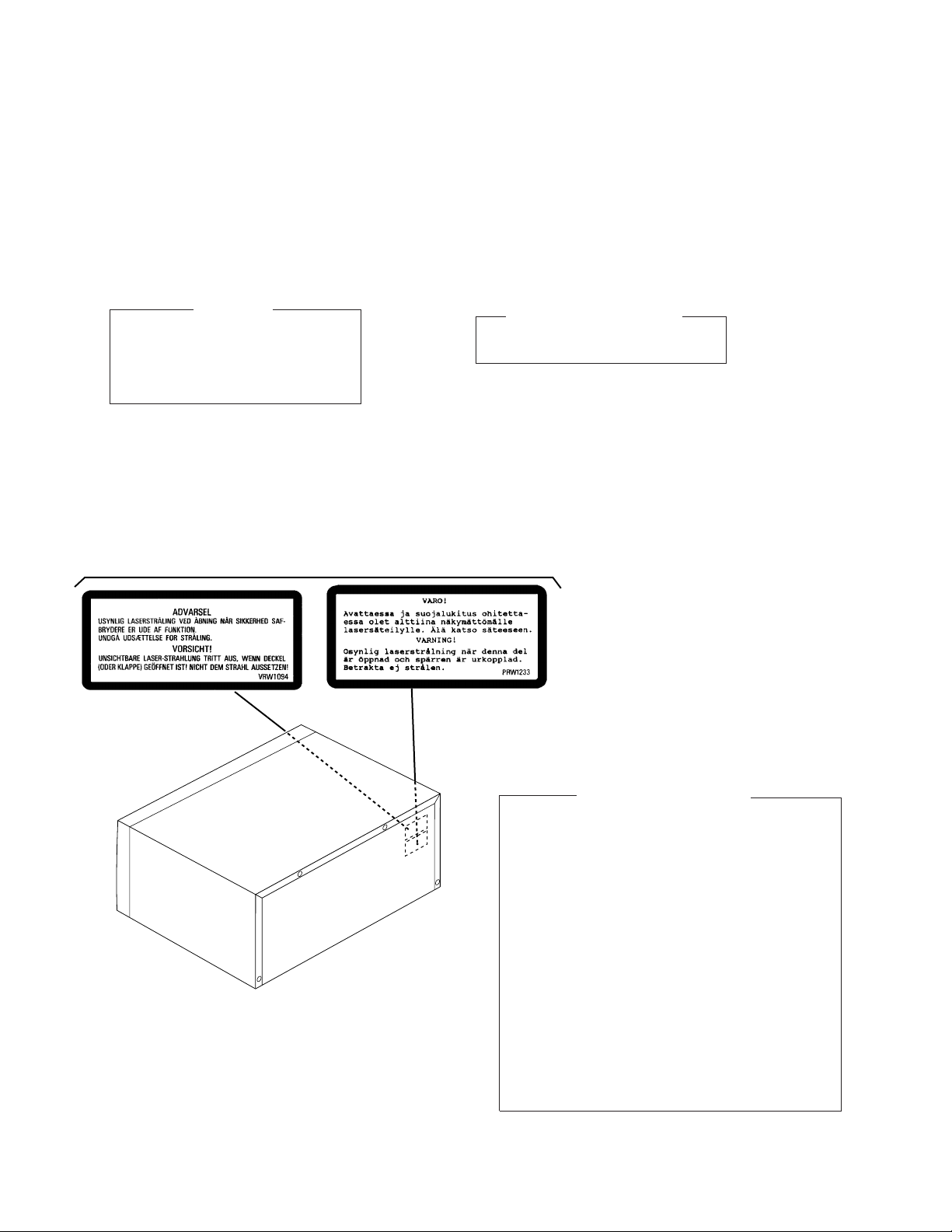
THIS PIONEER APPARATUS CONTAINS
LASER OF CLASS 1.
SERVICING OPERATION OF THE APPARATUS
SHOULD BE DONE BY A SPECIALLY
INSTRUCTED PERSON.
LABEL CHECK
IMPORTANT
PD-F1007/MY
LASER DIODE CHARACTERISTICS
MAXIMUM OUTPUT POWER: 7 mw
WAVELENGTH: 780 – 785 nm
Additional Laser Caution
1.Laser Interlock Mechanism
The position of the switch (VSK1011) for detecting
loading state is detected by the system microprocessor,
and the design prevents laser diode oscillation when
the switch (VSK1011) is not on CLMP terminal side
REAR
(CLMP signal is OFF or high level).
Thus, the interlock will no longer function if the switch
(VSK1011) is deliberatery set to CLMP terminal side. (low
level)
The interlock also does not function in the test mode *.
Laser diode oscillation will continue, if pin 33 of
CXA1782CQ (IC151) on the MOTHER BOARD ASSY
is connected to GND, or pin 89 of IC351 (LDON) is
connected to low level (ON), or else the terminals of
Q151 are shorted to each other (fault condition).
2.When the cover is opened, close viewing of the
objective lens with the naked eye will cause exposure
to a Class 1 laser beam.
∗ Refer to page 35 .
2
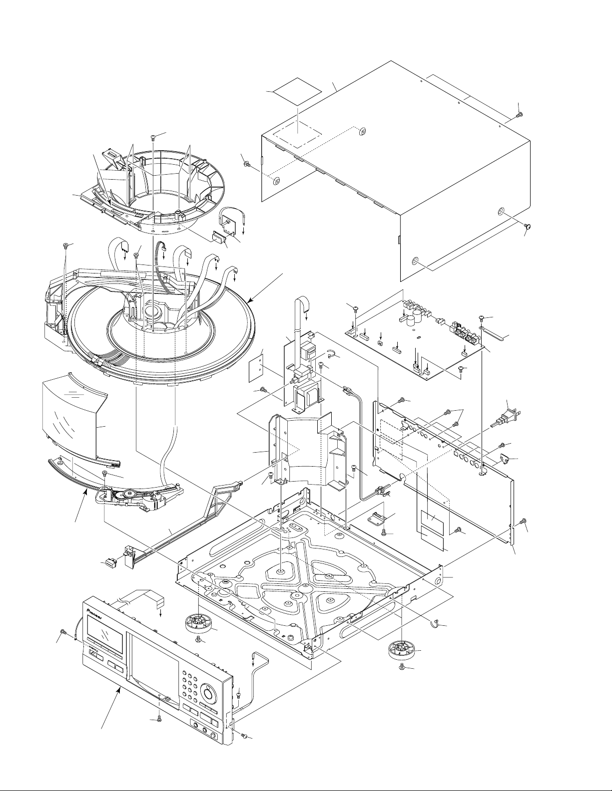
2. EXPLODED VIEWS AND PARTS LIST
NOTES : Parts marked by “ NSP ” are generally unavailable because they are not in our Master Spare Parts List.
The mark found on some component parts indicates the importance of the safety factor of the part.
Therefore, when replacing, be sure to use parts of identical designation.
Screw adjacent to mark on the product are used for disassembly.
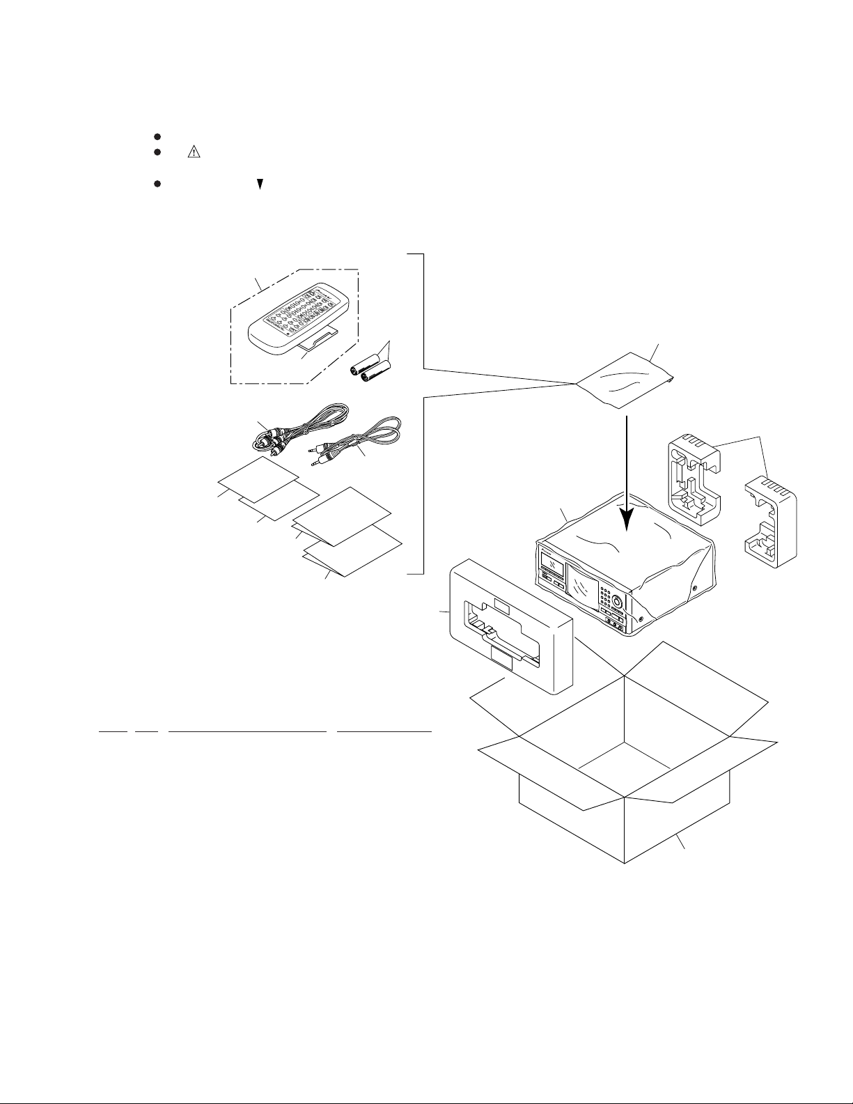
2.1 PACKING
8
PD-F1007
9
12
11
13
14
6
7
PACKING PARTS LIST
Mark No. Description Part No.
10
5
2
4
1
1 Styrol Protector F PHA1325
2 Styrol Protector R PHA1326
3 Packing Case PHG2368
4 Packing Sheet RHC1023
5 Polyethylene Bag Z21–038
(0.03 × 230 × 340)
6 Operating Instructions PRD1052
(English/French/German/Italian)
7 Operating Instructions PRE1279
(Dutch/Swedish/Spanish/Portuguese)
8 Remote Control Unit PWW1139
(CD-PD094)
9 Battery Cover AZA7204
NSP 10 Dry Cell Batteries (R6P, AA) VEM–013
11 Control Cable (L=1 m) PDE1247
12 Audio Cable (L=1 m) PDE1248
NSP 13 Warranty Card ARY7022
14 KEY Board Label PRW1527
3
3
PD-F1007
2.2 EXTERIOR (1/2)
∗
2
14
(1/2)
6
6
C
8
19
22
21
20
F
3
D
E
15
G
Refer to " 2.3 EXTERIOR (2/2)".
21
H
25
22
I
2
A
C
23
20
I
D
E
F
G
B
H
22
13
1
22
Hood Base Assy
20
16
17
20
11 (1/2)
6
20
12
20
A
10
20
B
20
4
11 (2/2)
20
20
20
24
20
18
7
23
10
20
5
20
14
(2/2)
20
9
Refer to " 2.5 FRONT PANEL
ASSY SECTION".
4
20
20
PD-F1007
No. 14: Center Pole
Cut
14 (1/2)
No. 11: Trans Cover
11(1/2)
Cut
14 (2/2)
Cut
11(2/2)
Hood Base Assy Section
32
∗
2
31
35
27
30
28
35
33
∗
2
29
∗
1
26
34
EXTERIOR (1/2) PARTS LIST
Mark No. Description Part No.
1 MAIN BOARD ASSY PWZ3823
2 POWER BOARD ASSY PWZ3853
NSP 3 LED BOARD ASSY PWZ3867
4 Strain Relief CM–22B
5 AC Power Cord VDG1061
6 Screw C PBA1106
NSP 7 Under Base PNA2421
8 Bonnet Case PYY1255
9 Rear Base PNA2491
10 Insulator PNW2766
11 Trans Cover PNW2802
12 Joint PNW2805
13 Cord Clamper RNH–184
14 Center Pole PNW2792
15 CR Lens PNW2816
16 POWER Button PAC1884
17 Hood PNW2793
18 Caution Label (HE) PPW1233
19 Caution Label PRW1517
20 Screw BBZ30P080FZK
21 Screw FBT40P080FZK
22 Screw IPZ30P080FMC
23 Binder ZCA–SKB90BK
24 Caution Label VRW1094
25 Screw Cover PNM1340
Mark No. Description Part No.
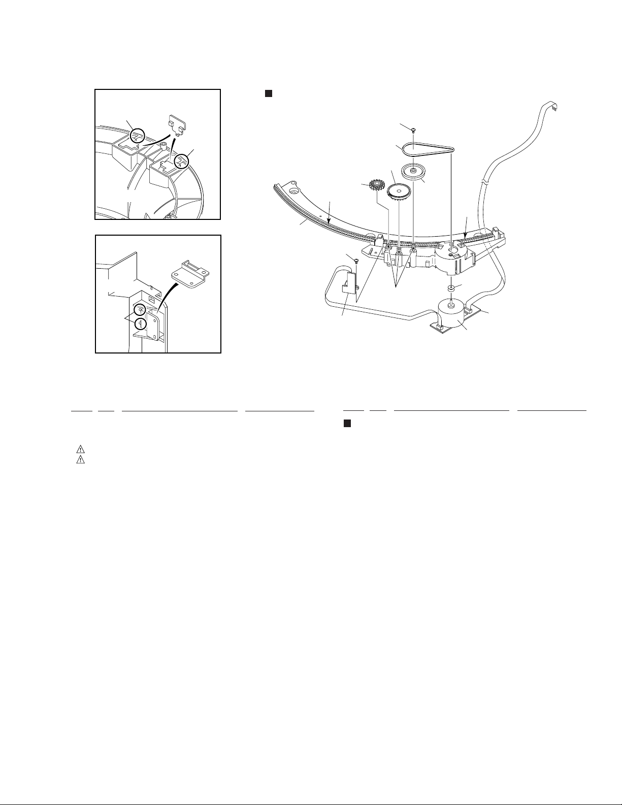
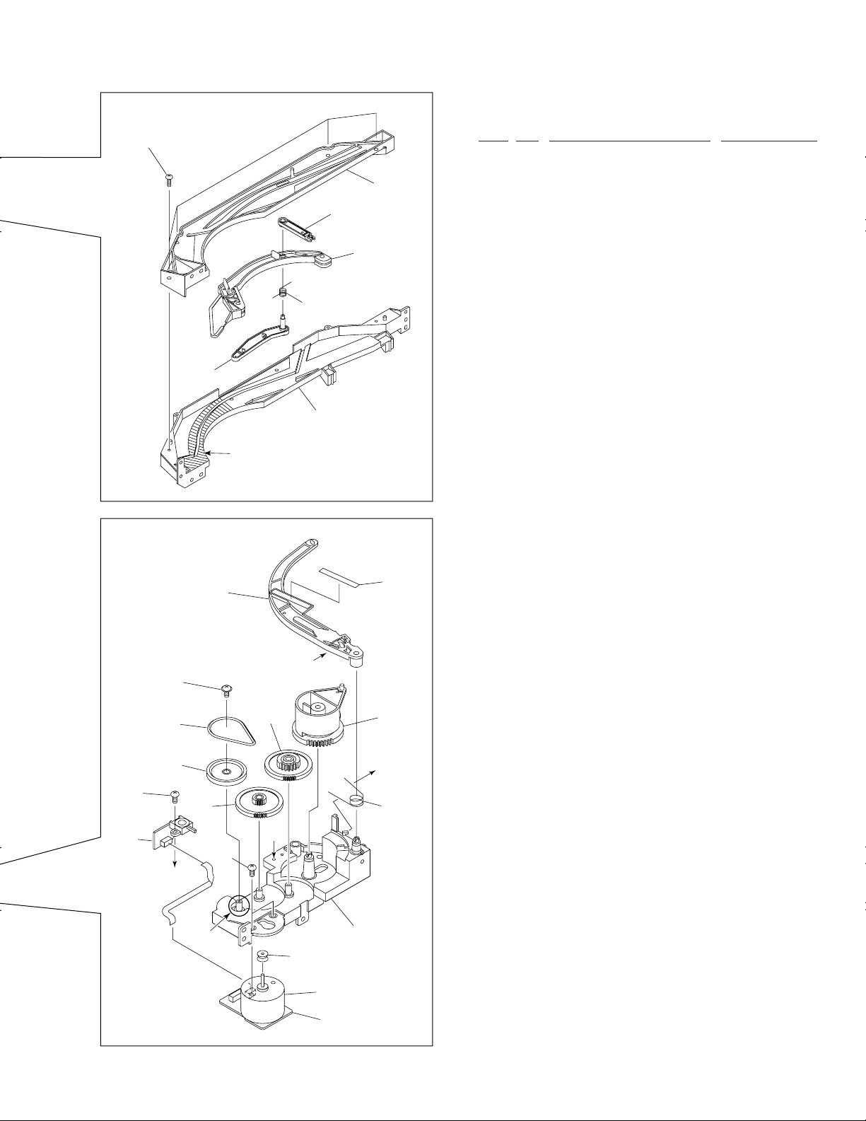
Hood Base Assy Section
NSP 26 DOOR MOTOR BOARD ASSY PWZ3863
NSP 27 DOOR SW BOARD ASSY PWZ3865
28 Belt PEB1300
29 Motor Pulley PNW1634
30 Gear AW PNW2906
31 Hood Base PNW2791
32 Gear M1 PNW2800
33 Gear Pulley VNL1662
34 Slider Motor VXM1033
35 Screw IPZ20P080FMC
∗1 Froil 397 (for service) GYA1001
∗2 Ha Narl PN955R (for service) GEM1016
∗2 Ha Narl PN955R (for service) GEM1016
5
PD-F1007
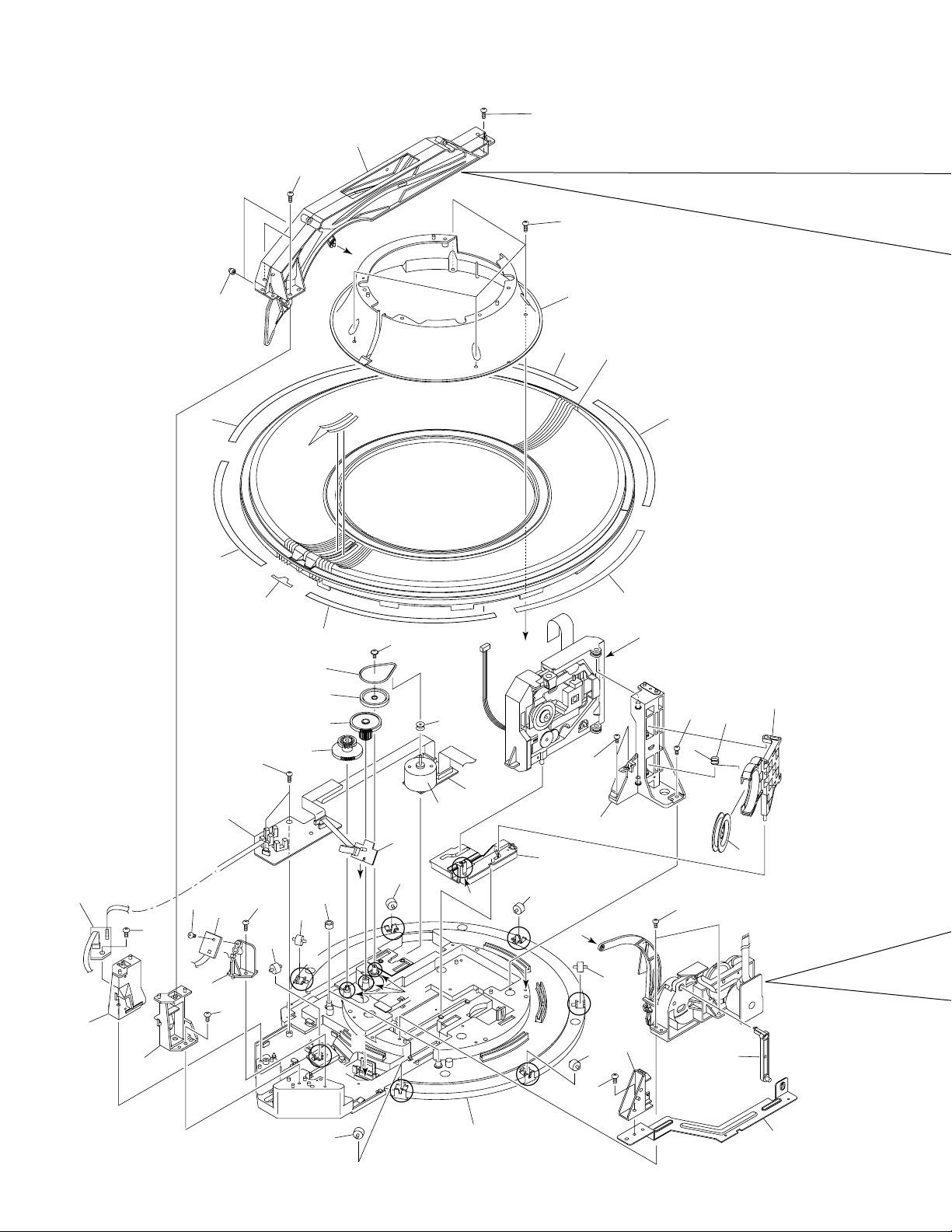
2.3 EXTERIOR (2/2)
11
44
52
46
53
52
52
B
40
44
33
44
38
44
52
B
47
∗
20
32
44
Refer to " 2.4 FLOAT BASE
ASSY SECTION".
52
52
32
21
8
15
1
37
28
30
45
44
9
10
35
52
32
36
32
42
∗
1
52
1
7
50
52
6
41
50
51
31
43
5
32
C
∗
1
A
2
19
∗
2
32
∗
1
A
∗
1
C
39
32
∗
1
∗
1
∗
1
34
6
52
24
23
12
26
[ Apply the Guide R (No. 27) also
∗
2
at the same position.]
25
27
PD-F1007
EXTERIOR (2/2) PARTS LIST
Mark No. Description Part No.
NSP 1 SENSOR BOARD ASSY PWZ3781
NSP 2 SELECT BOARD ASSY PWZ3785
NSP 3 LOADING BOARD ASSY PWZ3788
NSP 4 LOADING SW BOARD ASSY PWZ3790
NSP 5 RADIATE BOARD ASSY PWZ3791
NSP 6 RECEIVE BOARD ASSY PWZ3792
NSP 7 VOLUME BOARD ASSY PWZ3866
8 Clamp Spring ABH7107
9 Loading Belt AEB7029
10 Gear Pulley B ANW7062
11 Roller B ANW7075
NSP 12 Arm Spring PBH1225
13 L Arm Spring PBH1226
14 Sheet PED1028
15 Clamper PNW2743
16 Gear 1 PNW2819
17 Gear 2 PNW2820
18 Gear Holder PNW2822
19 Slider Cam PNW2823
20 Clamp Support PNW2826
21 Clamp Holder PNW2827
22 Drive Arm PNW2829
NSP 23 Link PNW2830
NSP 24 L Slider PNW2831
NSP 25 L Arm PNW2832
22
Note) Tightening Torque: 2 kg·cm
51
9
10
49
4
16
48
a
∗
1
17
26 Guide L PNW2833
14
b
29
b
13
a
18
31
43
27 Guide R PNW2834
28 Link L PNW2844
29 Drive Cam PNW2873
30 Lock Plate PNA2438
31 Motor Pulley PNW1634
32 Roller PNW2647
33 Disc Rack PNW2790
34 Rack Base PNW2835
35 ST Gear 0.6 PNW2836
36 ST Gear 1.0 PNW2837
37 Disc Divider PNW2838
38 Guide Support L PNW2839
39 Guide Support R PNW2840
40 Disc Guard PNW2841
41 Sensor Stay PNW2842
42 Guide Roller PNW2843
43 Slider Motor VXM1033
44 Rack Label PAM1770
45 S Label PAM1771
46 +1 Label PRW1507
47 Screw BBZ30P080FZK
48 Screw BMZ26P040FZK
49 Screw BPZ26P060FMC
50 Screw BPZ30P100FCU
51 Screw IPZ20P080FMC
52 Screw PPZ30P080FMC
53 Arm Assy PXA1615
3
∗1 Froil 397 (for service) GYA1001
∗2 Ha Narl PN955R (for service) GEM1016
7
PD-F1007
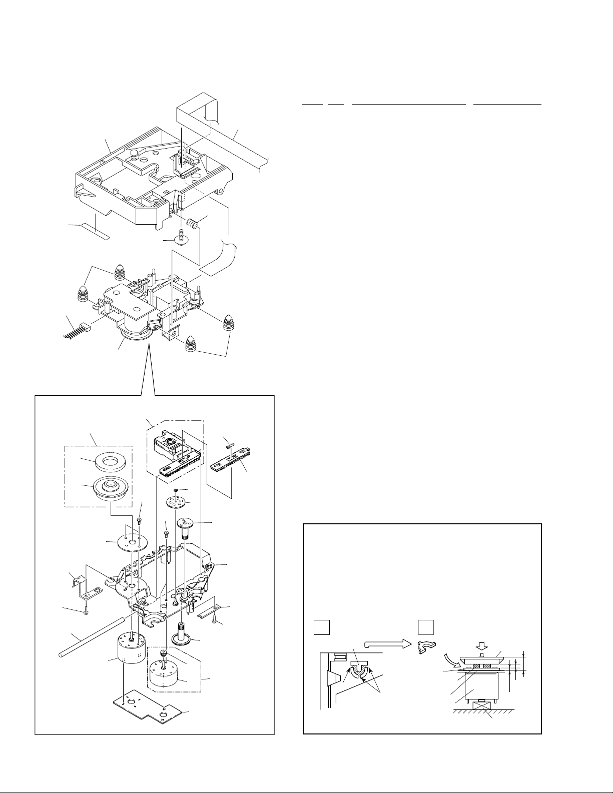
2.4 FLOAT BASE ASSY SECTION
FLOAT BASE ASSY SECTION PARTS LIST
Mark No. Description Part No.
33
32
29
26
31
27
28
29
30
1 Gear 1 PNW2052
2 Gear 2 PNW2053
3 Gear 3 PNW2054
4 Carriage Base PNW2699
5 Pickup Assy - S PEA1335
6 D.C. Motor Assy (SPINDLE) PEA1235
7 Carriage DC Motor Assy PEA1246
8 Pinion Gear PNW2055
9 Carriage DC Motor/0.3W PXM1027
10 Disc Table Assy PEA1314
11 Mechanism Board Assy PWX1192
12 Guide Bar PLA1094
13 …………
14 Screw JFZ17P025FZK
15 Screw JFZ20P040FMC
16 Washer WT12D032D025
17 Clamp Magnet PMF1014
18 Yoke M PNB1312
NSP 19 Disc Table PNW2410
NSP 20 Float Angle ANB7020
21 Gear Stopper PNB1303
22 Screw BPZ20P060FMC
23 Screw BPZ26P100FMC
24 PU Rack Spring ABH7077
25 Rack Holder PNW2056
23
20
12
17
19
10
18
15
5
24
25
16
3
14
2
4
26 Float Base PNW2828
27 Screw ABA7009
28 Float Spring ABH7049
29 Float Rubber AEB7028
30 16P F·F·C/30V PDD1185
NSP 31 Servo Mechanism Assy GM PXA1591
32 Connector Assy (4P) RDE1043
33 Sheet PED1028
How to Install the Disc Table
1
Use nipper or other tool to cut the three sections marked
A
in figure 1. Then remove the spacer
2
While supporting the spindle motor shaft with the
stopper, put spacer on top of the yoke M, and stick the
disc table on top (takes about 9kg pressure). Detach the
21
22
1
6
8
7
9
11
spacer.
1
Spacer
A
Float Base
2
Yoke M
Spacer Setting
Position
A
Carriage Base
Spindle Motor
(Pressure of about 9 kg)
Spacer
Disc Table
1.2mm
Stopper
0.9mm
±0.05mm
6.9mm
8
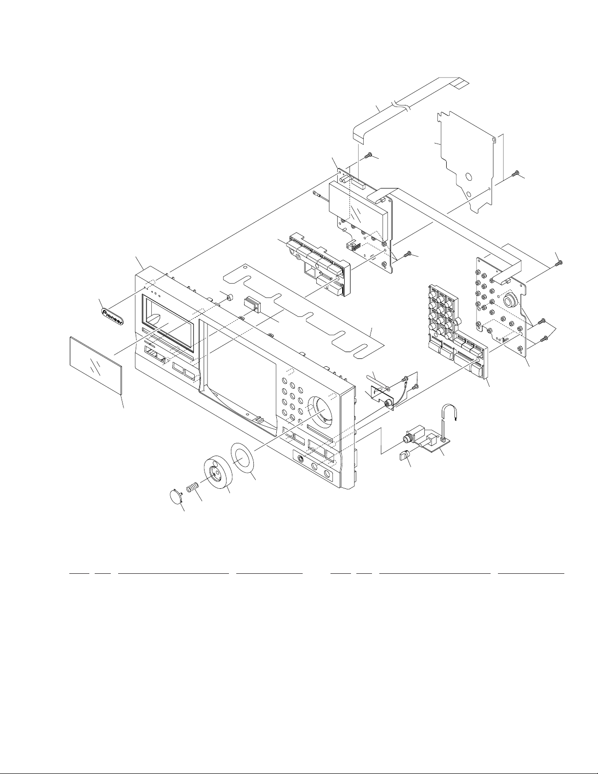
2.5 FRONT PANEL ASSY SECTION
PD-F1007
4
14
1
19
19
5
16
9
10
15
17
12
7
11
8
13
22
20
19
21
6
3
18
19
19
2
FRONT PANEL ASSY SECTION PARTS LIST
Mark No. Description Part No.
1 DISPLAY BOARD ASSY PWZ3840
NSP 2 FUNCTION BOARD ASY PWZ3847
NSP 3 HEADPHONE BOARD ASSY PWZ3860
4 18P F·F·C/30V PDD1188
5 MODE Button PAC1880
6 PLAY Button PAC1881
7 Jog Dial PAC1882
8 ENTER Button PAC1883
9 Name Plate PAM1776
10 Display Window PAM1796
11 Enter Spring PBH1228
12 Jog Sheet PEC1042
Mark No. Description Part No.
13 FC Cover PNM1323
14 PCB Cover PNM1324
15 LED Lens PNW2019
16 Operation Panel PNW2909
17 Sensor Lens PNW2804
18 Rotary Knob RAC1903
19 Screw PPZ30P100FMC
20 KEY BOARD ASSY PWZ3836
21 Screw PPZ30P050FMC
22 Cord clamper RNH-184
9
1
PD-F1007
3. SCHEMATIC DIAGRAM
A
Note : When ordering service parts, be sure to refer to "EXPLODED VIEWS and PARTS LIST" or "PCB PARTS LIST".
A
A
-a
-c
A
-a
A
A
A
-b
-d
-b
Large size
SCH diagram
Guide page
23
3.1 MECHANISM BOARD, DOOR MOTOR BOARD,
DOOR SW BOARD, LED BOARD and PICKUP
ASSEMBLIES
SERVO MECHANISM ASSY
(PXA1591)
SPINDLE
MOTOR
ASSY
PEA1235
4
SIGNAL ROUTE
B
A
-a
Detailed page
A
-b
(F)
: FOCUS SERVO LOOP
(T)
: TRACKING SERVO LOOP
(C)
: CARRIAGE SERVO LOOP
(S)
: SPINDLE DRIVE
CARRIADGE
MOTOR
ASSY
PEA1246
K
CN207
DOOR SW
C
BOARD ASSY
(PWZ3865)
C
DOOR MOTOR
B
BOARD ASSY
(PWZ3863)
DOOR MOTOR
VXM1033
K
CN205
MECHANISM
A
BOARD ASSY
(PWX1192)
PICKUP ASSY
(PEA1335)
LED BOARD ASSY
D
(PWZ3867)
K
CN202
K
CN208
D
10
1234
(T)
(T)
(F)
(F)
1
234
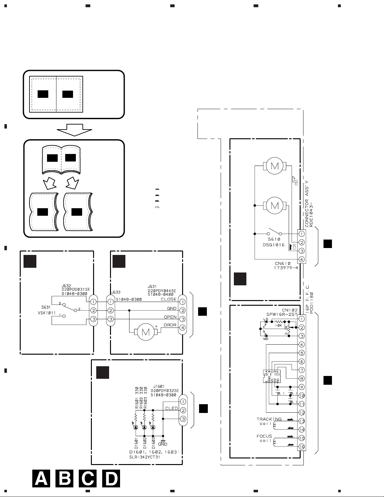
PD-F1007
3.2 LOADING SW, LOADING BOARD, SENSOR BOARD, RECIEVE BOARD, RADIATE
BOARD and SELECT BOARD ASSEMBLIES
LOADING
F
BOARD
ASSY
(PWZ3788)
LOADING SW ASSY
E
(PWZ3790)
REAF SW
VSK1011
LOADING MOTOR
VXM1033
SENSOR BOARD
G
ASSY
(PWZ3781)
100k
100k
1.5k
150
J605
D20PDY0310E
VOLUME BOARD ASSY
P
(PWZ3866)
22k
VR601
CN605 CN604
52147–0310 ×2
J604
D20PDY0315E
I
K
CN203
RADIATE
BOARD
ASSY
(PWZ3791)
RECIEVE
H
BOARD
ASSY
(PWZ3792)
A
B
C
K
CN204
SELECT MOTOR
VXM1033
SELECT
J
BOARD
ASSY
(PWZ3785)
11
1
2
3
4
D
1
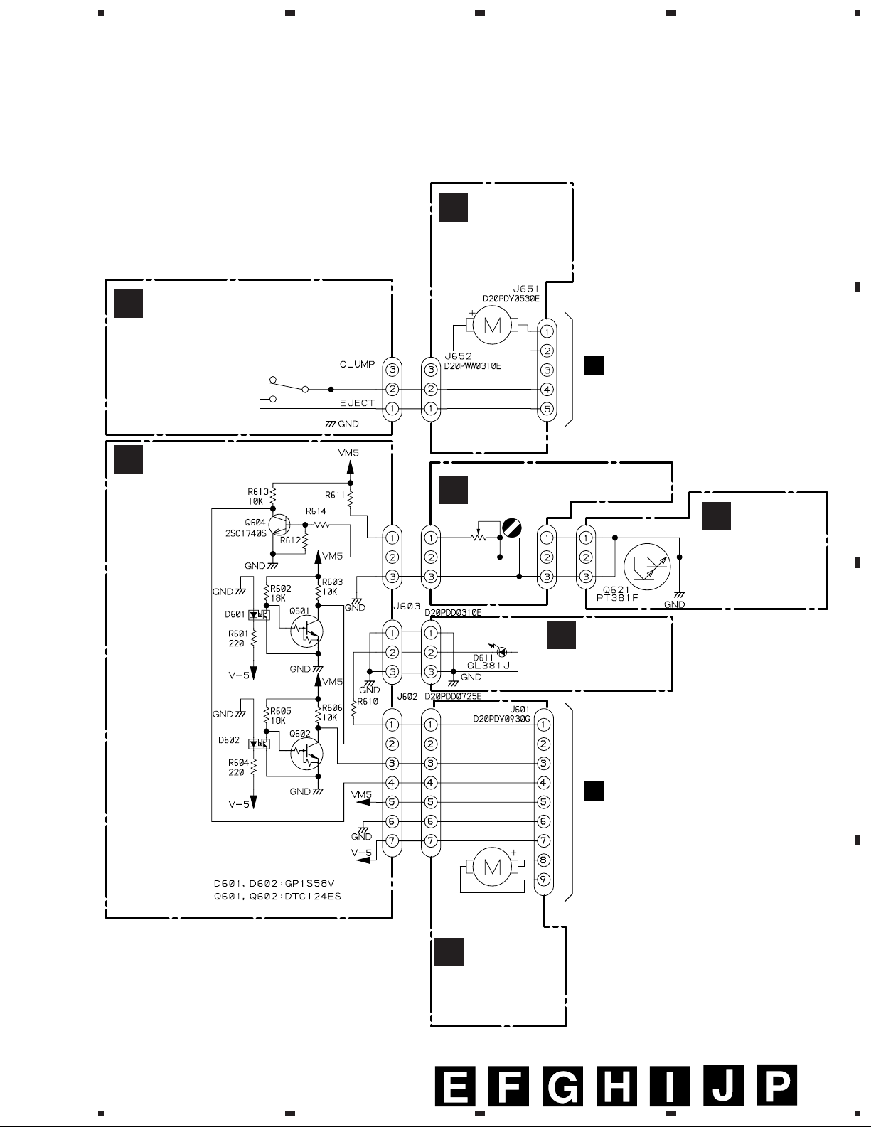
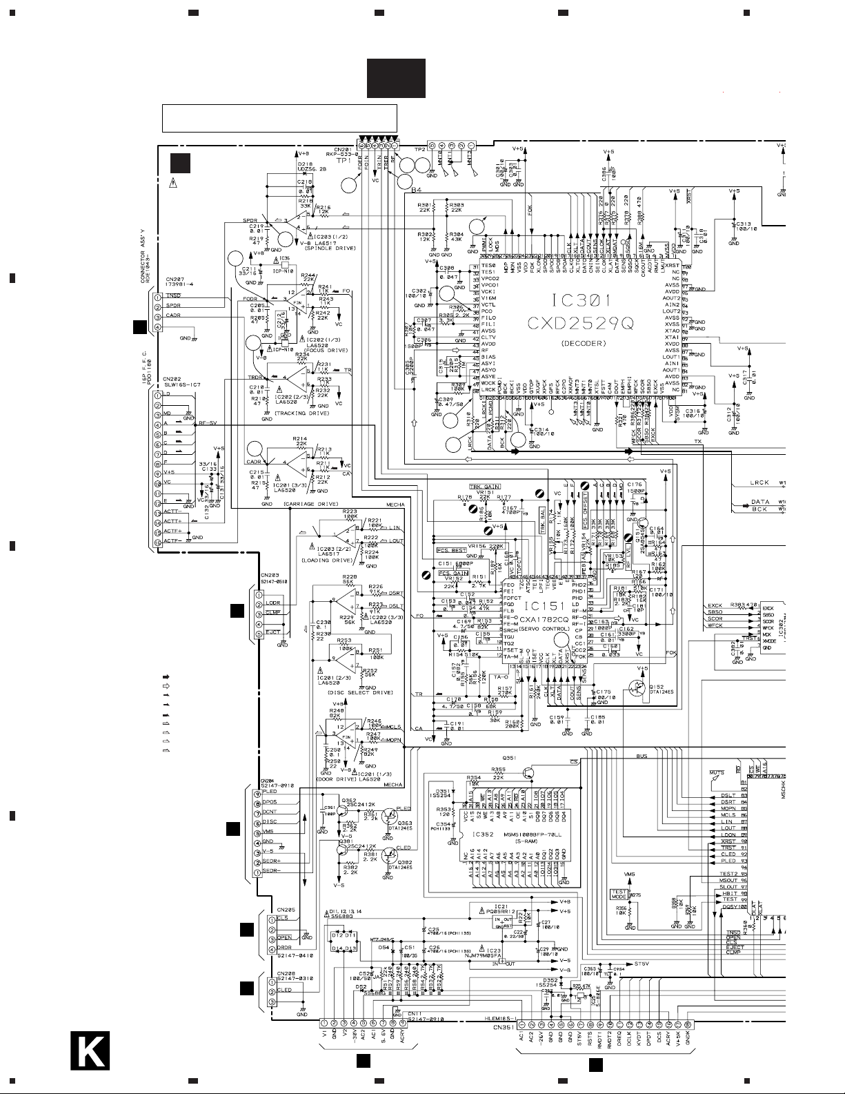
PD-F1007
23
4
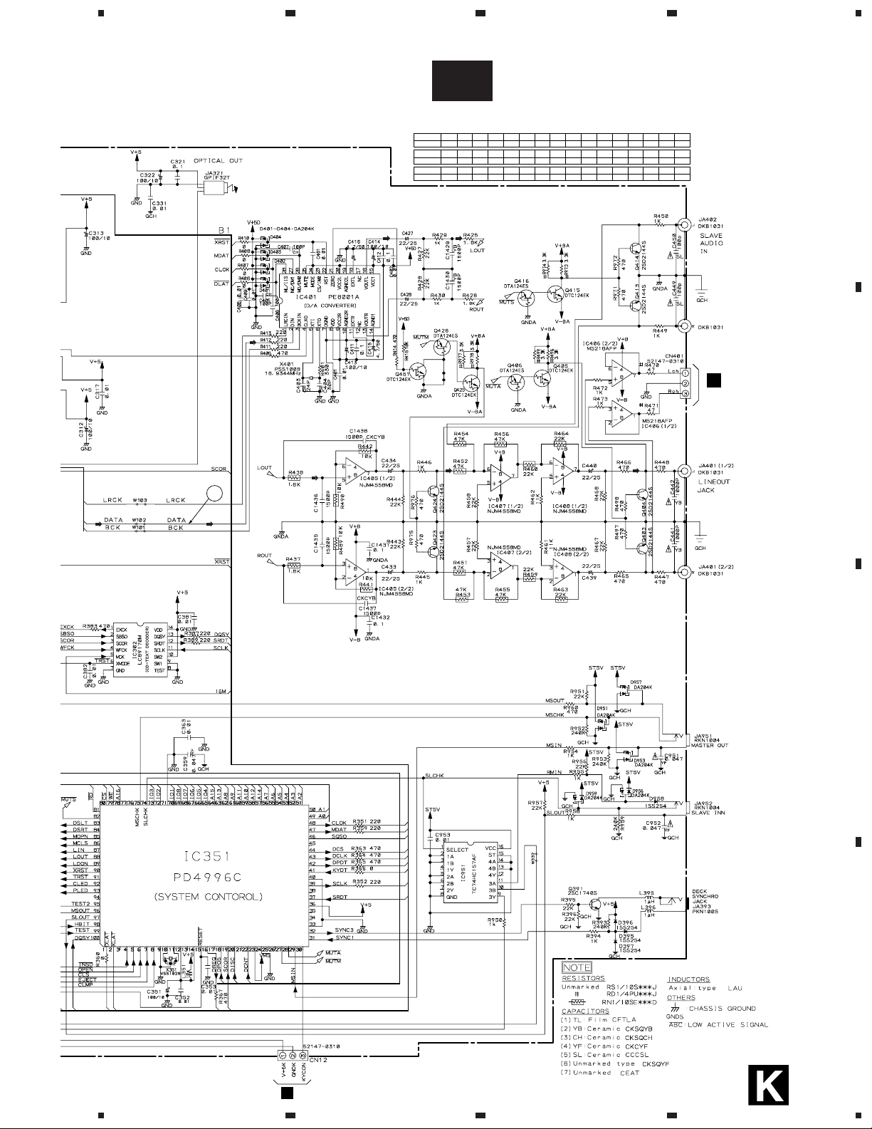
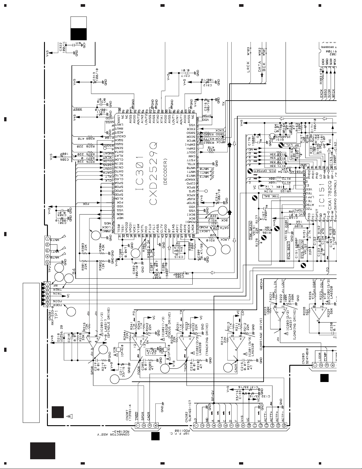
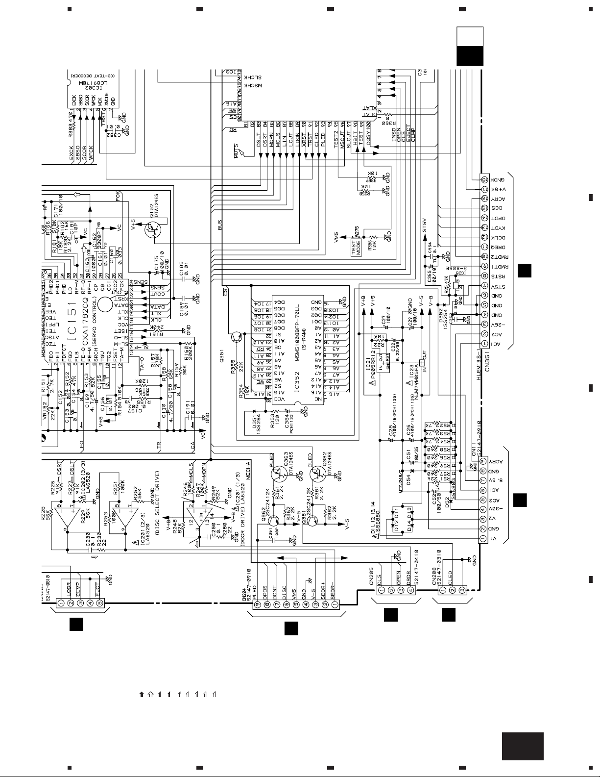
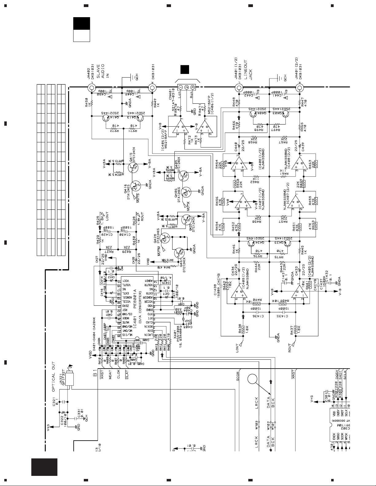
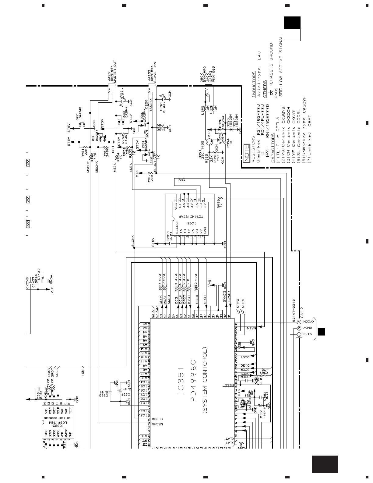
3.3 MAIN BOARD ASSY
CAUTION : FOR CONTINUED PROTECTION AGAINST RISK OF FIRE,
REPLACE ONLY WITH SAME TYPE NO. ICP-N10, MFD BY
ROHM CO., FOR IC35 AND IC36.
A
K
CN610
A
B
(F)
(F)
(F)
(F)
MAIN
BOARD
ASSY
(PWZ3823)
5
-0.7V
6
8
(F)
0V
(T)
0V
0.2V
K-a
2 23
3
1.8V
1.8V
(S)
(S)
(S)
7
1.6V
(F)
1.6V
1.6V
(T)
1.6V
1.7V
(C)
4
33
53
18
19
16
to PICUP ASSY
(T)
(T)
F
J651
1.7V
(T)
0V
(L)
(SEL)
0V
(L)
(L)
0V
(SEL)
(SEL)
(F)
(F)
(F)
(F)
(F)
(T)
23
SIGNAL ROUTE
C
: AUDIO SIGNAL
: EFM SIGNAL
(F)
: FOCUS SERVO LOOP
(T)
: TRACKING SERVO LOOP
(C)
: CARRIAGE SERVO LOOP
(S)
: SPINDLE DRIVE
(L)
: LOADING DRIVE
(D)
: DOOR DRIVE
(SEL)
: SELECT DRIVE
(T)
0V
(D)
0V
(D)
(D)
0V
(C)
2SD2144S
J
J601
B
D
J631
D
J1601
12
1234
O
J11
L
J701
5
678
PD-F1007
K-b
IC301(CXD2529Q) :PLAY MODE
1 2 3 - 4 7 8 9 10 11 12 13 14 16 17 23 24 25
PIN No.
5
Voltage(V)
PIN No.
26 27 38 39 40 41 42 43 44 45 46 47 48 50-55 56 57
5
Voltage(V)
PIN No.
61 71 75 78 79 82 83 87 88 89-9084-86 91-92 93-95 9796 100
5
Voltage(V)
4.7
2.5
3.1 3.12.5 2.5 0.9 2.5 2.5 2.5
2.6-2.7
00505 05 0 50 5
2.5 2.5 2.5 2.5
55550 00
4.4 4.7 4.7 4.71.2-1.41.2-1.3
55
0 50
0.05
A
N
J501
B
10
C
D
O
J71
5
6
7
8
13
PD-F1007
MAIN
BOARD
ASSY
(PWZ3823)
K
F
J651
A
CN610
to PICUP ASSY
1.8V
1.8V
-0.7V
1.6V
1.6V
0V
1.6V
1.6V
0V
1.7V
1.7V
0.2V
0V
0V
0V
CAUTION : FOR CONTINUED PROTECTION AGAINST RISK OF FIRE,
REPLACE ONLY WITH SAME TYPE NO. ICP-N10, MFD BY
ROHM CO., FOR IC35 AND IC36.
(S)
(S)
(S)
(F)
(F)
(F)
(F)
(F)
(F)
(T)
(T)
(T)
(T)
(C)
(L)
(L)
(L)
(SEL)
(SEL)
(SEL)
(F)
(F)
(F)
(F)
(F)
(T)
(T)
7
5
6
8
2 23
4
3
33
53
18
19
16
K-bK-a
A
1
23
4
B
C
D
14
K-a
1234
5
B
J631
J
J601
F
J651
D
J1601
O
J11
L
J701
0V
0V
0V
2SD2144S
SIGNAL ROUTE
: AUDIO SIGNAL
: EFM SIGNAL
: FOCUS SERVO LOOP
: TRACKING SERVO LOOP
: CARRIAGE SERVO LOOP
: SPINDLE DRIVE
: LOADING DRIVE
: DOOR DRIVE
: SELECT DRIVE
)
(SEL)
(SEL)
(SEL)
(D)
(D)
(D)
(F)
(T)
(C)
23
K-bK-a
678
PD-F1007
A
B
C
5
D
6
K-a
7
8
15
PD-F1007
N
J501
IC301(CXD2529Q) :PLAY MODE
PIN No.
Voltage(V)
PIN No.
Voltage(V)
PIN No.
Voltage(V)
1 2 3 - 4 7 8 9 10 11 12 13 14 16 17 23 24 25
26 27 38 39 40 41 42 43 44 45 46 47 48 50-55 56 57
61 71 75 78 79 82 83 87 88 89-9084-86 91-92 93-95 9796 100
5
5
5
55
55550 00
00 505 05 0 50 5
0 50
4.7
2.5
2.5 2.5 2.5 2.5
3.1 3.12.5 2.5 0.9 2.5 2.5 2.5
4.4 4.7 4.7 4.71.2-1.41.2-1.3
2.6-2.7
0.05
10
K-bK-a
A
B
1
23
4
C
D
16
K-b
1234
5
O
J71
K-b
K-a
678
PD-F1007
A
B
C
D
K-b
5
6
7
8
17
 Loading...