


KEHP-6020-R
CONTENTS
1. SAFETY INFORMATION ............................................2
2. EXPLODED VIEWS AND PARTS LIST.......................3
3. BLOCK DIAGRAM AND SCHEMATIC DIAGRAM ...10
4. PCB CONNECTION DIAGRAM ................................24
5. ELECTRICAL PARTS LIST ........................................32
6. ADJUSTMENT..........................................................36
7. GENERAL INFORMATION .......................................37
7.1 DIAGNOSIS ........................................................37
7.1.1 DISASSEMBLY ..............................................37
7.1.2 CONNECTOR FUNCTION DESCRIPTION ....38
7.2 PARTS .................................................................39
7.2.1 IC ....................................................................39
7.2.2 DISPLAY.........................................................45
7.3 OPERATIONAL FLOW CHART..........................46
7.4 CLEANING .........................................................47
8. OPERATIONS AND SPECIFICATIONS.....................48
PIONEER CORPORATION 4-1, Meguro 1-Chome, Meguro-ku, Tokyo 153-8654, Japan
PIONEER ELECTRONICS (USA) INC. P.O.Box 1760, Long Beach, CA 90801-1760 U.S.A.
PIONEER EUROPE NV Haven 1087 Keetberglaan 1, 9120 Melsele, Belgium
PIONEER ELECTRONICS ASIACENTRE PTE.LTD. 253 Alexandra Road, #04-01, Singapore 159936
C PIONEER CORPORATION 2001
K-ZZS. NOV. 2001 Printed in Japan
ORDER NO.
CRT2805
MULTI-CD CONTROL HIGH POWER CASSETTE PLAYER WITH RDS TUNER
KEH-P6020RB XN/EW
KEH-P6020RB/XN/EW
- This service manual should be used together with the following manual(s):
Model No. Order No. Mech. Module Remarks
CX-1011 CRT2406 3L
Cassette Mech. Module:Mech.Description, Disassembly, Adjustment
KEH-P6020R XN/EW
NOTE:
- This service manual does not describe the CD test mode.
For the operations in the CD test mode, refer to the CD player's Service manual.
For details, refer to "Important symbols for good services" on the next page.
2
KEH-P6020RB,P6020R
1. SAFETY INFORMATION
This service manual is intended for qualified service technicians; it is not meant for the casual do-it-yourselfer.
Qualified technicians have the necessary test equipment and tools, and have been trained to properly and safely repair
complex products such as those covered by this manual.
Improperly performed repairs can adversely affect the safety and reliability of the product and may void the warranty.
If you are not qualified to perform the repair of this product properly and safely, you should not risk trying to do so
and refer the repair to a qualified service technician.
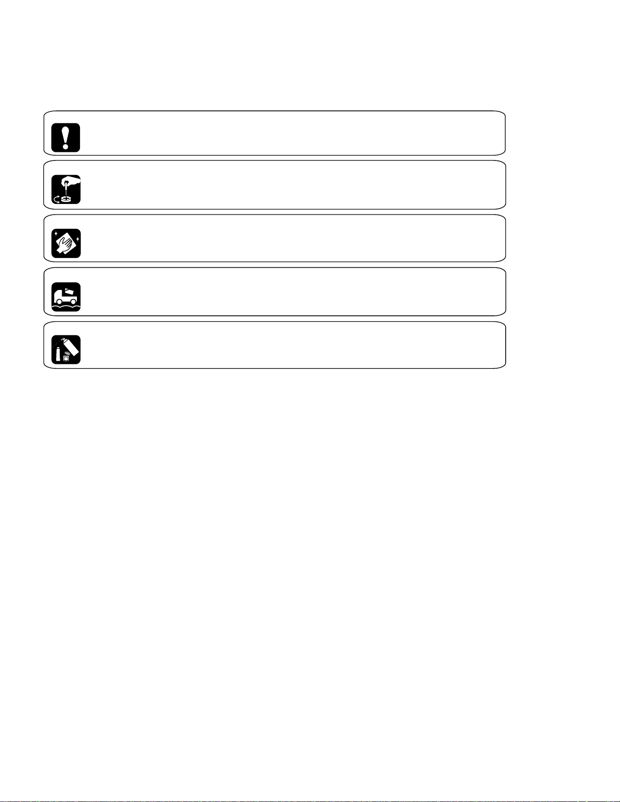
[ Important symbols for good services ]
In this manual, the symbols shown-below indicate that adjustments, settings or cleaning should be made securely.
When you find the procedures bearing any of the symbols, be sure to fulfill them:
2. Adjustments
To keep the original performances of the product, optimum adjustments or specification confirmation is indispensable.
In accordance with the procedures or instructions described in this manual, adjustments should be performed.
3. Cleaning
For optical pickups, tape-deck heads, lenses and mirrors used in projection monitors, and other parts requiring cleaning,
proper cleaning should be performed to restore their performances.
5. Lubricants, glues, and replacement parts
Appropriately applying grease or glue can maintain the product performances. But improper lubrication or applying
glue may lead to failures or troubles in the product. By following the instructions in this manual, be sure to apply the
prescribed grease or glue to proper portions by the appropriate amount.For replacement parts or tools, the prescribed
ones should be used.
4. Shipping mode and shipping screws
To protect the product from damages or failures that may be caused during transit, the shipping mode should be set or
the shipping screws should be installed before shipping out in accordance with this manual, if necessary.
1. Product safety
You should conform to the regulations governing the product (safety, radio and noise, and other regulations), and
should keep the safety during servicing by following the safety instructions described in this manual.
3
KEH-P6020RB,P6020R
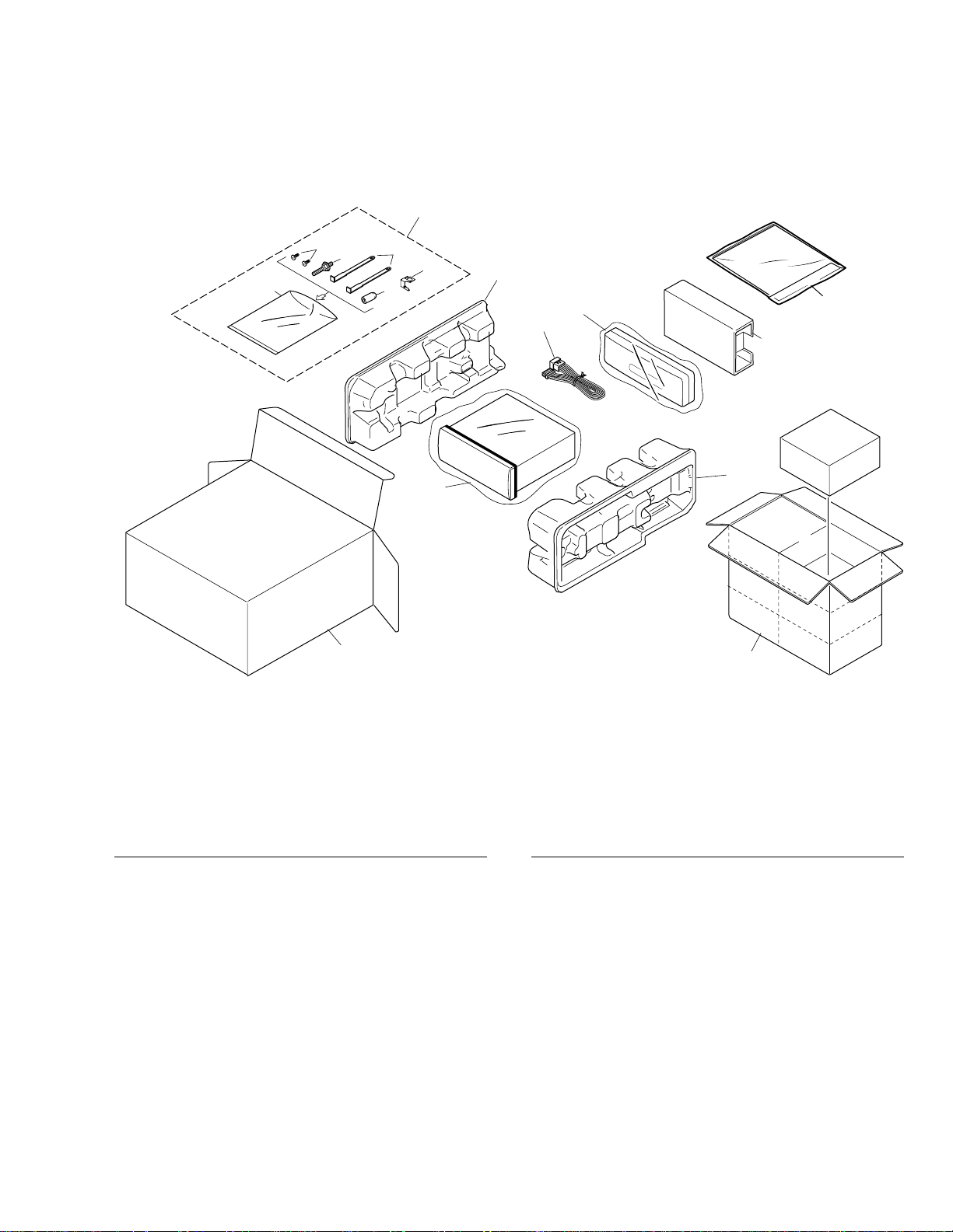
2. EXPLODED VIEWS AND PARTS LIST
2.1 PACKING
10
1
12
6
8
9
11
4
3
5
2
13
14
15
16
7
1 Cord Assy CDE6435
2 Screw CBA1002
3 Handle CNC5395
4 Bush CNV3930
* 5 Polyethylene Bag E36-615
6 Polyethylene Bag CEG-162
7-1 Polyethylene Bag CEG1116
7-2 Owner’s Manual CRD3537
7-3 Owner’s Manual CRD3538
7-4 Installation Manual CRD3553
* 7-5 Passport CRY1013
* 7-6 Warranty Card CRY1157
8 Carton
See Contrast table(2)
9 Contain Box See Contrast table(2)
10 Protector CHP2251
11 Protector CHP2252
12 Case Assy CXB3520
13 Screw BPZ20P060FZK
14 Accessory Assy CEA3062
15 Earth Plate CNC9450
16 Inner Box CHW1754
Mark No. Description Part No. Mark No. Description Part No.
(1) PACKING SECTION PARTS LIST
NOTE:
- Parts marked by “*” are generally unavailable because they are not in our Master Spare Parts List.
- Screws adjacent to
∇ mark on the product are used for disassembly.
- For the applying amount of lubricants or glue, follow the instructions in this manual.
( In the case of no amount instructions, apply as you think it appropriate.)

4
KEH-P6020RB,P6020R
Part No.
Mark No. Symbol and Description KEH-P6020RB/XN/EW KEH-P6020R/XN/EW
8 Carton CHG4561 CHG4560
9 Contain Box CHL4561 CHL4560
(2) CONTRAST TABLE
KEH-P6020RB/XN/EW and KEH-P6020R/XN/EW are constructed the same except for the following:
- Owner's Manual, Installation Manual
Model Part No. Language
KEH-P6020RB/XN/EW CRD3537 English, Spanish, German, French, Italian, Dutch
KEH-P6020R/XN/EW CRD3538
CRD3553

5
KEH-P6020RB,P6020R
6
KEH-P6020RB,P6020R
A
C
B
62
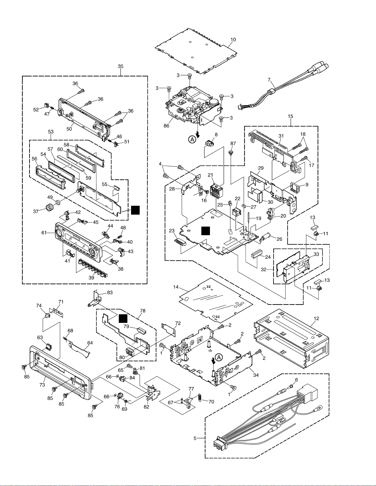
2.2 EXTERIOR

7
KEH-P6020RB,P6020R
1 Screw BMZ30P040FZK
2 Screw BMZ30P100FMC
3 Screw BSZ26P050FMC
4 Screw BSZ30P060FMC
5 Cord Assy CDE6435
6 Cap CKX-003
7 Cord Assy CDE6494
8 Fuse(10A) CEK1136
9 IC(IC361) PAL007A
10 Case CNB2686
11 Holder CNC5704
12 Holder CNC8659
13 Cushion CNM4870
14 Insulator CNM6948
15 Tuner Amp Unit
See Contrast table(2)
16 Screw ASZ26P060FMC
17 Screw BPZ26P120FMC
18 Screw BSZ26P160FMC
19 Clamper CEF1007
20 Pin Jack(CN351) CKB1035
21 Plug(CN901) CKM1330
22 Connector(CN701) CKS3408
23 Plug(CN750) CKS3537
24 Connector(CN551) CKS3568
25 Connector(CN331) CKS3598
26 Antenna Jack(CN402) CKX1056
27 Holder(CN403) CNC5399
28 Holder CNC8615
29 Holder CNC9470
30 Insulator CNM6949
31 Heat Sink CNR1583
32 FM/AM Tuner Unit CWE1562
33 Holder CNC8815
34 Chassis Unit
See Contrast table(2)
35 Detach Grille Assy See Contrast table(2)
36 Screw BPZ20P100FZK
37 Knob CAA2699
38 Button(SFEQ) CAC7221
39 Button(1-6) CAC7225
40 Button(OPEN) CAC7227
41 Button(EQ) CAC7231
42 Button(TA) CAC7232
43 Button(AUDIO) CAC7234
44 Button(LOCAL) CAC7235
45 Button(BSM) CAC7236
46 Spring CBH2430
47 Spring CBH2431
48 Spring CBH2630
49 Spring CBL1470
50 Cover CNS6740
51 Holder CNV6505
52 Holder CNV6506
53 Keyboard Unit
See Contrast table(2)
54 LCD See Contrast table(2)
55 Connector(CN1901) CKS4524
56 Holder CNC9053
57 Film
See Contrast table(2)
58 Sheet CNM7647
59 Connector CNV6440
60 Lighting Conductor CNV6441
61 Sub Grille Assy
See Contrast table(2)
62 Transistor(Q910) 2SD2396
63 Button(EJECT) CAC6839
64 Door CAT2109
65 Screw(M2x2) CBA1176
66 Washer CBF1038
67 Washer CBF1039
68 Spring CBH1838
69 Spring CBH2428
70 Spring CBH2429
71 Spring CBL1512
72 Holder CNC9096
73 Panel CNS6950
74 Pin CNV6486
75 •••••
76 Gear CNV6507
77 Arm CNV6508
78 Panel Unit CWM7627
79 Socket(CN1950) CKS3550
80 Connector(CN1951) CKS4206
81 Damper Unit CXB5070
82 Holder Unit CXB6356
83 Holder Unit CXB6357
84 Clutch Unit CXB6358
85 Screw IMS20P045FZK
86
Cassette Mechanism ModuleEXK4070
87 Screw ISS26P055FUC
(1) EXTERIOR SECTION PARTS LIST
Mark No. Description Part No. Mark No. Description Part No.
Part No.
Mark No. Symbol and Description KEH-P6020RB/XN/EW KEH-P6020R/XN/EW
15 Tuner Amp Unit CWM8019 CWM8018
34 Chassis Unit CXB8376 CXB8375
35 Detach Grille Assy CXB8413 CXB8412
53 Keyboard Unit CWM8312 CWM8311
54 LCD CAW1668 CAW1627
57 Film CNM6983 Not used
61 Sub Grille Assy CXB8622 CXB8621
(2) CONTRAST TABLE
KEH-P6020RB/XN/EW and KEH-P6020R/XN/EW are constructed the same except for the following:
8
KEH-P6020RB,P6020R
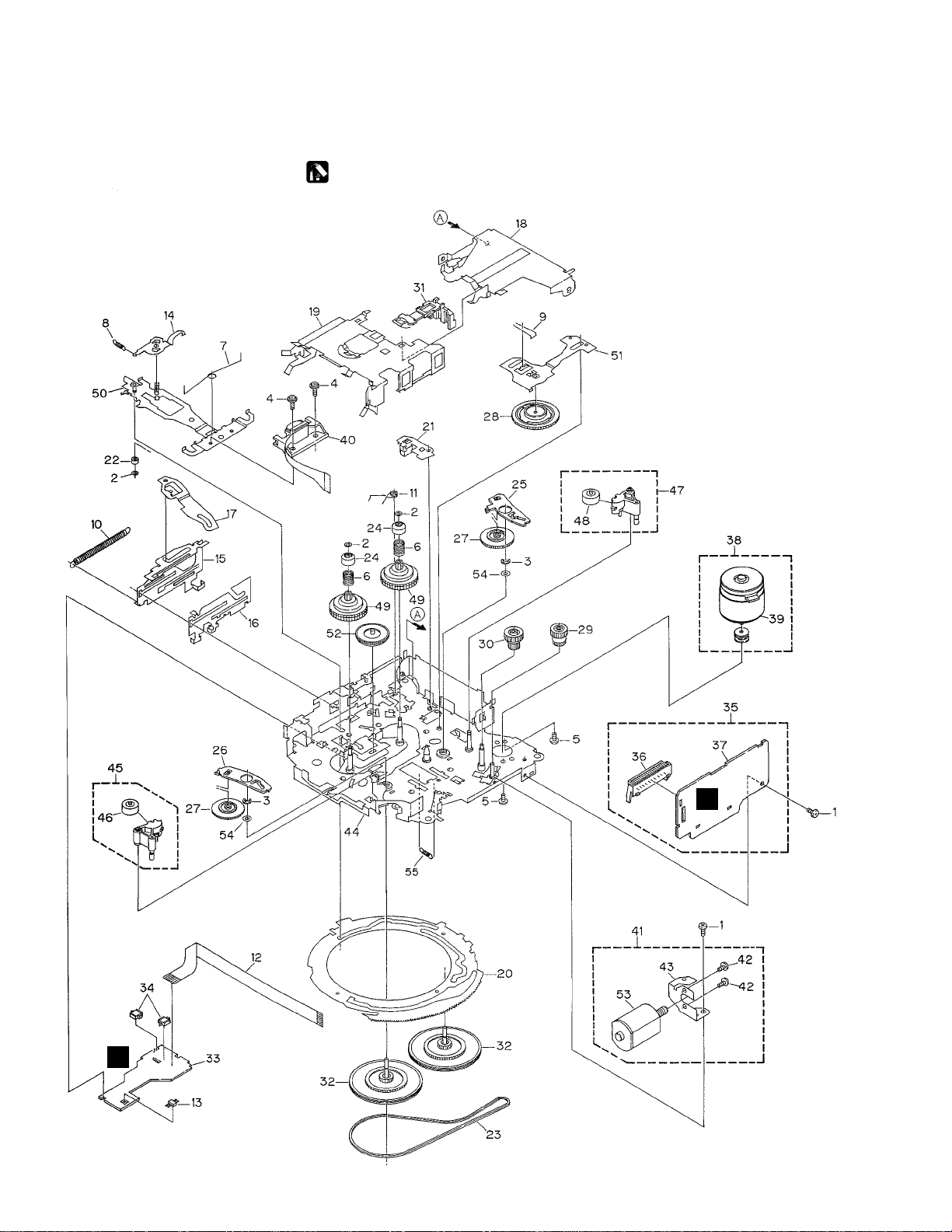
2.3 CASSETTE MECHANISM MODULE
D
E
For grease application, refer to the service manual for CX-1011 (CRT2406).

9
KEH-P6020RB,P6020R
1 Screw BSZ20P040FMC
2 Washer CBF1037
3 Washer CBG1003
4 Screw EBA1028
5 Screw CBA1037
6 Spring EBH1531
7 Spring EBH1642
8 Spring EBH1641
9 Spring EBH1626
10 Spring EBH1627
11 Spring EBH1649
12 Cord EDD1024
13 Photo-reflector(EGN1) EGN1004
14 Arm ENC1526
* 15 Lever ENC1544
16 Lever ENC1543
17 Arm ENC1532
18 Frame ENC1533
19 Holder ENC1534
20 Gear ENC1535
21 Arm ENC1550
22 Roller ENR1040
23 Belt ENT1027
24 Collar ENV1508
25 Arm ENV1539
26 Arm ENV1540
27 Gear ENV1544
28 Gear ENV1547
29 Gear ENV1560
30 Worm Wheel ENV1566
31 Lever ENV1551
32 Flywheel ENV1554
33 Gathering PCB ENX1068
34 Switch(S1,S2) ESG1007
35 Deck Unit EWM1032
36 Plug(CN251) CKS3540
37 Gathering PCB ENX1067
38 Motor Unit(M1) EXA1491
39 Motor EXM1028
40 Head Assy(HD1) EXA1592
41 Motor Unit(M2) EXA1580
42 Screw BMZ20P022FMC
43 Bracket ENC1528
44 Chassis Unit EXA1615
45 Pinch Holder Unit EXA1608
46 Pinch Roller ENV1518
47 Pinch Holder Unit EXA1607
48 Pinch Roller ENV1518
49 Reel Unit EXA1585
50 Head Base Unit EXA1611
51 Lever Unit EXA1587
52 Gear Unit EXA1596
53 Motor Unit(Service) EXX1055
54 Washer HBF-179
55 Spring EBH1537
Mark No. Description Part No. Mark No. Description Part No.
- CASSETTE MECHANISM MODULE SECTION PARTS LIST
10
KEH-P6020RB,P6020R
1
23
4
1
234
D
C
B
A
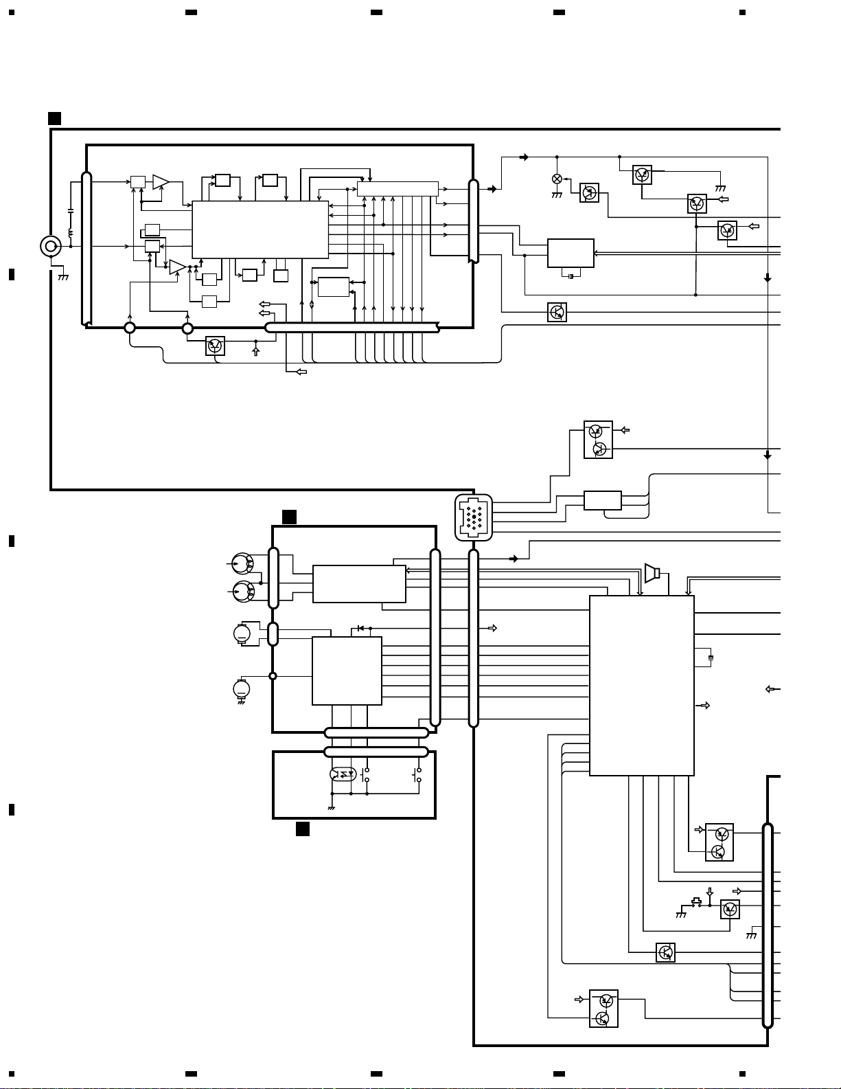
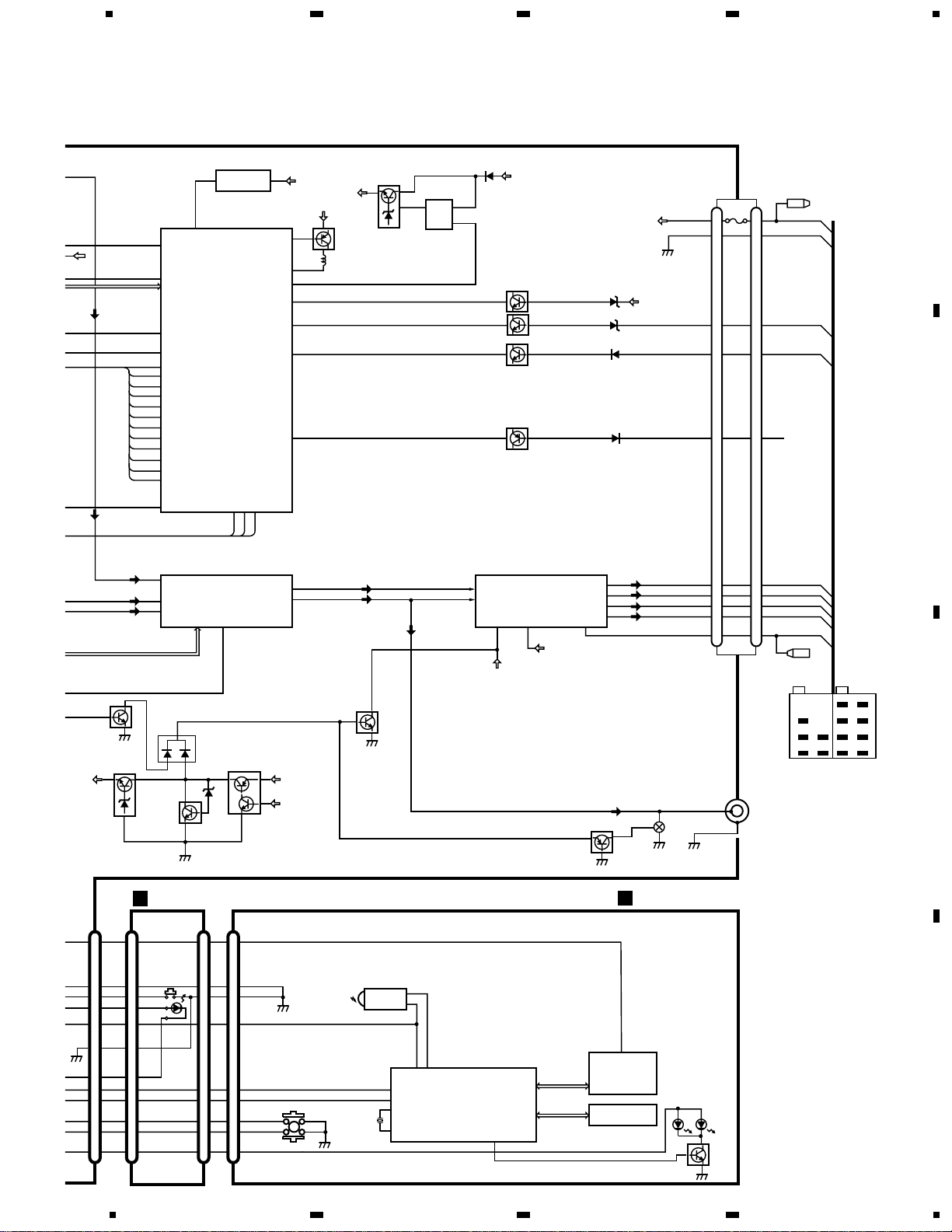
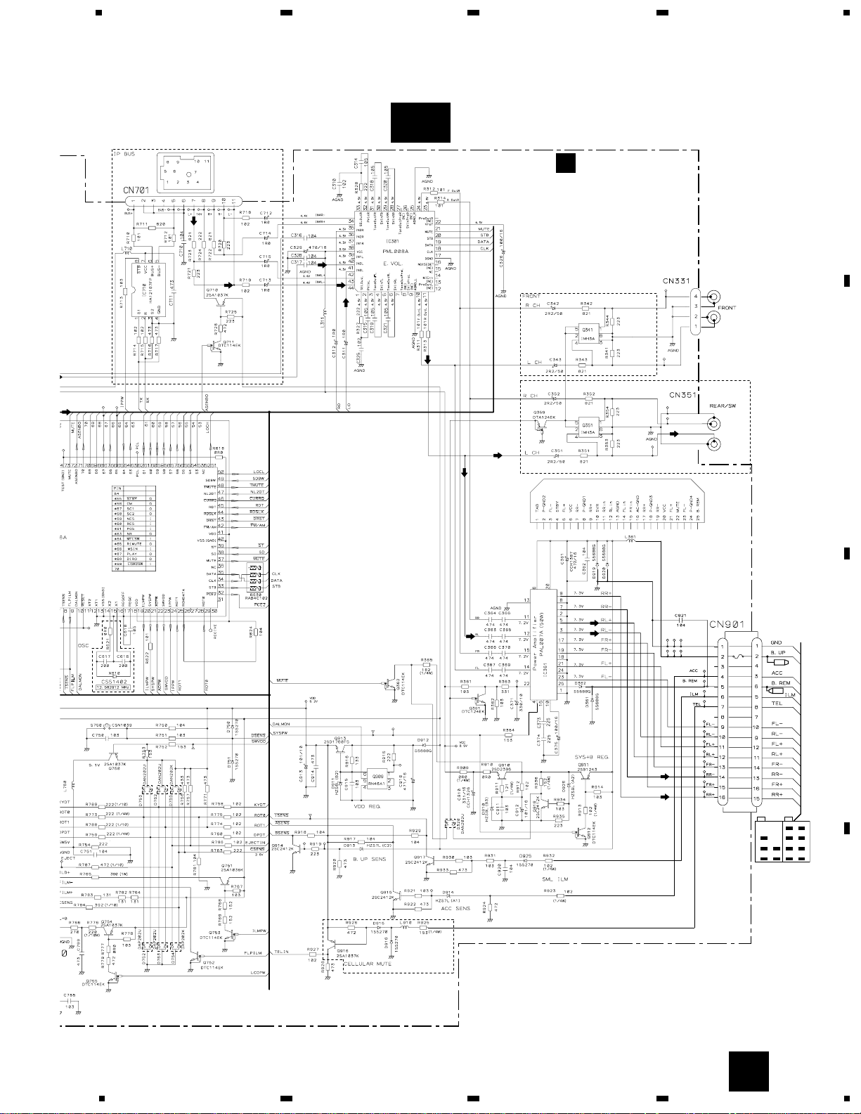
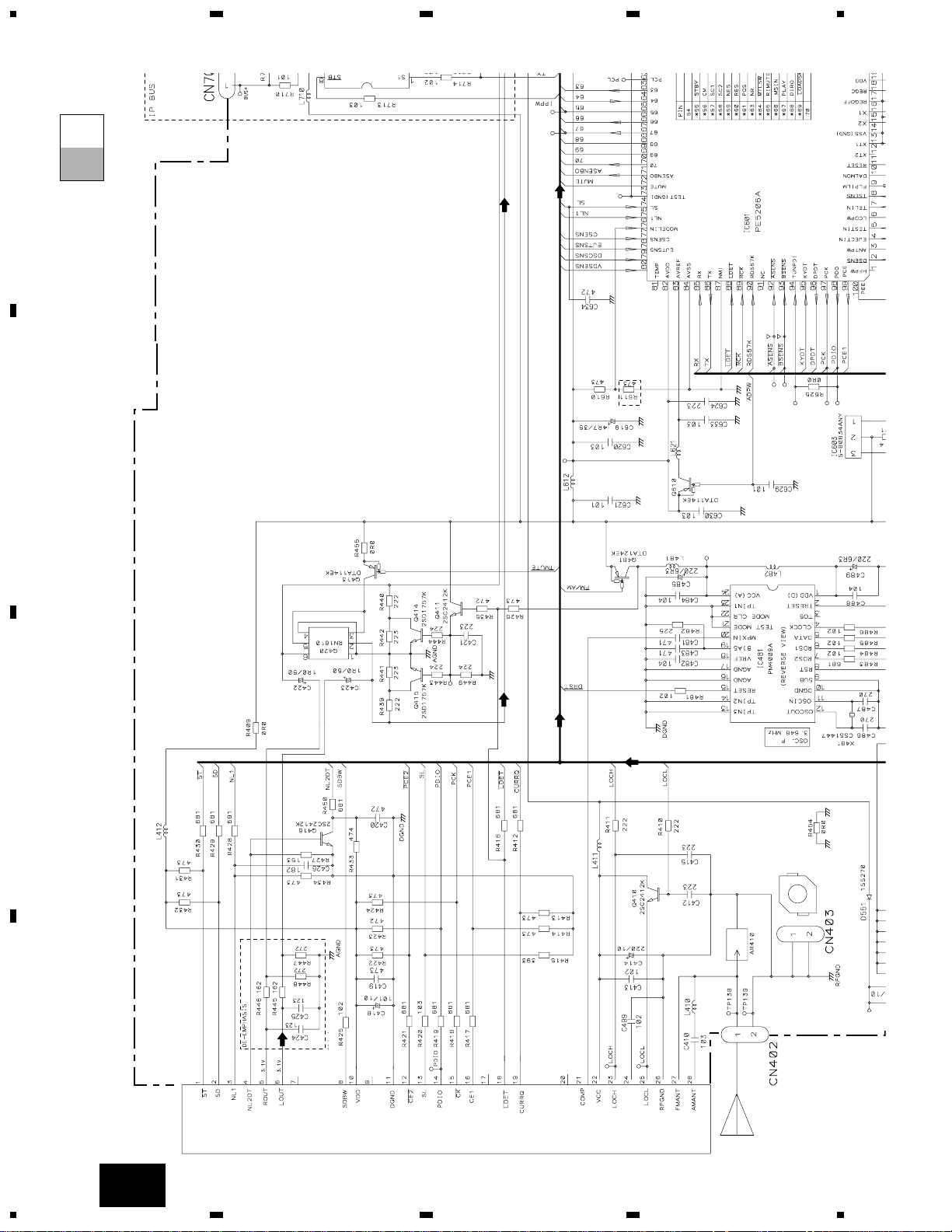
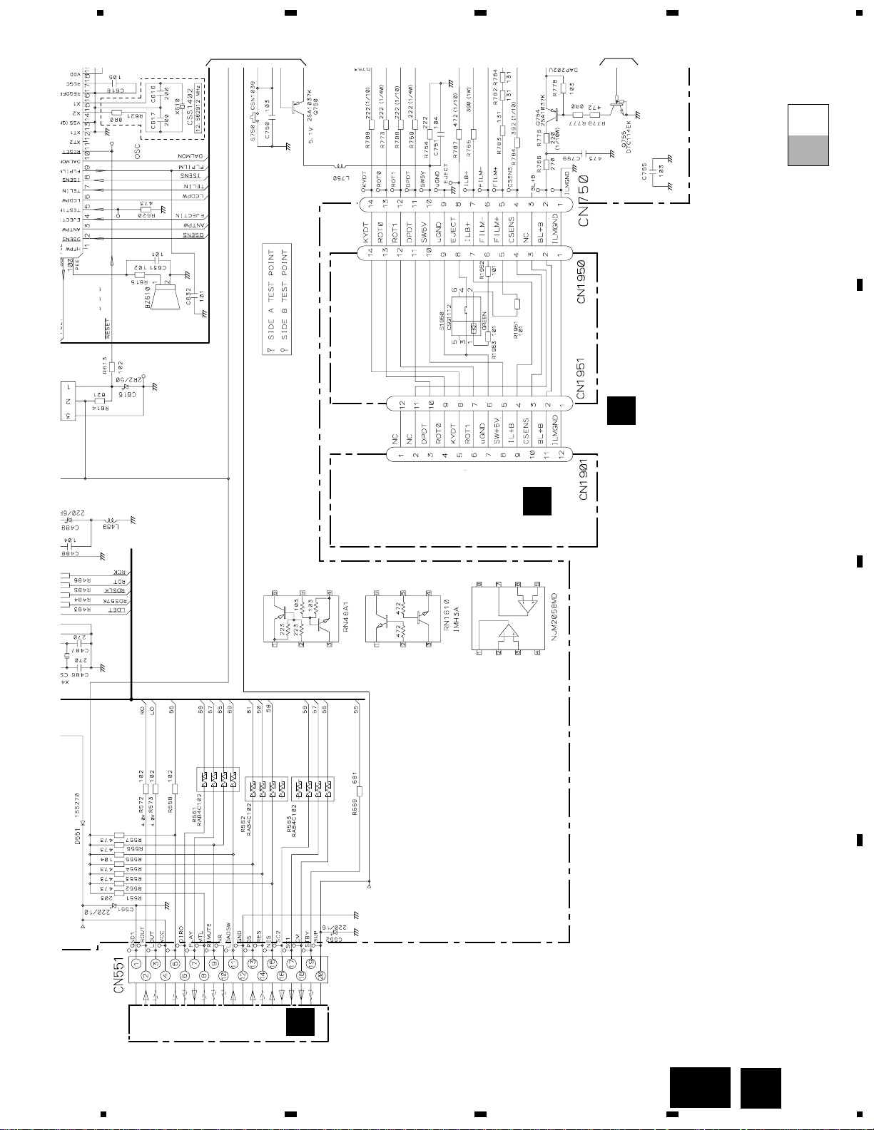
3. BLOCK DIAGRAM AND SCHEMATIC DIAGRAM
3.1 BLOCK DIAGRAM
Q420
Q415
Q413
Q416
Q710
Q711
Q411
Q481
IC 481
PM4009A
IC 710
HA12187FP
X481
RDS
DECODER
IP-BUS DRIVER
1211
20
8
37
MUTE
X1
X2
ILB+
EJECT
CSENS
SW5V
DPDT
KYDT
ROT1
ROT0
BL+B
loadsw
MSIN
PEE
69
100
stby
55
65
RIMUTE
LCDPW
6
EJECTIN
4
DPDT
96
KYDT
95
ROT0
29
ROT1
25
23
20
SYSTEM
CONTROLLER
IC 601(2/2)
PE5206A
BUS–
B.U
BUS+
BUS+L
5
8
1
7
1
2
8
6
5
TX
RX
IPPW
SWVDD
77
CSENS
ILMPW
B.U
VDD
7
10
11
14
12
13
2
8
5
FILM–
6
4
CN750
CN551
CN701
Q751
B.U
Q754
Q755
Q753
Q750
Q752
A
TUNER AMP UNIT
FM/AM TUNER UNIT
BZ610
ALARM
BUZZER
16
X610
15
19
3
FLPILM
9
FILM+
72
mute
S750
PDIO
CURRQ
Q410
LOCL
VCC
LOCH
VDD
B.U
stby
B.U
MUTE
LOAD
5
1
4
2
1
3
11
9
20
19
D
DECK UNIT
IC251
HA12229F
IC351
PA2020A
EQ AMP
MECHANISM
DRIVER
CN251
CN252
CN254
CN255
CN253
6
16
MS
Lch
20
FWD
L-ch
REV
L-ch
39
32
33
18
19
17
3
15 6
8
7
10
CN256
3
15 6
S1
LOAD
S2
MODE
EGN1
REEL
SENSE
M
M
M2
SUB
MOTOR
M1
MAIN
MOTOR
5
2
1
E
REEL SENSE PCB
11
6
55
6
17
f/R
DIRO
68
66
DIRO
MS
9
MCMUTE
stby
loadsw
15
13
15
13
59
61
POS
NES
13
11
POS
NES
POS
ES
18
17
18
17
56
57
16
15
SC1
CM
20
B.U
16
16
58
14
SC2
SC1
CM
SC2
SC1
CM
SC2
VDD
CN402
6
21
18
22 19 12 15 16 8
13 3
2
4
ANT
28
27
IC 3
EEPROM
FM/AM 1ST IF 10.7MHz
T51 Q51 CF51
CF52 CF53
IC1
MIXER, IF AMP, DET.
LDET
COMP
CF202
VCC
DI/DO
CE2
CK
CE1
SDBW
SL
FMSD
NL1
NL2
IC 2 FM MPX
AMANT
FMANT
ATT
ATT
AMRF
FMRF
IMG ADJ
RF ADJ
X901
10.25MHz
ANT ADJ
LOCL
LOCH
AMDET
MPXREF 41kHz
AM 2ND IF
450kHz
CREQ
STIND
L ch
1
14
25
23
5
R ch
7
17
20
24
26
WC
NC
NC
FMLOCL
RFGND
11
DGND
10
VDD
9
NC
mute
Q
VCC
SYSPW
21
SYSPW
DETACH
SENSE SW
VDD
9
11
KEH-P6020RB,P6020R
5
6
78
5
6
7
8
D
C
B
A
C
88
ldet
42
fM/AM
48
11
1
tmute
adpw
bsens
asens
NL2DT
VDD
B.U
B.U
B.U
NL1
7
8
92
93
83
10
22
SD
SL
SDBW
PCE
PCK
pce@
PDO
ASENBO
10
Fout L
11
Rout L
IL+B
µGND
CSENS
SW5V
DPDT
KYDT
RDT1
RDT0
BL+B
ILB+
EJECT
SW5V
DPDT
KYDT
ROT1
ROT0
BL+B
3
10
12
9
11
RL–
5RL+
23 FL–
21 FL+
RL–
RL+
FL–
FL+
5
B.REM
Lch
TEL
6
ILM
4
ACC
1
GND
2
BACK UP
BACK UP
GND
TELIN
isens
AVREF
DALMON
47
75
38
74
TUN L
41
BUS+L
44
CD L
42
49
99
97
32
98
71
86 85 24
FLIN
14
RLIN
12
22 4 25
SYSTEM
CONTROLLER
RESET
POWER AMP
IC 301
PML008A
IC 603
S-80834ANY
IC 361
PAL007A
IC 1902
RS-140
reset
VDD
Q610
Q913
Q914
Q916
Q359
Q351
SYSPW
Q1905
Q917
TX
RX
IPPW
ELECTRONIC VOLUME/
SOURCE SELECTOR
B.REMSTBYMUTE
REMOTE CONTROL
SENSOR
IC 1903
PD6294A
LCD DRIVER
KEY MATRIX
LCD
OPT IN
1
9
8
7
10
3
5
6
4
11
7
10
11
14
12
13
2
7
8
4
8
55
FILM–
66
4
10
11
14
12
13
2
4
3
6
5
10
8
7
9
2
4
DPDT
KYDT
X0
X1
DIMMER
KEY DATA
LCD DATA
REMIN
VDD
9
8
3
X1901
2
7
23 10
N750
CN1951
CN1901
CN1950
S1950
KEYBOARD UNIT
B
PANEL UNIT
REAR/SW
CN351
ACC
RL–
RL+
ILM
MUTE
FL–
FL+
B.REM
RR–
FR–
FL–
RL–
RR+
FR+
FL+
RL+
BACK UP
ILL
GND
B.REM
ACC
2
CN901
FILM+
S1922
IC 601(1/2)
PE5206A
5
1
Q909
6
Q915
7
20
MUTE
st
39
46
currq
50
51
LOCL
LOCH
VDD
VDD
CELLULAR MUTE
7
5
8
6
12
11
13
15
16
10
B.U
SYSPW
Q361
Q910
Q911
mute
Q362
Q912
Q918
VCC
VCC
EJECT
SW
99
VOLUME
3.2 OVERALL CONNECTION DIAGRAM(GUIDE PAGE)
Note: When ordering service parts, be sure to refer to “EXPLODED VIEWS AND PARTS LIST” or “ELECTRICAL PARTS
LIST”.
12
KEH-P6020RB,P6020R
1
23
4
1
234
D
C
B
A
A-a A-b
A-aA-a
A-b A-b
A-b A-b
A-a A-a
Large size
SCH diagram
Guide page
Detailed page
A
A-a
B
DSP-201M-S00B
KEH-P6020RB
FM(100%):-19.5dBs
AM(30%) :-30dBs
B
C
PANEL UNIT
KEYBOARD UNIT
EJECT
FM/AM TUNER UNIT
D
DECK UNIT
13
KEH-P6020RB,P6020R
5
6
78
5
6
7
8
D
C
B
A
A-b
A
DETACH SENSE SW
FUNCTION I/O
IP-BUS:+2.2dBs
FM(100%):+29.6dBs
AM(30%):+19.1dBs
CD:+36.2dBs
IP-BUS:+36.3dBs
FM(100%): +3.6dBs
AM(30%): -6.9dBs
CD:+10.2dBs
IP-BUS:+10.3dBs
FM(100%):-19.5dBs
AM(30%): -30dBs
CD: +4.1dBs
IP-BUS: +2.2dBs
CD:+9.4dBs
SYSTEM CONTROLLER
CEK1136
10A
FUSE
>
600µH
A
TUNER AMP UNIT
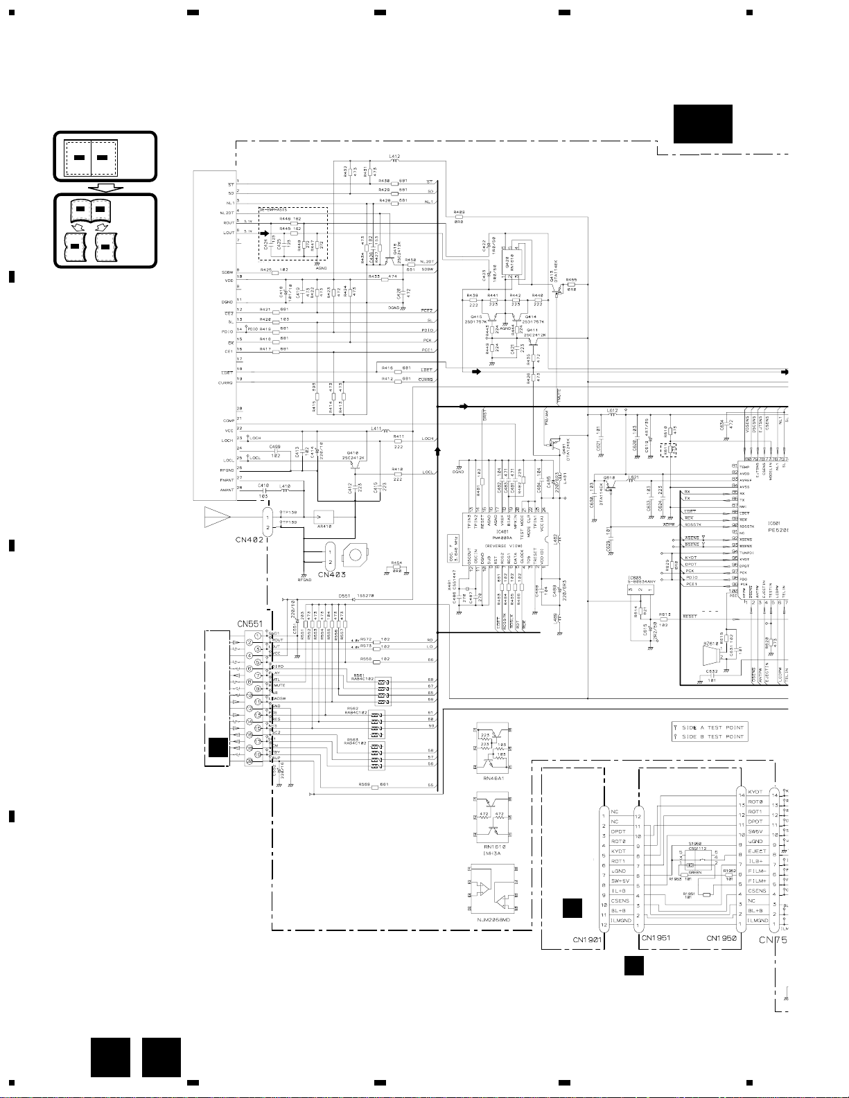
For resistors and capacitors in the circuit diagrams, their resistance values or
capacitance values are expressed in codes:
Ex. *Resistors
Code Practical value
123 12k ohms
103 10k ohms
*Capacitors
Code Practical value
103 0.01uF
101/10 100uF/10V
The > mark found on some component parts indicates
the importance of the safety factor of the part.
Therefore, when replacing, be sure to use parts of
identical designation.
RR–
FR–
FL–
RL–
RR+
FR+
FL+
RL+
BACK UP
ILL
GND
B.REM
ACC
14
KEH-P6020RB,P6020R
1
23
4
1
234
D
C
B
A
DSP-201M-S00B
KEH-P6020RB
FUNCTION
FM(100%):-19.5dBs
AM(30%) :-30dBs
SYSTEM CONTRO
FM/AM TUNER UNIT
A-a
A-a
A-b
15
KEH-P6020RB,P6020R
5
6
78
5
6
7
8
D
C
B
A
A-a
A-a
A-b
DETACH S
B
C
PANEL UNIT
KEYBOARD UNIT
EJECT
D
DECK UNIT
B
1
2

16
1
23
4
1
234
D
C
B
A
A-a
A-b
A-b
KEH-P6020RB,P6020R
FUNCTION I/O
IP-BUS:+2.2dBs
FM(100%): +3.6dBs
AM(30%): -6.9dBs
CD:+10.2dBs
IP-BUS:+10.3dBs
FM(100%):-19.5dBs
AM(30%): -30dBs
CD: +4.1dBs
IP-BUS: +2.2dBs
CD:+9.4dBs
600µH
A
TUNER AMP UNIT
 Loading...