


Service KEH-P780/X1N/UC |
|
Manual |
ORDER NO. |
|
|
|
CRT2306 |
MULTI-CD CONTROL HIGH POWER CASSETTE PLAYER WITH FM/AM TUNER
KEH-P780 X1N/UC
KEH-P7800 X1N/UC
NOTE:
-See the separate manual CX-631(CRT1640) for the cassette mechanism description.
-The cassette mechanism assy employed in this model is one of 2L series.
-Dolby noise reduction manufactured under license from Dolby Laboratories Licensing Corporation. "Dolby" and the double-D symbol are trademarks of Dolby Laboratories Licensing Corporation.
CONTENTS
1. |
SAFETY INFORMATION ........................................... |
2 |
7. |
GENERAL INFORMATION ...................................... |
42 |
2. |
EXPLODED VIEWS AND PARTS LIST...................... |
2 |
|
7.1 PARTS................................................................. |
42 |
3. |
SCHEMATIC DIAGRAM .......................................... |
10 |
|
7.1.1 IC ............................................................... |
42 |
4. |
PCB CONNECTION DIAGRAM ............................... |
20 |
|
7.1.2 DISPLAY ................................................... |
47 |
5. |
ELECTRICAL PARTS LIST ....................................... |
30 |
|
7.2 DIAGNOSIS........................................................ |
48 |
6. |
ADJUSTMENT ........................................................ |
40 |
|
7.2.1 DISASSEMBLY ......................................... |
48 |
|
|
|
|
7.2.2 TEST MODE ............................................. |
49 |
|
|
|
|
7.3 BLOCK DIAGRAM.............................................. |
52 |
|
|
|
8. |
OPERATIONS AND SPECIFICATIONS ................... |
53 |
PIONEER ELECTRONIC CORPORATION |
4-1, Meguro 1-Chome, Meguro-ku, Tokyo 153-8654, Japan |
PIONEER ELECTRONICS SERVICE INC. P.O.Box 1760, Long Beach, CA 90801-1760 U.S.A. |
|
PIONEER ELECTRONIC [EUROPE] N.V. Haven 1087 Keetberglaan 1, 9120 Melsele, Belgium
PIONEER ELECTRONICS ASIACENTRE PTE.LTD. 253 Alexandra Road, #04-01, Singapore 159936
C PIONEER ELECTRONIC CORPORATION 1998
K-ZZS. NOV. 1998 Printed in Japan

KEH-P780,P7800
1. SAFETY INFORMATION
CAUTION
This service manual is intended for qualified service technicians; it is not meant for the casual do-it-yourselfer. Qualified technicians have the necessary test equipment and tools, and have been trained to properly and safely repair complex products such as those covered by this manual.
Improperly performed repairs can adversely affect the safety and reliability of the product and may void the warranty. If you are not qualified to perform the repair of this product properly and safely; you should not risk trying to do so and refer the repair to a qualified service technician.
WARNING
This product contains lead in solder and certain electrical parts contain chemicals which are known to the state of California to cause cancer, birth defects or other reproductive harm.
Health & Safety Code Section 25249.6 - Proposition 65
2. EXPLODED VIEWS AND PARTS LIST
2.1 PACKING
2 |
7 |
4 |
|
8
 5
5
6
10 18
3
 11
11
13
19
1
12 


 21
21
20
17
14
2
KEH-P780,P7800
NOTE:
-Parts marked by “*” are generally unavailable because they are not in our Master Spare Parts List.
-Screws adjacent to mark on the product are used for disassembly.
(1)PACKING SECTION PARTS LIST
Mark No. Description |
Part No. |
Mark No. Description |
Part No. |
||||
|
|
|
|
|
|
|
|
|
1 |
Cord Assy |
See Contrast table(2) |
16 |
Protector |
CHP2101 |
|
* |
2 |
Accessory Assy |
CEA2350 |
17 |
Protector |
CHP2102 |
|
|
3 |
Spring |
CBH1650 |
18 |
Remote Control Unit |
See Contrast table(2) |
|
|
4 |
Screw Assy |
CEA2351 |
19 |
Case Assy |
CXB3520 |
|
|
5 |
Screw |
CBA1304 |
20-1 |
Owner’s Manual |
See Contrast table(2) |
|
|
|
|
|
|
|
(English, French) |
|
* |
6 |
Polyethylene Bag |
CEG-127 |
|
|
|
|
|
7 |
Screw |
CRZ50P090FMC |
20-2 |
Installation Manual |
See Contrast table(2) |
|
|
8 |
Screw |
TRZ50P080FMC |
|
|
(English, French) |
|
* |
9 |
Polyethylene Bag |
CEG-158 |
* 20-3 |
Warranty Card |
See Contrast table(2) |
|
|
10 |
Handle |
CNC5395 |
21 |
Cord Assy |
See Contrast table(2) |
|
|
11 |
Bush |
CNV3930 |
|
|
|
|
|
12 |
Polyethylene Bag |
CEG1173 |
|
|
|
|
|
13 |
Battery |
See Contrast table(2) |
|
|
|
|
|
14 |
Carton |
See Contrast table(2) |
|
|
|
|
|
15 |
Contain Box |
See Contrast table(2) |
|
|
|
|
(2) CONTRAST TABLE
KEH-P780/X1N/UC and KEH-P7800/X1N/UC are constructed the same except for the following:
Mark No. Symbol and Description |
Part No. |
||
KEH-P780/X1N/UC |
KEH-P7800/X1N/UC |
||
1 |
Cord Assy |
CDE5758 |
Not used |
13 |
Battery |
CEX1030 |
Not used |
14 |
Carton |
CHG3551 |
CHG3550 |
15 |
Contain Box |
CHL3551 |
CHL3550 |
18 |
Remote Control Unit |
CXB3456 |
Not used |
20-1 |
Owner’s Manual |
CRD2760 |
CRD2758 |
20-2 |
Installation Manual |
CRD2761 |
CRD2759 |
* 20-3 |
Warranty Card |
CRY1070 |
Not used |
21 |
Cord Assy |
Not used |
CDE5802 |
3
KEH-P780,P7800
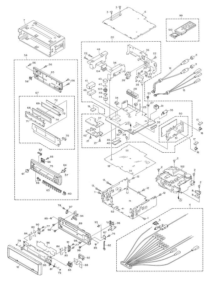
2.2 EXTERIOR
4
KEH-P780,P7800
(1) EXTERIOR SECTION PARTS LIST
Mark No. |
Description |
Part No. |
Mark No. Description |
Part No. |
||
1 |
Screw |
BMZ30P040FMC |
|
41 |
Case |
CNC8254 |
2 |
Screw |
BSZ26P050FMC |
42 |
Holder |
CNC8255 |
|
3 |
Screw |
BSZ30P050FMC |
43 |
Case |
CNC8350 |
|
4 |
Cord Assy |
See Contrast table(2) |
44 |
Case |
CNC8351 |
|
5 |
Fuse(10A) |
CEK1136 |
45 |
Insulator |
CNM6099 |
|
6 |
Case |
CNB2350 |
46 |
Insulator |
CNM6190 |
|
7 |
Holder |
CNC6798 |
47 |
Insulator |
CNM6257 |
|
8 |
Shield |
CNC7365 |
48 |
Heat Sink |
CNR1505 |
|
9 |
Spacer |
CNM5488 |
49 |
Insulator |
CNV5792 |
|
10 |
Panel |
CNS5148 |
50 |
FM/AM Tuner Unit |
CWE1467 |
|
11 |
Cap |
CNV2680 |
51 |
Holder |
CNC6554 |
|
12 |
Screw |
BSZ30P050FMC |
52 |
Chassis Unit |
CXB3048 |
|
13 |
Screw |
BSZ30P200FMC |
53 |
Screw |
ISS26P055FUC |
|
14 |
Cord |
CDE5176 |
54 |
Detach Grille Assy |
See Contrast table(2) |
|
15 |
Cord |
See Contrast table(2) |
55 |
Screw |
BPZ20P060FMC |
|
16 |
Holder |
CNC5704 |
56 |
Screw |
BPZ20P080FZK |
|
17 |
Cushion |
CNM4870 |
57 |
Button(OPEN) |
CAC5804 |
|
18 |
Insulator |
CNM6275 |
58 |
Button(EJECT) |
CAC5805 |
|
19 |
Insulator |
CNV5793 |
59 |
Button(SOURCE) |
CAC5806 |
|
20 |
Tuner Amp Unit |
See Contrast table(2) |
60 |
Button(BAND) |
CAC5807 |
|
21 |
Screw |
BMZ26P040FMC |
61 |
Button(EQ) |
CAC5808 |
|
22 |
Screw |
BPZ26P060FMC |
62 |
Button(DISP) |
CAC5809 |
|
23 |
Screw |
BSZ26P060FMC |
63 |
Button(1-6) |
CAC5922 |
|
24 |
Screw |
BSZ26P160FMC |
64 |
Spring |
CBH2205 |
|
25 |
Clamper |
See Contrast table(2) |
65 |
Cover |
CNS5146 |
|
26 |
Pin Jack(CN301) |
CKB1028 |
66 |
Holder |
CNV5537 |
|
27 |
Terminal(CN403) |
CKF1059 |
67 |
Keyboard Unit |
CWM6061 |
|
28 |
Plug(CN951) |
CKM1231 |
68 |
LCD(LCD901) |
CAW1502 |
|
29 |
Plug(CN604) |
CKS-783 |
69 |
EL |
CEL1587 |
|
30 |
Connector(CN601) |
CKS1499 |
70 |
Connector(CN901) |
CKS2733 |
|
31 |
Connector(CN751) |
CKS3408 |
71 |
Holder |
CNC7992 |
|
32 |
Connector(CN602) |
CKS3568 |
72 |
Tape |
CNM6348 |
|
33 |
Connector(CN603) |
See Contrast table(2) |
73 |
Spacer |
CNM6347 |
|
34 |
Connector(CN302) |
CKS3598 |
74 |
Connector |
CNV5536 |
|
35 |
Antenna Jack(CN402) |
CKX1056 |
75 |
Grille Unit |
See Contrast table(2) |
|
36 |
Panel |
See Contrast table(2) |
76 |
Screw |
BPZ20P060FMC |
|
37 |
Heat Sink |
CNC7991 |
77 |
Screw |
CBA1082 |
|
38 |
Holder |
CNC7996 |
78 |
Screw |
CBA1176 |
|
39 |
Holder |
CNC7997 |
79 |
Washer |
CBF1001 |
|
40 |
Case |
CNC7998 |
80 |
Spring |
CBH2063 |
|
5
KEH-P780,P7800
Mark No. |
Description |
Part No. |
|
Mark No. Description |
Part No. |
|
81 |
Spring |
CBH2204 |
96 |
Holder Unit |
CXB3051 |
|
82 |
Cord |
CDE5800 |
97 |
Damper Unit |
CXB3180 |
|
83 |
Connector |
CKS2780 |
98 |
Screw |
IMS20P040FZK |
|
84 |
Roller |
CLA3386 |
99 |
Remote Control Unit |
See Contrast table(2) |
|
85 |
Cushion |
CNM5486 |
100 |
Cover |
See Contrast table(2) |
|
86 |
Sheet |
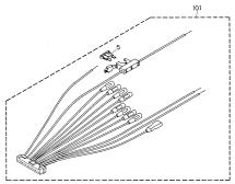
CNM6109 |
101 |
Cord Assy |
See Contrast table(2) |
|
87 |
PCB |
CNP5430 |
102 |
Cassette Mechanism Module |
EXK3990 |
|
88 |
PCB |
CNP5444 |
103 |
Coil(L801) |
CTH1227 |
|
89 |
Panel |
CNS5147 |
104 |
IC(IC301) |
PAL005A |
|
90 |
Holder |
CNS5157 |
105 |
Transistor(Q951) |
2SD2396 |
|
91 |
Holder |
CNS5165 |
|
|
|
|
92 |
Holder |
CNS5389 |
|
|
|
|
93 |
Switch(S602) |
CSN1027 |
|
|
|
|
94 |
Holder Unit |
CXB3049 |
|
|
|
|
95 |
Holder Unit |
CXB3050 |
|
|
|
|
(2) CONTRAST TABLE
KEH-P780/X1N/UC and KEH-P7800/X1N/UC are constructed the same except for the following:
Mark No. Description |
Part No. |
||
KEH-P780/X1N/UC |
KEH-P7800/X1N/UC |
||
4 |
Cord Assy |
CDE5758 |
Not used |
15 |
Cord |
CDE5762 |
Not used |
20 |
Tuner Amp Unit |
CWM6143 |
CWM6145 |
25 |
Clamper |
CEF1005 |
Not used |
33 |
Connector(CN603) |
CKS3597 |
Not used |
36 |
Panel |
CNB2357 |
CNB2358 |
54 |
Detach Grille Assy |
CXB3437 |
CXB3438 |
75 |
Grille Unit |
CXB3481 |
CXB3482 |
99 |
Remote Control Unit |
CXB3456 |
Not used |
100 |
Cover |
CNS4948 |
Not used |
101 |
Cord Assy |
Not used |
CDE5802 |
6
KEH-P780,P7800
7
KEH-P780,P7800
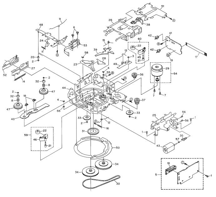
2.3 CASSETTE MECHANISM MODULE
8
KEH-P780,P7800
- CASSETTE MECHANISM MODULE SECTION PARTS LIST
Mark No. Description |
Part No. |
|
Mark No. Description |
Part No. |
||
1 |
Screw |
BSZ20P040FMC |
31 |
Gear |
ENV1347 |
|
2 |
Washer |
CBF1037 |
32 |
Collar |
ENV1508 |
|
3 |
Washer |
CBF1038 |
33 |
Gear |
ENV1350 |
|
4 |
Washer |
CBG1003 |
34 |
Flywheel |
ENV1500 |
|
5 |
Deck Unit |
EWM1018 |
35 |
Worm Gear |
ENV1439 |
|
6 |
Screw |
EBA1028 |
36 |
Worm Wheel |
ENV1440 |
|
7 |
Screw |
EBA1037 |
37 |
Gear |
ENR1037 |
|
8 |
Spring |
EBH1531 |
38 |
Lever |
ENV1442 |
|
9 |
Spring |
EBH1575 |
39 |
Arm |
ENV1525 |
|
10 |
Plug(CN251) |
CKS3540 |
40 |
Gathering PCB |
ENX1037 |
|
11 |
Spring |
EBH1515 |
41 |
Gathering PCB |
ENX1042 |
|
12 |
Spring |
EBH1587 |
42 |
Switch(S1,S2) |
ESG1004 |
|
13 |
Spring |
EBH1517 |
43 |
Motor Unit(M2) |
EXA1485 |
|
14 |
Spring |
EBH1518 |
44 |
Chassis Unit |
EXA1567 |
|
15 |
Spring |
EBH1519 |
45 |
Pinch Holder |
ENV1485 |
|
16 |
Spring |
EBH1537 |
46 |
Pinch Holder |
ENV1486 |
|
17 |
Cord |
EDD1020 |
47 |
Reel Unit |
EXA1543 |
|
18 |
Photo-interrupter(EGN2,3) |
EGN1006 |
48 |
Head Base Unit |
EXA1457 |
|
19 |
Photo-interrupter(EGN1) |
EGN1005 |
49 |
Lever Unit |
EXA1438 |
|
20 |
Roller |
ENR1031 |
50 |
Gear Unit |
EXA1545 |
|
21 |
Shaft |
ELA1373 |
51 |
Frame Unit |
EXA1458 |
|
22 |
Pinch Roller |
ENV1518 |
52 |
Lever Unit |
EXA1439 |
|
23 |
Arm |
ENC1489 |
53 |
Head Assy(HD1) |
EXA1506 |
|
24 |
Arm |
ENC1397 |
54 |
Motor Unit(M1) |
EXA1490 |
|
25 |
Guide |
ENC1481 |
55 |
Washer |
HBF-179 |
|
26 |
Holder |
ENC1417 |
56 |
Screw |
BMZ20P022FMC |
|
27 |
Lever |
ENC1448 |
57 |
Spring |
EBH1545 |
|
28 |
Arm |
ENC1488 |
58 |
Washer |
YE20FUC |
|
* 29 |
Motor |
EXM1031 |
59 |
Pinch Holder Unit |
EXA1529 |
|
30 |
Belt |
ENT1027 |
60 |
Pinch Holder Unit |
EXA1528 |
|
9

1 |
|
2 |
|
3 |
|
4 |
|
|
|
KEH-P780,P7800
3. SCHEMATIC DIAGRAM
3.1 OVERALL CONNECTION DIAGRAM (GUIDE PAGE)
Note: When ordering service parts, be sure to refer to “EXPLODED VIEWS AND PARTS LIST” or “ELECTRICAL
PARTS LIST”. |
|
A-a |
|
A |
|
|
|
|
|
|
|
|
|
|
B |
|
|
Large size |
ANTENNA JACK |
A-a |
A-b |
SCH diagram |
|
|
|
||
A-a |
A-b |
Guide page |
|
B |
|
|
|
A-a |
A-b |
Detailed page |
|
C
D E F MODULE
D
C 
10 A C
1 |
2 |
3 |
4 |
5 |
|
6 |
|
7 |
|
8 |
|
|
|
KEH-P780,P7800
A-b
A
A 
B
C
D
A 11
5 |
|
6 |
|
7 |
|
8 |
|
|
|
||||
|
|
|
1 |
2 |
3 |
4 |
KEH-P780,P7800
A
B
C
D
A-a A-b
ANTENNA JACK
B
12 A-a
1 |
2 |
3 |
4 |

5 |
6 |
7 |
8 |
KEH-P780,P7800
A-a A-b
A
B
C
MODULE |
DEF |
C
A-a C 13
D
5 |
|
6 |
|
7 |
|
8 |
|
|
|
||||
|
|
|

1 |
|
2 |
|
3 |
|
4 |
|
|
|
KEH-P780,P7800
A-a A-b
A
B
C
D
14
A
A-b
1 |
2 |
3 |
4 |

5 |
|
6 |
|
7 |
|
8 |
|
|
|
KEH-P780,P7800
A-a A-b
A
B
C
D
A-b 15
5 |
6 |
7 |
8 |
1 |
|
2 |
|
3 |
|
4 |
|
|
|
KEH-P780,P7800
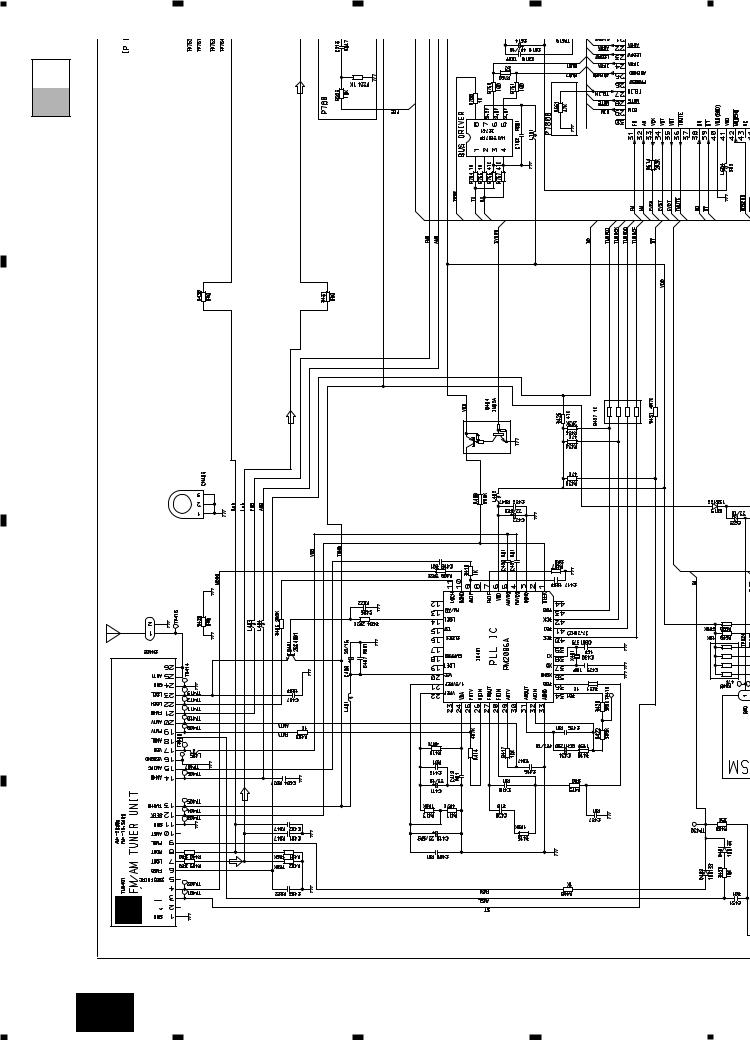
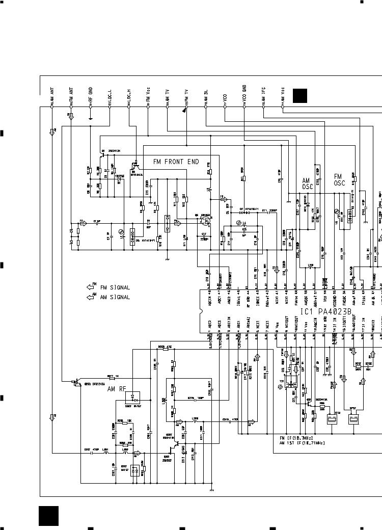
3.2 FM/AM TUNER UNIT
A
B FM/AM TUNER U
B
|
|
|
MA157 |
D1 RD39JS |
R1 |
2R2M |
D6 |
D2 RD39JS |
R2 |
2R2M |
|
C
1
2
3
D
16 B
1 |
2 |
3 |
4 |

R UNIT
5 |
|
6 |
|
7 |
|
8 |
|
|
|
KEH-P780,P7800
A |
A |
|
IFC |
B
C
D
B 17
5 |
|
6 |
|
7 |
|
8 |
|
|
|
||||
|
|
|

1 |
|
2 |
|
3 |
|
4 |
|
|
|
KEH-P780,P7800
3.3 CASSETTE MECHANISM MODULE
A
|
RL |
Rev |
|
RR |
Rev |
|
FR |
Fwd |
B |
FL |
Fwd |
|
|
|
|
HD1 |
|
|
HEAD ASSY |
|
|
EXA1506 |
|
|
TEST TAPE |
|
|
NCT-150 |
|
|
(400Hz, 200nWb/m) |
|
C
D
|
D DECK UNIT |
|
|
|
|
|
|
|
|
|
|
|
|
|
|
|
|
|
||
|
|
|
|
|
|
|
|
|
VR302 |
|
|
|
|
|
|
|
|
|
|
|
|
|
|
|
|
|
|
|
CCP1280 |
|
|
|
|
|
|
|
|
|
|
||
|
|
|
|
|
|
|
|
|
33K(B) |
|
|
|
|
C310R1 |
|
|
|
|
|
|
|
C253 |
330P |
|
|
R01 |
1K |
|
|
C302 |
R1 |
|
R301 |
18K |
|
|
|
|
|
|
|
|
|
|
|
|
C256 |
R258 |
|
|
|
|
|
|
|
|
|
|
|
|
|
|
|
|
|
|
|
|
|
30 |
29 |
28 |
27 |
26 |
25 |
24 |
23 |
22 |
21 |
|
|
|
|
R283 |
0R0 |
|
|
|
|
|
|
|
|
|
|
|
|
|
|
|
|
|
|
|
|
|
|
|
|
|
C302 |
R1 |
|
|
|
|
|
|
|
|
20 |
|
|
|
|
|
C254 |
330P |
R256 |
220 |
|
31 |
|
|
|
|
|
|
|
|
|
R273 |
1K |
|
|
|
R284 |
0R0 |
|
|
|
|
32 |
|
|
|
|
|
|
|
|
|
19 |
R272 |
1K |
|
|
|
|
|
|
|
|
33 |
|
|
|
|
|
|
|
|
|
18 |
R271 |
1K |
R290 |
0R |
R282 |
0R0 |
330P |
C273 |
R287 |
34 |
|
CXA2560Q |
|
17 |
R274 |
1K |
|
|
|||||||
|
C252 |
35 |
|
|
16 |
|
|
|
|
|||||||||||
|
|
|
22/16 |
0R0 |
36 |
|
|
|
|
|
|
|
|
|
15 |
|
|
C403 |
R |
|
|
|
R281 |
0R0 |
|
|
37 |
|
|
|
|
|
|
|
|
|
14 |
|
|
||
|
|
|
|
|
|
|
|
|
|
|
|
|
|
|
|
|
||||
|
C251 |
330P |
|
|
|
38 |
|
|
|
|
|
|
|
|
|
13 |
|
|
R403 |
8 |
|
|
|
|
|
|
|
|
|
|
|
|
|
|
|
C402 |
|
||||
|
|
|
|
|
|
39 |
|
|
|
|
|
|
|
|
|
12 |
|
|
R40 |
|
|
|
|
|
|
|
|
|
|
|
|
|
|
|
|
|
|
|
|||
|
|
|
R255 |
220 |
|
40 |
|
|
|
|
|
|
|
|
|
11 |
|
|
4700P |
|
|
|
|
|
|
|
|
|
|
|
|
|
|
|
|
|
|
|
|
C401 |
R40 |
|
|
|
|
|
|
|
|
|
|
|
|
|
|
|
|
|
|
|
R33 |
4R7 |
C255 |
1 2 3 4 |
5 6 7 8 9 10 |
|
|
|
||
R257 |
|
|
|
|
|
|
|
R01 |
1K |
|
|
|
|
|
|
|
|
C301 |
R1 |
C309 R1 |
C313 100P |
R323 0R0 |
R322 1K |
|
VR301 |
|
|
|
|
|
|
|
33K(B) |
CCP1280 |
|
|
|
|
|
|
|
C272 |
R1 |
Signal GND |
0R0 |
0R0 |
|
|
R386 |
R285 |
|
|
MUTE |
-6dBs(388mV)±1dB |
A CN602 |
18 D
1 |
2 |
3 |
4 |
 Loading...