

Page 1

CLASS D MONO AMPLIFIER
AMPLIFICATEUR MONO DE CLASSE D
AMPLIFICADOR MONO CLASE D
GM-D8601
GM-D9601
English Français Español
Owner’s Manual
Mode d’emploi
Manual de instrucciones
Page 2
Section
01
Before you start
Thank you for purchasing this PIONEER
product
To ensure proper use, please read through this
manual before using this product. It is especially important that you read and observe
WARNINGs and CAUTIONs in this manual.
Please keep the manual in a safe and accessible
place for future reference.
After-sales service for
Pioneer products
Please contact the dealer or distributor from
where you purchased this unit for after-sales
service (including warranty conditions) or any
other information. In case the necessary information is not available, please contact the
companies listed below:
Please do not ship your unit to the companies
at the addresses listed below for repair without
advance contact.
U.S.A.
Pioneer Electronics (USA) Inc.
CUSTOMER SUPPORT DIVISION
P.O. Box 1760
Long Beach, CA 90801-1760
800-421-1404
CANADA
Pioneer Electronics of Canada, Inc.
CUSTOMER SATISFACTION DEPARTMENT
340 Ferrier Street
Unit 2
Markham, Ontario L3R 2Z5, Canada
1-877-283-5901
905-479-4411
For warranty information please see the Limited Warranty sheet included with this unit.
If you experience problems
Should this product fail to operate properly,
please contact your dealer or nearest authorized Pioneer Service Station.
Visit our website
http://www.pioneerelectronics.com
in Canada
http://www.pioneerelectronics.ca
! Learn about product updates (such as firm-
ware updates) for your product.
! Register your product to receive notices
about product updates and to safeguard
purchase details in our files in the event of
loss or theft.
! Access owner’s manuals, spare parts infor-
mation, service information, and much
more.
The Safety of Your Ears is in
Your Hands
Get the most out of your equipment by playing
it at a safe level—a level that lets the sound
come through clearly without annoying blaring or distortion and, most importantly, without affecting your sensitive hearing. Sound
can be deceiving. Over time, your hearing
“comfort level” adapts to higher volumes of
sound, so what sounds “normal” can actually
be loud and harmful to your hearing. Guard
against this by setting your equipment at a
safe level BEFORE your hearing adapts.
ESTABLISH A SAFE LEVEL:
! Set your volume control at a low setting.
! Slowly increase the sound until you can
hear it comfortably and clearly, without distortion.
! Once you have established a comfortable
sound level, set the dial and leave it there.
2
En
Page 3

Before you start
Section
01
BE SURE TO OBSERVE THE FOLLOWING
GUIDELINES:
! Do not turn up the volume so high that you
can’t hear what’s around you.
! Use caution or temporarily discontinue use
in potentially hazardous situations.
! Do not use headphones while operating a
motorized vehicle; the use of headphones
may create a traffic hazard and is illegal in
many areas.
About This Product
This product is a mono amplifier for subwoofer. If
both L (left) and R (right) channels are connected
to the RCA input of this product, output is mixed
because this product is a mono amplifier.
Before connecting/
installing the amplifier
WARNING
! Handling the cord on this product or cords as-
sociated with accessories sold with the product may expose you to chemicals listed on
proposition 65 known to the State of California
and other governmental entities to cause cancer and birth defect or other reproductive
harm. Wash hands after handling.
! This unit is for vehicles with a 12 V battery and
negative grounding. Before installing in recreational vehicles, trucks or buses, check the
battery voltage.
! When installing this unit, make sure to con-
nect the ground wire first. Ensure that the
ground wire is properly connected to metal
parts of the car’s body. The ground wire of the
one of this unit must be connected to the car
separately with different screws. If the screw
for the ground wire loosens or falls out, it
could result in fire, generation of smoke or
malfunction.
! Be sure to install the fuse to the battery wire.
! Always use a fuse of the rating prescribed.
English
The use of an improper fuse could result in
overheating and smoke, damage to the product and injury, including burns.
! Check the connections of the power supply
and speakers if the fuse of the separately sold
battery wire or the amplifier fuse blows. Determine and resolve the cause, then replace the
fuse with and identical equivalent.
! Always install the amplifier on a flat surface.
Do not install the amplifier on a surface that
is not flat or on a surface with a protrusion.
Doing so could result in malfunction.
! When installing the amplifier, do not allow
parts such as extra screws to get caught between the amplifier and the automobile.
Doing so could cause malfunction.
! Do not allow this unit to come into contact
with liquids. Electrical shock could result.
Also, damage to this unit, smoke, and overheating could result from contact with liquids.
The surfaces of the amplifier and any attached
speakers may also heat up and cause minor
burns.
! In the event of any abnormality, the power
supply to the amplifier is cut off to prevent
equipment malfunction. If this occurs, switch
the system power off and check the power
supply and speaker connections. If you are unable to determine the cause, please contact
your dealer.
! Always disconnect the negative * terminal of
the battery beforehand to avoid the risk of
electric shock or short circuit during installation.
! Do not attempt to disassemble or modify this
unit. Doing so may result in fire, electric
shock or other malfunction.
CAUTION
! Always keep the volume low enough to hear
outside sounds.
! Extended use of the car stereo while the en-
gine is at rest or idling may exhaust the battery.
En
3
Page 4

Section
01
Before you start
! Connect either of three subwoofers to the am-
plifier; 1: a subwoofer with a 300 W (GMD8601) / 500 W (GM-D9601) or larger nominal
input and an impedance 4W, 2: a subwoofer
with a 500 W (GM-D8601) / 800 W (GM-D9601)
or larger nominal input and an impedance 2 W
or 3: a subwoofer with a 800 W (GM-D8601) /
1 200 W (GM-D9601) or larger nominal input
and an impedance 1 W.
If the nominal input and impedance are out of
the above ranges, the subwoofer may catch
fire, emit smoke or become damaged.
About the protection function
This product has protection function. When this
product detects something abnormal, the following functions will operate to protect the product
and speaker output.
! The POWER/PROTECT indicator will turn red
and the amplifier will shut down in the situations outlined below.
— If the temperature inside the amplifier gets
too high.
— If a DC voltage is applied to the speaker
output terminal.
! The POWER/PROTECT indicator will turn red
and the output will be muted in the situations
outlined below.
— If the speaker output terminal and speaker
wire are short-circuited.
Important (Serial number)
The serial number is located on the bottom of
this unit. For your own security and convenience,
be sure to record this number on the enclosed
warranty card.
4
En
Page 5
Setting the unit
Section
02
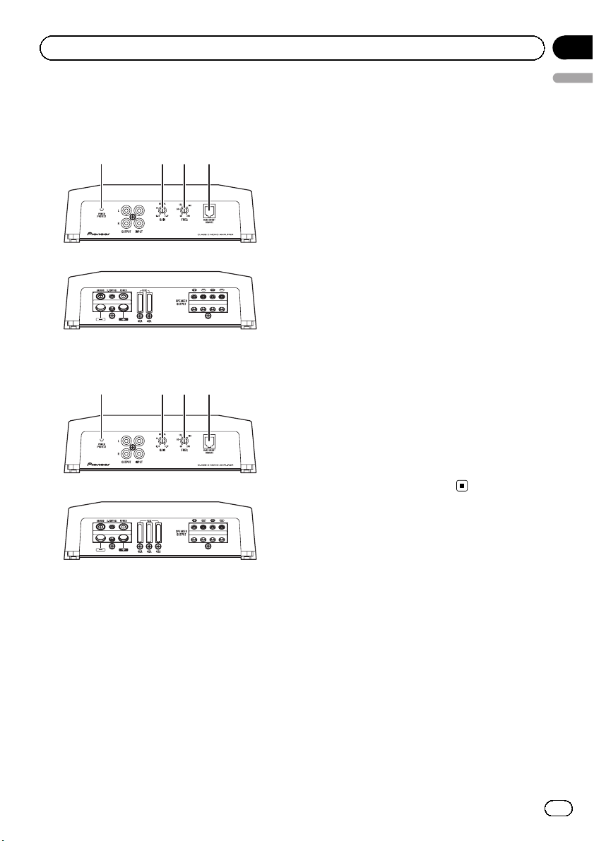
What’s what
GM-D8601
Front side
Rear side
GM-D9601
Front side
Rear side
21 3 4
21 3 4
stereo volume is turned up, turn these con-
English
trols to higher level.
! For use with an RCA equipped car stereo
(standard output of 500 mV), set to the
NORMAL position. For use with an RCA
equipped Pioneer car stereo, with maximum output of 4 V or more, adjust level
to match that of the car stereo output.
! For use with an RCA equipped car stereo
with output of 4 V, set to the H position.
! If you hear too much noise when using
the speaker input terminals, turn the
gain control to higher level.
3 LPF (low-pass filter) cut off frequency
control
You can select a cut off frequency from
40 Hz to 240 Hz.
4 BASS BOOST REMOTE (bass boost level
remote control) jack
By connecting the Bass boost level remote
control to the jack on the main unit, you will
be able to select a bass boost level from
0 dB to 18 dB.
For instruction of connecting the bass boost
remote control to the amplifier, see the Con-
nection diagram on page 7.
To adjust the switch, use a flathead screwdriver if needed.
1 POWER/PROTECT indicator
The power indicator lights up to indicate
power ON.
! If something is not normal, the indicator
turns red.
2 GAIN (gain) control
If output remains low, even when the car
stereo volume is turned up, turn controls to
lower level. If distortion occurs when the car
Setting gain properly
! Protective function included to prevent
malfunction of the unit and/or speakers
due to excessive output, improper use or
improper connection.
! When outputting high volume sound etc.,
this function cuts off the output for a few
seconds as a normal function, but output
is restored when the volume of the head
unit is turned down.
En
5
Page 6
Section
02
Setting the unit
! A cut in sound output may indicate impro-
per setting of the gain control. To ensure
continuous sound output with the head
unit at a high volume, set amplifier gain
control to a level appropriate for the preout
maximum output level of the head unit, so
that volume can remain unchanged and to
control excess output.
! Despite correct volume and gain settings,
the unit sound still cuts out periodically. In
such cases, please contact the nearest
authorized Pioneer Service Station.
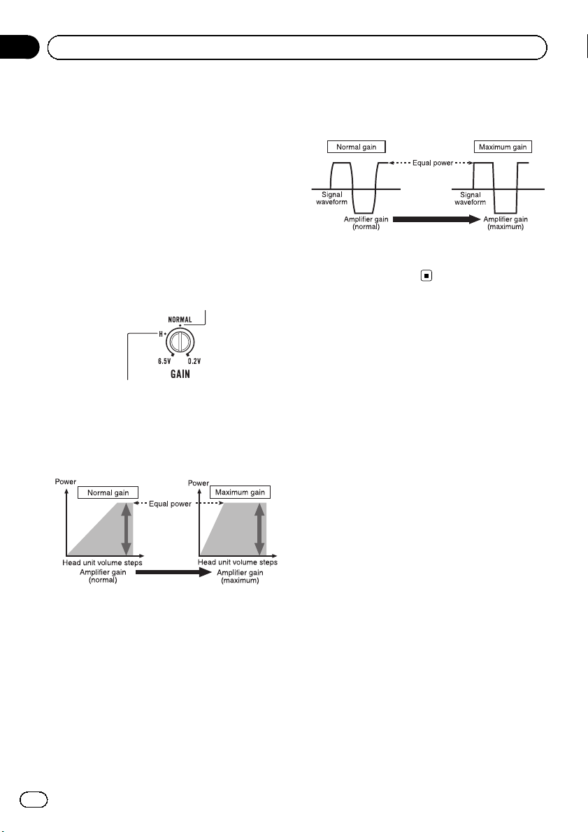
Gain control of this unit
Preout level: 2V (Standard: 500 mV)
Preout level: 4V
Above illustration shows NORMAL gain setting.
Relationship between amplifier gain
and head unit output power
Signal waveform when outputting at
high volume using amplifier gain
control
Signal waveform distorted with high output, if
you raise the gain of the amplifier the power
changes only slightly.
If amplifier gain is raised improperly, this will
simply increase distortion, with little increase
in power.
6
En
Page 7
Connecting the units
Section
03
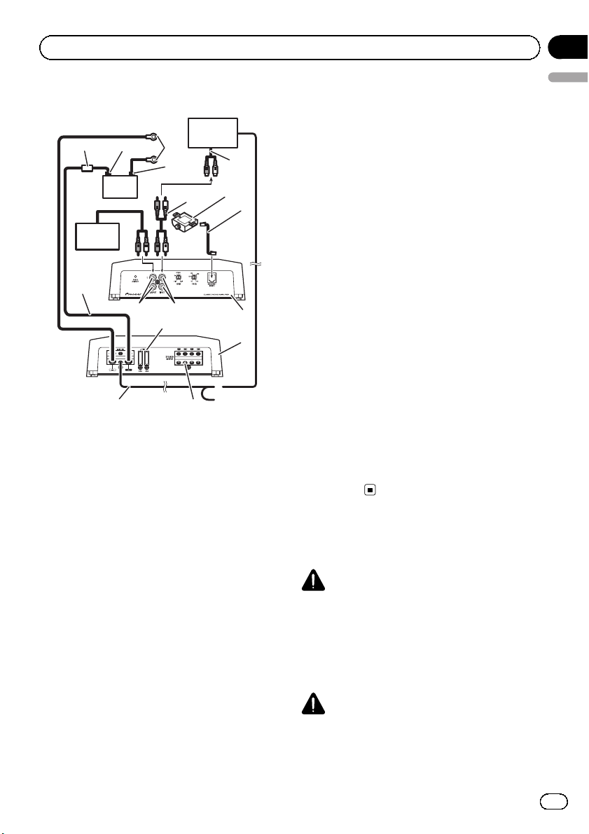
Connection diagram
2
1
1 Battery wire (sold separately)
3
5
a
e
h
f
! The maximum length of the wire be-
tween the fuse and the positive + terminal of the battery is 30 cm (12 in.).
! For the wire size, refer to Connecting the
power terminal on page 9. The batter y
wire, the ground wire and the optional
direct ground wire must be same size.
After making all other connections at
the amplifier, connect the battery wire
terminal of the amplifier to the positive
+ terminal of the battery.
2 Fuse 100 A (GM-D8601) / 150 A (GM-D9601)
(sold separately)
Each amplifier must be separately fused at
100 A (GM-D8601) / 150 A (GM-D9601).
3 Positive (+) terminal
4 Negative (*) terminal
5 Battery (sold separately)
6 Ground wire, Terminal (sold separately)
The ground wires must be same size as the
battery wire.
Connect to metal body or chassis.
7
6
4
9
d
g
8
b
c
i
j
7 Car stereo with RCA output jacks (sold sepa-
English
rately)
8 External output
9 Connecting wire with RCA pin plugs (sold se-
parately)
a Amplifier with RCA input jacks (sold sepa-
rately)
b Bass boost level remote control
c Bass boost level remote control wire (5 m
(16 ft. 5 in.))
d RCA input jack
e RCA output jack
f System remote control wire (sold separately)
Connect male terminal of this wire to the system remote control terminal of the car stereo.
The female terminal can be connected to the
auto-antenna relay control terminal. If the car
stereo lacks a system remote control terminal,
connect the male terminal to the power terminal via the ignition switch.
g Speaker output terminals
Please see the following section for speaker
connection instructions. Refer to Connections
when using the speaker input wire on page 9.
h Fuse 40 A × 2 (GM-D8601) / 40 A × 3 (GM-
D9601)
i Front side
j Rear side
Before connecting the
amplifier
WARNING
! Secure the wiring with cable clamps or adhe-
sive tape. To protect the wiring, wrap sections
in contact with metal parts in adhesive tape.
! Never cut the insulation of the power supply
to feed power to other equipment. Current capacity of the wire is limited.
CAUTION
! Never shorten any wires, the protection circuit
may malfunction.
! Never wire the speaker negative cable directly-
to ground.
En
7
Page 8
Section
03
Connecting the units
! Never band together multiple speaker’s nega-
tive cables.
! If the system remote control wire of the ampli-
fier is connected to the power terminal via the
ignition switch (12 V DC), the amplifier will remain on with the ignition whether the car
stereo is on or off, which may exhaust battery
if the engine is at rest or idling.
! Install and route the separately sold battery
wire as far as possible from the speaker wires.
Install and route the separately sold battery
wire, ground wire, speaker wires and the amplifier as far away as possible from the antenna, antenna cable and tuner.
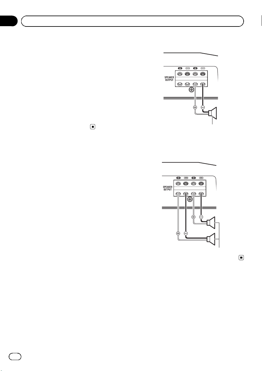
Connecting the spea kers
This amplifier can be connected to two speakers in parallel. Connect the speaker leads to
suit the mode according to the figure shown
below.
Precautions for parallel connection
! When wiring two speakers in parallel, make
sure that the synthetic impedance is from
1 W to 8 W to prevent the amplifier from
catching fire, generating smoke and/or
being damaged.
! When connected in parallel with the syn-
thetic impedance less than 1 W, as a nor-
mal function, this amplifier may
automatically be set on mute if outputting
high volume sound. Turn down the volume
until the mute function is canceled.
When connecting to one speaker
Speaker output
When connecting to two speakers
The output from two speakers is the same as
that of one speaker.
Speaker output
8
En
Page 9
Connecting the units
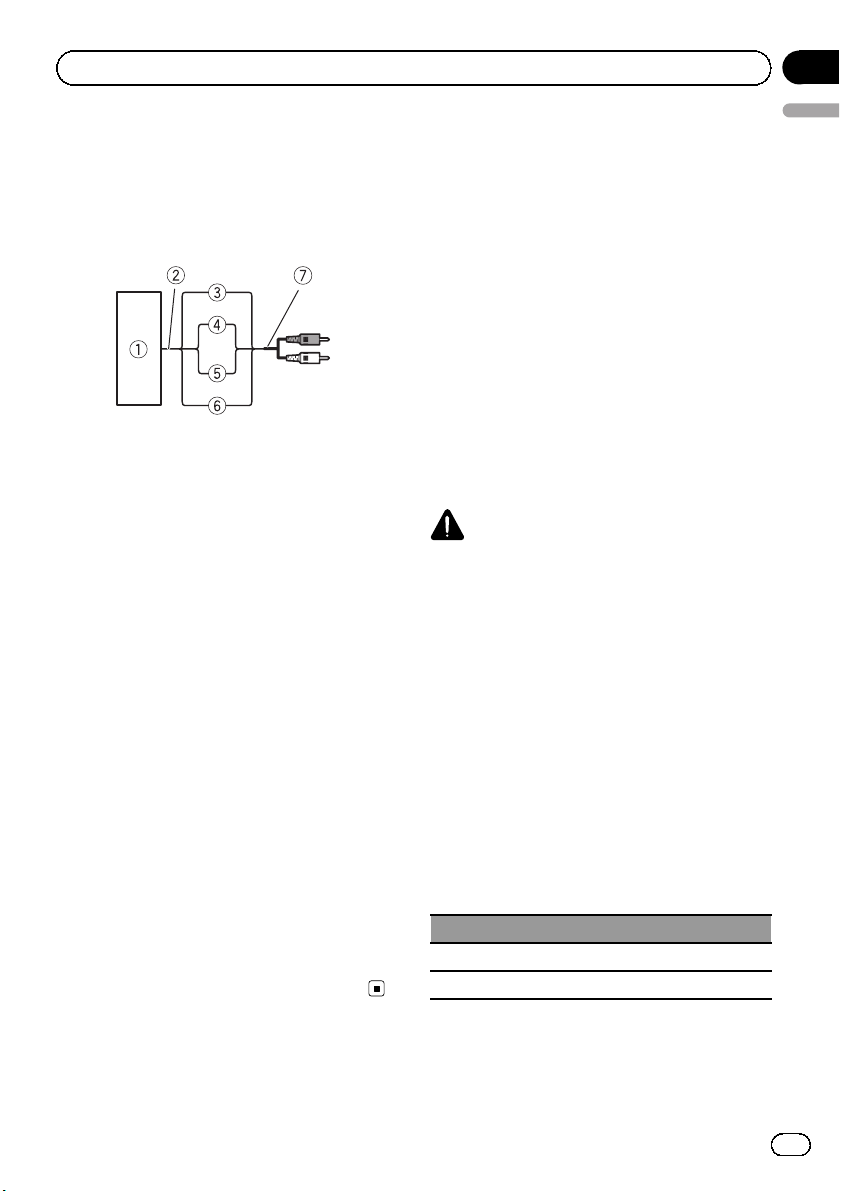
Connections when using
the speaker input wire
Connect the car stereo speaker output wires
to the amplifier using the supplied speaker
input wire with RCA pin cord.
1 Car Stereo
2 Speaker output
3 Red: Right +
4 Black: Right *
5 Black: Left *
6 White: Left +
7 Speaker input wire with RCA pin cord
To the RCA input jack of this unit
Notes
! If speaker wires with an RCA pin cord from a
headunit are connected to this amplifier, the
amplifier will automatically turn on when the
headunit is turned on. When the headunit is
turned off, the amplifier turns off automatically. This function may not work with some
headunits. In such cases, please use a system remote control wire (sold separately). If
multiple amplifiers are to be connected together synchronously, connect the head unit
and all amplifiers via the system remote control wire.
! Connect the system remote control wire when
you wish to only turn on the car stereo, not the
amplifier.
! This amplifier automatically selects an input
signal mode between the RCA level and the
speaker level by detecting an input signal.
Section
03
English
Solderless terminal
connections
! Since the wire will become loose over time,
it must be periodically inspected and tightened as necessary.
! Do not solder or bind the ends of the
twisted wires.
! Fasten while making sure to not to clamp
the insulating sheath of the wire.
! Use the supplied hexagonal wrench to
tighten and loosen the terminal screw of
the amplifier and use it to securely fasten
the wire. Be careful to avoid excessive tightening of this screw, which may damage
the wire.
Connecting the power terminal
WARNING
If the batter y wire is not securely fixed to the terminal using the terminal screws, there is a risk of
overheating, malfunction and injury, including
minor burns.
! Always use the recommended battery and
ground wire, which is sold separately. Connect the battery wire directly to the car battery positive (+) terminal and the ground
wire to the car body.
! Recommended wires size (AWG: American
Wire Gauge) is as follows. The battery wire,
the ground wire and the optional direct
ground wire must be same size.
! Use a wire of 8 AWG to 16 AWG wire for the
speaker wire.
Battery wire and ground wire size
Wire length Wire size
less than 3.6 m (11 ft. 10 in.) 6 AWG
less than 6.4 m (20 ft. 12 in.) 4 AWG
En
9
Page 10
Section
03
Connecting the units
1 Route battery wire from engine compartment to the vehicle interior.
! When drilling a cable pass-hole into the ve-
hicle body and routing a battery wire thorough it, take care not to short-circuit the
wire damaging it by the cut edges or burrs
of the hole.
After completing all other amplifier connections, finally connect the battery wire terminal
of the amplifier to the positive (+) battery
terminal.
2
1
1 Positive (+) terminal
2 Battery wire (sold separately)
The maximum length of the wire between
the fuse and the positive + terminal of the
battery is 30 cm (12 in.).
3 Fuse 100 A (GM-D8601) / 150 A (GM-D9601)
(sold separately)
Each amplifier must be separately fused at
100 A (GM-D8601) / 150 A (GM-D9601).
3
2 Use wire cutters or a utility knife to
strip the end of the battery wire, ground
wire and system remote control wire to expose about 10 mm (3/8 in.) of the end of
each of the wires, and then twist the exposed ends of the wires.
Twist
10 mm (3/8 in.)
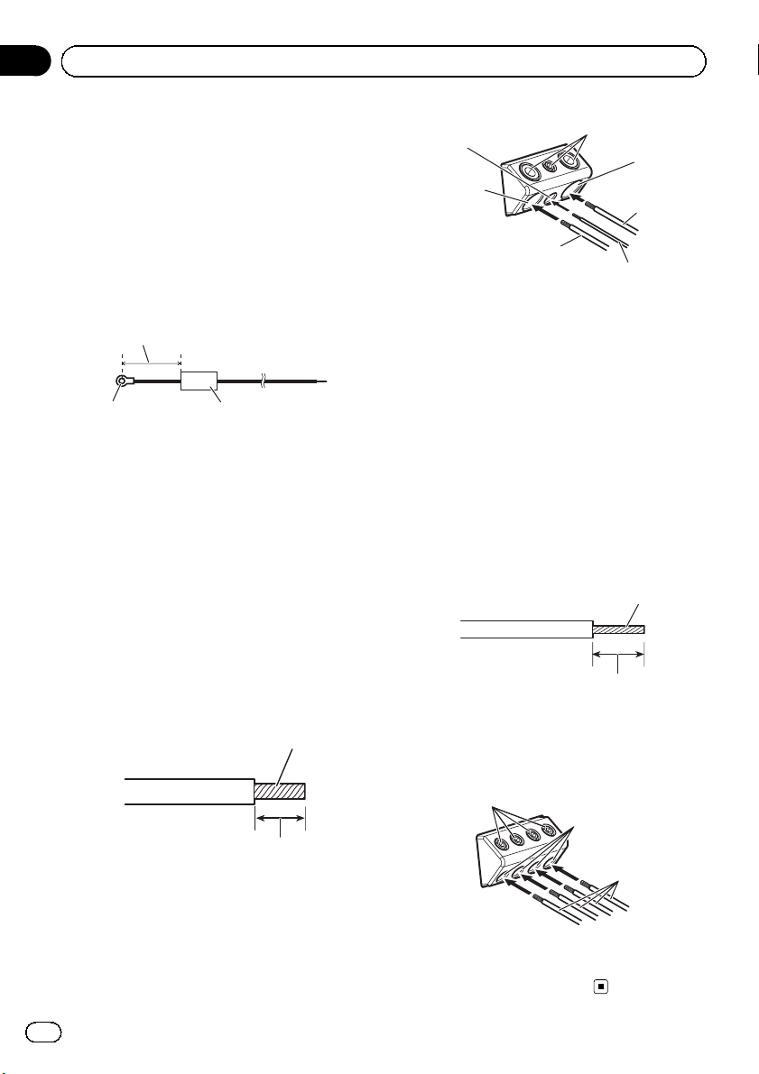
3 Connect the wires to the terminal.
Fix the wires securely with the terminal
screws.
6
7
2
4
1
3
5
1 Battery wire
2 Power terminal
3 Ground wire
4 GND terminal
5 System remote control wire
6 System remote control terminal
7 Terminal screws
Connecting the speaker output
terminals
1 Use wire cutters or a utility knife to
strip the end of the speaker wires to expose about 10 mm (3/8 in.) of wire and
then twist the wire.
Twist
10 mm (3/8 in.)
2 Connect the speaker wires to the
speaker output terminals.
Fix the wires securely with the terminal
screws.
1
3
2
10
1 Terminal screws
2 Speaker wires
3 Speaker output terminals
En
Page 11
Installation
Before installing the amplifier
WARNING
! To ensure proper installation, use the supplied
parts in the manner specified. If any parts
other than those supplied are used, they may
damage internal parts of the amplifier, or become loose causing the amplifier to shut
down.
! Do not install in:
— Places where it could injure the driver or
passengers if the vehicle stops suddenly.
— Places where it may interfere with the dri-
ver, such as on the floor in front of the driver’s seat.
! Install tapping screws in such a way that the
screw tip does not touch any wire. This is important to prevent wires from being cut by vibration of the car, which can result in fire.
! Make sure that wires do not get caught in the
sliding mechanism of the seats or touch the
legs of a person in the vehicle as short-circuit
may result.
! When drilling to install the amplifier, always
confirm no parts are behind the panel and
protect all cables and important equipment
(e.g. fuel/brake lines, wiring) from damage.
CAUTION
! To ensure proper heat dissipation of the ampli-
fier, ensure the following during installation:
— Allow adequate space above the amplifier
for proper ventilation.
— Do not cover the amplifier with a floor mat
or carpet.
! Place all cables away from hot places, such
as near the heater outlet.
! The optimal installation location differs de-
pending on the car model. Secure the amplifier at a sufficiently rigid location.
! Check all connections and systems before
final installation.
! After installing the amplifier, confirm that the
spare tire, jack and tools can be easily removed.
Section
04
English
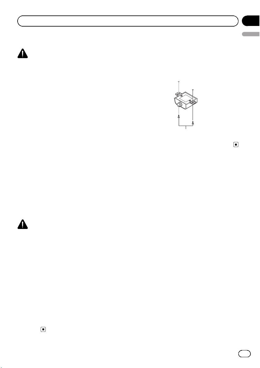
Attaching the Bass boost
remote control
Attach with tapping screws (3 mm × 10 mm
(1/8 in. × 3/8in.)) at an easily accessible location such as under the dashboard.
Tapping screws (3 mm × 10 mm
(1/8 in. × 3/8 in.))
Example of installation on
the floor mat or chassis
1 Place the amplifier in the desired installation location.
Insert the supplied tapping screws (4 mm ×
18 mm (5/32 in. × 3/4in.)) into the screw holes
and push on the screws with a screwdriver so
they make an imprint where the installation
holes are to be located.
2 Drill 2.5 mm (3/32 in.) diameter holes at
the imprints either on the carpet or directly
on the chassis.
En
11
Page 12
Section
04
Installation
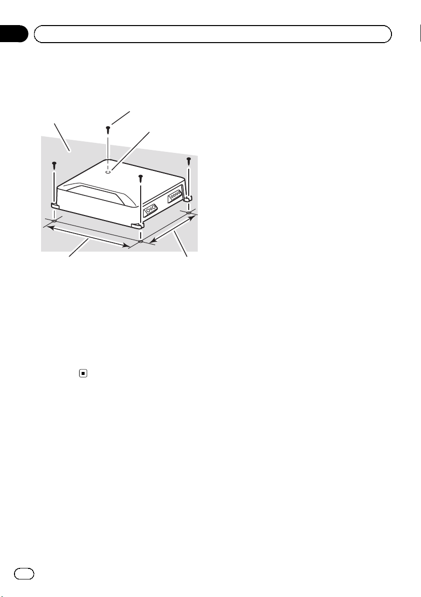
3 Install the amplifier with the use of
supplied tapping screws (4 mm × 18 mm
( 5/32 in. × 3/4 in.)).
1
3
45
1 Tapping-screws (4 mm × 18 mm (5/32 in. ×
3/4 in.))
2 Drill a 2.5 mm (3/32in.) diameter hole.
3 Floor mat or chassis
4 Hole-to-hole distance: 257 mm (10-1/8in.)
(GM-D8601) / 307 mm (12-1/8 in.) (GMD9601)
5 Hole-to-hole distance: 181 mm (7-1/8in.)
(GM-D8601) / 181 mm (7-1/8 in.) (GMD9601)
2
12
En
Page 13

Additional information
Appendix
Specifications
GM-D8601
Power source ............................. 14.4 V DC (10.8 V to 15.1 V
allowable)
Grounding system ................... Negative type
Current consumption ............ 24 A (at continuous power,
4 W)
Average current drawn ......... 2.9 A (4 W for one channel)
4.0 A (2 W for one channel)
6.0 A (1 W for one channel)
Fuse ................................................ 40 A × 2
Dimensions (W × H × D) ... 265 mm × 60 mm ×
200 mm
(10-3/8 in. × 2-3/8 in. ×
7-7/8 in.)
Weight .......................................... 2.7 kg (6lbs)
(Leads for wiring not included)
Maximum power output ....... 600 W × 1 (4 W)/1600W×
1(1W)
Continuous power output ... 300 W × 1 (at 14.4 V, 4W,
20 Hz to 240Hz, ≦ 1 % THD)
500 W × 1 (at 14.4V, 2 W,
100 Hz, ≦ 1% THD)
800 W × 1 (at 14.4V, 1 W,
100 Hz, ≦ 1% THD)
Load impedance ...................... 4W (1 W to 8W allowable)
Frequency response ............... 10 Hz to 240 Hz (+0 dB,
–3 dB)
Signal-to-noise ratio ............... 100 dB (IHF-A network)
Low pass filter:
Cut off frequency ........... 40 Hz to 240 Hz
Cut off slope ..................... –12 dB/oct
Bass boost:
Frequency .......................... 50 Hz
Level ..................................... 0dBto18dB
Gain control:
RCA ...................................... 200 mV to 6.5 V
Speaker .............................. 0.8 V to 16 V
Maximum input level / impedance:
RCA ...................................... 6.5 V / 25 kW
Speaker .............................. 16 V / 12 kW
CEA2006 Specifications
Power output ............................. 300 W RMS × 1 Channel (at
14.4 V, 4 W, 20 Hz to 240 Hz
and ≦ 1 % THD+N)
500 W RMS × 1 Channel (at
14.4 V, 2 W, 100 Hz and ≦ 1%
THD+N)
800 W RMS × 1 Channel (at
14.4 V, 1 W, 100 Hz and ≦ 1%
THD+N)
S/N ratio ....................................... 75 dBA (reference: 1 W into
4 W)
GM-D9601
Power source ............................. 14.4 V DC (10.8 V to 15.1 V
allowable)
Grounding system ................... Negative type
Current consumption ............ 39 A (at continuous power,
4 W)
Average current drawn ......... 3.7 A (4 W for one channel)
5.2 A (2 W for one channel)
7.5 A (1 W for one channel)
Fuse ................................................ 40 A × 3
Dimensions (W × H × D) ... 315 mm × 60 mm ×
200 mm
(12-3/8 in. × 2-3/8 in. ×
7-7/8 in.)
Weight .......................................... 3.3 kg (7.3lbs)
(Leads for wiring not included)
Maximum power output ....... 1 000 W × 1 (4 W) / 2 400 W
×1(1W)
Continuous power output ... 500 W × 1 (at 14.4 V, 4W,
20 Hz to 240Hz, ≦ 1 % THD)
800 W × 1 (at 14.4V, 2 W,
100 Hz, ≦ 1% THD)
1 200W × 1 (at 14.4 V, 1 W,
100 Hz, ≦ 1% THD)
Load impedance ...................... 4W (1 W to 8W allowable)
Frequency response ............... 10 Hz to 240 Hz (+0 dB,
–3 dB)
Signal-to-noise ratio ............... 100 dB (IHF-A network)
Low pass filter:
Cut off frequency ........... 40 Hz to 240 Hz
Cut off slope ..................... –12 dB/oct
Bass boost:
Frequency .......................... 50 Hz
Level ..................................... 0dBto18dB
Gain control:
RCA ...................................... 200 mV to 6.5 V
Speaker .............................. 0.8 V to 16 V
Maximum input level / impedance:
RCA ...................................... 6.5 V / 25 kW
Speaker .............................. 16 V / 12 kW
English
En
13
Page 14

Appendix
Additional information
CEA2006 Specifications
Power output ............................. 500 W RMS × 1 Channel (at
S/N ratio ....................................... 75 dBA (reference: 1 W into
14.4 V, 4 W, 20 Hz to 240 Hz
and ≦ 1 % THD+N)
800 W RMS × 1 Channel (at
14.4 V, 2 W, 100 Hz and ≦ 1%
THD+N)
1 200W RMS × 1 Channel
(at 14.4 V, 1W, 100 Hz and ≦
1 % THD+N)
4 W)
Notes
! Specifications and the design are subject to
modifications without notice.
! The average current drawn is nearly the maxi-
mum current drawn by this unit when an
audio signal is input. Use this value when
working out total current drawn by multiple
power amplifiers.
14
En
Page 15

Avant de commencer
Section
01
Nous vous remercions d’avoir acheté cet
appareil PIONEER.
Pour garantir une utilisation correcte, lisez
bien ce mode d’emploi avant d’utiliser cet appareil. Il est particulièrement important que
vous lisiez et respectiez les indications AT-
TENTION et PRÉCAUTION de ce mode
d’emploi. Conser vez-le dans un endroit sûr et
facilement accessible pour toute consultation
ultérieure.
Service après-vente de s
produits Pioneer
Veuillez contacter le revendeur ou le distributeur auprès duquel vous avez acheté cet appareil pour le service après-vente (y compris les
conditions de garantie) ou pour toute autre information. Dans le cas où les informations nécessaires ne sont pas disponibles, veuillez
contacter les sociétés indiquées ci-dessous :
N’expédiez pas l’appareil pour réparation à
l’une des adresses figurant ci-dessous sans
avoir pris contact au préalable.
États-Unis
Pioneer Electronics (USA) Inc.
CUSTOMER SUPPORT DIVISION
P.O. Box 1760
Long Beach, CA 90801-1760
800-421-1404
CANADA
Pioneer Électroniques du Canada, Inc.
DÉPARTEMENT DE SERVICE AUX CONSOMMATEURS
340 Ferrier Street
Unit 2
Markham, Ontario L3R 2Z5, Canada
1-877-283-5901
905-479-4411
Pour connaître les conditions de garantie, reportez-vous au document Garantie limitée qui
accompagne cet appareil.
Si vous rencontrez des
problèmes
En cas d’anomalie, consultez le distributeur
ou le service d’entretien agréé par Pioneer le
plus proche.
Visitez notre site Web
http://www.pioneerelectronics.com
au Canada
http://www.pioneerelectronics.ca
! Informez-vous sur les mises à jour disponi-
bles pour votre produit (telles que les mises
à jour du firmware).
! Enregistrez votre produit afin de recevoir
des notifications concernant les mises à
jour du produit, ainsi que pour sauvegarder
les détails de votre achat dans nos fichiers
en cas de perte ou de vol.
! Accédez aux modes d’emploi, aux informa-
tions relatives aux pièces de rechange et à
l’entretien, et à beaucoup d’autres
informations.
Français
15
Fr
Page 16

Section
01
Avant de commencer
La protection de votre ouïe
est entre vos mains
Pour assurer le rendement optimal de votre
matériel et – plus important encore – la protection de votre ouïe, réglez le volume à un niveau
raisonnable. Pour ne pas altérer votre sens de
la perception, le son doit être clair mais ne
produire aucun vacarme et être exempt de
toute distorsion. Votre ouïe peut vous jouer
des tours. Avec le temps, votre système auditif
peut en effet s’adapter à des volumes supérieurs, et ce qui vous semble un « niveau de
confort normal » pourrait au contraire être excessif et contribuer à endommager votre ouïe
de façon permanente. Le réglage de votre matériel à un volume sécuritaire AVANT que votre
ouïe s’adapte vous permettra de mieux vous
protéger.
CHOISISSEZ UN VOLUME SÉCURITAIRE :
! Réglez d’abord le volume à un niveau infé-
rieur.
! Montez progressivement le volume jusqu’à
un niveau d’écoute confortable; le son doit
être clair et exempt de distorsions.
! Une fois que le son est à un niveau confor-
table, ne touchez plus au bouton du volume.
N’OUBLIEZ PAS DE RESPECTER LES
DIRECTIVES SUIVANTES:
! Lorsque vous montez le volume, assurez-
vous de pouvoir quand même entendre ce
qui se passe autour de vous.
! Faites très attention ou cessez temporaire-
ment l’utilisation dans les situations pouvant s’avérer dangereuses.
! N’utilisez pas des écouteurs ou un casque
d’écoute lorsque vous opérez un véhicule
motorisé ; une telle utilisation peut créer
des dangers sur la route et est illégale à de
nombreux endroits.
Quelques mots sur cet appareil
Ce produit est un amplificateur mono pour hautparleur d’extrêmes graves. Si les canaux L (gauche) et D (droit) sont tous les deux connectés à
l’entrée RCA de ce produit, la sortie sera combinée étant donné que ce produit est un amplificateur mono.
Avant de connecter/
d’installer l’amplificateur
ATTENTION
! Cet appareil est utilisable sur des véhicules
équipés d’une batterie 12 V avec mise à la
masse du négatif. Vérifiez la tension de la batterie avant l’installation dans des véhicules de
caravaning, des camions ou des bus.
! Lors de l’installation de cet appareil, veillez à
connecter d’abord le fil de masse. Assurezvous que le fil de masse est connecté correctement aux parties métalliques de la carrosserie du véhicule. Le fil de masse de cet appareil
doit être connecté indépendamment au véhicule à l’aide de vis différentes. Si la vis du fil
de masse se desserre ou tombe, il peut en résulter un incendie, de la fumée ou un dysfonctionnement.
! Assurez-vous de bien installer le fusible sur le
fil de la batterie.
! Utilisez toujours un fusible correspondant aux
caractéristiques spécifiées. L’utilisation d’un
fusible incorrect peut entraîner une surchauffe et de la fumée, des dommages au niveau du produit et des blessures, incluant des
brûlures.
! Vérifiez les connexions de l’alimentation et
des haut-parleurs en cas de rupture du fusible
du fil de batterie vendu séparément ou de
l’amplificateur. Déterminez la cause et résolvez le problème, puis remplacez le fusible par
un fusible identique.
16
Fr
Page 17

Avant de commencer
Section
01
! Installez toujours l’amplificateur sur une sur-
face plane. N’installez pas l’amplificateur sur
une surface qui n’est pas plane ou sur une
surface présentant une saillie. Ceci pourrait
entraîner un dysfonctionnement.
! Lors de l’installation de l’amplificateur, ne lais-
sez pas des pièces telles que des vis supplémentaires se coincer entre l’amplificateur et
l’automobile. Ceci pourrait entraîner un dysfonctionnement.
! Ne laissez pas cet appareil entrer en contact
avec des liquides. Cela pourrait provoquer une
électrocution. Tout contact avec des liquides
pourrait aussi provoquer des dommages, de
la fumée et une surchauffe de l’appareil.
Les surfaces de l’amplificateur et des hautparleurs connectés peuvent également chauffer et entraîner des brûlures mineures.
! En cas d’événement anormal, l’alimentation
de l’amplificateur est coupée de manière à éviter tout dysfonctionnement de l’équipement.
Dans ce cas, coupez l’alimentation du système et vérifiez les connexions de l’alimentation et des haut-parleurs. Si vous n’êtes pas
en mesure de déterminer la cause, veuillez
contacter votre revendeur.
! Déconnectez toujours la borne négative * de
la batterie préalablement, de manière à éviter
tout risque de choc électrique ou de court-circuit lors de l’installation.
! N’essayez pas de démontez ou de modifiez
cet appareil. Ceci pourrait provoquer un incendie, une électrocution ou tout autre dysfonctionnement.
D9601) ou plus et une impédance de 4 W ;2:
un haut-parleur d’extrêmes graves avec une
entrée nominale de 500 W (GM-D8601) / 800 W
(GM-D9601) ou plus et une impédance de 2 W
ou 3 : un haut-parleur d’extrêmes graves avec
une entrée nominale de 800W (GM-D8601) /
1 200 W (GM-D9601) ou plus et une impédance de 1 W.
Si l’ entrée nominale et l’impédance sont en
dehors des plages ci-dessus, le haut-parleur
d’extrêmes graves risque de prendre feu, de
dégager de la fumée ou d’être endommagé.
Quelques mots sur la fonction de
protection
Ce produit est doté d’une fonction de protection.
Lorsque ce produit détecte une anomalie, les
fonctions suivantes permettent de protéger le
produit et la sortie du haut-parleur.
! L’indicateur POWER/PROTECT devient rouge
et l’amplificateur se met hors service dans les
situations indiquées ci-dessous.
— Si la température à l’intérieur de l’amplifi-
cateur est trop élevée.
— Si une tension CC est appliquée à la borne
de sortie des haut-parleurs.
! L’indicateur POWER/PROTECT devient rouge
et le son de la sortie est coupé dans les situations indiquées ci-dessous.
— Si la borne de sortie des haut-parleurs et le
fil du haut-parleur sont en court-circuit.
Français
PRÉCAUTION
! Maintenez le niveau d’écoute à une valeur
telle que vous puissiez entendre les sons provenant de l’extérieur.
! L’utilisation prolongée du système stéréo du
véhicule lorsque le moteur est à l’arrêt ou au
ralenti peut épuiser la batterie.
! Connectez l’un des trois haut-parleurs d’extrê-
mes graves à l’amplificateur ; 1 : un haut-parleur d’extrêmes graves avec une entrée
nominale de 300 W (GM-D8601) / 500 W (GM-
17
Fr
Page 18

Section
02
Réglage de l’appareil
Description de l’ap pareil
GM-D8601
Face avant
21 3 4
Face arrière
GM-D9601
Face avant
21 3 4
Face arrière
Si nécessaire, utilisez un tournevis plat pour
régler le commutateur.
1 Indicateur POWER/PROTECT
L’indicateur de mise sous tension s’allume
pour indiquer la mise sous tension.
! L’indicateur devient rouge en cas d’ano-
malie.
de l’augmentation du volume du système
stéréo du véhicule, tournez les commandes
vers un niveau plus élevé.
! Procédez au réglage sur la position
NORMAL pour l’utilisation avec un sys-
tème stéréo de véhicule équipé d’une
sortie RCA (sortie standard de 500 mV).
Pour l’utilisation avec un système stéréo
de véhicule Pioneer équipé d’une sortie
RCA, dont la sortie maximale est de 4 V
ou plus, réglez le niveau en fonction de
celui de sortie du système stéréo du véhicule.
! Procédez au réglage sur la position H
pour l’utilisation avec un système stéréo
de véhicule équipé d’une sortie de 4 V.
! Si la quantité de parasites est trop impor-
tante lors de l’utilisation des bornes d’entrée des haut-parleurs, tournez la
commande de gain à un niveau plus
élevé.
3 Commande de fréquence de coupure
LPF (filtre passe-bas)
Vous pouvez sélectionner une fréquence de
coupure de 40Hz à 240 Hz.
4 Jack BASS BOOST REMOTE (télécommande du niveau d’accentuation des graves)
En connectant la télécommande du niveau
d’accentuation des graves au jack de l’appareil central, vous pourrez sélectionner le niveau d’accentuation de graves entre 0 dB et
18 dB.
Pour des instructions sur la connexion de la
télécommande du niveau d’accentuation
des graves à l’amplificateur, reportez-vous à
la page 20, Schéma de connexion.
2 Commande GAIN (gain)
Si la sortie reste faible alors que le volume
du système stéréo du véhicule a été augmenté, tournez les commandes vers un niveau plus faible. En cas de distorsion lors
18
Fr
Page 19

Réglage de l’appareil
Section
02
Réglage correct du gain
! Fonction de protection incluse pour éviter
tout dysfonctionnement de l’appareil et/ou
des haut-parleurs lié à une sortie excessive
ou à une utilisation ou une connexion incorrecte.
! Lors de l’émission de sons à haut volume,
etc., cette fonction coupe l’émission pendant quelques secondes. L’émission est cependant rétablie une fois le volume de
l’appareil central baissé.
! Une coupure de la sortie son peut indiquer
un réglage incorrect de la commande de
gain. Afin de garantir une émission sonore
continue lorsque le volume de l’appareil
central est élevé, réglez la commande de
gain de l’amplificateur à un niveau adapté
au niveau de sortie maximal de la sortie
préamp de l’appareil central de manière à
ce que le volume ne nécessite aucune modification et à ce que les sorties excessives
soient contrôlées.
! Le son de l’appareil est régulièrement
coupé alors que les réglages du gain et du
volume sont corrects. Dans de tels cas,
veuillez contacter le Centre d’entretien
agréé par Pioneer le plus proche.
Commande de gain de l’appareil
Niveau de préamp : 2 V (standard: 500 mV)
Relation entre le gain de
l’amplificateur et la puissance de
sortie de l’appareil central
Français
Si le gain de l’amplificateur est augmenté de
manière incorrecte, les distorsions augmentent sans que la puissance soit beaucoup plus
importante.
Forme de signal lors de l’émission à
volume élevé avec la commande de
gain de l’amplificateur
Forme de signal distordu avec sortie élevée, si
vous augmentez le gain de l’amplificateur, la
puissance n’est que légèrement modifiée.
Niveau de préamp : 4 V
L’illustration ci-dessus représente le réglage
de gain NORMAL.
19
Fr
Page 20

Section
03
Connexion des appa reils
Schéma de connexion
2
1
1 Fil de la batterie (vendu séparément)
3
5
a
e
h
f
! La longueur maximale du fil entre le fu-
sible et la borne positive + de la batterie
est de 30cm.
! Pour connaître la taille du fil, reportez-
vous à la page 22, Connexion de la borne
d’alimentation. Le fil de la batterie, le fil
de terre et le fil de terre directe en option
doivent être de la même taille. Une fois
toutes les autres connexions à l’amplificateur effectuées, connectez la borne
du fil de la batterie de l’amplificateur à
la borne positive + de la batterie.
2 Fusible 100 A (GM-D8601) / 150 A (GM-D9601)
(vendu séparément)
Chaque amplificateur doit être doté d’un fusible distinct de 100 A (GM-D8601) / 150 A
(GM-D9601).
3 Borne positive (+)
4 Borne négative (*)
5 Batterie (vendue séparément)
6 Fil de terre, borne (vendu séparément)
Les fils de terre doivent être de la même taille
que le fil de la batterie.
7
6
4
9
d
g
8
b
c
i
j
À connecter au châssis ou à la carrosserie en
métal.
7 Système stéréo de véhicule avec jacks de sor-
tie RCA (vendu séparément)
8 Sortie externe
9 Fil de connexion avec prises RCA (vendu sépa-
rément)
a Amplificateur avec jacks d’entrée RCA (vendu
séparément)
b Télécommande du niveau d’accentuation des
graves
c Fil de la télécommande du niveau d’accentua-
tion des graves (5 m)
d Jack d’entrée RCA
e Jack de sortie RCA
f Fil de la télécommande du système (vendu sé-
parément)
Connectez la borne mâle du fil à la borne de
la télécommande du système stéréo du véhicule. La borne femelle peut être connectée à
la prise de commande du relais de l’antenne
motorisée. Si le système stéréo du véhicule ne
dispose pas d’une borne de télécommande,
connectez la borne mâle à la borne d’alimentation via le contact d’allumage.
g Bornes de sortie des haut-parleurs
Veuillez vous reporter à la section suivante
pour les instructions de connexion des hautparleurs. Reportez-vous à la page 22, Conne-
xions lors de l’utilisation du fil d’entrée des
haut-parleurs.
h Fusible 40 A × 2 (GM-D8601) / 40 A × 3 (GM-
D9601)
i Face avant
j Face arrière
Avant de connecter
l’amplificateur
ATTENTION
! Fixez le câblage avec des serre-fils ou de la
bande adhésive. Pour protéger le câblage, enroulez les sections en contact avec des pièces
en métal dans du ruban adhésif.
20
Fr
Page 21

Connexion des appa reils
Section
03
! Ne découpez jamais l’isolation de l’alimenta-
tion pour alimenter d’autres équipements. La
capacité en courant du fil est limitée.
PRÉCAUTION
! Ne raccourcissez jamais aucun fil, faute de
quoi le circuit de protection risque de fonctionner de manière incorrecte.
! Ne câblez jamais le câble négatif du haut-par-
leur directement à la masse.
! Ne réunissez jamais ensemble les câbles né-
gatifs de plusieurs haut-parleurs.
! Si le fil de la télécommande du système de
l’amplificateur est connecté à la borne d’alimentation via le contact d’allumage (12 V CC),
l’amplificateur reste sous tension que le système stéréo du véhicule soit allumé ou non,
ce qui peut épuiser la batterie lorsque le moteur est à l’arrêt ou au ralenti.
! Installez et positionnez le fil de batterie vendu
séparément aussi loin que possible des fils de
haut-parleurs.
Installez et positionnez le fil de batterie vendu
séparément, le fil de terre, les fils de haut-parleurs et l’amplificateur aussi loin que possible
de l’antenne, du câble d’antenne et du
syntoniseur.
ment normal, le son de cet amplificateur
peut automatiquement être coupé en cas
d’émission d’un son à volume élevé. Baissez le volume jusqu’à ce que la fonction de
coupure du son soit annulée.
Lors de la connexion à un haut-parleur
Sortie des haut-parleurs
Lors de la connexion à deux hautparleurs
La sortie des deux haut-parleurs est identique
à celle d’un haut-parleur.
Français
Connexion des haut-parleurs
Cet amplificateur peut être connecté à deux
haut-parleurs en parallèle. Connectez les fils
des haut-parleurs en fonction du mode selon
l’illustration ci-dessous.
Précautions à prendre pour une
connexion parallèle
! Lorsque vous branchez deux haut-parleurs
en parallèle, assurez-vous que l’impédance
synthétique est comprise entre 1 W à8W
pour éviter que l’amplificateur ne prenne
feu, ne dégage de la fumée et/ou ne soit
endommagé.
! Lorsqu’il est connecté en parallèle avec
une impédance synthétique inférieure à
1 W, à savoir en condition de fonctionne-
Sortie des haut-parleurs
21
Fr
Page 22

Section
03
Connexion des appa reils
Connexions lors de
l’utilisation du fil d’entrée
des haut-parleurs
Connectez les fils de sortie des haut-parleurs
du système stéréo du véhicule à l’amplificateur à l’aide du fil d’entrée des haut-parleurs
fourni, avec cordon RCA.
1 Système stéréo du véhicule
2 Sortie des haut-parleurs
3 Rouge : + droit
4 Noir : * droit
5 Noir : * gauche
6 Blanc : + gauche
7 Fil d’entrée des haut-parleurs avec cordon
RCA
Vers le jack d’entrée RCA de cet appareil
Remarques
! Si les fils des haut-parleurs avec cordon RCA
d’un appareil central sont connectés à cet amplificateur, l’amplificateur se met automatiquement en service lorsque l’appareil central
est mis en service. Lorsque l’appareil central
est mis hors service, l’amplificateur se met automatiquement hors service. Cette fonction
peut ne pas fonctionner sur certains appareils
centraux. Dans ce cas, utilisez le fil d’une télécommande du système (vendu séparément).
Si plusieurs amplificateurs sont connectés de
manière synchrone, reliez l’appareil central et
tous les amplificateurs via le fil de la télécommande du système.
! Connectez le fil de la télécommande du sys-
tème lorsque vous souhaitez mettre le système stéréo du véhicule sous tension, et non
l’amplificateur.
! Cet amplificateur sélectionne automatique-
ment un mode de signal d’entrée entre le niveau RCA et le niveau de haut-parleur en
détectant un signal d’entrée.
Connexions de bornes sans
soudure
! Etant donné que le fil se relâche dans le
temps, il doit être inspecté régulièrement et
resserré si nécessaire.
! Ne soudez et ne pliez pas les extrémités
des fils tordus.
! Lors du serrage, veillez à ne pas coincer la
gaine isolante du fil.
! Utilisez la clé hexagonale fournie pour ser-
rer et desserrer la vis de la borne de l’amplificateur et pour serrer fermement le fil.
Veillez à ne pas trop serrer la vis, faute de
quoi le fil pourrait être endommagé.
Connexion de la borne
d’alimentation
ATTENTION
Si le fil de la batterie n’est pas fermement fixé à la
borne à l’aide des vis de la borne, des risques de
surchauffe, d’anomalie de fonctionnement et de
blessures, brûlures mineures incluses, existent.
! Utilisez toujours le fil de la batterie et le fil
de terre recommandés, qui sont vendus séparément. Connectez le fil de la batterie directement sur la borne positive (+)dela
batterie du véhicule et le fil de terre sur la
carrosserie du véhicule.
! La taille de fils recommandée (AWG : Ame-
rican Wire Gauge) est la suivante. Le fil de
la batterie, le fil de terre et le fil de terre directe en option doivent être de la même
taille.
! Utilisez un fil de 8 AWG à 16 AWG pour les
haut-parleurs.
22
Fr
Page 23

Connexion des appa reils
Section
03
Taille du fil de terre et du fil de batterie
Longueur du fil Taille du fil
moins de 3,6 m 6 AWG
moins de 6,4 m 4 AWG
1 Positionnez le fil de la batterie du
compartiment du moteur jusqu’àl’intérieur
du véhicule.
! Lors du perçage d’un trou de passage des
câbles dans la carrosserie du véhicule et le
passage d’un fil de la batterie à travers
celui-ci, veillez à ne pas créer un court-circuit du fil en l’endommageant avec les
bords coupants ou les bavures du trou.
Une fois toutes les autres connexions de l’amplificateur effectuées, connectez la borne du
fil de batterie de l’amplificateur à la borne positive (+) de la batterie.
2
1
1 Borne positive (+)
2 Fil de la batterie (vendu séparément)
La longueur maximale du fil entre le fusible
et la borne positive + de la batterie est de
30 cm.
3 Fusible 100 A (GM-D8601) / 150 A (GM-
D9601) (vendu séparément)
Chaque amplificateur doit être doté d’un fusible distinct de 100 A (GM-D8601) / 150 A
(GM-D9601).
3
2 Utilisez une pince coupante ou un couteau à lame rétractable pour dénuder l’extrémité du fil de la batterie, connectez le fil
de terre et le fil de la télécommande afin
d’exposer environ 10 mm à l’extrémité de
chacun des fils, puis torsadez les extrémités
exposées des fils.
Torsadez
10 mm
3 Connectez les fils à la borne.
Fixez fermement les fils à l’aide des vis de la
borne.
7
6
2
4
1
3
5
1 Fil de la batterie
2 Borne d’alimentation
3 Fil de terre
4 Borne de terre
5 Fil de la télécommande du système
6 Borne de la télécommande du système
7 Vis de la borne
Français
23
Fr
Page 24

Section
03
Connexion des appa reils
Connexion des bornes de sortie
des haut-parleurs
1 Utilisez une pince coupante ou un couteau à lame rétractable pour dénuder l’extrémité des fils des haut-parleurs et
exposer environ 10 mm de fil, puis torsadez
le fil.
Torsadez
10 mm
2 Connectez les fils des haut-parleurs aux
bornes de sortie des haut-parleurs.
Fixez fermement les fils à l’aide des vis de la
borne.
1
3
1 Vis de la borne
2 Fils des haut-parleurs
3 Bornes de sortie des haut-parleurs
24
Fr
2
Page 25

Installation
Section
04
Avant d’installer
l’amplificateur
ATTENTION
! Afin de garantir une installation correcte, utili-
sez les pièces fournies de la manière indiquée. Si vous utilisez des pièces autres que
celles fournies, celles-ci risquent d’endommager des pièces internes de l’amplificateur ou
peuvent se desserrer, ce qui entraînerait l’arrêt
de l’amplificateur.
! Ne procédez pas à l’installation dans:
— Des emplacements où l’appareil peut bles-
ser le conducteur ou les passagers en cas
d’arrêt soudain du véhicule.
— Des emplacements où l’appareil peut
gêner le conducteur, tels que sur le sol devant le siège du conducteur.
! Installez les vis autotaraudeuses de telle ma-
nière que la pointe des vis n’entre en contact
avec aucun fil. Cela est important pour éviter
toute coupure des fils par les vibrations du véhicule, ce qui pourrait entraîner un incendie.
! Assurez-vous que les fils ne sont pas coincés
dans le mécanisme coulissant des sièges ou
ne touchent pas les jambes d’un passager,
car cela pourrait entraîner un court-circuit.
! Lorsque vous percez pour installer l’amplifica-
teur, vérifiez toujours qu’il n’y a aucune pièce
derrière le panneau et que tous les câbles et
équipements importants (conduites de carburant/freinage, câblage, par exemple) sont protégés des dommages.
PRÉCAUTION
! Afin de garantir une dissipation de la chaleur
correcte au niveau de l’amplificateur, vérifiez
les points suivants lors de l’installation :
— Laissez suffisamment de place au-dessus
de l’amplificateur pour permettre une ventilation correcte.
— Ne couvrez pas l’amplificateur avec un
tapis de sol ou de la moquette.
! Placez les câbles à l’écart de tous les endroits
chauds, par exemple les sorties de chauffage.
! L’emplacement d’installation optimal varie en
fonction du modèle de véhicule. Fixez l’amplificateur à un emplacement suffisamment rigide.
! Vérifiez toutes les connexions et tous les systè-
mes avant l’installation finale.
! Une fois l’amplificateur installé, vérifiez que la
roue de secours, le cric et les outils peuvent
facilement être retirés.
Fixation de la
télécommande du niveau
d’accentuation des graves
Fixez à l’aide de vis autotaraudeuses (3 mm ×
10 mm ) à un emplacement facilement accessible tel que sous le tableau de bord.
Vis autotaraudeuses (3 mm × 10 mm )
Exemple d’installation sur
le tapis de sol ou le châssis
1 Placez l’amplificateur à l’emplacement
d’installation souhaité.
Insérez les vis autotaraudeuses fournies
(4 mm × 18 mm) dans les trous pour vis et appuyez sur les vis à l’aide d’un tournevis de manière créer une empreinte de l’emplacement
des trous d’installation.
2 Percez des trous de 2,5 mm de diamètre
au niveau des empreintes, sur le sol ou directement sur le châssis.
Français
25
Fr
Page 26

Section
04
Installation
3 Installez l’amplificateur à l’aide des vis
autotaraudeuses fournies (4 mm × 18 mm ).
1
3
2
45
1 Vis autotaraudeuses (4 mm × 18 mm )
2 Percez un trou de 2,5 mm de diamètre.
3 Tapis de sol ou châssis
4 Distance entre les trous: 257 mm (GM-
D8601) / 307 mm (GM-D9601)
5 Distance entre les trous: 181 mm (GM-
D8601) / 181 mm (GM-D9601)
26
Fr
Page 27

Informations complémentaires
Annexe
Caractéristiques techniques
GM-D8601
Tension d’alimentation ......... 14,4 V CC (10,8 V à 15,1 V
acceptable)
Mise à la masse ....................... Pôle négatif
Consommation électrique
..................................................... 24 A (4 W en alimentation en
continu)
Courant extrait en moyenne
..................................................... 2,9 A (4 W pour un canal)
4,0 A (2 W pour un canal)
6,0 A (1 W pour un canal)
Fusible .......................................... 40 A × 2
Dimensions (L x H x P) ......... 265 mm × 60mm ×
200 mm
Poids .............................................. 2,7 kg
(fils de câblage non inclus)
Puissance de sortie maximale
..................................................... 600 W × 1 (4 W)/1600W×
1(1W)
Puissance de sortie continue
..................................................... 300 W × 1 (à 14,4 V, 4 W,
20 Hz à 240Hz, ≦ 1 % DHT)
500 W × 1 (à 14,4V, 2 W
100 Hz, ≦ 1% DHT)
800 W × 1 (à 14,4V, 1 W,
100 Hz, ≦ 1% DHT)
Impédance de charge ........... 4 W (1W à8W acceptable)
Réponse en fréquence .......... 10 Hz à 240 Hz (+0dB,
–3 dB)
Rapport signal/bruit ............... 100 dB (réseau IHF-A)
Filtre passe-bas :
Fréquence de coupure
........................................... 40 Hz à 240 Hz
Pente de coupure .......... –12 dB/octave
Accentuation des graves :
Fréquence ......................... 50 Hz
Niveau ................................. 0 dB à 18 dB
Commande de gain :
RCA ...................................... 200 mV à 6,5 V
Haut-parleur ..................... 0,8 V à 16 V
Niveau d’entrée maximal/impédance :
RCA ...................................... 6,5 V / 25 kW
Haut-parleur ..................... 16 V / 12 kW
Caractéristiques CEA2006
Puissance de sortie ................ 300 W eff. × 1 voie (à 14,4 V,
4 W, 20Hz à 240 Hz et ≦ 1%
DHT+N)
500 W eff. × 1 voie (à 14,4 V,
2 W, 100Hz et ≦ 1 % DHT
+N)
800 W eff. × 1 voie (à 14,4 V,
1 W, 100Hz et ≦ 1 % DHT
+N)
Rapport S/B ................................ 75 dBA (référence : 1 W sur
4 W)
GM-D9601
Tension d’alimentation ......... 14,4 V CC (10,8 V à 15,1 V
acceptable)
Mise à la masse ....................... Pôle négatif
Consommation électrique
..................................................... 39 A (4 W en alimentation en
continu)
Courant extrait en moyenne
..................................................... 3,7 A (4 W pour un canal)
5,2 A (2 W pour un canal)
7,5 A (1 W pour un canal)
Fusible .......................................... 40 A × 3
Dimensions (L × H × P) ...... 315 mm × 60 mm ×
200 mm
Poids .............................................. 3,3 kg
(fils de câblage non inclus)
Puissance de sortie maximale
..................................................... 1 000 W × 1 (4 W) / 2 400 W
×1(1W)
Puissance de sortie continue
..................................................... 500 W × 1 (à 14,4 V, 4 W,
20 Hz à 240Hz, ≦ 1 % DHT)
800 W × 1 (à 14,4V, 2 W,
100 Hz, ≦ 1% DHT)
1 200W × 1 (à 14,4 V, 1 W,
100 Hz, ≦ 1% DHT)
Impédance de charge ........... 4 W (1W à8W acceptable)
Réponse en fréquence .......... 10 Hz à 240 Hz (+0dB,
–3 dB)
Rapport signal/bruit ............... 100 dB (réseau IHF-A)
Filtre passe-bas :
Fréquence de coupure
........................................... 40 Hz à 240 Hz
Pente de coupure .......... –12 dB/octave
Accentuation des graves :
Fréquence ......................... 50 Hz
Niveau ................................. 0 dB à 18 dB
Commande de gain :
RCA ...................................... 200 mV à 6,5 V
Haut-parleur ..................... 0,8 V à 16 V
Niveau d’entrée maximal/impédance :
RCA ...................................... 6,5 V / 25 kW
Français
27
Fr
Page 28

Annexe
Informations complémentaires
Haut-parleur ..................... 16 V / 12 kW
Caractéristiques CEA2006
Puissance de sortie ................ 500 W eff. × 1 voie (à 14,4 V,
Rapport S/B ................................ 75 dBA (référence : 1 W sur
4 W, 20Hz à 240 Hz et ≦ 1%
DHT+N)
800 W eff. × 1 voie (à 14,4 V,
2 W, 100Hz et ≦ 1 % DHT
+N)
1 200W eff. × 1 voie (à
14,4 V, 1 W, 100 Hz et ≦ 1%
DHT+N)
4 W)
Remarques
! Les caractéristiques et la présentation peu-
vent être modifiées sans avis préalable.
! Le courant extrait moyen correspond quasi-
ment au courant maximal extrait par cet appareil lors de l’entrée d’un signal audio. Utilisez
cette valeur lors du calcul du courant total extrait par plusieurs amplificateurs.
28
Fr
Page 29

Antes de comenzar
Sección
01
Gracias por haber adquirido este producto
PIONEER
Lea con detenimiento este manual antes de
utilizar el producto por primera vez para que
pueda darle el mejor uso posible. Es muy importante que lea y cumpla con la información
que aparece bajo los mensajes de ADVER-
TENCIA y PRECAUCIÓN de este manual.
Una vez leído, guarde el manual en un lugar seguro y a mano para poder consultarlo en el futuro.
Servicio posventa para
productos Pioneer
Póngase en contacto con el concesionario o
distribuidor al que compró esta unidad para
obtener el servicio posventa (incluidas las condiciones de garantía) o cualquier otra información. En caso de que no esté disponible la
información necesaria, póngase en contacto
con las empresas enumeradas abajo.
No envíe su producto para su reparación a las
empresas cuyas direcciones se indican abajo
sin haberse puesto antes en contacto con
ellas.
Para obtener información sobre la garantía,
véase la hoja de Garantía limitada adjunta a
este producto.
En caso de problemas con
el dispositivo
En caso de que este producto no funcione correctamente, contacte con su distribuidor o
con el servicio técnico oficial Pioneer más próximo a su domicilio.
Español
Visite nuestro sitio Web
http://www.pioneerelectronics.com
en Canadá
http://www.pioneerelectronics.ca
! Infórmese de las últimas actualizaciones
(por ejemplo, actualizaciones de firmware)
para su producto.
! Registre su producto para recibir informa-
ción sobre actualizaciones del producto y
para mantener la seguridad de los detalles
de su compra en nuestros archivos en caso
de pérdida o robo.
! Acceso a manuales de instrucciones, infor-
mación sobre piezas de recambio y mucho
más.
EE.UU.
Pioneer Electronics (USA) Inc.
CUSTOMER SUPPORT DIVISION
P.O. Box 1760
Long Beach, CA 90801-1760
800-421-1404
CANADÁ
Pioneer Electronics of Canada, Inc.
CUSTOMER SATISFACTION DEPARTMENT
340 Ferrier Street
Unit 2
Markham, Ontario L3R 2Z5, Canadá
1-877-283-5901
905-479-4411
Acerca de este producto
Este producto es un amplificador mono para los
subgraves. Si ambos canales L (izquierdo) y R
(derecho) están conectados a la entrada RCA de
este producto, la salida se mezcla debido a que
este producto es un amplificador mono.
Es
29
Page 30

Sección
01
Antes de comenzar
Antes de conectar/instalar
el amplificador
ADVERTENCIA
! Esta unidad es para vehículos con una batería
de 12 V y conexión a tierra negativa. Antes de
instalarla en una caravana, un camión o un
autobús, compruebe el voltaje de la batería.
! Siempre conecte primero el cable a tierra
cuando instale esta unidad. Dicho cable debe
estar conectado adecuadamente a las partes
metálicas de la carrocería del automóvil. El
cable a tierra del amplificador de esta unidad
debe conectarse al automóvil por separado
usando tornillos diferentes. Si el tornillo para
el cable a tierra se afloja o se cae, puede provocar incendios, humo o averías.
! Asegúrese de instalar el fusible al cable de la
batería.
! Utilice siempre un fusible de la corriente no-
minal indicada. El uso de un fusible inadecuado podría provocar sobrecalentamiento y
humo, daños personales y materiales, lesiones e incluso quemaduras.
! Compruebe las conexiones de la fuente de ali-
mentación y los altavoces si se funde el fusible del cable de la batería vendido por
separado o el fusible del amplificador. Determine y solucione el problema y después reemplace el fusible por otro de características
idénticas.
! El amplificador debe instalarse en una super-
ficie plana. Instalarlo en una superficie que
no sea plana o con protuberancias puede resultar en un funcionamiento defectuoso.
! Cuando instale el amplificador, no deje que
ninguna pieza o tornillo extra quede atrapada
entre el amplificador y el automóvil. De lo contrario, puede producirse un fallo en su funcionamiento.
! No permita que esta unidad entre en contacto
con líquidos, ya que puede producir una descarga eléctrica. Además, el contacto con líquidos puede causar daños en la unidad, humo y
recalentamiento.
Las superficies del amplificador y cualquier al-
tavoz acoplado pueden calentarse y ocasionar
quemaduras.
! Ante cualquier anomalía, la fuente de alimen-
tación del amplificador se desconecta para
evitar averías en el equipo. Si esto ocurre, desconecte el sistema y compruebe las conexiones de la fuente de alimentación y del altavoz.
Si no consigue determinar el problema, contacte con su distribuidor.
! Desconecte siempre primero el terminal nega-
tivo * de la batería para evitar riesgos de descarga eléctrica o un cortocircuito durante la
instalación.
! No intente desarmar ni modificar esta unidad,
de lo contrario, podría provocar un incendio,
una descarga eléctrico u otros fallos en el funcionamiento.
PRECAUCIÓN
! Mantenga siempre el volumen lo suficiente-
mente bajo como para poder escuchar los sonidos que provienen del exterior.
! El uso prolongado del estéreo del vehículo
mientras el motor permanece inactivo o en
marcha al ralentí puede agotar la batería.
! Conecte cualquiera de los tres altavoces de
subgraves al amplificador; 1: un altavoz de
subgraves con una entrada nominal de 300 W
(GM-D8601) / 500 W (GM-D9601) o superior y
una impedancia de 4 W, 2: un altavoz de sub-
graves con una entrada nominal de 500 W
(GM-D8601) / 800 W (GM-D9601) o superior y
una impedancia de 2 W o 3: un altavoz de subgraves con una entrada nominal de 800 W
(GM-D8601) / 1 200 W (GM-D9601) o superior y
una impedancia de 1 W.
Si la entrada nominal e impedancia superan
dichas frecuencias, el altavoz de subgraves
puede incendiarse, generar humo o resultar
dañado.
Acerca de la función de protección
Este producto incluye una función de protección.
Si el producto detecta alguna anomalía, se activarán las siguientes funciones para proteger el producto y la salida de los altavoces.
30
Es
Page 31

Antes de comenzar
! El indicador POWER/PROTECT se iluminará
en rojo y el amplificador se apagará en las situaciones indicadas a continuación.
— Si sube demasiado la temperatura del inte-
rior del amplificador.
— Si se aplica un voltaje CC al terminal de sa-
lida del altavoz.
! El indicador POWER/PROTECT se iluminará
en rojo y la salida de sonido se silenciará en
las situaciones indicadas a continuación.
— Si se encuentran cortocircuitados el termi-
nal de salida del altavoz y el cable del
altavoz.
Sección
01
Español
31
Es
Page 32

Sección
02
Configuración de la unidad
Qué es cada cosa
GM-D8601
Parte delantera
21 3 4
Parte trasera
GM-D9601
Parte delantera
21 3 4
Parte trasera
Para ajustar el interruptor, si es preciso utilice
un destornillador de cabeza plana.
el volumen del vehículo, posicione estos
controles en un nivel superior.
! Para el uso con un estéreo de vehículo
provisto de RCA (salida estándar de
500 mV), posiciónese en NORMAL. Para
el uso con un estéreo de vehículo
Pioneer provisto de RCA, con una salida
máxima de 4 V o superior, ajuste el nivel
para que coincida con la salida de estéreo del vehículo.
! Para el uso con un estéreo de vehículo
provisto de RCA con salida de 4 V, posiciónese en H.
! Si se oye ruido excesivo cuando se usan
los terminales de entrada de altavoz, gire
el control de ganancia a un nivel superior.
3 Control de la frecuencia de corte del
LPF (filtro de paso bajo)
Se puede seleccionar una frecuencia de
corte de 40Hz a 240 Hz.
4 Conector BASS BOOST REMOTE (mando
a distancia del nivel de intensificación de
graves)
Al conectar el mando a distancia del nivel
de intensificación de graves al conector de
la unidad principal se podrá seleccionar el
nivel de intensificación de graves de 0 dB a
18 dB.
Para las instrucciones de la conexión del
mando a distancia de intensificación de
graves al amplificador, consulte Diagrama
de conexión en la página 34.
1 Indicador POWER/PROTECT
El indicador de encendido se ilumina para
indicar que está activado (ON).
! Si algo no funciona con normalidad, el
indicador se vuelve rojo.
2 Control de GAIN (ganancia)
Si la salida sigue siendo baja, incluso al
subir el volumen del estéreo del vehículo,
posicione los controles en un nivel más
bajo. Si se escucha cierta distorsión al subir
32
Es
Page 33

Configuración de la unidad
Sección
02
Configuración correcta de
la ganancia
! Función de protección incluida para evitar
posibles fallos en la unidad y/o altavoces
debido a una salida excesiva, al uso indebido o a una conexión inadecuada.
! Al reproducir sonidos demasiado altos,
etc., esta función interrumpe la reproducción durante unos segundos como una
función normal, y retoma la reproducción
cuando se baja el volumen de la unidad
principal.
! Una interrupción en la salida del sonido
puede indicar un ajuste incorrecto del control de ganancia. Para garantizar una reproducción continua cuando el volumen de la
unidad es alto, configure el control de ganancia del amplificador en un nivel adecuado para el nivel de salida máxima del
preamplificador (pre-out), de manera que
el volumen permanezca sin cambios y le
permita controlar la salida excesiva.
! Una vez corregido el volumen y los ajustes
de ganancia, el sonido de la unidad aún se
interrumpe cada cierto tiempo. De presentarse esta situación, contacte con el servicio técnico oficial Pioneer más cercano a
su domicilio.
Control de ganancia de esta unidad
Nivel de salida del preamplificador: 2 V (están-
dar: 500 mV)
Relación entre ganancia del
amplificador y corriente de salida de la
unidad principal
Si la ganancia del amplificador se aumenta incorrectamente, sólo incrementará la distorsión, con un ligero aumento de la potencia.
Forma de onda de la señal en la
reproducción con el volumen alto
utilizando el control de ganancia del
amplificador
Forma de onda distorsionada con salida alta,
si se aumenta la ganancia del amplificador
sólo se modifica ligeramente la potencia.
Español
Nivel de salida del preamplificador: 4 V
La imagen anterior muestra un ajuste de ganancia NORMAL.
33
Es
Page 34

Sección
03
Conexión de las unidades
Diagrama de conexión
2
1
1 Cable de batería (se vende por separado)
3
5
a
e
h
f
! La longitud máxima del cable entre el
fusible y el terminal positivo + de la batería es de 30 cm.
! Para el tamaño del cable, consulte Co-
nexión del terminal de potencia en la pá-
gina 36. El cable de la batería, el cable
de puesta a tierra y el cable directo de
tierra opcional tienen que tener el
mismo tamaño. Tras completar el resto
de conexiones del amplificador, conecte
el terminal del cable de la batería del
amplificador al terminal positivo + de
la batería.
2 Fusible 100 A (GM-D8601) / 150 A (GM-D9601)
(se vende por separado)
Cada amplificador ha de llevar sus propios fusibles de 100 A (GM-D8601) / 150 A (GMD9601).
3 Terminal positivo (+)
4 Terminal negativo (*)
5 Batería (se vende por separado)
6 Cable de puesta a tierra, terminal (se vende
por separado)
7
6
4
9
d
g
8
b
c
i
j
Los cables de puesta a tierra deben tener el
mismo tamaño que el cable de la batería.
Conecte a la carrocería metálica o chasis.
7 Estéreo del vehículo con tomas de salida RCA
(se venden por separado)
8 Salida externa
9 Conexión de cable con conectores de terminal
RCA (se venden por separado)
a Amplificador con tomas de entrada RCA (se
vende por separado)
b Mando a distancia del nivel de intensificación
de graves
c Cable del mando a distancia del nivel de in-
tensificación de graves (5 m)
d Toma de entrada RCA
e Toma de salida RCA
f Cable de control a distancia del sistema (se
vende por separado)
Conecte el terminal macho de este cable al
terminal del control a distancia del sistema en
el estéreo del vehículo. El terminal hembra se
puede conectar al terminal del control de relé
de la antena del automóvil. Si el estéreo del
vehículo no dispone de un terminal para el
control a distancia del sistema, conecte el terminal macho al terminal de potencia a través
de la llave de encendido.
g Terminales de salida del altavoz
Consulte la siguiente sección para instrucciones sobre la conexión del altavoz. Consulte
Conexiones al utilizar el cable de entrada del altavoz en la página 36.
h Fusible 40 A × 2 (GM-D8601) / 40 A × 3 (GM-
D9601)
i Parte delantera
j Parte trasera
Antes de conectar el
amplificador
ADVERTENCIA
! Asegure el cableado con pinzas para cables o
cinta adhesiva. Para proteger el cableado, envuelva con cinta adhesiva las partes que estén
en contacto con piezas metálicas.
34
Es
Page 35

Conexión de las unidades
Sección
03
! Nunca corte el aislamiento de la fuente de ali-
mentación para suministrar energía otros
equipos. La capacidad de corriente del cable
es limitada.
PRECAUCIÓN
! Nunca acorte ningún cable, ya que el circuito
de protección podría no funcionar correctamente.
! Nunca conecte el cable negativo de los altavo-
ces directamente a tierra.
! Nunca empalme los cables negativos de va-
rios altavoces.
! Si el cable de control a distancia del sistema
del amplificador está conectado a un terminal
de potencia a través de la llave de encendido
(12 V de CC), el amplificador permanecerá activo tanto si el estéreo del vehículo está apagado como encendido, lo que puede agotar la
batería si el motor permanece inactivo o en
marcha al ralentí.
! Instale y pase el cable de la batería (adquirido
por separado) lo más lejos posible de los cables del altavoz.
Instale y pase el cable de la batería (adquirido
por separado), junto con el cable de puesta a
tierra, los cables del altavoz y el amplificador
lo más lejos posible de la antena, del cable de
la antena y del sintonizador.
normal, este amplificador puede activar
automáticamente la función de silenciamiento si el sonido se emite a un volumen
alto. Baje el volumen hasta que se cancele
la función de silenciamiento.
Si el amplificador se conecta a un
altavoz
Español
Salida del altavoz
Si el amplificador se conecta a dos
altavoces
La salida de dos altavoces es la misma que la
de un altavoz.
Conexión de altavoces
Este amplificador se puede conectar a dos altavoces en paralelo. Conecte los conectores
del altavoz para ajustarse al modo según las
ilustraciones mostradas abajo.
Precauciones relativas a la conexión en
paralelo
! Al conectar dos altavoces en paralelo, cer-
ciórese de que la impedancia sintética es
de 1 W a8W para evitar que el amplificador
se incendie, genere humo y/o resulte dañado.
! Si se conecta en paralelo con la impedan-
cia sintética inferior a 1 W, como función
Salida del altavoz
35
Es
Page 36

Sección
03
Conexión de las unidades
Conexiones al utilizar el
cable de entrada del altavoz
Conecte los cables de salida del altavoz del estéreo del vehículo al amplificador utilizando el
cable de entrada del altavoz facilitado con el
cable del conector RCA.
1 Estéreo del vehículo
2 Salida del altavoz
3 Rojo: derecha +
4 Negro: derecha *
5 Negro: izquierda *
6 Blanco: izquierda +
7 Cable de entrada del altavoz con el cable del
conector RCA
A la toma de entrada RCA de esta unidad
Notas
! Si se conectan los cables del altavoz con un
cable del conector RCA de una unidad principal al amplificador, el amplificador se activará
automáticamente al conectar la unidad principal. Cuando se desconecte la unidad principal, el amplificador se apagará
automáticamente. Esta función puede no funcionar con algunas unidades principales. De
presentarse esta situación, utilice el cable de
control a distancia del sistema (se vende por
separado). Si se conectan varios amplificadores a la vez, conecte la unidad principal y
todos los amplificadores a través del cable de
control a distancia del sistema.
! Conecte el cable de control a distancia del sis-
tema cuando quiera activar sólo el estéreo del
vehículo, no el amplificador.
! Este amplificador selecciona automáticamen-
te un modo de señal de entrada entre el nivel
RCA y el nivel del altavoz mediante la detección de una señal de entrada.
Conexiones de terminal sin
soldar
! Dado que el cable se puede soltar con el
paso del tiempo, se deberá comprobar periódicamente y apretar cuando sea necesario.
! No suelde ni acople los extremos de los ca-
bles trenzados.
! Fíjelo cerciorándose de que la cubierta ais-
lante del cable no se apriete en exceso.
! Use la llave hexagonal suministrada con el
producto para aflojar el tornillo del terminal
del amplificador y utilícela para fijar correctamente el cable. Tenga cuidado y evite
apretar excesivamente este tornillo, ya que
podría dañar el cable.
Conexión del terminal de potencia
ADVERTENCIA
Si el cable de la batería no está correctamente fijado al terminal mediante los tornillos para terminales, existe cierto riesgo de sobrecalentamiento,
funcionamiento defectuoso y daños, incluyendo
pequeñas quemaduras.
! Utilice siempre el cable de la batería y el
cable de toma a tierra recomendados, disponibles por separado. Conecte el cable de
la batería directamente al terminal positivo
(+) de la batería del vehículo y el cable de
toma a tierra a la carrocería del automóvil.
! El tamaño recomendado de los cables
(AWG: sistema americano de calibres de
alambres) es el siguiente. El cable de la batería, el cable de puesta a tierra y el cable
directo de tierra opcional han de tener el
mismo tamaño.
! Utilice un cable de 8 AWG a 16 AWG para
el cable del altavoz.
36
Es
Page 37

Conexión de las unidades
Sección
03
Tamaño del cable de la batería y del
cable de puesta a tierra
Longitud del cable
inferior a 3,6 m 6 AWG
inferior a 6,4 m 4 AWG
Tamaño del
cable
1 Pase el cable de la batería desde el compartimento del motor hasta el interior del
vehículo.
! Al hacer un agujero para el paso del cable
en la carrocería del vehículo y tender un
cable de batería por él, tenga cuidado de no
cortocircuitear el cable dañándolo con cantos afilados o las rebabas del agujero.
Tras completar el resto de conexiones del amplificador, finalmente conecte el terminal del
cable de la batería del amplificador al terminal
positivo (+) de la batería.
2
1
1 Terminal positivo (+)
2 Cable de batería (se vende por separado)
La longitud máxima del cable entre el fusible y el terminal positivo + de la batería es
de 30cm.
3 Fusible 100 A (GM-D8601) / 150 A (GM-
D9601) (se vende por separado)
Cada amplificador ha de llevar sus propios
fusibles de 100 A (GM-D8601) / 150 A (GMD9601).
3
2 Utilice un cortaalambres o un cutter
para pelar los extremos del cable de la batería, del cable de puesta a tierra y del
cable del control remoto del sistema y
dejar desnudo aproximadamente 10 mm
del extremo de cada uno de los cables y, a
continuación, retuerza los extremos expuestos de los cables.
Gírelos
Español
10 mm
3 Conecte los cables al terminal.
Fije los cables firmemente utilizando los tornillos para terminales.
7
6
2
4
1
3
5
1 Cable de batería
2 Terminal de potencia
3 Cable de puesta a tierra
4 Terminal de puesta a tierra
5 Cable de control a distancia del sistema
6 Terminal de control a distancia del sistema
7 Tornillos para terminales
37
Es
Page 38

Sección
03
Conexión de las unidades
Conexión de los terminales de
salida del altavoz
1 Utilice un cortaalambres o un cúter
para pelar los extremos de los cables de los
altavoces aproximadamente 10 mm y trence el cable.
Gírelos
2 Conecte los cables del altavoz a los terminales de salida del altavoz.
Fije los cables firmemente utilizando los tornillos para terminales.
1
3
10 mm
2
1 Tornillos para terminales
2 Cables del altavoz
3 Terminales de salida del altavoz
38
Es
Page 39

Instalación
Sección
04
Antes de instalar el
amplificador
ADVERTENCIA
! Para garantizar una instalación correcta, utili-
ce las piezas facilitadas del modo indicado. El
uso de otras piezas diferentes a las facilitadas,
puede dañar las partes internas del amplificador o aflojarse haciendo que éste se apague.
! No instalar en:
— Lugares donde pueda lesionar al conduc-
tor o a los pasajeros en caso de detener el
vehículo de repente.
— Lugares donde pueda interferir con la con-
ducción, como es la zona situada en frente
del asiento del conductor.
! Coloque tornillos de rosca cortante de tal ma-
nera que el extremo del tornillo no toque ningún cable. Esto es muy importante para evitar
que los cables terminen cortándose por la vibración del vehículo, lo que podría ocasionar
un incendio.
! Asegúrese de que los cables no quedan atra-
pados en el mecanismo de deslizamiento de
los asientos o toquen las piernas de los pasajeros en un vehículo ya que esto podría producir un cortocircuito.
! Cuando realice un agujero para instalar el am-
plificador, asegúrese siempre de que no haya
ninguna pieza detrás del panel y proteja todos
los cables y equipos importantes (p. ej. líneas
de freno/combustible, cableado eléctrico)
para evitar daños.
PRECAUCIÓN
! Para garantizar una disipación térmica ade-
cuada del amplificador, asegúrese de lo siguiente durante la instalación:
— Deje suficiente espacio sobre el amplifica-
dor para que la ventilación sea adecuada.
— No cubra el amplificador con una alfombra
o moqueta.
! Coloque todos los cables alejados de lugares
calientes, como cerca de la salida del calefactor.
! El lugar idóneo para la instalación difiere
según el modelo del vehículo. Fije el amplificador a un lugar lo suficientemente rígido.
! Compruebe todas las conexiones y sistemas
antes de la instalación final.
! Después de instalar el amplificador, confirme
que la rueda de repuesto, las tomas y demás
herramientas pueden retirarse fácilmente.
Conexión del mando a
distancia de la
intensificación de graves
Fíjelo con los tornillos con rosca cortante
(3 mm × 10 mm) en un lugar fácilmente accesible, por ejemplo, debajo del salpicadero.
Tornillos de rosca cortante (3 mm × 10 mm)
Ejemplo de instalación en
la alfombra o chasis
1 Coloque el amplificador en el lugar de
instalación deseado.
Inserte los tornillos de rosca cortante facilitados (4 mm x 18mm) en los orificios correspondientes y apriételos con un destornillador de
manera que dejen una marca donde se vayan
a perforar los orificios de instalación.
2 Perfore orificios de 2,5 mm de diámetro
en el punto marcado, ya sea en la alfombra
o directamente en el chasis.
Español
39
Es
Page 40

Sección
04
Instalación
3 Instale el amplificador utilizando los
tornillos con rosca cortante facilitados
(4 mm x 18 mm).
1
3
45
1 Tornillos de rosca cortante (4 mm × 18 mm)
2 Perfore un orificio de 2,5 mm de diámetro.
3 Moqueta o chasis del automóvil
4 Distancia entre agujero y agujero: 257 mm
(GM-D8601) / 307 mm (GM-D9601)
5 Distancia entre agujero y agujero: 181 mm
(GM-D8601) / 181 mm (GM-D9601)
2
40
Es
Page 41

Información adicional
Apéndice
Especificaciones
GM-D8601
Fuente de alimentación ........ 14,4 V cc (10,8 V a 15,1 V per-
misible)
Sistema de derivación a tierra
..................................................... Tipo negativo
Consumo actual ...................... 24 A (a potencia continua,
4 W)
Consumo medio de corriente
..................................................... 2,9 A (4 W para un canal)
4,0 A (2 W para un canal)
6,0 A (1 W para un canal)
Fusible .......................................... 40 A × 2
Dimensiones (An × Al × Pr)
..................................................... 265 mm × 60 mm ×
200 mm
Peso ............................................... 2,7 kg
(conectores para cableado
no incluidos)
Potencia de salida máxima
..................................................... 600 W × 1 (4 W)/1600W×
1(1W)
Potencia de salida continua
..................................................... 300 W × 1 (a 14,4 V, 4 W,
20 Hz a 240Hz, ≦ 1 % THD)
500 W × 1 (a 14,4V, 2 W,
100 Hz, ≦ 1% THD)
800 W × 1 (a 14,4V, 1 W,
100 Hz, ≦ 1% THD)
Impedancia de carga ............. 4 W (1 W a8W permisibles)
Respuesta de frecuencia ..... 10 Hz a 240 Hz (+0 dB,
–3 dB)
Relación de señal a ruido .... 100 dB (red IHF-A)
Filtro de paso bajo:
Frecuencia de corte ...... 40 Hz a 240 Hz
Pendiente de corte ........ –12 dB/oct
Intensificación de graves:
Frecuencia ........................ 50 Hz
Nivel ..................................... 0 dB a 18 dB
Control de ganancia:
RCA ...................................... 200 mV a 6,5 V
Altavoz ................................ 0,8 V a 16 V
Nivel de entrada máximo / impedancia:
RCA ...................................... 6,5 V / 25 kW
Altavoz ................................ 16 V / 12 kW
Especificaciones CEA2006
Potencia de salida ................... 300 W RMS × 1 canal (a
14,4 V, 4 W, 20 Hz a 240 Hz y
≦ 1 % THD+N)
500 W RMS × 1 canal (a
14,4 V, 2 W, 100 Hz y ≦ 1%
THD+N)
800 W RMS × 1 canal (a
14,4 V, 1 W, 100 Hz y ≦ 1%
THD+N)
Relación de señal a ruido .... 75 dBA (referencia: 1 W a
4 W)
GM-D9601
Fuente de alimentación ........ 14,4 V cc (10,8 V a 15,1 V per-
misible)
Sistema de derivación a tierra
..................................................... Tipo negativo
Consumo actual ...................... 39 A (a potencia continua,
4 W )
Consumo medio de corriente
..................................................... 3,7 A (4 W para un canal)
5,2 A (2 W para un canal)
7,5 A (1 W para un canal)
Fusible .......................................... 40 A × 3
Dimensiones (An × Al × Pr)
..................................................... 315 mm × 60 mm ×
200 mm
Peso ............................................... 3,3 kg
(conectores para cableado
no incluidos)
Potencia de salida máxima
..................................................... 1 000 W × 1 (4 W) / 2 400 W
×1(1W)
Potencia de salida continua
..................................................... 500 W × 1 (a 14,4 V, 4 W,
20 Hz a 240Hz, ≦ 1 % THD)
800 W × 1 (a 14,4V, 2 W,
100 Hz, ≦ 1% THD)
1 200W × 1 (a 14,4 V, 1 W,
100 Hz, ≦ 1% THD)
Impedancia de carga ............. 4 W (1 W a8W permisibles)
Respuesta de frecuencia ..... 10 Hz a 240 Hz (+0 dB,
–3 dB)
Relación de señal a ruido .... 100 dB (red IHF-A)
Filtro de paso bajo:
Frecuencia de corte ...... 40 Hz a 240 Hz
Pendiente de corte ........ –12 dB/oct
Intensificación de graves:
Frecuencia ........................ 50 Hz
Nivel ..................................... 0 dB a 18 dB
Control de ganancia:
RCA ...................................... 200 mV a 6,5 V
Altavoz ................................ 0,8 V a 16 V
Español
41
Es
Page 42

Apéndice
Información adicional
Nivel de entrada máximo / impedancia:
RCA ...................................... 6,5 V / 25 kW
Altavoz ................................ 16 V / 12 kW
Especificaciones CEA2006
Potencia de salida ................... 500 W RMS × 1 canal (a
Relación de señal a ruido .... 75 dBA (referencia: 1 W a
14,4 V, 4 W, 20 Hz a 240 Hz y
≦ 1 % THD+N)
800 W RMS × 1 canal (a
14,4 V, 2 W, 100 Hz y ≦ 1%
THD+N)
1 200W RMS × 1 canal (a
14,4 V, 1 W, 100 Hz y ≦ 1%
THD+N)
4 W)
Notas
! Las especificaciones y el diseño están sujetos
a modificaciones sin previo aviso.
! El consumo medio de corriente se aproxima
al consumo de corriente máximo de esta unidad cuando recibe una señal de audio. Utilice
este valor cuando tenga que trabajar con la
corriente total consumida por varios amplificadores de potencia.
42
Es
Page 43

Español
43
Es
Page 44

PIONEER CORPORATION
1-1, Shin-ogura, Saiwai-ku, Kawasaki-shi,
Kanagawa 212-0031, JAPAN
PIONEER ELECTRONICS (USA) INC.
P.O. Box 1540, Long Beach, California 90801-1540, U.S.A.
TEL: (800) 421-1404
PIONEER EUROPE NV
Haven 1087, Keetberglaan 1, B-9120 Melsele, Belgium/Belgique
TEL: (0) 3/570.05.11
PIONEER ELECTRONICS ASIACENTRE PTE. LTD.
253 Alexandra Road, #04-01, Singapore 159936
TEL: 65-6472-7555
PIONEER ELECTRONICS AUSTRALIA PTY. LTD.
5 Arco Lane, Heatherton, Victoria, 3202 Australia
TEL: (03) 9586-6300
PIONEER ELECTRONICS OF CANADA, INC.
340 Ferrier Street, Unit 2, Markham, Ontario L3R 2Z5, Canada
TEL: 1-877-283-5901
TEL: 905-479-4411
PIONEER ELECTRONICS DE MEXICO, S.A. de C.V.
Blvd.Manuel Avila Camacho 138 10 piso
Col.Lomas de Chapultepec, Mexico, D.F. 11000
TEL: 55-9178-4270
先鋒股份有限公司
台北市內湖區瑞光路407號8樓
電話: 886-(0)2-2657-3588
先鋒電子(香港)有限公司
香港九龍長沙灣道909號5樓
電話: 852-2848-6488
<KMZZX> <12H00000>
ã 2012 PIONEER CORPORATION.
All rights reserved.
ã 2012 PIONEER CORPORATION.
Tous droits de reproduction et de
traduction réservés.
Printed in China
Imprimé en Chine
<15090307701> UC
 Loading...