

Pioneer DVH-P7000, DVH-R7050 Service Manual
PIONEER CORPORATION 4-1, Meguro 1-chome, Meguro-ku, Tokyo 153-8654, Japan
PIONEER ELECTRONICS (USA) INC. P.O. Box 1760, Long Beach, CA 90801-1760, U.S.A.
PIONEER EUROPE NV Haven 1087, Keetberglaan 1, 9120 Melsele, Belgium
PIONEER ELECTRONICS ASIACENTRE PTE. LTD. 253 Alexandra Road, #04-01, Singapore 159936
PIONEER CORPORATION 2002
ORDER NO.
CRT2834
DVH-P7000R
MULTI-CD/DAB CONTROL HIGH POWER DVD/VCD/CD PLAYER WITH RDS TUNER
DVH-P7000R
MULTI-CD CONTROL HIGH POWER DVD/VIDEO CD/CD PLAYER WITH FM/AM TUNER
DVH-P7000
MULTI-CD CONTROL HIGH POWER DVD/VCD/CD PLAYER WITH FM/AM TUNER
DVH-P7050
MULTI-CD CONTROL HIGH POWER DVD/VCD/CD PLAYER
DVH-P7050
This service manual should be used together with the following manual(s):
Model No. Order No. Mech.Module Remarks
CX-954 CRT2670 MS2 DVD Mech. module:Circuit Description, Mech.Description, Disassembly
UC
ES/RC
WITH FM/AM TUNER
ES/RD
EW
For details, refer to "Important symbols for good services".
K-ZZD.MAR.2002.printed in Japan
1234
SAFETY INFORMATION
UC
CAUTION
A
This service manual is intended for qualified service technicians; it is not meant for the casual do-it-yourselfer.
Qualified technicians have the necessary test equipment and tools, and have been trained to properly and safely repair
complex products such as those covered by this manual.
Improperly performed repairs can adversely affect the safety and reliability of the product and may void the warranty.
If you are not qualified to perform the repair of this product properly and safely, you should not risk trying to do so
and refer the repair to a qualified service technician.
WARNING
This product contains lead in solder and certain electrical parts contain chemicals which are known to the state of
California to cause cancer, birth defects or other reproductive harm.
Health & Safety Code Section 25249.6 - Proposition 65
EW
1. Safety Precautions for those who Service this Unit.
• Follow the adjustment steps (see pages 103 through 123)in the service manual when servicing this unit. When check-
B
ing or adjusting the emitting power of the laser diode exercise caution in order to get safe, reliable results.
Caution:
1. During repair or tests, minimum distance of 13cm from the focus lens must be kept.
2. During repair or tests, do not view laser beam for 10 seconds or longer.
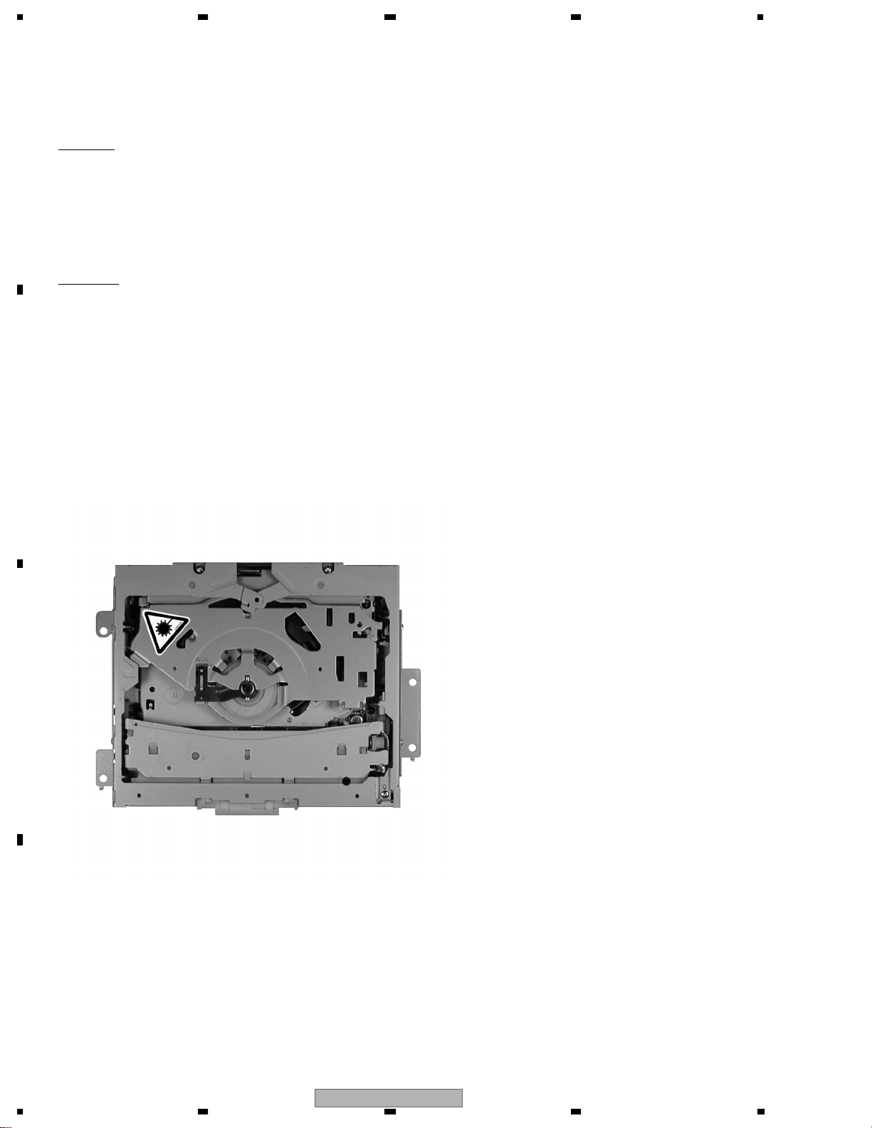
2. The triangular label is attached to the mechanism
unit frame.
C
D
2
1234
DVH-P7000R
A
B
5678
CLASS 1
LASER PRODUCT
On the top of the player.
CAUTION :
VORSICHT :
ADVARSEL :
VARNING :
VARO! :
VISIBLE AND INVISIBLE LASER RADIATION WHEN OPEN.
AVOID EXPOSURE TO BEAM.
SICHTBARE UND UNSICHTBARE LASERSTRAHLUNG, WENN
ABDECKUNG GEÖFFNET NICHT DEM STRAHL AUSSETZEN!
SYNLIG OG USYNLIG LASERSTRÅLING VED ÅBNING
UNDGÅ UDSÆTTELSE FOR STRÀLING.
SYNLIG OCH OSYNLIG LASERSTRÅLNING NÄR DENNA
DEL ÄR ÖPPNAD BETRAKTA EJ STRÅLEN.
AVATTAESSA ALTISTUT NÄKYVÄ JA NÄKYMÄTTÖMÄLLE
LASERSATEIL YLLE. ÄLÄ KATSO SÄTEESEN.
VRW1860
WARNING!
The AEL (accessible emission level )of the laser power output is less than CLASS 1
but the laser component is capable of emitting radiation exceeding the limit for
CLASS 1.
A specially instructed person should do servicing operation of the apparatus.
Laser diode characteristics
Wave length:
DVD:640~660nm
CD:770~810nm
Maximum output:2.44mw(Emitting period :9sec.)
DVD:743mw(Emitting period : unlimited)
Additionla Laser Caution
C
Transistors Q1104 and Q1108 in PCB drive the laser diodes for DVD and CD
respectively. When Q1104 or Q1108 is shorted between their terminals,
the laser diodes for DVD or CD will radiate beam. If the top cover is removed
with no disc loaded while such short-circuit is continued, the naked eyes may
be exposed to the laser beam.
CAUTION
Danger of explosion if battery is incorrectly replaced.
Replaced only with the same or equivalent type recommended by the manufacture.
Discord used batteries according to the manufacture's instructions.
DVH-P7000R
56
7
D
3
8
1234
--
--
Manufactured under license from Dolby Laboratories. "Dolby" and the double-D sym-
bol are trademarks of Dolby Laboratories.
--
--
DVD Player Service Precautions
1. Never adjust the LD VR in the pickup unit to protect the pickup from electrical damages.
2. For pickup unit(service)(CXX1530) handling, please refer to"Disassembly"(see page
A
124). During replacement, handling precautions shall be taken to prevent an electrostatic
discharge(set the short switch of the pickup unit to the SHORT side).
3. During disassembly, be sure to turn the power off since an internal IC might be
destroyed when a connector is plugged or unplugged.
4. Please adjusting the skew after changing the pickup unit(see page 106).
[ Important symbols for good services ]
In this manual, the symbols shown-below indicate that adjustments, settings or cleaning should be made securely.
When you find the procedures bearing any of the symbols, be sure to fulfill them:
1. Product safety
You should conform to the regulations governing the product (safety, radio and noise, and other regulations), and
should keep the safety during servicing by following the safety instructions described in this manual.
2. Adjustments
B
To keep the original performances of the product, optimum adjustments or specification confirmation is indispensable.
In accordance with the procedures or instructions described in this manual, adjustments should be performed.
3. Cleaning
For optical pickups, tape-deck heads, lenses and mirrors used in projection monitors, and other parts requiring cleaning,
proper cleaning should be performed to restore their performances.
4. Shipping mode and shipping screws
To protect the product from damages or failures that may be caused during transit, the shipping mode should be set or
the shipping screws should be installed before shipping out in accordance with this manual, if necessary.
5. Lubricants, glues, and replacement parts
C
Appropriately applying grease or glue can maintain the product performances. But improper lubrication or applying
glue may lead to failures or troubles in the product. By following the instructions in this manual, be sure to apply the
prescribed grease or glue to proper portions by the appropriate amount.For replacement parts or tools, the prescribed
ones should be used.
D
4
1234
DVH-P7000R

A
B
5678
CONTENTS
SAFETY INFORMATION. . . . . . . . . . . . . . . . . . . . . . . . . . . . . . . . . . . . . 2
1. SPECIFICATIONS . . . . . . . . . . . . . . . . . . . . . . . . . . . . . . . . . . . . . . . 6
2. EXPLODED VIEWS AND PARTS LIST . . . . . . . . . . . . . . . . . . . . . . . . . . . .10
2.1 PACKING(DVH-P7000R/EW) . . . . . . . . . . . . . . . . . . . . . . . . . . . . . . .10
2.2 PACKING(DVH-P7000/UC) . . . . . . . . . . . . . . . . . . . . . . . . . . . . . . . .12
2.3 PACKING(DVH-P7050/ES/RC,DVH-P7050/ES/RD). . . . . . . . . . . . . . . . . . . .14
2.4 EXTERIOR(1)(DVH-P7000R/EW). . . . . . . . . . . . . . . . . . . . . . . . . . . . .16
2.5 EXTERIOR(1)(DVH-P7000/UC,DVH-P7050/ES/RC,DVH-P7050/ES/RD). . . . . . . . .18
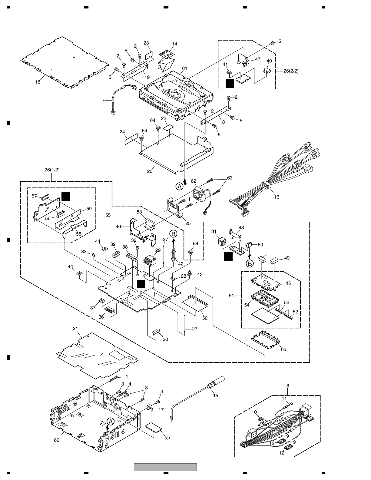
2.6 EXTERIOR(2)(DVH-P7000R/EW). . . . . . . . . . . . . . . . . . . . . . . . . . . . .20
2.7 EXTERIOR(2)(DVH-P7000/UC,DVH-P7050/ES/RC,DVH-P7050/ES/RD). . . . . . . . .22
2.8 DVD Mechanism Module . . . . . . . . . . . . . . . . . . . . . . . . . . . . . . . . .24
3. BLOCK DIAGRAM AND SCHEMATIC DIAGRAM . . . . . . . . . . . . . . . . . . . . . . .26
3.1 BLOCK DIAGRAM(1) . . . . . . . . . . . . . . . . . . . . . . . . . . . . . . . . . . .26
3.2 BLOCK DIAGRAM(2)(DVH-P7000R/EW) . . . . . . . . . . . . . . . . . . . . . . . . .28
3.3 BLOCK DIAGRAM(2)(DVH-P7000/UC,DVH-P7050/ES/RC,DVH-P7050/ES,RD). . . . .30
3.4 OVERALL CONNECTION DIAGRAM(GUIDE PAGE)(EW) . . . . . . . . . . . . . . . .32
3.5 OVERALL CONNECTION DIAGRAM(GUIDE PAGE)(UC,ES/RC,ES/RD) . . . . . . . .38
3.6 KEYBOARD UNIT(EW) . . . . . . . . . . . . . . . . . . . . . . . . . . . . . . . . . .44
3.7 KEYBOARD UNIT(UC,ES/RC,ES/RD) . . . . . . . . . . . . . . . . . . . . . . . . . .46
3.8 POWER SUPPLY UNIT . . . . . . . . . . . . . . . . . . . . . . . . . . . . . . . . . .48
3.9 EXTENSION PCB . . . . . . . . . . . . . . . . . . . . . . . . . . . . . . . . . . . . .50
3.10 OPTICAL PCB . . . . . . . . . . . . . . . . . . . . . . . . . . . . . . . . . . . . . .51
3.11 DVD MECHANISM MODULE(1/2)(GUIDE PAGE) . . . . . . . . . . . . . . . . . . . .52
3.12 DVD MECHANISM MODULE(2/2)(GUIDE PAGE) . . . . . . . . . . . . . . . . . . . .58
3.13 PU UNIT(REFERENCE) . . . . . . . . . . . . . . . . . . . . . . . . . . . . . . . . .66
4. PCB CONNECTION DIAGRAM . . . . . . . . . . . . . . . . . . . . . . . . . . . . . . . .68
4.1 MOTHER PCB. . . . . . . . . . . . . . . . . . . . . . . . . . . . . . . . . . . . . . .68
4.2 PANEL UNIT. . . . . . . . . . . . . . . . . . . . . . . . . . . . . . . . . . . . . . . .72
4.3 KEYBOARD UNIT . . . . . . . . . . . . . . . . . . . . . . . . . . . . . . . . . . . . .73
4.4 EXTENSION PCB, OPTICAL PCB . . . . . . . . . . . . . . . . . . . . . . . . . . . .74
4.5 POWER SUPPLY UNIT . . . . . . . . . . . . . . . . . . . . . . . . . . . . . . . . . .76
4.6 DVD CORE UNIT V . . . . . . . . . . . . . . . . . . . . . . . . . . . . . . . . . . . .78
5. ELECTRICAL PARTS LIST . . . . . . . . . . . . . . . . . . . . . . . . . . . . . . . . . .82
6. ADJUSTMENT. . . . . . . . . . . . . . . . . . . . . . . . . . . . . . . . . . . . . . . . 102
6.1 OEL ADJUSTMENT . . . . . . . . . . . . . . . . . . . . . . . . . . . . . . . . . . . 102
6.2 DVD ADJUSTMENT. . . . . . . . . . . . . . . . . . . . . . . . . . . . . . . . . . . 103
7. GENERAL INFORMATION . . . . . . . . . . . . . . . . . . . . . . . . . . . . . . . . . 124
7.1 DIAGNOSIS . . . . . . . . . . . . . . . . . . . . . . . . . . . . . . . . . . . . . . . 124
7.1.1 DISASSEMBLY . . . . . . . . . . . . . . . . . . . . . . . . . . . . . . . . . . . . 124
7.1.2 CONNECTOR FUNCTION DESCRIPTION . . . . . . . . . . . . . . . . . . . . . . 128
7.2 IC . . . . . . . . . . . . . . . . . . . . . . . . . . . . . . . . . . . . . . . . . . . . 129
7.3 OPERATIONAL FLOW CHART . . . . . . . . . . . . . . . . . . . . . . . . . . . . . 154
7.4 CLEANING . . . . . . . . . . . . . . . . . . . . . . . . . . . . . . . . . . . . . . . 156
8. OPERATIONS . . . . . . . . . . . . . . . . . . . . . . . . . . . . . . . . . . . . . . . . 157
C
DVH-P7000R
56
D
7
5
8

1234
1. SPECIFICATIONS
- DVH-P7000R/EW
General
Power source ............... 14.4 V DC
A
B
C
Grounding system ...... Negative type
Max. current consumption
..................................... 10.0 A
Backup current
..................................... 5 mA or less
Dimensions (W × H × D):
Chassis (DIN) ......... 178 × 50 × 161 mm
Nose ................ 188 × 58 × 22 mm
Weight ......................... 1.6 kg
Audio
Maximum power output 50W × 4
for subwoofer (70 W ×1 ch/2 Ω)
Continuous power output 27W × 4
Load impedance ..........4Ω(4 –8 Ω[2 Ω for 1
Preout max output level/output impedance
..................................... 4.0 V/1 kΩ
Equalizer (3-Band Parametric Equalizer):
(Low)
Frequency ....... 40/80/100/160 Hz
Q Factor .......... 0.35/0.59/0.95/1.15
Gain ................
(Mid)
Frequency ....... 200/500/1k/2kHz
Q Factor .......... 0.35/0.59/0.95/1.15
Gain ................
(High)
Frequency ....... 3.15k/8k/10k/12.5kHz
Q Factor .......... 0.35/0.59/0.95/1.15
Gain ................
Loudness contour:
(Low) ..................... +3.5 dB (100 Hz)
(Mid) ..................... +10 dB (100 Hz)
(High) .................... +11 dB (100 Hz)
Tone controls:
(Bass)
Frequency ....... 40/63/100/160 Hz
Gain ................
(Treble)
Frequency ....... 2.5 k/4k/6.3k/10kHz
Gain ................ ±12 dB
HPF:
Frequency ....... 50/80/125 Hz
Slope ............... –12 dB/oct
Subwoofer:
Frequency ....... 50/80/125 Hz
Slope ............... –18 dB/oct
Gain ................ ±12 dB
Phase ............... Normal/Reverse
(10.8 –15.1 V allowable)
25W × 4 (BRI)
(DIN 45324, +B=14.4 V)
ch]allowable)
(+6 dB when boosted)
±12 dB
(+6 dB when boosted)
±12 dB
(+6 dB when boosted)
±12 dB
+3 dB (10 kHz)
+6.5 dB (10 kHz)
+11 dB (10 kHz)
(Volume: –30 dB)
±12 dB
DVD player
System ......................... DVD-Video, Video CD,
Region Number
Usable discs ................. DVD-Video, Video CD,
Signal format:
Sampling frequency 44.1/48/96 kHz
Number of
quantization bits .. 16/20/24;linear
Frequency response ...5–44,000 Hz
Signal-to-noise ratio ... 97 dB (1kHz)
Dynamic range ............ 96 dB (1 kHz)
Distortion .................... 0.008 %(1 kHz)
Output level:
Video ..................... 1.0 Vp-p/75 Ω(±0.2V)
Audio .................... 1.0V(1 kHz, 0 dB)
Number of channels ...2 (stereo)
.....
Compact disc audio
system
............2
Compact disc
(with DVD, at
Sampling
frequncy 96 kHz)
(IEC-A network)
(CD: 96dB(1kHz)
(IEC-A network)
(CD: 95 dB (1 kHz))
FM tuner
Frequency range ......... 87.5 –108 MHz
Usable sensitivity ........ 10 dBf (0.9 µV/75 Ω,
50 dB quieting sensitivity 15 dBf (1.5 µV/75 Ω, mono)
Signal-to-noise ratio ... 70 dB (IEC-A network)
Distortion .................... 0.3% (at 65 dBf, 1kHz,stereo)
Frequency response ... 30 –15,000 Hz (±3dB)
Stereo separation ........ 40 dB (at 65 dBf, 1kHz)
mono, S/N:30 dB)
MW tuner
Frequency range ......... 531 –1,602 kHz (9kHz)
Usable sensitivity ........ 18 µV (S/N: 20 dB)
Selectivity .................... 50 dB (±9 kHz)
LW tuner
Frequency range ......... 153 –281 kHz
Usable sensitivity ........ 30 µV (S/N: 20 dB)
Selectivity .................... 50 dB (±9 kHz)
Note
• Specifications and the design are subject to possible modifications without
notice due to improvements.
D
6
DVH-P7000R
1234

A
B
5678
- DVH-P7000/UC
General
Power source ............... 14.4 V DC
Grounding system ...... Negative type
Max. current consumption
..................................... 10.0 A
Backup current
..................................... 5 mA or less
Dimensions (W × H × D)
(DIN) ...................... Chassis 178 × 50 × 161 mm
Nose .............. 188 × 5 × 8 × 22 mm
(D) Chassis ........ 178 × 50 × 166 mm
Nose .............. 170 × 46 × 17 mm
Weight ......................... 1.6 kg (3.5 lbs.)
Audio
Continuous power output is 22 W per
channnel min. into 4 ohms, both channels
driven 50 to 15,000 Hz with no more than 5%
THD.
Maximum power output 50W × 4
Load impedance ..........4Ω(4 –8 Ω[2 Ω for 1ch]allowable)
Preout max output level/output impedance
..................................... 4.0 V/1 kΩ
Equalizer (3-Band Parametric Equalizer):
(Low)
Frequency ....... 40/80/100/160 Hz
Q Factor .......... 0.35/0.59/0.95/1.15
Gain ................
(Mid)
Frequency ....... 200/500/1k/2kHz
Q Factor .......... 0.35/0.59/0.95/1.15
Gain ................
(High)
Frequency ....... 3.15k/8k/10k/12.5kHz
Q Factor .......... 0.35/0.59/0.95/1.15
Gain ................
Loudness contour:
(Low) ..................... +3.5 dB (100 Hz)
(Mid) ..................... +10 dB (100 Hz)
(High) .................... +11 dB (100 Hz)
Tone controls:
(Bass)
Frequency ....... 40/63/100/160 Hz
Gain ................
(Treble)
Frequency ....... 2.5 k/4k/6.3k/10kHz
Gain ................ ±12 dB
HPF:
Frequency ....... 50/80/125 Hz
Slope ............... –12 dB/oct
Subwoofer:
Frequency ....... 50/80/125 Hz
Slope ............... –18 dB/oct
Gain ................ ±12 dB
Phase ............... Normal/Reverse
(10.8 –15.1 V allow-
able)
[7 × 26-3/8 in]
[7-3/8 × 2-1/4 × 7/8 in]
[7 × 2 × 6-1/2 in]
[6-3/4 × 1-3/4 × 5/8in]
for subwoofer (70 W ×1 ch/2 Ω)
(+6 dB when boosted)
±12 dB
(+6 dB when boosted)
±12 dB
(+6 dB when boosted)
±12 dB
+3 dB (10 kHz)
+6.5 dB (10 kHz)
+11 dB (10 kHz)
(Volume: –30 dB)
±12 dB
DVD player
System ......................... DVD-Video, Video CD,
Region Number : 1
Usable discs ................. DVD-Video, Video CD,
Signal format:
Sampling frequency 44.1/48/96 kHz
Number of
quantization bits .. 16/20/24;linear
Frequency response ...5–44,000 Hz
Signal-to-noise ratio ... 97 dB (1kHz)
Dynamic range ............ 96 dB (1 kHz)
Distortion .................... 0.008 %(1 kHz)
Output level:
Video ..................... 1.0 Vp-p/75 Ω(±0.2 V)
Audio .................... 1.0V(1 kHz, 0 dB)
Number of channels ...2 (stereo)
FM tuner
Frequency range ......... 87.9 –107.9 MHz
Usable sensitivity ........ 10 dBf (0.9 µV/75 Ω,
50 dB quieting sensitivity 15 dBf (1.5 µV/75 Ω,mono)
Signal-to-noise ratio ... 70 dB (IEC-A network)
Distortion .................... 0.3% (at 65 dBf, 1kHz, stereo)
Frequency response ... 30 –15,000 Hz (±3 dB)
Stereo separation ........ 40 dB (at 65 dBf, 1 kHz)
Selectivity .................... 70 dB
Three signal intermodulation
(Desire signal level) 30 dBf
(two undesire signal level: 100 dBf)
Compact disc audio
system
..........
Compact disc
(with DVD, at
Sampling
frequncy 96 kHz)
(IEC-A network)
(CD: 96dB(1kHz)
(IEC-A network))
(CD: 95 dB (1 kHz))
mono, S/N:30 dB)
AM tuner
Frequency range ......... 530 –1,710 kHz (10 kHz)
Usable sensitivity ........ 18 µV (S/N: 20 dB)
Selectivity .................... 50 dB (±10 kHz)
50 dB (±9 kHz)
Note
• Specifications and the design are subject to possible modifications without
notice due to improvements.
C
D
DVH-P7000R
56
7
8
7

1234
- DVH-P7050/ES/RC, DVH-P7050/ES/RD
General
Power source ............... 14.4 V DC
Grounding system ...... Negative type
A
Max. current consumption
..................................... 10.0 A
Backup current
..................................... 5 mA or less
Dimensions (W × H × D):
(DIN) Chassis ......... 178 × 50 × 161 mm
Nose ................ 188 × 58 × 22 mm
(D) Chassis ............ 178 × 50 × 166 mm
Nose ................ 170 × 46 × 17 mm
Weight ......................... 1.6 kg
Audio
Continuous power output is 22 W per
channnel min. into 4 ohms, both channels
driven 50 to 15,000 Hz with no more than 5%
THD.
Maximum power output 50W × 4
Load impedance ..........4Ω(4 –8 Ω[2 Ω for 1
Preout max output level/output impedance
..................................... 4.0 V/1 kΩ
B
Equalizer (3-Band Parametric Equalizer):
(Low)
(Mid)
(High)
Loudness contour:
(Low) ..................... +3.5 dB (100 Hz)
(Mid) ..................... +10 dB (100 Hz)
(High) .................... +11 dB (100 Hz)
for subwoofer (70 W ×1 ch/2 Ω)
Frequency ....... 40/80/100/160 Hz
Q Factor .......... 0.35/0.59/0.95/1.15
Gain ................
Frequency ....... 200/500/1k/2kHz
Q Factor .......... 0.35/0.59/0.95/1.15
Gain ................
Frequency ....... 3.15k/8k/10k/12.5kHz
Q Factor .......... 0.35/0.59/0.95/1.15
Gain ................
C
Tone controls:
(Bass)
Frequency ....... 40/63/100/160 Hz
Gain ................
(Treble)
Frequency ....... 2.5 k/4k/6.3k/10kHz
(10.8 –15.1 V allowable)
ch]allowable)
(+6 dB when boosted)
±12 dB
(+6 dB when boosted)
±12 dB
(+6 dB when boosted)
±12 dB
+3 dB (10 kHz)
+6.5 dB (10 kHz)
+11 dB (10 kHz)
(Volume: –30 dB)
±12 dB
DVD player
System ......................... DVD-Video, Video CD,
Region Number
for Southeast Asian models : 3
for South American and Oceanian models : 4
Usable discs ................. DVD-Video, Video CD,
Signal format:
Sampling frequency 44.1/48/96 kHz
Number of
quantization bits .. 16/20/24;linear
Frequency response ...5–44,000 Hz
Signal-to-noise ratio ... 97 dB (1kHz)
Dynamic range ............ 96 dB (1 kHz)
Distortion .................... 0.008 %(1 kHz)
Output level:
Video ..................... 1.0 Vp-p/75 Ω(±0.2V)
Audio .................... 1.0V(1 kHz, 0 dB)
Number of channels ...2 (stereo)
Compact disc audio
system
Compact disc
(with DVD, at
Sampling
frequncy 96 kHz)
(IEC-A network)
(CD: 96dB(1kHz)
(IEC-A network))
(CD: 95 dB (1 kHz))
FM tuner
Frequency range ......... 87.5 –108 MHz
Usable sensitivity ........ 10 dBf (0.9 µV/75 Ω,
50 dB quieting sensitivity 15 dBf (1.5 µV/75 Ω,mono)
Signal-to-noise ratio ... 70 dB (IEC-A network)
Distortion .................... 0.3% (at 65 dBf, 1kHz,stereo)
Frequency response ... 30 –15,000 Hz (±3dB)
Stereo separation ........ 40 dB (at 65 dBf, 1kHz)
mono, S/N:30 dB)
AM tuner
Frequency range ......... 530 –1,640 kHz (10kHz)
Usable sensitivity ........ 18 µV (S/N: 20 dB)
Selectivity .................... 50 dB (±10 kHz)
531 –1,602 kHz (9kHz)
50 dB (±9 kHz)
Infrared Remote Control
Wavelength ................. 940 nm ±50 nm
Output ......................... typ; 12 mw/sr per
Infrared LED
Note
• Specifications and the design are subject to possible modifications without
notice due to improvements.
Gain ................ ±12 dB
HPF:
Frequency ....... 50/80/125 Hz
Slope ............... –12 dB/oct
Subwoofer:
Frequency ....... 50/80/125 Hz
Slope ............... –18 dB/oct
Gain ................ ±12 dB
Phase ............... Normal/Reverse
D
8
DVH-P7000R
1234

A
B
9
5678
C
DVH-P7000R
56
D
7
8
1234
2. EXPLODED VIEWS AND PARTS LIST
NOTES : • Parts marked by " * " are generally unavailable because they are not in our Master Spare Parts List.
• Screw adjacent to mark on the product are used for disassembly.
• For the applying amount of lobricants or glue, follow the instructions in this manual.
A
(In the case of no amount instructions,apply as you think it appropriate.)
"
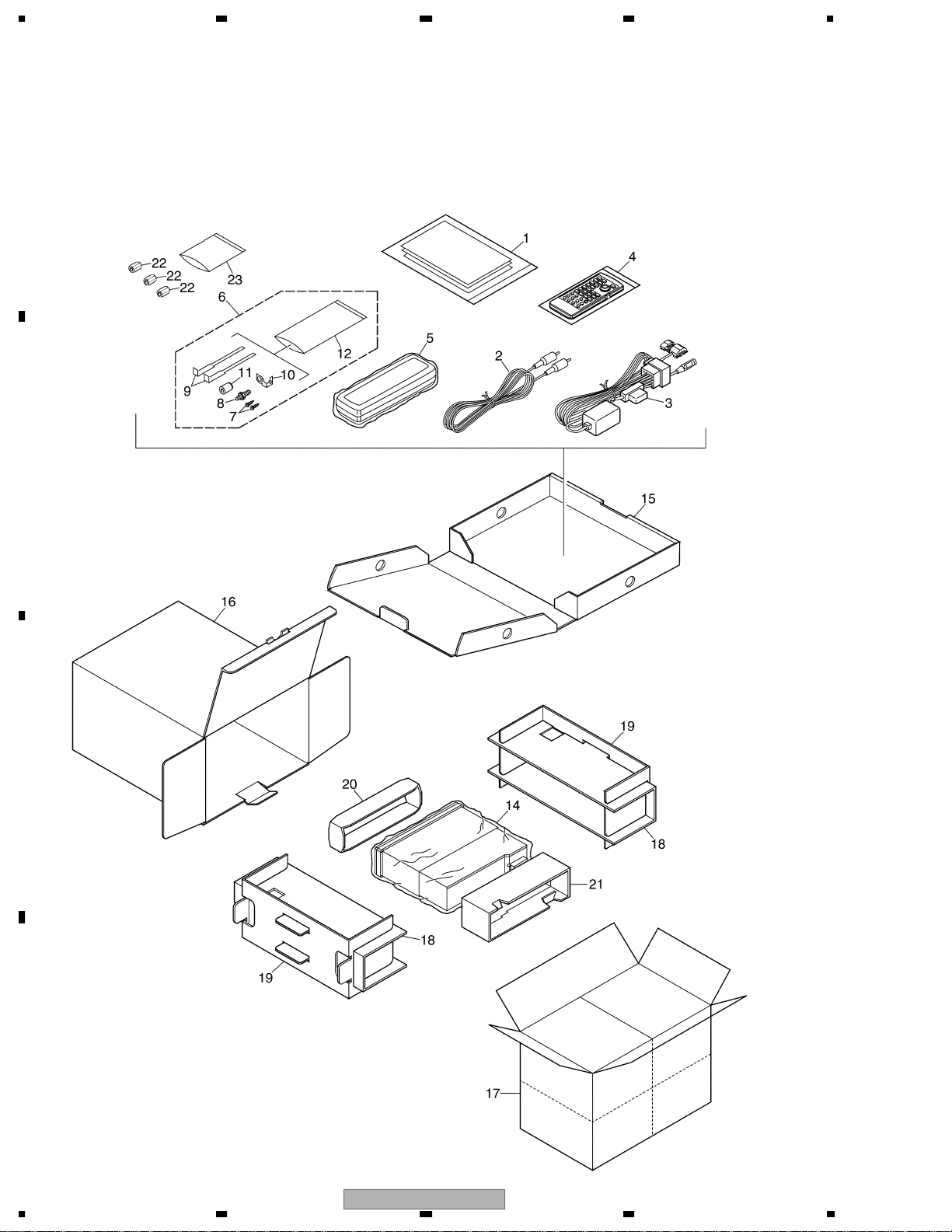
2.1 PACKING(DVH-P7000R/EW)
B
C
D
10
1234
DVH-P7000R
A
B
5678
PACKING(DVH-P7000R/EW) SECTION PARTS LIST
Mark
No. Description Part No.
1-1 Polyethylene Bag CEG1116
1-2 Owner’s Manual CRD3606
1-3 Owner’s Manual CRD3607
1-4 Owner’s Manual CRD3608
1-5 Installation Manual CRD3609
* 1-6 Caution Card CRP1207
1-7 Passport CRY1013
* 1-8 Warranty Card CRY1157
1-9 Caution Card CRP1278
2 Cord Assy CDE6376
3 Cord Assy CDE6760
4 Remote Control Unit CXB8827
5 Case Assy CXB3520
6 Accessory Assy CEA3329
7 Screw BPZ20P060FZK
8 Screw CBA1284
9 Handle CNC5395
10 Earth Plate CNC9450
11 Bush CNV1009
* 12 Polyethylene Bag E36-615
13 •••••
* 14 Polyethylene Bag CEG1305
15 Sub Carton CHA3167
16 Carton CHG4694
17 Contain Box CHL4694
18 Protector CHP2383
19 Protector CHP2384
20 Protector CHP2385
21 Protector CHP2386
22 Filter CTX1060
* 23 Polyethylene Bag CEG-158
C
Owner's Manual,Installation Manual
Part No. Language
CRD3606 English, Spanish
CRD3607 German, French
CRD3608 Italian, Dutch
CRD3609 English, Spanish, German, French, Italian, Dutch
56
DVH-P7000R
D
11
7
8
1234
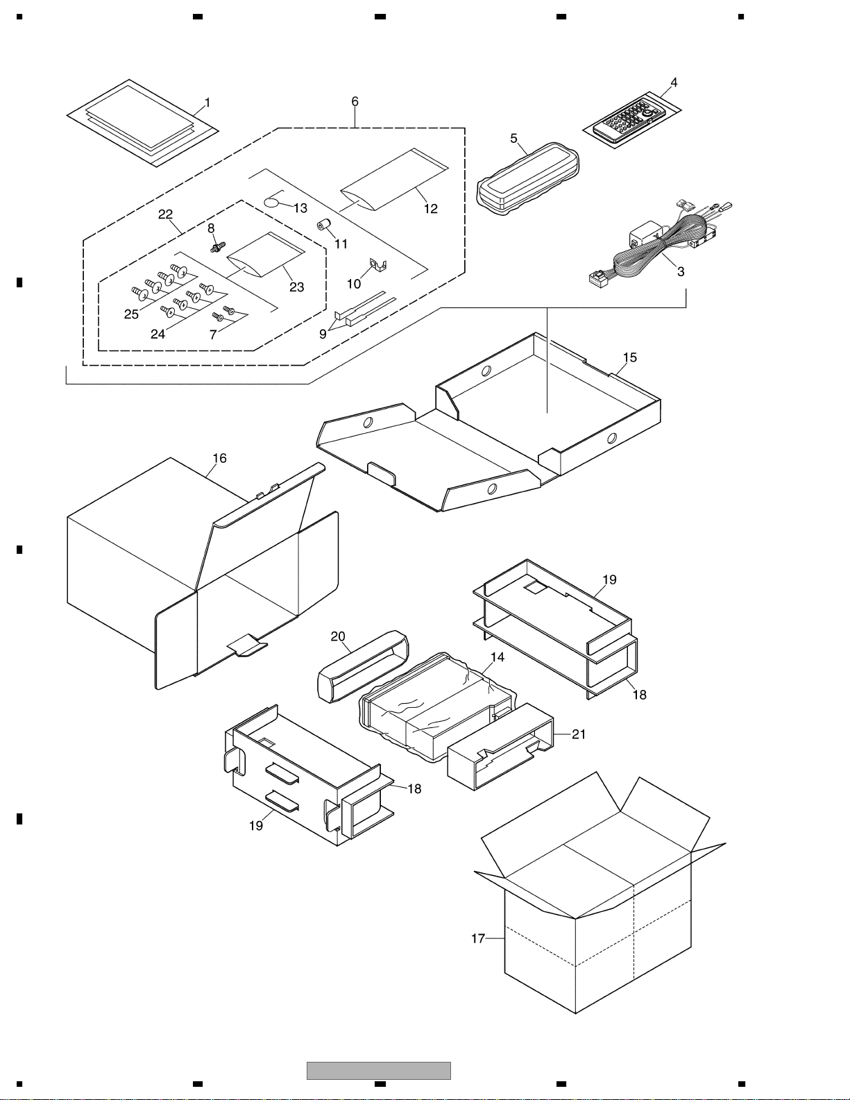
2.2 PACKING(DVH-P7000/UC)
A
B
C
D
12
1234
DVH-P7000R
A
B
5678
PACKING(DVH-P7000/UC) SECTION PARTS LIST
Mark
No. Description Part No.
1-1 Polyethylene Bag CEG1116
1-2 Owner’s Manual CRD3610
1-3 Installation Manual CRD3611
* 1-4 Card ARY1048
* 1-5 Caution Card CRP1207
3 Cord Assy CDE6761
4 Remote Control Unit CXB8827
5 Case Assy CXB3520
6 Accessory Assy CEA3330
7 Screw BPZ20P060FZK
8 Screw CBA1284
9 Handle CNC5395
10 Earth Plate CNC9450
11 Bush CNV1009
* 12 Polyethylene Bag CEG-158
13 Spring CBH-865
14 Polyethylene Bag CEG1185
15 Sub Carton CHA3167
16 Carton CHG4695
17 Contain Box CHL4695
18 Protector CHP2383
19 Protector CHP2384
20 Protector CHP2385
21 Protector CHP2386
22 Screw Assy CEA3100
* 23 Polyethylene Bag CEG-127
24 Screw CRZ50P090FMC
25 Screw TRZ50P080FMC
Owner's Manual,Installation Manual
Part No. Language
CRD3610 English, French
CRD3611 English, French
C
D
DVH-P7000R
56
7
8
13

1234
2.3 PACKING(DVH-P7050/ES/RC,DVH-P7050/ES/RD)
A
B
C
D
14
1234
DVH-P7000R
A
B
5678
(1)PACKING(DVH-P7050/ES/RC,DVH-P7050/ES/RD) SECTION PARTS LIST
Mark
No. Description Part No.
1-1 Polyethylene Bag CEG1116
1-2 Owner’s Manual CRB1759
1-3 Owner’s Manual See Contrast table(2)
* 1-4 Caution Card CRP1207
2 Cord CDE6765
3 Cord Assy CDE6761
4 Remote Control Unit CXB8827
5 Case Assy CXB3520
6 Accessory Assy CEA2002
7 •••••
8 Screw CBA1284
9 Handle CNC5395
10 •••••
11 Bush CNV1009
* 12 Polyethylene Bag CEG-158
13 Spring CBH865
* 14 Polyethylene Bag CEG1305
15 Sub Carton CHA3167
16 Carton See Contrast table(2)
17 Contain Box See Contrast table(2)
18 Protector CHP2383
19 Protector CHP2384
20 Protector CHP2385
21 Protector CHP2386
22 Screw Assy CEA200331
* 23 Polyethylene Bag CEG-127
24 Screw CRZ50P090FMC
25 Screw TRZ50P080FMC
(2) CONTRAST TABLE
DVH-P7050/ES/RC and DVH-P7050/ES/RD are constructed the same except for the following:
k NO Symbol and Description DVH-P7050/ES/RC DVH-P7050/ES/RD
Mar
1-3 Owner’s Manual CRB1760 CRB1761
16 Carton CHG4692 CHG4693
17 Contain Box CHL4692 CHL4693
Owner's Manual
Part No. Language
CRB1759 English
CRB1760 Traditional Chinese
CRB1761 Spanish
C
D
DVH-P7000R
56
7
8
15
1234
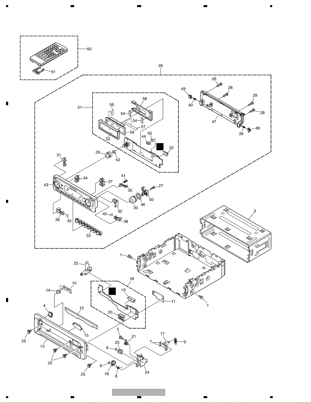
2.4 EXTERIOR(1)(DVH-P7000R/EW)
A
B
C
B
C
D
16
1234
DVH-P7000R

A
B
5678
EXTERIOR(1)(DVH-P7000R/EW) SECTION PARTS LIST
Mark
No. Description Part No.
1 Screw BMZ30P040FZK
2 •••••
3 Holder CNC8659
4 Button(EJECT) CAC6839
5 Screw(M2x2) CBA1176
6 Washer CBF1038
7 Washer CBF1039
8 Spring CBH2428
9 Spring CBH2429
10 Spring CBL1512
11 Holder CNC9096
12 Cover CNM6854
13 Panel CNS6930
14 Pin CNV6486
15 Lighting Conductor CNV6487
16 Gear CNV6507
17 Arm CNV6508
18 Panel Unit CWM7986
19 Socket(CN1850) CKS3550
20 Connector(CN1851) CKS4462
21 Damper Unit CXB5070
22 Holder Unit CXB6357
23 Clutch Unit CXB6358
24 Holder Unit CXB7506
25 Screw IMS20P045FZK
26 Detach Grille Assy CXB8437
27 Screw BPZ20P080FMC
28 Screw BPZ20P100FZK
29 Knob CAA2750
30 Button(SELECT) CAC7220
31 Button(TA) CAC7223
32 Button(AUDIO) CAC7224
33 Button(1-6) CAC7225
34 Button(DISP) CAC7226
35 Button(OPEN) CAC7227
36 Button(EQ) CAC7231
37 Button(FUNC) CAC7489
38 Button(SFEQ) CAC7490
39 Spring CBH2430
40 Spring CBH2431
41 Spring CBH2630
42 Spring CBL1470
43 Sub Grille Assy CXB9129
44 IC(IC1903) TSOP1840SB3V
45 Spacer CNM7807
46 Cushion CNM7808
47 Cover CNS6740
48 Holder CNV6505
49 Holder CNV6506
50 Holder CNV6909
DVH-P7000R
56
No. Description Part No.
Mark
51 Keyboard Unit CWM8158
52 Connector(CN1901) CKS4524
53 Holder CNC9642
54 Cushion CNM6633
55 Cushion CNM7469
56 Spacer CNM7697
57 Spacer CNM7698
58 Holder CNV6910
59 OEL Unit MXS8017
60 Remote Control Unit CXB8827
61 Cover CZN5357
7
C
D
17
8
1234
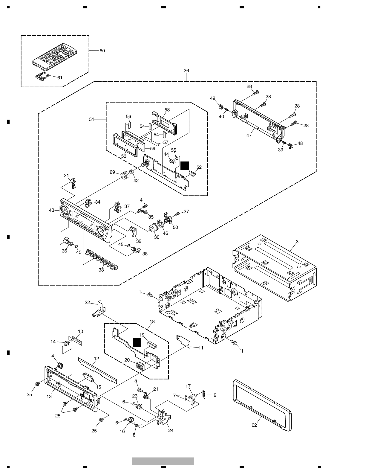
2.5 EXTERIOR(1)(DVH-P7000/UC,DVH-P7050/ES/RC,DVH-P7050/ES/RD)
A
C
B
C
B
D
18
1234
DVH-P7000R
A
B
5678
(1)EXTERIOR(1)(DVH-P7000/UC,DVH-P7050/ES/RC,DVH-P7050/ES/RD) SECTION PARTS LIST
No. Description Part No.
Mark
No. Description Part No.
1 Screw BMZ30P040FZK
2 •••••
3 Holder CNC8659
4 Button(EJECT) CAC6839
5 Screw(M2x2) CBA1176
6 Washer CBF1038
7 Washer CBF1039
8 Spring CBH2428
9 Spring CBH2429
10 Spring CBL1512
11 Holder CNC9096
12 Cover CNM6854
13 Panel CNS6278
14 Pin CNV6486
15 Lighting Conductor CNV6487
16 Gear CNV6507
17 Arm CNV6508
18 Panel Unit CWM7986
19 Socket(CN1850) CKS3550
20 Connector(CN1851) CKS4462
21 Damper Unit CXB5070
22 Holder Unit CXB6357
23 Clutch Unit CXB6358
24 Holder Unit CXB7506
25 Screw IMS20P045FZK
26 Detach Grille Assy See Contrast table(2)
27 Screw BPZ20P080FMC
28 Screw BPZ20P100FZK
29 Knob CAA2750
30 Button(SELECT) CAC7220
31 Button(ENT) See Contrast table(2)
32 Button(AUDIO) See Contrast table(2)
33 Button(1-6) CAC7225
34 Button(DISP) CAC7226
35 Button(OPEN) CAC7227
Mark
36 Button(EQ) CAC7231
37 Button(FUNC) CAC7489
38 Button(SFEQ) CAC7490
39 Spring CBH2430
40 Spring CBH2431
41 Spring CBH2630
42 Spring CBL1470
43 Sub Grille Assy See Contrast table(2)
44 IC(IC1903) TSOP1840SB3V
45 Spacer CNM7807
46 Cushion CNM7808
47 Cover CNS6740
48 Holder CNV6505
49 Holder CNV6506
50 Holder CNV6909
51 Keyboard Unit CWM8157
52 Connector(CN1901) CKS4524
53 Holder CNC9642
54 Cushion CNM6633
55 Cushion CNM7469
56 Spacer CNM7697
57 Spacer CNM7698
58 Holder CNV6910
59 OEL Unit MXS8017
60 Remote Control Unit CXB8827
61 Cover CZN5357
62 Panel See Contrast table(2)
C
(2) CONTRAST TABLE
DVH-P7000/UC, DVH-P7050/ES/RC and DVH-P7050/ES/RD are constructed the same except for the following:
Mar
k NO Symbol and Description DVH-P7000/UC DVH-P7050/ES/RC DVH-P7050/ES/RD
26 Detach Grille Assy CXB8438 CXB8439 CXB8440
31 Button(ENT) CAC7303 CAC7253 CAC7253
32 Button(AUDIO) CAC7224 CAC7254 CAC7254
43 Sub Grille Assy CXB9130 CXB9128 CXB9128
62 Panel CNS6934 CNS6935 CNS6935
DVH-P7000R
56
7
19
8
D
1234
2.6 EXTERIOR(2)(DVH-P7000R/EW)
A
D
B
F
E
49
A
C
D
20
1234
DVH-P7000R

A
B
5678
EXTERIOR(2)(DVH-P7000R/EW) SECTION PARTS LIST
Mark
No. Description Part No.
1 Screw BMZ26P120FMC
2 Screw BSZ26P060FMC
3 Screw BSZ30P060FMC
4 Screw BSZ30P200FMC
5 Screw(M2x2.2) CBA1419
6 •••••
7 Cord CDE6574
8 Cord Assy CDE6760
9 Resistor RS1/2PMF102J
10 Fuse(10A) CEK1136
11 Cap CKX-003
12 Cap CNS1472
13 Cord Assy CDE6762
14 Cable CDE6766
15 Cord CDH1208
16 Case CNB2732
17 Holder CNC4963
18 Holder CNC9793
19 Holder CNC9794
20 Holder CND1196
21 Insulator CNM7632
22 Spacer CNM7634
23 Sheet CNM7834
24 Sheet CNM7835
25 Heat Sink CNR1617
26 Tuner Amp Unit CWM8152
27 Clamper CEF1009
28 Terminal(CN401) CKF1059
29 Plug(CN802) CKM1370
30 Plug(CN171) CKS1043
31 Connector(CN1602) CKS2104
32 Connector(CN801) CKS3124
33 Connector(CN971) CKS3124
34 •••••
35 •••••
36 Plug(CN101) CKS3537
37 Connector(CN202) CKS3598
38 Connector(CN301) CKS3606
39 Connector(CN201) CKS3661
40 Connector(CN1702) CKS3902
41 Connector(CN1701) CKS4496
42 Connector(CN972) CKS4581
43 Mini Pin Jack(CN402) CKX1046
44 Holder CNC5399
45 Case CNC8709
46 Holder CNC9788
47 Holder CNC9791
48 Holder CNC9792
49 Cushion CNM6870
50 Insulator CNM7640
DVH-P7000R
56
No. Description Part No.
Mark
51 FM/AM Tuner Unit CWE1607
52 Connector(CN1,2) CKS4244
53 IC(IC302) PAL007A
54 Holder CNC8708
55 Power Supply Unit CWM8156
56 Connector(CN1002) CKS3660
57 Connector(CN1001) CKS4052
58 Holder CNC9790
59 Insulator CNM7633
60 Connector(CN1601) HKS-193
61 DVD Mechanism Module(MS2) CXK6151
62 Fan Motor(M801) CXM1193
63 Screw PMZ20P160FMC
64 Screw ISS26P055FUC
65 Case CNC8710
66 Chassis CNA2482
7
8
C
D
21
1234
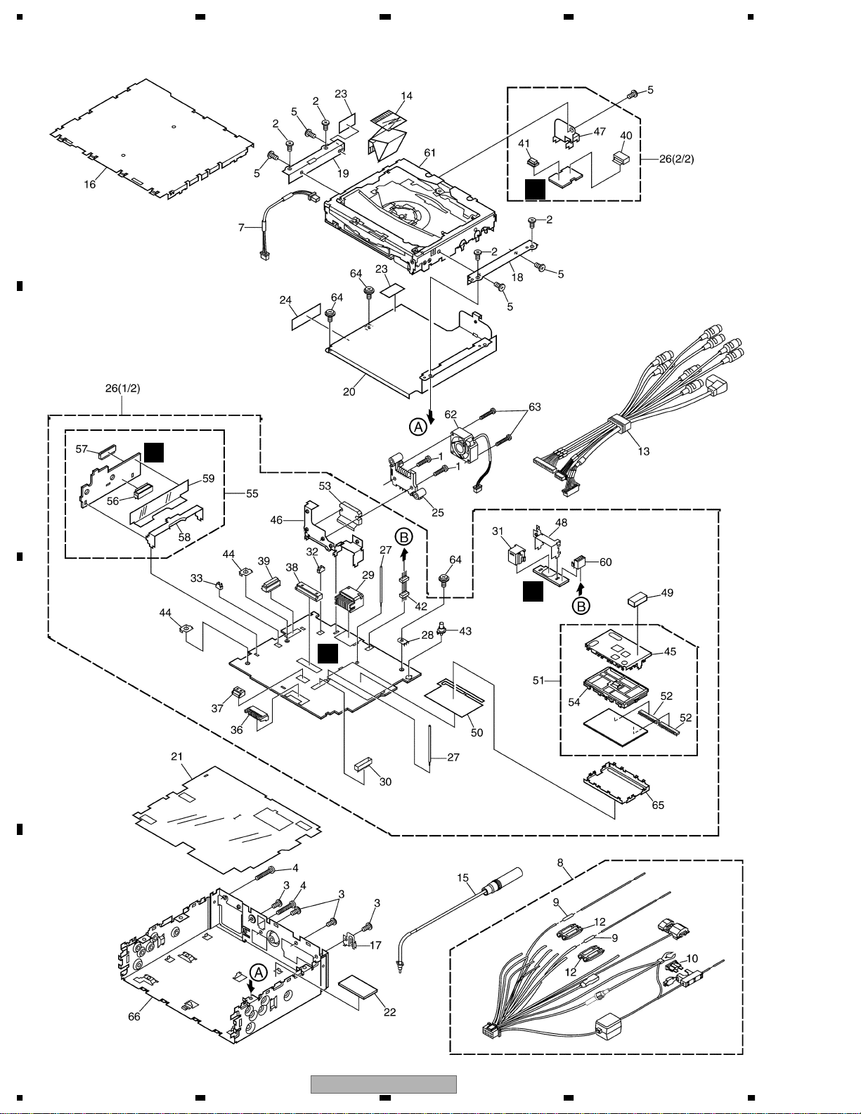
2.7 EXTERIOR(2)(DVH-P7000/UC,DVH-P7050/ES/RC,DVH-P7050/ES/RD)
A
D
B
F
E
A
C
D
22
1234
DVH-P7000R

A
B
5678
(1)EXTERIOR(2)(DVH-P7000/UC,DVH-P7050/ES/RC,DVH-P7050/ES/RD) SECTION PARTS LIST
No. Description Part No.
Mark
No. Description Part No.
1 Screw BMZ26P120FMC
2 Screw BSZ26P060FMC
3 Screw BSZ30P060FMC
4 Screw BSZ30P200FMC
5 Screw(M2x2.2) CBA1419
6 •••••
7 Cord CDE6574
8 Cord Assy CDE6761
9 Resistor RS1/2PMF102J
10 Fuse(10A) CEK1136
11 •••••
12 Cap CNS1472
13 Cord Assy CDE6762
14 Cable CDE6766
15 Cord CDH1208
16 Case CNB2732
17 Holder CNC4963
18 Holder CNC9793
19 Holder CNC9794
20 Holder CND1196
21 Insulator CNM7632
22 Spacer CNM7634
23 Sheet CNM7834
24 Sheet CNM7835
25 Heat Sink CNR1617
26 Tuner Amp Unit See Contrast table(2)
27 Clamper CEF1009
28 Terminal(CN401) CKF1059
29 Plug(CN802) CKM1370
30 Plug(CN171) CKS1043
31 Connector(CN1602) CKS2104
32 Connector(CN801) CKS3124
33 Connector(CN971) CKS3124
34 •••••
35 •••••
Mark
36 Plug(CN101) CKS3537
37 Connector(CN202) CKS3598
38 Connector(CN301) CKS3606
39 Connector(CN201) CKS3661
40 Connector(CN1702) CKS3902
41 Connector(CN1701) CKS4496
42 Connector(CN972) CKS4581
43 Mini Pin Jack(CN402) CKX1046
44 Holder CNC5399
45 Case CNC8709
46 Holder CNC9788
47 Holder CNC9791
48 Holder CNC9792
49 Cushion CNM6870
50 Insulator CNM7640
51 FM/AM Tuner Unit CWE1608
52 Connector(CN1,2) CKS4244
53 IC(IC302) PAL007A
54 Holder CNC8708
55 Power Supply Unit CWM8156
56 Connector(CN1002) CKS3660
57 Connector(CN1001) CKS4052
58 Holder CNC9790
59 Insulator CNM7633
60 Connector(CN1601) HKS-193
61 DVD Mechanism Module(MS2) CXK6151
62 Fan Motor(M801) CXM1193
63 Screw PMZ20P160FMC
64 Screw ISS26P055FUC
65 Case CNC8710
66 Chassis CNA2486
C
(2) CONTRAST TABLE
DVH-P7000/UC, DVH-P7050/ES/RC and DVH-P7050/ES/RD are constructed the same except for the following:
Mark NO Symbol and Description DVH-P7000/UC DVH-P7050/ES/RC DVH-P7050/ES/RD
26 Tuner Amp Unit CWM8153 CWM8154 CWM8155
DVH-P7000R
56
7
23
8
D
1234
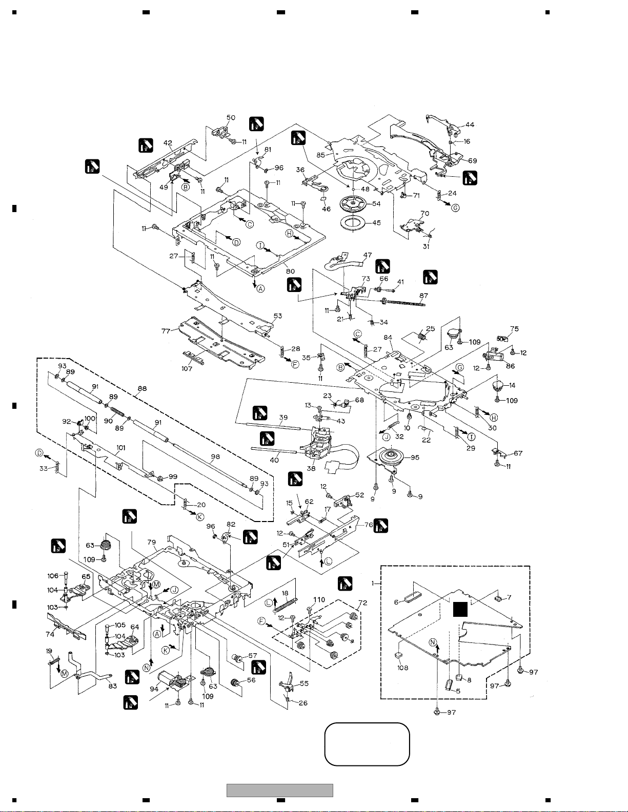
2.8 DVD Mechanism Module
A
(A)
(Recess)
(B)
(All over)
(Recess)
(A)
(A)
(B)
(Claw only)
(B)
(B)
(Excluding the gear)
(B)
B
(B)
(B)
(B)
(All over)
C
(Hole)
(A)
(A)
(The fluing under)
(A)
(Recess)
(B)
(All over)
(B)
(All geras)
(A)
(Recess)
G
(A)
(Shaft)
D
(B)
(Two gears)
24
1234
(B)
(A) : GEM1024
(B) : GEM1040
DVH-P7000R

A
B
5678
DVD Mechanism Module SECTION PARTS LIST
Mark
No. Description Part No.
1 DVD core unit V CWX2706
2-4 •••••
5 Connector(CN1100) CKS3749
6 Connector(CN1701) CKS4052
7 Connector(CN1700) CKS4374
8 Connector(CN1300) CKS4507
9 Screw(M2x3) CBA1486
10 Screw CBA1535
11 •••••
12 Screw(M2x2.2) CBA1548
13 Screw(M1.4x2) CBA1549
14 Damper CNV6927
15 Washer CBF1038
16 Spring CBH2394
17 Spring CBH2395
18 Spring CBH2396
19 Spring CBH2397
20 Spring CBH2398
21 Spring CBH2399
22 Spring CBH2400
23 Spring CBH2401
24 Spring CBH2402
25 Spring CBH2403
26 Spring CBH2404
27 Spring CBH2405
28 Spring CBH2406
29 Spring CBH2407
30 Spring CBH2408
31 Spring CBH2410
32 Spring CBH2411
33 Spring CBH2413
34 Spring CBH2414
35 Spring CBL1499
36 Spring CBL1500
37 •••••
38 Pickup Unit(Service)(DP4) CXX1530
39 Shaft CLA3878
40 Shaft CLA3879
41 Shaft CLA3881
42 Lever CNC8988
43 Bracket CNC8992
44 Arm CNC8994
45 Sheet CNM6883
46 Sheet CNM6884
47 PCB CNP5971
48 Ball CNR1189
49 Guide CNV6352
50 Guide CNV6353
51 Guide CNV6354
52 Guide CNV6355
53 Guide CNV6356
54 Clamper CNV6357
55 Arm CNV6358
56 Gear CNV6361
No. Description Part No.
Mark
57 Gear CNV6362
58-61 •••••
62 Rack CNV6367
63 Damper CNV6368
64 Arm CNV6369
65 Arm CNV6370
66 Gear CNV6372
67 Holder CNV6374
68 Rack CNV6376
69 Arm CNV6377
70 Arm CNV6378
71 Arm CNV6379
72 Gear Unit CXB5959
73 Holder CNV6383
74 Guide CNV6384
75 Holder CNV6385
76 Lever Unit CXB5943
77 Holder Unit CXB5944
78 •••••
79 Frame Unit CXB5948
80 Frame Unit CXB5949
81 Arm Unit CXB5950
82 Arm Unit CXB5951
83 Arm Unit CXB5952
84 Chassis Unit CXB5953
85 Arm Unit CXB5954
86 Motor Unit(CRG) CXB5955
87 Screw Unit CXB5957
88 Roller Unit CXB5958
89 Washer CBF1060
90 Spring CBH2170
91 Roller CNV6068
92 Holder CNV6210
93 Washer YE20FUC
94 Motor Unit(LOAD) CXB5960
95 Motor Unit(SPDL) CXB6218
96 Washer YE15FUC
97 Screw IMS20P030FMC
* 98 Shaft CLA3877
* 99 Gear CNV6359
* 100 Caller CNV6382
* 101 Arm Unit CXB5945
102 •••••
103 Washer CBF1087
104 Roller CNV6928
105 Shaft CLA4180
106 Shaft CLA4181
107 Guide CNV6805
108 Connector(CN1702) CKS4282
109 Screw (M2x3.5) CBA1560
110 Screw (M2x2.2) CBA1419
C
D
DVH-P7000R
56
7
8
25
1234
1
1
4
8
3
8
C
8
C
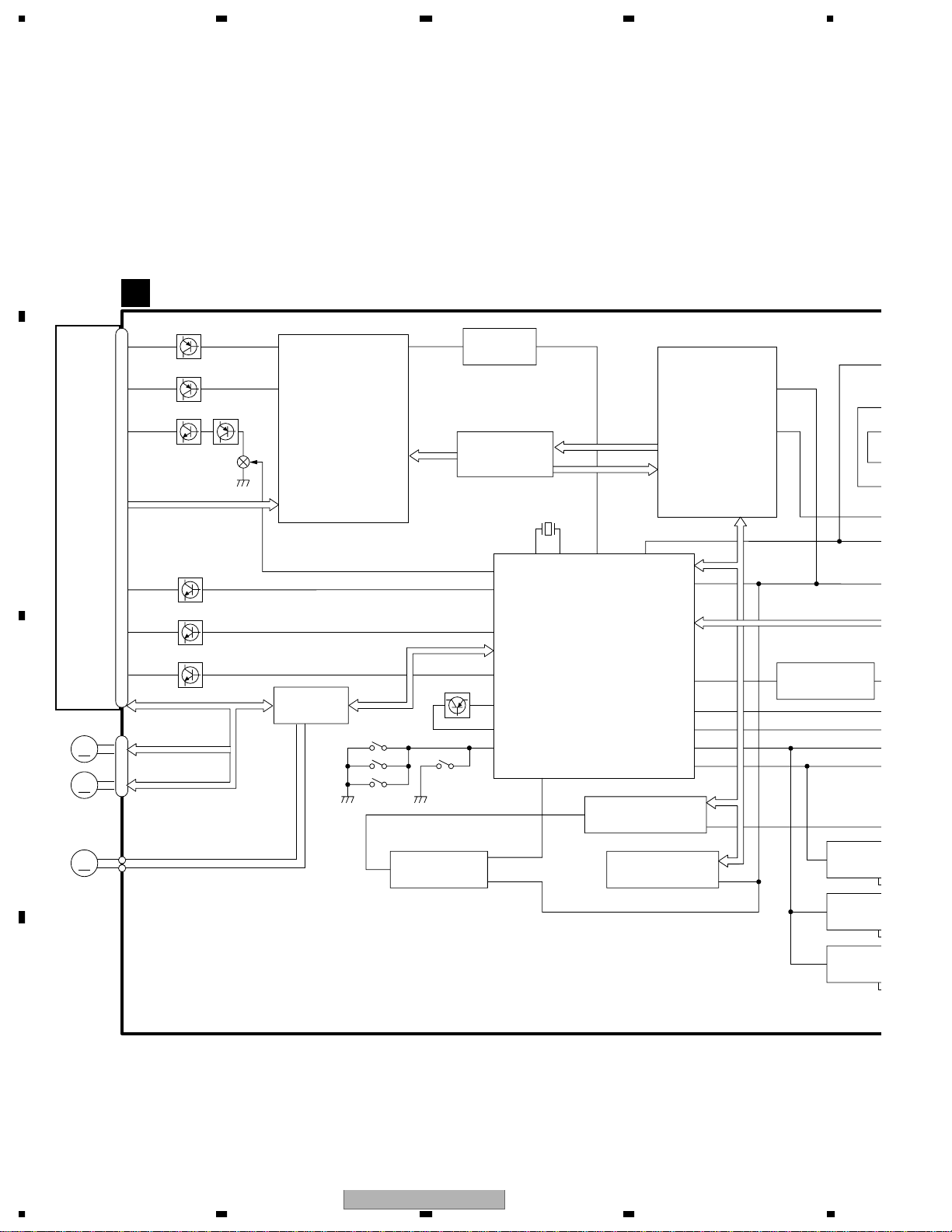
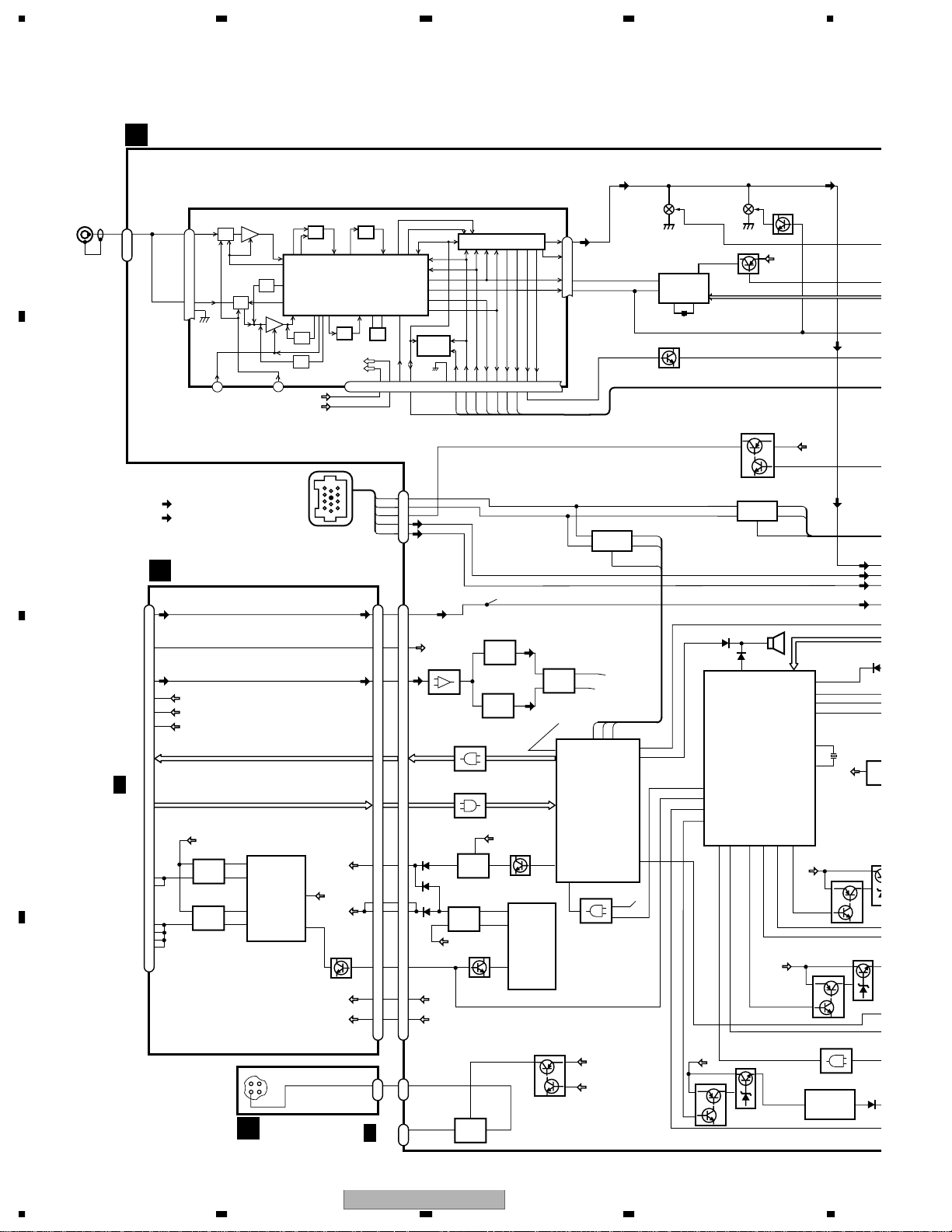
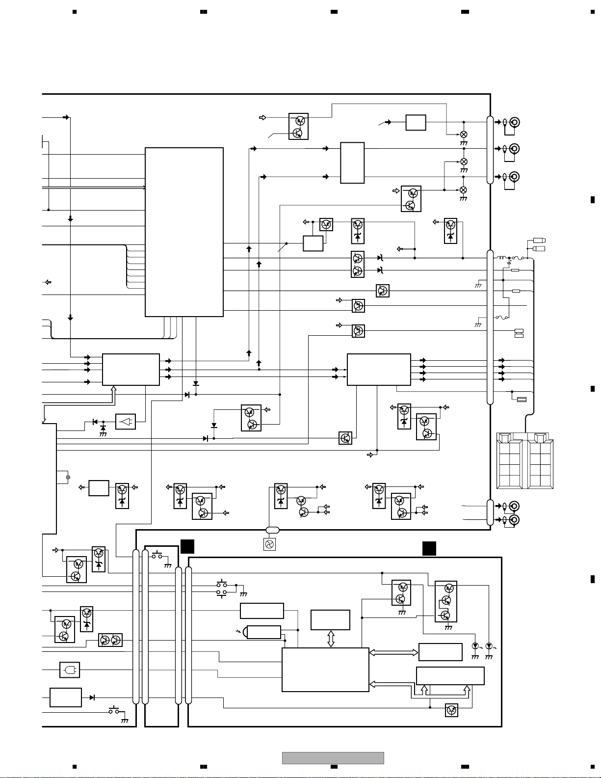
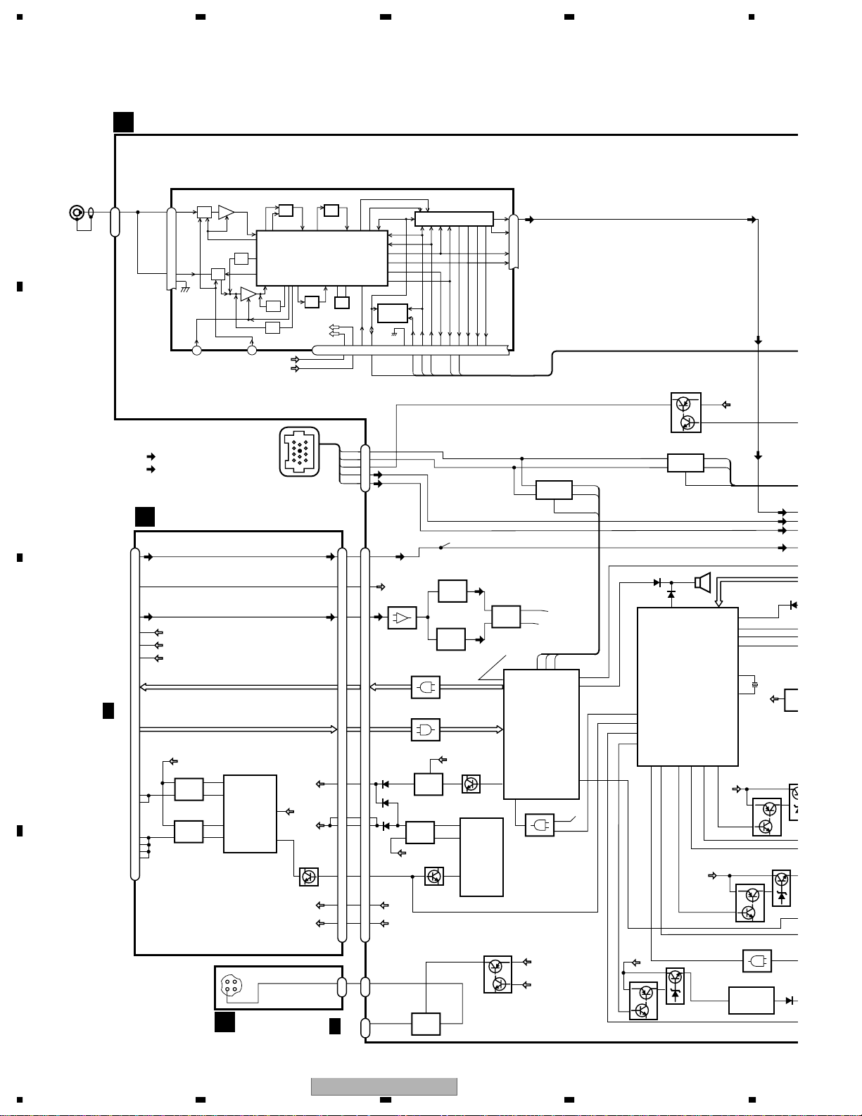
3. BLOCK DIAGRAM AND SCHEMATIC DIAGRAM
3.1 BLOCK DIAGRAM(1)
A
DVD CORE UNIT V
G
B
C
PICKUP UNIT(SERVICE)(DP4)
SPINDLE
MOTOR
M
M
CARRIAGE
MOTOR
M
LOADING
MOTOR
CN1100
30
28
27
6
7
8
CN1300
Q1104
65LD
Q1108
78LD
Q1102
VSHF
A,B1-4,C,RF+,RF-
LCDSG1
LCDSG2
LCDSG3
Q1109
Q1110
Q1111
FOP,FOM,TOP,TOM
EC,CONT
COP,COM
Q1105
241
LPC01 RFENV
4
LPC02
FEP
IC 1100
Q1107
AN8702FH
DRIVER BLOCK
IC 1300
BA5985FM
9
10
LOM
LOP
8cm
detect
SW
12cm detect SW
S1304
S1303
S1302
57
IC 1101
NJM2904M
ADSC
IC 1200
MN677061ZYUB
GBAL,
TBAL,
FBAL
94
CD/DVD
23
TILT1
36
TILT2
33
71
83
79
TILT3
AVREF
ADENA
DSCSNS
Q1700
S1301
CLAMP SW
L/E ON/OFF SW
3
IC 1704
TC74VCX08FT
2
1
PCADATA,
PACLRCK
DAT,
X1700
5MHz
62 63 78 90
X2 X1
XUWR
96
CHECK40
X2ENV
CPU
IC 1700
PE5321A
SRAM
17
IC 1701
M5M5V216ATP-70HI
FLASH MEMORY
IC1702
PD6384A
ODC
IC 1400
MNZS25BDAUB
97
XWR
CLKOUT
59 2
XRES
FSSW
VCONTA
VCONTB
107
86
116
117
XCSSRAM
6
11
59
XWR
100
MCK33
A0-17,D0-15
IC 1705
TC7SH04FU
1
BA03
1
BA18B
1
BA00B
IC 1
4
IC 1
4
IC 1
4
D
26
DVH-P7000R
1234

A
B
5678
IC 1705
C7SH04FU
3
IC 1509
TC74VCX74FT
3
IC 1503
2
TC74VCX74FT
12
IC 1504
10
TC74VCX04FT
42
IC 1706
TC7SH32FU
5
11
8
13
11
4
1
33
30
AV CHIP
IC 1502
MN677532JAUB
HCLK
XBWR
VGOUT
CLK27
124 99 110
85
IEC958
EXTCK
CTS,DTR,RXPC,TXPC,VPP,SICOMN,
SOCOMN,SCKCOMN
SDRAM
IC 1500
M2V64S40DTP-6L
CLOCK GEN
22
24
IC 1506
SM8703AV
23
1
7
12
CN1702
VCC33
CN1700
VCONTA
VCONTB
1
CN971
A
D
CN1701
11
12
TXD,RXD,DTR,CTS
EXTENSION PCB
CN1702
C
1
IC 1802
BA033SFP
1
IC 1803
BA18BC0WFP
1
IC 1804
BA00BC0WFP
Q1601
2
4
2
4
2
4
VD63
VCC33
VCC18
VCC27
EXTCK,SRCKAV,AOUT0,LRCKAV
1
IC 1601
AK4380VT
31
F1600
Q1602,Q1604
11
10
Q1600
Q1603
CN1701
VIDEO OUT
VCONTB
SRAM+3.3V
CPU+3.3V
VCC
AMUTE
Lch OUT
Rch OUT
28
23
22
15
12
6
5
CN1001
F
D
DVH-P7000R
56
7
27
8
1234
4
4
4
4
1
K
C
0
8
3.2 BLOCK DIAGRAM(2)(DVH-P7000R/EW)
MOTHER PCB
A
A
ANT
1
CN402
FM/AM TUNER UNIT
AMRF
AMANT
28
ATT
ANT1 ADJ
FMANT
27
26
RFGND
ATT
FMRF
LOCH
23
FM/AM 1ST IF 10.7MHz
T51 Q51 CF51
MIXER, IF AMP, DET.
CF202
AM 2ND IF
RF ADJ
450kHz
ANT2 ADJ
LOCL
VCC
VDD
CF52 CF53
MPXREF 41kHz
AMDET
IC1
19
CREQ
DI/DO
IC 3
EEPROM
NC
FMLOCL
924
DGND
11
CE2CKCE1
X901
10.25MHz
VDD
VCC
NCNCWC
20177
222510 14 12 15 16 8 13 2 3 4
IC 2 FM MPX
SDBWSLFMSD
A
Q506 Q504
L ch
A
6
R ch
5
COMP
21
LDET
18
STIND
NL1
NL2
1
RDS
DECODER
20
8
Q502
IC 501
PM4009A
X501
SWDACC
24
1211
Q501
Q505
VDD
Q172
A
A
BU14
B
CN171
A
51 51
V
65
36
35
34
30
70 70
1
I
10
4
2/2
G
CN1702
4
1
7
A
5
A
10
CN201
A
14
CONTB
5959
ISOLATOR
IC 206
V
2
65
NJM2367V
DVD CONTROLLER MS2
TC74VHCT08FT
IC 204
←
MS2 DVD CONTROLLER
TC74VHCT08FT
IC 202
SRAM3V
36
S-814A33AMC-BCX
CPU3V
35
34
30
1
I
10
1
1
DDCONT
CN972
CN971
DAC5
DDBU
Q 201
8,7
DDBU
C
NJM2246M
3
IC 205
1
NJM2246M
1
7
IC 208
←
VDD
1
Q206
35
IC 201
17
45
OUT_D
19
2
OUT_U
TPS5103IDB
Q201
5
RT
3.3V DC-DC CONVERTER
8
32
IC 971
TC7WT125FU
7
V
V
IC 203
75Ω DRIVER
BA7623F
3
IC 207
4
D
27
RMUTE
DVD CONTROLLER
34
MSMCVD
RESET
11
Q971
Q972
IP-BUS DRIVER
5
IC 701
6
HA12187FP
7
FRONT
A
REAR
6
B
86 85 25
TX
RX
IC 702
PE5303A
IC 601
4
TC7SH08FU
RESET
VDD
CONTB
8
MUTE
IPPW
REM
2
RSTCNT
1
IPPW
PEE
BUSBUS+
TX
1
RX
2
BUS+L
BUS-L
MS2 L
28
100
65
24
92
12
91
E
A
: AUDIO SIGNAL
V
: VIDEO SIGNAL
IP BUS
POWER SUPPLY UNIT
F
26
26
8
13
13
35
36
7
CN1001
A
V
LCH
CONTB
VIDEO
SRAM3.3V
CPU3.3V
DAC+5V
MSAMUTE,TMODE,DSKST,RXH
CN1002
C
2/2
G
CN1701
8
Q 1081
VD
9
10
6
Q 1051
+5V
37
38
39
40
D
XRST,TXH,IRQPW
B.U.
+5V, VD DC-DC CONVERTER
29
2
OUT1_U
45,6
27
OUT1_D
IC 1001
TPS5103IDBT
17
4
OUT2_U
27,8
19
OUT2_D
CN1602
123
1
4
OPTICAL PCB
E
SRAM3.3V
11
B.U.
VCC
CPU3.3V
6
RT
Q1001
DAC+5V
B.U.
CN1601
Q171
IP-BUS DRIVER
5
IC 171
6
HA12187FP
8
BUZZER
SP601
18
PEE
IC 603(2/2)
PE5282A
SYSTEM CONTROLLER
MS2RST
DDCONT
dsens
OELPW
SWVDD
DPDT
KYDT
100
BU
Q109
RDT083RDT1
82
3
1
Q108
IPPW
BU
1
2
AMPMUTE
PBSENS
33
TX
RX
BUS+L
BUS-L
MS2 L
79
LVLINL
25
30
31
SYSPW
38
X2
39
X1
ILMPW
BU
Q107
IC 101
TC7SET08FU
6 1
IC 102
NJM2360M
A
A
TUN L
A
A
A
VST,VC
LEVEL INDI
X601
TUNE
3
TUN5
S-8125
Q105
Q106
24
IC
Q
28
DVH-P7000R
1234
A
B
ILMPW
L
A
BU14
TX
RX
BUS+L
BUS-L
MS2 L
79
VLINL
25
MUTE
30
BSENS
31
YSPW
38
X2
39
X1
LER
BU
Q107
IC 101
TC7SET08FU
6 1
IC 102
NJM2360M
A
A
ELECTRONIC VOLUME/
A
TUN L
41
A
43
A
44
A
42
VST,VCK,VDT
LEVEL INDICATOR
X601
TUNER 5V REGULATOR
TUN5
IC 801
S-81250SGUP
Q104
Q105
Q106
Q102
24
5678
60
47
94
61
78
49
77
62
68
8
67
7
29
SOURCE SELECTOR
IN2-L
IN4+L
IC 361
IN4-L
PML009A
IN3-L
IC 681
NJM4558MD
Q816
23
CN101
SWDVDD
Q101
DPDT
S101
DSENS
KYDT
OELB
REM
ILB
SEL_OUT_L
1
57
BU
8
7
12
13
2
11
11
14
14
10
10
BU14
D
TMUTE
FM/AM
SYSTEM CONTROLLER
IC 603(1/2)
PE5282A
LDET
NL2DT
NL1
SD
SL
SDBW
TUNPCE
TUNPCK
TUNPCE2
TUNPDO
ASENBO
TXRXIPPW
27 26 28
75
A
12
PL
A
10
FL
A A
11
RL
DAC 5V REGULATOR
Q804
DAC5
S1850
8
EJECT
7
2
1
CN1850
CN1851
4
7
9
2
1
10
8
5
reset
BSENS
ASENS
ISENS
TELIN
EJTIN
MUTE
30
Q806
PANEL UNIT
B
CN1901
ILB
9
RDT1
612
RDT0
413
SWVDD
11
REM
121
DPDT
3
KYDT
5
OELB
8
VOLUME
A
34
A
90
91
85
71
SYS+B
A
A
A
Q306
Q307
CONTB
CN801
FAN MOTOR
S1930
DSENS
3.3V REGULATOR
IC 1904
S-818A33AUC-BGN
REMOTE CONTROL SENSOR
OPT IN
IC 1903
TSOP1840SB3V
A
E
BU
FAN 9V REGULATOR
Q801
2
M801
3
1
5
27
28
MUTE
Q305
VDD
RSTCNT
4
S-87503BUP-ABF
Q802
15
14
VDD
REM
DPDT
OEL CONTROLLER/
KTDT
HIGH OUTPUT
PL
A
FL
A
VDD REGULATOR
Q814
1
IC 803
5
BACKUP SENSE
VDD
TELEPHONE MUTE
VDD
PARKING BRAKE SENSE
A
12
14
MUTE
BU
Q803
SYSPW
CONTB
FONT ROM
IC 1902
PD8094A
KEY CONTROLLER
IC 1901
PD5766A
IC 303
PA2028A
Q815
Q813
ACC SENSE
Q810
Q810
FLIN
RLIN
22 4
Q302
SYSPW
CONTB
VIDEO5
32
KEY DATA
OEL DATA
A
MS2L
C
NJM4558MD
187
159
MUTE
Q312
RBU14
BU14
ACC
Q808
ILL SENSE
POWER AMP
FL-
B.REMOTE
25
AUDIO 8V REGULATOR
Q809
SYS+8
Q805
Q807
Q1961
Q1962
FL+
RL-
RL+
IC 302
PAL007A
STBYMUTE
VIDEO 5V REGULATOR
ILMD
13
IC 301
DDBU REGULATOR
DDBU
BU
A
3
A
5
23
A
A
21
Q807
BU
C
KEY MATRIX
CN301
Q310
Q311
Q314
Q207
CN802
BU
CN202
CONTB
REAR
B
FRONT
A
SYSPW
KEYBOARD UNIT
Q1963
GREEN
Q1964
Q1965
AMBER
OEL UNIT
4,16
2,8
Q1941
A
A
REAR
MONITOR L
NON FADER OR
11
PL
7
SUB WOOFER L
A
FL
3
1
5
2
3
8
6
7
10
12
9
11
4
1
3
FUSE
0.5A
V
V
A
A
A
A
BACK
UP
ILL
GND
FRONT L
FUSE
BACK UP
10A
1K(1/2w)
ACC
GND
1K(1/2w)
ILL
TELMUTE
PBSEN
FL-
FL+
RLRL+
B.REM
B.
REM
ACC
FRONT VIDEO
OUTPUT
REAR VIDEO
OUTPUT
RR
RR
+
FR
FR
+
FL
FL
+
RL
RL
+
-
C
D
DVH-P7000R
56
7
8
29
A
4
4
4
4
1
K
C
0
8
1234
3.3
BLOCK DIAGRAM(2)(DVH-P7000/UC,DVH-P7050/ES/RC,DVH-P7050/ES,RD)
MOTHER PCB
A
FM/AM TUNER UNIT
ANT
1
CN402
FM/AM 1ST IF 10.7MHz
AMRF
AMANT
28
ATT
T51 Q51 CF51
ANT1 ADJ
FMANT
27
26
RFGND
ATT
FMRF
RF ADJ
ANT2 ADJ
LOCH
23
LOCL
MIXER, IF AMP, DET.
CF202
AM 2ND IF
450kHz
VCC
VDD
CF52 CF53
IC1
VDD
VCC
MPXREF 41kHz
AMDET
IC 2 FM MPX
19
CREQ
DI/DO
IC 3
EEPROM
NC
FMLOCL
924
DGND
11
CE2CKCE1
X901
10.25MHz
NCNCWC
20177
222510 14 12 15 16 8 13 2 3 4
SDBWSLFMSD
L ch
A
6
R ch
5
COMP
21
LDET
18
STIND
NL1
NL2
1
SWDACC
Q172
A
A
BU14
B
CN171
A
51 51
V
65
36
35
34
30
70 70
1
I
10
4
2/2
G
CN1702
4
1
7
A
5
A
10
CN201
A
14
CONTB
5959
ISOLATOR
IC 206
V
2
65
NJM2367V
DVD CONTROLLER MS2
TC74VHCT08FT
IC 204
←
MS2 DVD CONTROLLER
TC74VHCT08FT
IC 202
SRAM3V
36
S-814A33AMC-BCX
CPU3V
35
34
30
1
I
10
1
1
DDCONT
CN972
CN971
DAC5
DDBU
Q 201
8,7
DDBU
C
NJM2246M
3
IC 205
1
NJM2246M
1
7
IC 208
←
VDD
1
Q206
35
IC 201
17
45
OUT_D
19
2
OUT_U
TPS5103IDB
Q201
5
RT
3.3V DC-DC CONVERTER
8
32
IC 971
TC7WT125FU
7
V
V
IC 203
75Ω DRIVER
BA7623F
3
IC 207
4
D
27
RMUTE
DVD CONTROLLER
34
MSMCVD
RESET
11
Q971
Q972
IP-BUS DRIVER
5
IC 701
6
HA12187FP
7
FRONT
A
REAR
6
B
86 85 25
TX
RX
IC 702
PE5303A
IC 601
4
TC7SH08FU
RESET
VDD
CONTB
8
MUTE
IPPW
REM
2
RSTCNT
1
IPPW
PEE
BUSBUS+
TX
1
RX
2
BUS+L
BUS-L
MS2 L
28
100
65
24
92
12
91
E
A
: AUDIO SIGNAL
V
: VIDEO SIGNAL
IP BUS
POWER SUPPLY UNIT
F
26
26
8
13
13
35
36
7
CN1001
A
V
LCH
CONTB
VIDEO
SRAM3.3V
CPU3.3V
DAC+5V
MSAMUTE,TMODE,DSKST,RXH
CN1002
C
2/2
G
CN1701
8
VD
9
10
6
+5V
37
38
39
40
D
XRST,TXH,IRQPW
B.U.
+5V, VD DC-DC CONVERTER
29
2
45,6
4
27,8
OUT1_U
27
OUT1_D
TPS5103IDBT
17
OUT2_U
19
OUT2_D
1
4
E
IC 1001
CN1602
123
OPTICAL PCB
Q 1081
Q 1051
SRAM3.3V
11
B.U.
VCC
CPU3.3V
6
RT
Q1001
DAC+5V
B.U.
CN1601
Q171
IP-BUS DRIVER
5
IC 171
6
HA12187FP
8
BUZZER
SP601
18
PEE
IC 603(2/2)
PE5283A
SYSTEM CONTROLLER
MS2RST
DDCONT
dsens
OELPW
SWVDD
DPDT
KYDT
100
BU
Q109
RDT083RDT1
82
3
1
Q108
IPPW
BU
1
2
AMPMUTE
PBSENS
33
TX
RX
BUS+L
BUS-L
MS2 L
79
LVLINL
25
30
31
SYSPW
38
X2
39
X1
ILMPW
BU
Q107
IC 101
TC7SET08FU
6 1
IC 102
NJM2360M
A
A
TUN L
A
A
A
VST,VC
LEVEL INDI
X601
TUNE
3
TUN5
S-8125
Q105
Q106
24
IC
Q
30
DVH-P7000R
1234
 Loading...