

Page 1
INSTALLATION MANUAL
DVH-P6050UB
INSTALLATION MANUAL
English Français
Italiano
Nederlands
Page 2

1
Connecting the Units ................................ 1
Power cable connection .................................... 3
Connecting to separately sold power amp ........ 5
When connecting with a multi-channel
processor .................................................... 7
Connecting and installing the optical cable
connection box .......................................... 8
When using a display connected video
outputs ........................................................ 9
When connecting with a rear view camera .... 10
Installation ................................................ 11
DIN Front/Rear-mount .................................... 12
DIN Front-mount ............................................ 12
DIN Rear-mount .............................................. 13
Connecting the Units
Contents
Note:
•When this unit is installed in a vehicle without
ACC (accessory) position on the ignition switch,
red cable must be wired to the terminal that can
detect the operation of the ignition key.
Otherwise, battery drain may result.
•Use this unit in other than the following conditions could result in fire or malfunction.
—Vehicles with a 12-volt battery and negative
grounding.
— Speakers with 50 W (output value) and 4 ohm
to 8 ohm (impedance value).
• To prevent short-circuit, overheating or malfunction, be sure to follow the directions below.
—Disconnect the negative terminal of the bat-
tery before installation.
— Secure the wiring with cable clamps or adhe-
sive tape. To protect the wiring, wrap adhesive tape around them where they lie against
metal parts.
— Place all cables away from moving parts,
such as gear shift and seat rails.
— Place all cables away from hot places, such as
near the heater outlet.
—Do not pass the yellow cable through a hole
into the engine compartment to connect to a
battery.
—Cover any disconnected cable connectors
with insulating tape.
—Do not remove RCA caps if RCA cables are
not used.
—Do not shorten any cables.
—Never cut the insulation of the power cable of
this unit in order to share the power to other
equipment. Current capacity of the cable is
limited.
—Use a fuse of the rating prescribed.
—Never wire the speaker negative cable direct-
ly to ground.
—Never band together multiple speaker’s nega-
tive cables.
No ACC positionACC position
C
C
A
O
F
N
F
O
S
T
A
R
T
O
F
N
F
O
S
T
A
R
T
Page 3

English
Español
Deutsch
Français
Italiano
Nederlands
•Control signal is output through blue/white cable
when this unit is powered on. Connect it to an
external power amp’s system remote control or
the vehicle’s auto-antenna relay control terminal
(max. 300 mA, 12 V DC). If the vehicle is
equipped with a glass antenna, connect it to the
antenna booster power supply terminal.
•Never connect blue/white cable to external power
amp’s power terminal. Also, never connect it to
the power terminal of the auto antenna.
Otherwise, battery drain or malfunction may
result.
• IP-BUS connectors are color-coded. Be sure to
connect connectors of the same color.
•Black cable is ground. This cable and other product’s ground cable (especially, high-current products such as power amp) must be wired separately. Otherwise, fire or malfunction may result if
they are accidentally detached.
2
Page 4
3
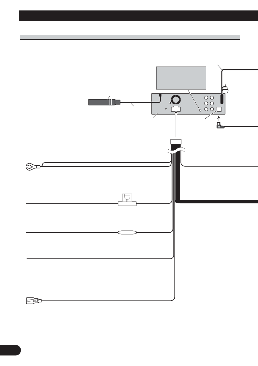
Connecting the Units
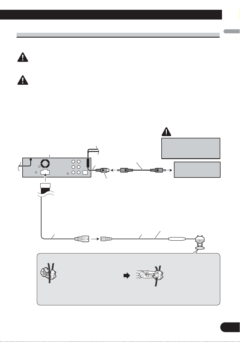
Power cable connection
Violet/white
Of the two lead wires connected to the back lamp,
connect the one in which the voltage changes when
the gear shift is in the REVERSE (R) position.
For details, refer to page 10.
Yellow/black
If you use an equipment with Mute function, wire
this lead to the Audio Mute lead on that equipment.
If not, keep the Audio Mute lead free of any
connections.
Black (chassis ground)
Connect to a clean, paint-free metal location.
Yellow
Connect to the constant 12 V supply terminal.
Red
Connect to terminal controlled by ignition switch (12 V DC).
Fuse (10 A)
Fuse resistor
15 cm
This product
Antenna jack
IP-BUS input
(Blue)
20 cm
AUX jack (3.5 ø)
Use a mini plug cable
to connect with
auxiliary device.
Page 5
English
Español
Deutsch
Français
Italiano
Nederlands
4
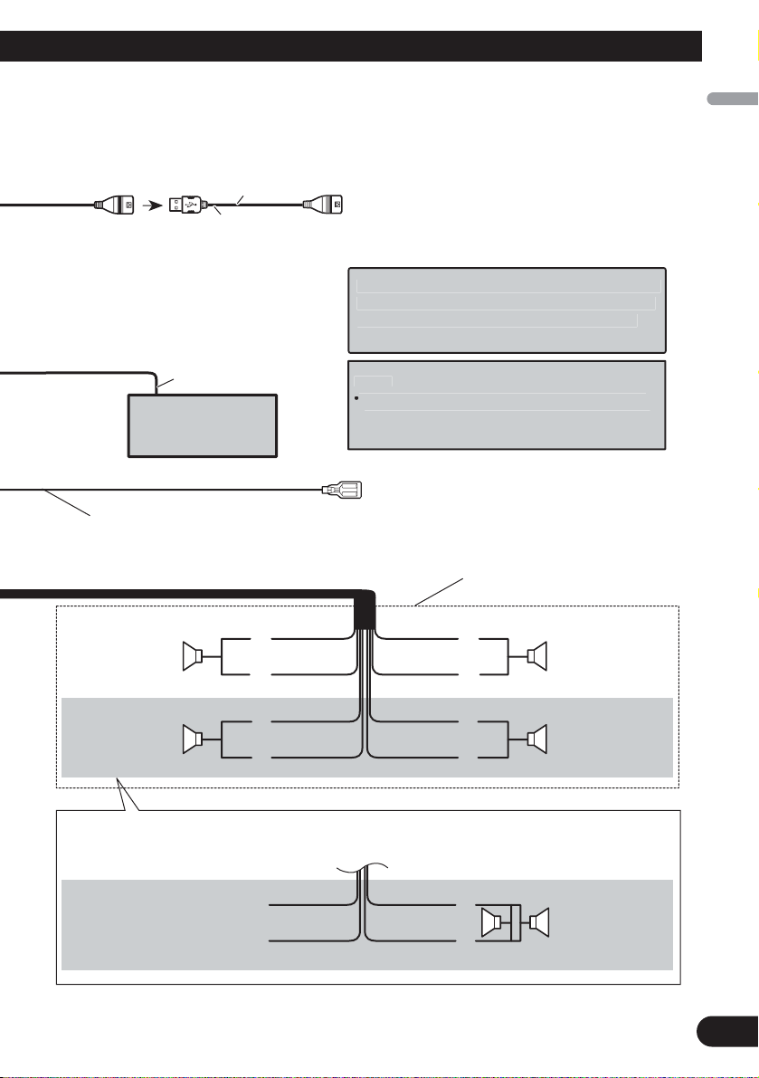
IP-BUS cable
Multi-CD player
(sold separately)
US
ble
C
5 m
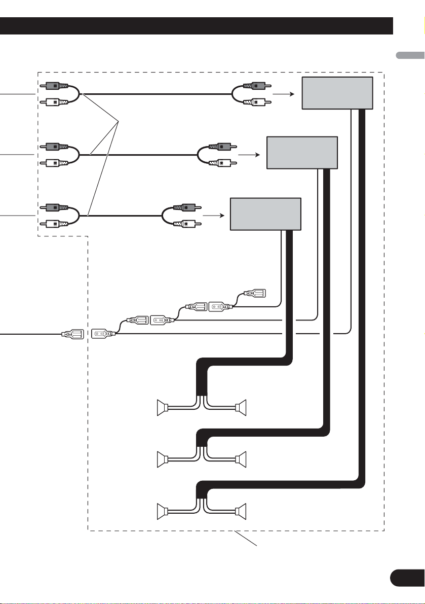
Blue/white
Connect to system control terminal of the power
amp or auto-antenna relay control terminal
(max. 300 mA 12 V DC).
Left Right
Front speaker Front speaker
Rear speaker or
Subwoofer (4 Ω)
White Gray
Gray/blackWhite/black
Green Violet
Green/black Violet/black
Violet
Violet/black
Not used.
Green
Green/black
When using a subwoofer of 70 W (2 Ω), be sure to connect with Violet and Violet/black leads of this unit.
Do not connect anything with Green and Green/black leads.
Subwoofer (4 Ω)
× 2
Rear speaker or
Subwoofer (4 Ω)
With a 2 speaker system, do not connect
anything to the speaker leads that are not
connected to speakers.
N
:
unit is monaural.
Wh
l
p
(bl
+
≠
+
≠
+
≠
+
≠
+
≠
1.
B ca
onnect to separately sold USB device.
en you connect the separately sold multi-channe
rocessor (DEQ-P7650) to this unit, do not connect
anything to the speaker leads and system remote
control
Change the initial setting of this unit (refer to the
ue/white).
otes
Operation Manual). The subwoofer output of this
Page 6
5
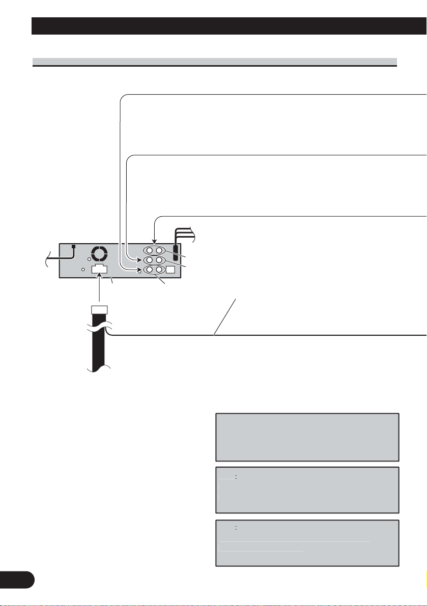
Connecting the Units
Connecting to separately sold power amp
Subwoofer output
Rear output
Front output
When you connect separately sold multi-channel
processor (e.g. DEQ-P7650) to this unit, do not
connect anything to the speaker leads and system
remote control (blue/white).
Note
:
Wh
Note
:
Chang
The subwoofer output of this unit is monaural.
This product
Blue/white
Connect to system control terminal of the power
amp or auto-antenna relay control terminal
(max. 300 mA 12 V DC).
en you connect multi-channel processor to
this unit, separately sold power amp must be
connected to multi-channel processor.
e the initial setting of this product (refer
to the Operation Manual).
Page 7
English
Español
Deutsch
Français
Italiano
Nederlands
6
Connect with RCA cables
(sold separately)
Perform these connections when
using the optional amplifier.
Power amp (sold
separately)
Power amp (sold
separately)
Power amp (sold
separately)
System remote control
Front speaker
Front speaker
+
≠
+
≠
+
≠
+
≠
+
≠
+
≠
Subwoofer Subwoofer
Left Right
Rear speakerRear speaker
Page 8
7
Connecting the Units
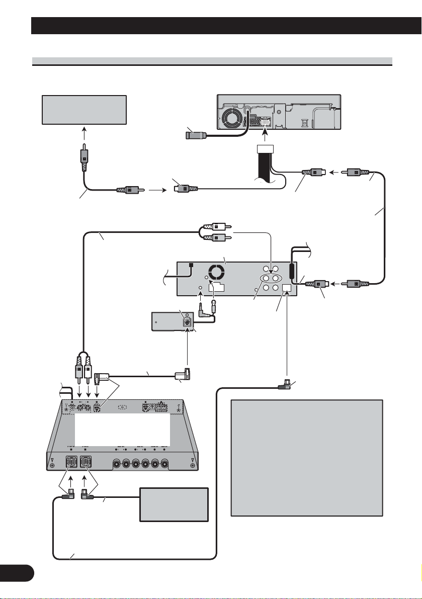
When connecting with a multi-channel processorWhen connecting with a multi-channel processor
Rear view camera
Not used
To video output
Video input 2
(VIDEO 2/BACK
CAMERA INPUT)
RCA cable
(sold separately)
AV system display
(e.g. AVX-7650)
(sold separately)
1.5 m
Video input
(VIDEO INPUT)
RCA cable
(supplied)
RCA cable
(supplied with multichannel processor)
Optical cable
(supplied with multichannel processor)
Multi-channel processor
(DEQ-P7650)
(sold separately)
Black
IP-BUS cable
(supplied with multi-channel
processor)
Blue
IP-BUS cable
Blue
Multi-CD player
(sold separately)
Black
This product
DEQ output
Optical cable connection
box (CD-DD25)
(sold separately)
Black
15 cm
Video output
Blue
If AV system display (e.g. AVX-7650)
is combined with this unit, connect the
rear view camera to the AV system
display. For details concerning
connection methods, refer to AV system
display’s instruction manual.
If AV system display is not combined
with this unit, connect the rear view
camera to this unit’s video input. For
details concerning connection, refer to
page 10.
(VIDEO OUTPUT)
Blue
Page 9
8
English
Español
Deutsch
Français
Italiano
Nederlands
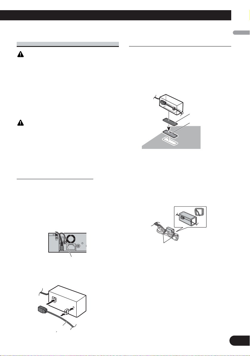
Connecting and installing the
optical cable connection box
WARNING
•Avoid installing this unit in locations where the
operation of safety devices such as airbags is prevented by this unit. Otherwise, there is a danger of
a fatal accident.
•Avoid installing this unit in locations where the
operation of the brake may be prevented.
Otherwise, it may result in a traffic accident.
•Fix this unit securely with the hook and loop fastener or lock tie. If this unit is loose, it disturbs
driving stability, which may result in a traffic accident.
CAUTION
• Install this unit using only the parts supplied with
this unit. If other parts are used, this unit may be
damaged or could dismount itself, which leads to
an accident or other problems.
•Do not install this unit near the doors where rainwater is likely to be spilled on the unit. Incursion
of water into the unit may cause smoke or fire.
Connecting the optical cable
1. Connect the optical cable and
ground lead to the main unit.
Connect the optical cable so that it
does not protrude from the unit, as
shown in the illustration. Fasten the
ground lead to the protrusion on the
back of the unit.
2.
Connect the optical cable to the
optical cable connection box.
Installing the optical cable
connection box
• When
installing the optical cable
connection box with the hook and
loop fastener.
Install the optical cable connection box
using the hook and loop fastener in the
ample space of the console box.
•When installing the optical cable
connection box with the lock tie.
Wrap the optical cable and connection
box with the protection tape and fasten
with the power code using the lock tie.
Screw
Optical cable
Hook fastener
Loop fastener
Wrap with the protection tape
Fasten with the lock tie
Page 10
9
Connecting the Units
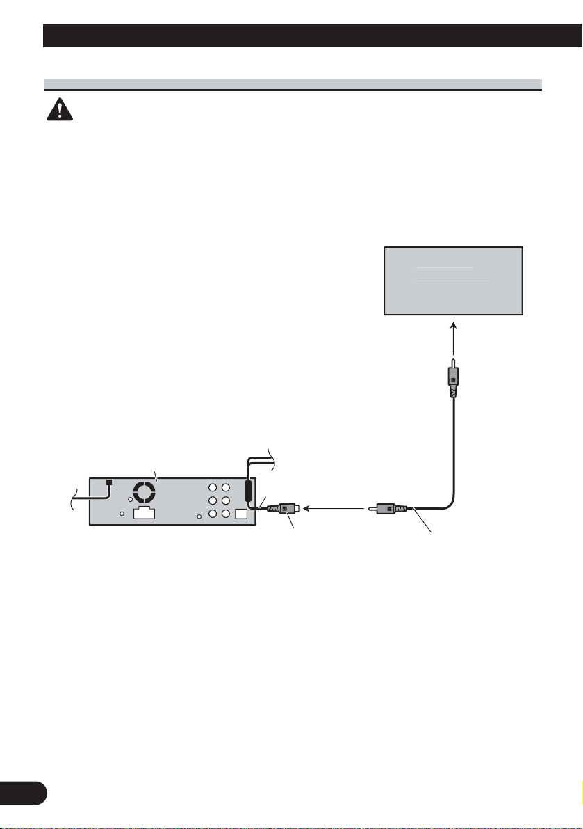
When using a display connected video outputs
WARNING
NEVER install the display in a location that enables the Driver to watch the DVD or Video CD
while Driving.
Display with
ks
t
(supplied
5 m
RCA input jac
To video inpu
This product
15 cm
Video output
(VIDEO OUTPUT)
1.
RCA cable
)
Page 11
10
English
Español
Deutsch
Français
Italiano
Nederlands
When connecting with a rear view camera
When this product is used with a rear view camera, it is possible to automatically switch
from the video to rear view image when the gear shift is moved to REVERSE (R).
WARNING
USE INPUT ONLY FOR REVERSE OR MIRROR IMAGE REAR VIEW CAMERA. OTHER USE MAY
RESULT IN INJURY OR DAMAGE.
CAUTION
• The screen image may appear reversed.
• The rear view camera function is to use this product as an aid to keep an eye on trailers, or backing into a
tight parking spot. Do not use this function for entertainment purposes.
• The object in rear view may appear closer or more distant than in reality.
CAUTION
You must use a camera
This product
15 cm
RCA cable
(sold separately)
which outputs mirror
reversed images.
Rear view camera
Video input
(VIDEO INPUT or REAR
VIEW CAMERA INPUT)
Violet/white
Of the two lead wires connected to the back lamp, connect the one in
which the voltage changes when the gear shift is in the REVERSE (R)
position. This connection enables the unit to sense whether the car is
moving forwards or backwards.
15 cm
Connection method
1. Clamp the lead.
Note:
It is necessary to set VIDEO IN to CAMERA in initial settings when connecting the rear view
camera.
8 m
To video output
Extension lead (supplied)
Fuse resistor
2. Clamp firmly with
needle-nosed
pliers.
Page 12
11
Installation
Note:
•Check all connections and systems before final
installation.
• Do not use unauthorized parts. The use of
unauthorized parts may cause malfunctions.
•Consult with your dealer if installation requires
drilling of holes or other modifications of the
vehicle.
•Do not install this unit where:
— it may interfere with operation of the vehicle.
— it may cause injury to a passenger as a result
of a sudden stop.
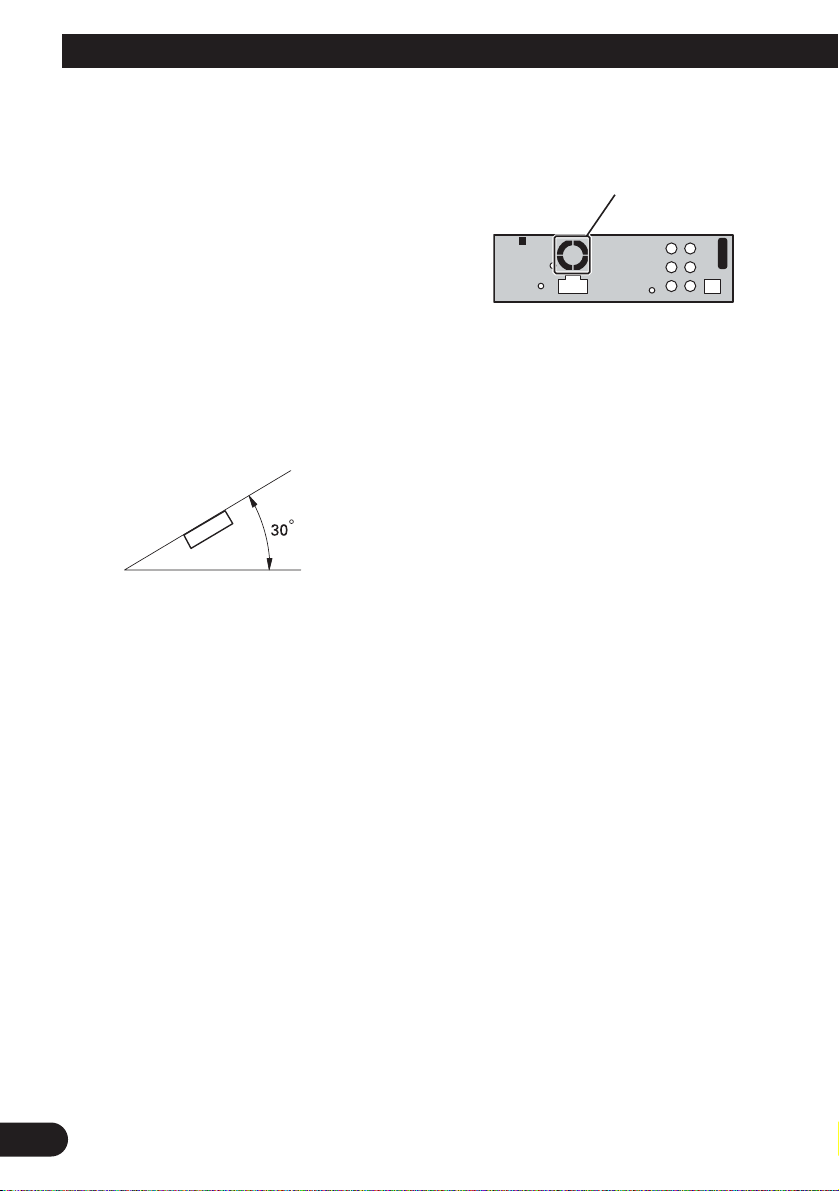
• The semiconductor laser will be damaged if it
overheats. Install this unit away from hot places
such as near the heater outlet.
•Optimum performance is obtained when the unit
is installed at an angle of less than 30°.
•The cords must not cover up the area shown in
the figure below. This is necessary to allow the
amplifires to radiate freely.
•When installing, to ensure proper heat dispersal
when using this unit, make sure you leave ample
space behind the rear panel and wrap any loose
cables so they are not blocking the vents.
Do not close this area.
Page 13
DIN Front/Rear-mount
This unit can be properly installed either from
“Front” (conventional DIN Front-mount) or
“Rear” (DIN Rear-mount installation, utilizing
threaded screw holes at the sides of unit chassis).
For details, refer to the following installation
methods.
DIN Front-mount
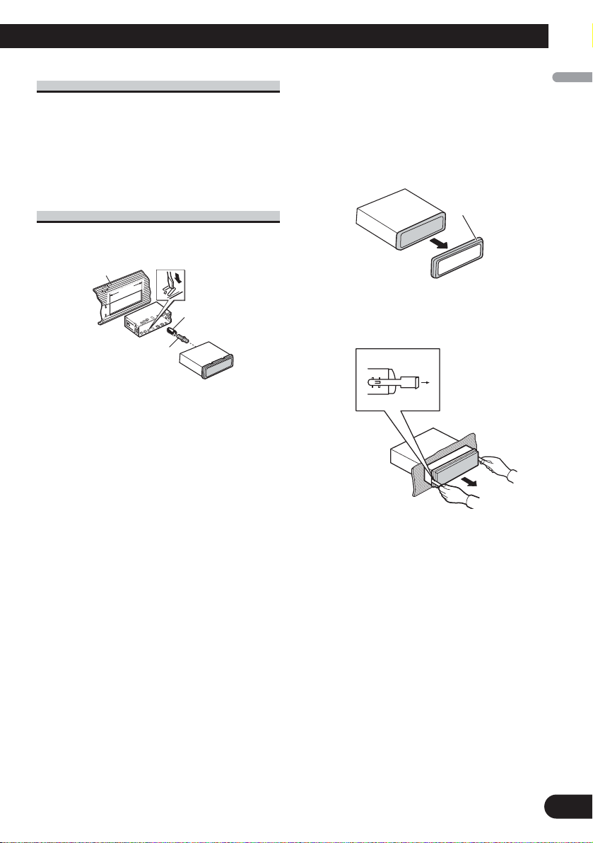
Installation with the rubber bush
1. Insert the mounting sleeve into the dashboard.
•When installing in a shallow space, use a supplied mounting sleeve. If there is enough
space behind the unit, use factory supplied
mounting sleeve.
2. Secure the mounting sleeve by using a screwdriver to bend the metal tabs (90°) into place.
3. Install the unit as illustrated.
Removing the Unit
1. Extend top and bottom of the trim ring outwards
to remove the trim ring. When reattaching the
trim ring, push the trim ring onto the unit until it
clicks. (If the trim ring is attached upside down,
the trim ring will not fit properly.)
• It becomes easy to remove the trim ring if the
front panel is released.
2. Insert the supplied extraction keys into both sides
of the unit until they click into place.
3. Pull the unit out of the dashboard.
53
182182
12
Trim ring
English
Español
Deutsch
Français
Italiano
Nederlands
Rubber bush
Screw
Dashboard
Mounting sleeve
Page 14
13
Installation
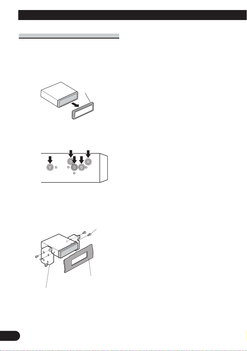
DIN Rear-mount
1. Extend top and bottom of the trim ring outwards
to remove the trim ring. When reattaching the
trim ring, push the trim ring onto the unit until it
clicks. (If the trim ring is attached upside down,
the trim ring will not fit properly.)
• It becomes easy to remove the trim ring if the
front panel is released.
2. Determine the appropriate position where the
holes on the bracket and the side of the unit
match.
3. Tighten two screws on each side.
• Use either truss screws (5 mm × 8 mm) or
flush surface screws (5 mm × 9 mm), depending on the shape of screw holes in the
bracket.
Trim ring
Screw
Dashboard or Console
Factory radio mounting bracket
Page 15

14
English
Español
Deutsch
Français
Italiano
Nederlands
Page 16

目錄
連接本機
連接本機 ........................... 1
電源線連接 ....................... 3
連接另售的功率放大器 ............. 5
連接多聲道處理器 ................. 7
光纜連接盒的連接和安裝 ........... 8
使用連接視頻輸出的顯示器 ......... 9
連接後視攝像頭 .................. 10
安裝 .............................. 11
DIN前方/後方安裝 ................ 12
DIN前方安裝 ..................... 12
DIN後方安裝 ..................... 13
注意:
• 在車輛中安裝本機時,如果在點火開關上沒
有ACC(配件)位置,則應將紅色導線連接到
可檢測到點火鑰匙操作的終端上。否則將會
使電瓶電力耗盡。
C
C
A
O
F
N
F
O
S
T
A
R
T
ACC位置 無ACC位置
• 使用本機時若不符合以下條件,可能會導致
火災或故障。
—裝有12伏電瓶且負極接地的車輛。
—50W(輸出值)、4Ω至8Ω(阻抗值)的揚
聲器。
• 為避免發生短路、過熱或故障,請務必遵守
以下說明。
—在安裝之前斷開電瓶的負極終端。
—請固定好軟線卡夾或膠布。為了保護軟
線,請用膠布纏住與金屬部件接觸的部
分。
—將全部軟線放置於遠離移動部件(如變速
杆和座位導軌)的地方。
—將全部軟線放置於遠離發熱之處,如靠近
加熱器通風口。
—連接電瓶時,請勿將黃色導線通過孔穴進
入引擎艙。
—請用絕緣膠帶包住所有斷開的導線接頭。
—如果不使用RCA電纜,則請勿拆除RCA保護
套。
—請勿將任何導線弄短。
—請勿切開本機電源導線的絕緣為其他裝置
供電。導線的電流容量是有限制的。
—請使用規定額定電流的保險絲。
—請勿將揚聲器負極導線直接接地。
—請勿將多個揚聲器的負極導線捆綁在一
起。
O
F
N
F
O
S
T
A
R
T
1
Page 17

• 當本機打開後,將通過藍色/ 白色導線輸出控
制信號。請連接至外接功率放大器的系統遙
控或車輛的自動天線繼電器控制終端(最大
300mA,12V直流電)。若車輛帶有玻璃天
線,請連接至天線升壓器電源介面。
• 請勿將藍色/ 白色導線連接至外接功率放大器
的電源接線端。同時,也請勿將藍色/ 白色導
線連接至自動天線的電源接線端。否則會造
成電瓶電力耗盡或故障。
• IP-BUS接頭以顏色標記。連接的接頭顏色務
必相同。
• 黑色導線接地。請將其與其他裝置(尤其是
高電流電器如功率放大器)的接地導線分開
接地。否則,一旦這些接地導線分離,則會
造成火災或故障。
2
Page 18

連接本機
電源線連接
天線介面
黑色(接地)
至清潔、無漆的金屬部件。
黃色
至12V常時供電終端。
紅色
至點火開關 (12V直流電) 控制的終端。
15 cm
保險絲 (10A)
保險絲電阻器
AUX口(3.5φ)
使用微型插頭電纜與
輔助設備連接。
本機
20 cm
IP-BUS輸入
(藍色)
黃色黑色
如果您使用帶有弱音功能的設備,將此引線與該設備上
的弱音器引線相連接。反之,弱音器引線不要進行任何
連接。
紫色白色
用雙引線連接後燈,請連接當變速杆在REVERSE(R)位置時電壓
改變的那條引線。有關詳情,請參閱第10頁。
3
Page 19

1.5 m
USB線
連接另售的USB裝置。
當您連接獨立購買的多聲道處理器(DEQ-P7650)至
本機時,請勿將任何設備和揚聲器引線及本機的
系統遙控器相連(藍色白色)。
IP-BUS電纜
注意:
• 改變本機的初始設定(參見使用說明
多片式CD唱碟
(另售)
藍色/白色
至功率放大器的系統控制終端或自動天線繼電器
的控制終端(最大300mA,12V直流電)。
白色
前置揚聲器
左方 右方
後置揚聲器或
超低音揚聲器
(4Ω)
+
≠
白色/黑色
綠色 紫色
+
≠
綠色/黑色
書)。本機的超低音揚聲器輸出為單聲
道。
帶2揚聲器的系統,請勿連接任
何東西至未連接揚聲器的揚聲
器引線。
灰色
+
前置揚聲器
≠
灰色/黑色
後置揚聲器或
+
超低音揚聲器
≠
紫色/黑色
(4Ω)
使用70W(2Ω)的超低音揚聲器時,請務必用本機的紫色和紫色/黑色引線進行連接。切勿用
綠色和綠色/黑色引線進行任何連接。
未使用。
綠色 紫色
綠色/黑色
紫色/黑色
+
超低音揚聲器
(4Ω)×2
≠
4
Page 20

連接本機
連接另售的功率放大器
前方輸出
後方輸出
本機
超低音揚聲器輸出
藍色/白色
至功率放大器的系統控制終端或自動天線繼電
器的控制終端(最大300mA,12V直流電)。
當您連接獨立購買的多聲道處理器(如DEQ-P7650)至
本機時,請勿將任何設備和揚聲器引線及本機的系
統遙控器相連(藍色白色)。
注意:
將多聲道處理器連接到本裝置上時,必須將另售
的功率放大器連接到多聲道處理器上。
注意:
改便了此產品的原始設定(請參照本操作說明
書)。此裝置的重低音輸出為非立體聲。
5
Page 21

帶RCA插頭的連接線(另售)
系統遙控
功率放大器
(另售)
功率放大器
(另售)
功率放大器
(另售)
左方 右方
前置揚聲器 前置揚聲器
+
≠
+
≠
+
≠
+
≠
+
後置揚聲器後置揚聲器
≠
+
超低音揚聲器超低音揚聲器
≠
當使用選購的放大器時進行
這些連接。
6
Page 22

連接本機
連接多聲道處理器
後視攝像頭
至視頻輸出
RCA電纜(另售)
RCA電纜(多聲道
處理機附帶)
不使用
視頻輸入2
(VIDEO 2/BACK
CAMERA INPUT)
AV系統顯示器
(如 AVX-7650)
(另售)
1.5 m
視頻輸入
(VIDEO INPUT)
RCA電纜
(附帶)
本機
15 cm
視頻輸出
(VIDEO OUTPUT)
藍色
多聲道處理機
(DEQ-P7650)
(另售)
黑色
IP-BUS電纜
IP-BUS電纜
(隨多聲道處理機附帶)
光纜(隨多聲道
處理機附帶)
藍色
藍色
黑色
黑色
多片式CD唱碟
(另售)
DEQ輸出
藍色
光纜連接盒
(CD-DD25)
(另售)
如果使用AV系統顯示器(如AVX-7650)
搭配本機,請將後視攝像頭連接到AV系
統顯示器。有關連接方法的詳細資料,
請參閱AV系統顯示器的使用手冊。
如果不使用AV系統顯示器(如AVX7650)搭配本機,請將後視攝像頭連接
到本機的視頻輸入。有關連接的詳細資
料,請參閱第10頁。
7
Page 23

光纜連接盒的連接和安裝
安裝光纜連接盒
警告
•避免將本機安裝在會妨礙到氣囊等安全裝置的
操作的位置。否則有發生致命意外的危險。
•避免將本機安裝在可能妨礙剎車操作的位置。
否則可能會引起交通事故。
•用魔術貼或保險帶牢牢固定本機。如果本機松
開,會妨礙行駛穩定性,從而引起交通事故。
注意
•僅限使用本機附帶的零件安裝本機。如果使用
其他零件安裝可能會損壞本機或導致本機從安
裝座上掉出,導致發生意外或其他問題。
•請勿將本機安裝在車門附近,因為在車門附近
雨水容易濺在本機上。雨水侵入本機可能會引
起冒煙或起火。
連接光纜
1. 將光纜和地線連接到主機上。
如下圖所示連接光纜,勿使光纜凸出本
機。將地線固定在本機后面的凸台上。
螺釘
• 用魔術貼安裝光纜連接盒時。
在控製盒的寬敞空間內,用魔術貼安裝
光纜連接盒。
魔術貼勾面
魔術貼毛面
• 用保險帶安裝光纜連接盒時。
用保護帶纏繞光纜和連接盒,並用保險
帶系牢電源線。
用保護帶纏繞
2. 將光纜連接到光纜連接盒上。
光纜
用保險帶固定
8
Page 24

連接本機
使用連接視頻輸出的顯示器
警告
切勿將顯示器安裝在司機能觀看的位置,以免其在駕駛時觀看DVD或VCD。
帶RCA輸入插口
的顯示器
至視頻輸入
本機
15 cm
1.5 m
視頻輸出
(VIDEO OUTPUT)
RCA電纜
(附帶)
9
Page 25

連接後視攝像頭
當本機和後視攝像頭一起使用時,可以在變速杆移到REVERSE(R)時自動從視頻切換為後
視圖像。
警告
只能使用輸入顛倒圖像或鏡像圖像的後視攝像頭。使用其他錄影機可能會導致傷害或危
險。
注意
• 屏幕圖像可能顛倒顯示。
• 後視攝像頭功能是將本產品作為對掛車的輔助觀察或將車倒入擁擠的停車場時輔助觀察
之用。請勿將此功能用於娛樂。
• 後視攝像頭中的物體看上去可能比真實物體更近或更遠。
警告
必須使用輸出鏡像圖像的
本機
15 cm
RCA電纜(另售)
錄影機。
後視攝像頭
視頻輸入
(VIDEO INPUT or REAR
VIEW CAMERA INPUT)
紫色/白色
用雙引線連接後燈,請連接當變速杆在 REVERSE(R)
位置時電壓改變的那條引線。此種連接使本機能感測
出汽車在前進還是倒退。
15 cm 8 m
至視頻輸出
擴展引線(附帶)
保險絲電阻器
連接方法
1. 夾住引線。 2. 用尖頭鉗夾緊。
注意:
當連接後視攝像頭時,需要將初始設置中的VIDEO IN設為CAMERA。
10
Page 26

安裝
注意︰
• 在正式安裝本機之前,請先檢查所有連接和
系統。
• 請勿使用未被認可的零件,否則有可能會引
起故障。
• 如安裝時需要鑽孔或其他改裝,請向經銷商
諮詢。
• 請勿在以下位置安裝本機:
—會妨礙駕駛的地方。
—突然剎車時會傷及乘客的地方。
• 半導體鐳射受到過熱會被損壞。請勿將本機
安裝在高溫處,如加熱器通風口。
• 若要本機達到最佳性能,請在安裝本機時保
持與水平面的角度小於30度。
• 下圖所示的网罩部位不可遮罩。因為這是功
放器具有良好散熱所需。
不要覆蓋該區域。
• 安裝本機時,為確保本機使用時能充分散
熱,一定要在後面板的後面留出足夠的空
間,並且紮緊任何鬆散的電纜防止堵塞通風
口。
留出足夠的空間
10 cm
10 cm
擋板
11
Page 27

DIN前方/後方安裝
53
182182
本機可從“前方”(傳統的DIN前方安裝)或
“後方”(DIN後方安裝,利用機座兩側帶螺
紋的螺絲孔)進行正確安裝。
有關詳情,請參考以下安裝方法。
DIN前方安裝
拆卸本機
1. 將墊圈的上部和底部向外壓,取下墊圈。當
重新裝回墊圈時,將墊圈壓入本機直到吻合
到位。(安裝墊圈時如果上下顛倒,則無法
完全吻合。)
•如果前面板已經鬆開,墊圈就很容易卸
下。
使用橡膠墊安裝
擋板
1. 將安裝盒插入擋板。
•在狹窄處安裝時,請使用隨附的安裝盒。
若本機後方有足夠空間,請使用出廠隨附
的安裝盒。
2. 用螺絲刀將金屬片折彎90度角,固定安裝
盒。
3. 如圖安裝本機。
安裝盒
橡膠墊
螺絲
墊圈
2. 將隨附的抽引鑰匙插入本機的兩側,直到吻
合到位。
3. 將本機拉離擋板。
12
Page 28

安裝
DIN後方安裝
1. 將墊圈的上部和底部向外壓,取下墊圈。當
重新裝回墊圈時,將墊圈壓入本機直到吻合
到位。(安裝墊圈時如果上下顛倒,則無法
完全吻合。)
•如果前面板已經鬆開,墊圈就很容易卸
下。
墊圈
2. 將本機側面的螺絲孔對準相吻合的安裝架上
的螺絲孔。
3. 擰緊各側面上2處螺絲。
•根據安裝架上螺絲孔形狀選用桁架螺絲
(5mm×8mm) 或平頭面螺絲 (5mm×9mm)。
工廠無線電裝置安裝架
13
螺絲
擋板或托架
Page 29

14
Page 30

1
목차
장치의 연결법 ‥‥‥‥‥‥‥‥‥‥‥‥‥ 1
전원 케이블의 연결 ‥‥‥‥‥‥‥‥‥ 3
별도로 판매되는 파워 앰프에의
연결 ‥‥‥‥‥‥‥‥‥‥‥‥‥‥‥ 5
멀티 채널 프로세서와 연결할 때 ‥‥‥ 7
광케이블 커넥션 박스의 연결과
설치 ‥‥‥‥‥‥‥‥‥‥‥‥‥‥‥ 8
디스플레이에 비디오 출력을 연결해
사용하는 경우 ‥‥‥‥‥‥‥‥‥‥‥ 9
후방 카메라에 연결한 경우에 ‥‥‥‥ 10
설치 ‥‥‥‥‥‥‥‥‥‥‥‥‥‥‥‥‥ 11
DIN 전면/후면 장착 ‥‥‥‥‥‥‥‥ 12
DIN 전면 장착 ‥‥‥‥‥‥‥‥‥‥‥ 12
DIN 후면 장착 ‥‥‥‥‥‥‥‥‥‥‥ 13
주의:
• 본 기기를 점화 스위치에 ACC(액세서리)
위치가 없는 자동차에 장착하는 경우에는 점
화 스위치의 점화를 감지할 수 있도록 적색
케이블을 터미널에 연결해야 됩니다. 그렇지
않을 경우 배터리가 방전될 수 있습니다.
• 본 기기를 다음의 조건에 부합하지 않는 환
경에서 사용하면 발화 또는 고장의 원인이
될수있습니다.
- 12V 배터리와 음극 접지의 자동차
- 50W(출력), 4~8Ω(임피던스)의 스피커
• 단락, 과열, 고장을 방지하기 위해 다음 사
항을 준수해 주십시오.
- 장착 전에는 배터리 음극의 연결을 분리
합니다.
- 배선은 케이블 집게 또는 고무 테이프로
고정합니다. 배선의 보호를 위해 금속 부
품에 닿는 배선은 고무 테이프로 감아 줍
니다.
- 모든 배선은 변속기와 시트 레일 등과 같
이 움직임이 있는 장소에서 떨어뜨려 설
치합니다.
- 모든 배선은 히터 송풍구 등의 뜨거운 장
소에서 떨어뜨려 설치합니다.
- 황색 선의 배터리 연결을 위해 황색 선이
엔진 격실을 통하도록 하지 마십시오.
- 연결되지 않은 모든 케이블 커넥터를 절
연 테이프로 마감해 주십시오.
- RCA 케이블이 사용되지 않는 경우에는
RCA 캡을 빼지 마십시오.
- 어떠한 케이블도 짧게 변형하지 마십시
오.
- 다른 장비에 전원을 분배하기 위해 본 기
기의 전원 케이블의 절연 고무를 커팅하
지 마십시오. 전류량은 제한되어 있습니
다.
- 지정된 등급의 퓨즈를 사용하십시오.
ACC 위치가
없는 경우
ACC 위치가
있는 경우
장치의 연결법
C
C
A
O
F
N
F
O
S
A
R
T
T
O
F
F
O
N
S
T
A
R
T
Page 31

- 스피커의 음극 선을 직접 접지시키지 마
십시오.
- 여러 대의 스피커의 음극 선을 함께 묶지
마십시오.
• 본 기기의 전원을 켜면 청색/백색 케이블을
통해 컨트롤 시그널이 출력됩니다. 이 케이
블을 외부의 파워 앰프의 시스템 리모트 컨
트롤 또는 자동차의 자동 안테나 릴레이 컨
트롤 단자(최대 300mA, 12V DC)에 연결
하십시오. 글래스 안테나가 장착된 자동차의
경우에는 안테나 부스터 전원 공급 단자에
연결하십시오.
• 청색/백색 케이블을 외부의 파워 앰프의 전
원 단자에 연결하지 마십시오. 또한, 자동
안테나의 전원 단자에 연결하지 마십시오.
그렇지 않으면 배터리 방전 또는 고장의 원
인이 될 수 있습니다.
• IP-BUS 커넥터 코드에는 색상이 있습니다.
반드시 동일한 색상의 커넥터를 연결하십시
오.
• 흑색 케이블은 접지선입니다. 이 케이블과
다른 기기의 접지선(특히파워앰프등의고
전압 기기)은 각기 별도로 배선되어야 합니
다. 그렇지 않으면 합선으로 인해 발화 또는
고장의 원인이 될 수 있습니다.
2
Page 32

3
장치의 연결법
전원 케이블의 연결
안테나 잭
IP-BUS 입력
(청색)
본제품
황색/흑색
만약 Mute 기능을 가지는 기기를 사용할 경우, 그 기기의
Audio Mute 전선에 이 선을 연결하십시오. 그렇지 않을
경우에는 Audio Mute 전선을 아예 연결하지 마십시오.
보라색/백색
백램프에 연결된 두 개의 도선 중에 기어가 후진(R) 위치
일때전압이 변경되는 도선을 연결합니다.
상세한 내용은 10P를 참조하십시오.
적색
점화 스위치로 제어되는 단자(12V DC)에 연결합니다.
퓨즈 레지스터
황색
12V 정전압 전원 단자에 연결합니다.
흑색(차대 접지)
깨끗하고 도색되지 않은 금속부에 연결합니다.
퓨즈(10A)
15 cm
20 cm
AUX 단자(3.5 Ø)
보조 장비에 연결할 때
에는 미니 플러그 케이
블을 사용하십시오.
Page 33

4
+
≠
+
≠
+
≠
+
≠
+
≠
멀티 CD 플레이어
(별도 판매)
IP-BUS 케이블
별도로 판매되는 멀티 채널 프로세서
(DEQ-P7650)을 이 기기에 연결할 때에
는, 스피커 도선과 시스템 리모트 통제 (청
색/백색)에 아무 것도 연결하지 마십시오.
2 스피커 시스템에서는, 스피커에
연결되지 않은 나머지 스피커 도선
에는 아무 것도 연결하지 마십시오.
주의:
•이 기기의 초기 설정을 변경하십시오
(작동 설명서를 참조하십시오). 이 기기
의 서브우퍼 출력은 모노입니다.
청색/백색
파워 앰프의 시스템 리모트 컨트롤 또는 자동 안테
나 릴레이 컨트롤 단자(최대 300mA, 12V DC)에
연결하십시오.
70W(2Ω)의 서브우퍼를 사용하는 경우에는 본 기기의 보라색과 보라색/흑색 도선을 연
결합니다. 녹색과 녹색/흑색 도선은 연결하지 마십시오.
백색
회색
왼쪽
전면 스피커
전면 스피커
오른쪽
회색/흑색
백색/흑색
보라색/흑색
녹색/흑색
보라색
녹색
후면 스피커
혹은
서브우퍼
(4Ω)
서브우퍼 (4Ω)
× 2
사용 안함.
후면 스피커
혹은 서브우퍼
(4Ω)
보라색/흑색
녹색/흑색
보라색
녹색
1.5 m
USB 케이블
별매품인 USB 장치에 연결합니다.
Page 34

5
장치의 연결법
본제품
서브우퍼 출력
별도로 판매되는 멀티 채널 프로세서 (예:
DEQ-P7650)을 이 기기에 연결할 때에는,
스피커 도선과 시스템 리모트 통제 (청색/백
색)에 아무 것도 연결하지 마십시오.
주의:
이 제품의 초기 설정을 변경하십시오 (작동
설명서를 참조하십시오). 이 기기의 서브우퍼
출력은 모노입니다.
주의:
본 기기에 멀티 채널 프로세서를 연결하는 경
우에는 별매품인 파워 앰프를 멀티 채널 프로
세서에 연결해야 합니다.
후면 출력
전면 출력
별도로 판매되는 파워 앰프에의 연결
청색/백색
파워 앰프의 시스템 리모트 컨트롤 또는
자동 안테나 릴레이 컨트롤 단자(최대
300mA, 12V DC)에 연결하십시오.
Page 35

6
+
≠
+
≠
+
≠
+
≠
+
≠
+
≠
시스템 리모트 통제
파워 앰프
(별도 판매)
파워 앰프
(별도 판매)
파워 앰프
(별도 판매)
RCA 케이블(별매)에
연결합니다.
왼쪽
후면 스피커
전면 스피커
전면 스피커
오른쪽
후면 스피커
서브우퍼
서브우퍼
이 연결방식은 옵션의 앰프와 연
결할 때에 사용하십시오.
Page 36

7
장치의 연결법
청색
RCA 케이블
(멀티채널프로세서
와함께제공됨)
AV 시스템 디스플레이(예: AVX-
7650)가 본 기기와 연결되어 있는 경
우에는 후방 카메라를 AV 시스템 디
스플레이에 연결하십시오. 연결 방법
에대한자세한 내용은 AV 시스템 디
스플레이 사용 설명서를 참조하십시
오.
AV 시스템 디스플레이가 본 기기와
연결되어 있지 않은 경우에는 후방 카
메라를 본 기기의 비디오 입력 단자에
연결하십시오. 연결 방법에 대한 상세
한 내용은 10페이지를 참조하십시오.
흑색
멀티 채널 프로세서
(DEQ-P7650)
(별도 판매)
IP-BUS 케이블
(멀티채널프로세서와 함께 제공됨)
청색
흑색
멀티 CD 플레
이어(별도 판매)
IP-BUS 케이블
후방 카메라
비디오 입력
(VIDEO INPUT)
비디오 입력 2
(VIDEO 2/BACK
CAMERA INPUT)
AV 시스템
디스플레이
(예: AVX-7650)
(별도 판매)
사용 안함
RCA 케이블
(별도 판매)
청색
본제품
DEQ 출력
RCA 케이블
(제공됨)
1.5 m
광케이블
(멀티 채널 프로세
서와 함께 제공됨)
흑색
멀티 채널 프로세서와 연결할 때
비디오 출력
(VIDEO OUTPUT)
청색
15 cm
비디오 출력으로
광케이블 연결 박스
(CD-DD25)
(별도 판매)
Page 37

8
광케이블 커넥션 박스의
연결과 설치
경고
• 본 기기를 에어백 등의 안전 장치의 작동을
방해할 수 있는 위치에 설치하지 마십시오.
그렇지 않을 경우 치명적인 사고의 위험이
있습니다.
• 본 기기를 브레이크의 작동을 방해할 수 있
는 위치에 설치하지 마십시오. 그렇지 않을
경우 교통 사고의 원인이 될 수 있습니다.
• 본 기기를 훅 테이프와 룹 테이프 또는 록
타이(Lock Tie)로 튼튼하게 고정시켜 주십
시오. 기기가 느슨하게 설치되면 안전 운전
에 방해가 되어 교통사고의 원인이 될 수
있습니다.
주의
• 본 기기에 부속 제공되는 부품(재료)만을 사
용해 기기를 설치하십시오. 그 밖의 여타 부
품(재료)을 사용할 경우 본 기기가 손상되거
나 떨어져 사고 또는 기타 문제의 원인이
될수있습니다.
• 본 기기를 빗물에 노출될 수 있는 자동차
문 가까이에 설치하지 마십시오. 본 기기에
물이 스며들면 연기가 나거나 발화될 수 있
습니다.
광케이블 연결
1. 광케이블과 접지선을 메인 유닛에
연결합니다.
광케이블을 아래 그림과 같이 유닛에
서 돌출되지 않도록 연결하십시오. 유
닛 후면부의 돌출부에 접지선을 고정
시켜 주십시오.
2. 광케이블을 광케이블 커넥션 박스
에 연결합니다.
광케이블 커넥션 박스의 설치
• 훅 테이프와 룹 테이프를 사용해
광케이블 커넥션 박스를 설치하는
경우.
훅 테이프와 룹 테이프를 사용해 콘솔
박스의 여유 공간에 광케이블 커넥션
박스를 설치하십시오.
• 록타이(Lock Tie)를 사용해 광
케이블 커넥션 박스를 설치하는
경우.
광케이블과 커넥션 박스를 보호 테이
프로 감고 록타이(Lock Tie)를 사용
해전원코드와 함께 묶어 고정합니
다.
나사
광케이블
훅 테이프
룹 테이프
록타이(Lock Tie)로 묶어 고정
보호 테이프로 감습니다
Page 38

디스플레이에 비디오 출력을 연결해 사용하는 경우
경고
후면 디스플레이를 DVD나 비디오 CD를 운전자가 운전 중에 볼 수 있는 위치에는
절대로 설치하지 마십시오.
9
장치의 연결법
RCA 입력 잭이
있는 디스플레이
비디오 입력으로
비디오 출력
(VIDEO OUTPUT)
RCA 케이블
(제공됨)
1.5 m
본제품
15 cm
Page 39

10
후방 카메라에 연결한 경우에
이 제품을 후방 주시 카메라와 함께 사용할 때에는, 변속 레버를 REVERSE (R)로
움직일 때 자동적으로 비디오에서 후방 주시 이미지로 전환하도록 할 수 있습니다.
경고
후방 카메라에는 입력 단자만을 사용하십시오. 그렇지 않은 방법으로 사용하면 고장
의 원인이 될 수 있습니다.
주의
• 화면상의 이미지가 역상으로 보일 수 있습니다.
• 후방 카메라 기능으로 본 기기를 후방의 교통 상황을 확인하거나 좁은 공간의 주차시의 후방
확인용으로 활용할 수 있습니다. 이 기능을 사용해 장난을 하는 등의 행위는 삼가해 주십시오.
• 후방의 사물은 실제보다 가깝거나 멀리 있는 것으로 보일 수 있습니다.
RCA 케이블
(별도 판매)
비디오 입력
(VIDEO INPUT or REAR
CAMERA INPUT)
본제품
비디오 출력으로
보라색/백색
백램프에 연결된 두 개의 도선 중에 기어가 후진(R) 위치일 때 전압이 변경
되는 도선을 연결합니다. 이 연결에 의해 본 기기가 자동차의 전진/후진 여
부를 감지할 수 있게 됩니다.
퓨즈 레지스터
연장선(제공됨)
15 cm
8 m
연결 방법
1. 도선을 조이십시오.
2. 펜치를 사용하여 강
하게 조이십시오.
주의:
후방 카메라 연결시에는 초기 설정에서 VIDEO IN을 CAMERA로 설정해야 됩
니다.
좌우 역상의 이미지가 출
력되는 카메라를 사용해
야 합니다.
후방 카메라
주의
15 cm
Page 40

주의:
• 설치를 완료하기 전에 모든 연결 상태와 시
스템을 점검하십시오.
• 정품이 아닌 부품을 사용하지 마십시오. 정
품이 아닌 부품을 사용하면 고장의 원인이
될수있습니다.
• 설치를 위해 차체에 구멍을 내거나 기타 변
경이 필요한 경우에는 자동차 판매자와 상담
하십시오.
• 본 기기를 다음 위치에 설치하지 마십시오.
-운전조작에 방해가 될 수 있는 위치
- 급정지시 탑승객에게 부상을 입힐 수 있
는위치
• 과열되면 반도체 레이저가 손상을 입을 수
있습니다. 히터 송풍구 등의 고온의 장비와
떨어진 위치에 설치하십시오.
• 본 기기는 기울어짐을 30°이하로 설치한
경우에 최적의 성능을 발휘합니다.
• 코드들이 아래의 그림에서 보이는 영역을 막
으면 안됩니다. 이는 앰프가 자유롭게 방열
하기 위하여 필요합니다.
• 이 기기를 사용하는 동안 열이 충분히 분산
되도록, 설치할 때에, 반드시 뒷면 패널 뒤
쪽에 충분한 공간을 남겨두고, 늘어진 케이
블이 통풍구를 막지 않도록 묶으십시오.
11
설치
이 영역을 막지 마십시오.
Page 41

DIN 전면/후면 장착
본 기기는‘전면’(일반적인 DIN 전면 장착)
또는‘후면’(유닛 케이스의 측면 나사 구멍
을 활용한 DIN 후면 장착)의 두 가지 방법
으로 설치할 수 있습니다.
DIN 전면 장착
고무 부쉬를 사용한 장착
1. 대시보드안에 장착용 케이스를 끼웁니다.
•깊이가 얕은 공간에 장착할 때에는 부속
된 장착용 케이스를 사용하십시오. 기기
뒤에 충분한 공간이 있는 경우에는 기본
장착용 케이스를 사용하십시오.
2. 나사를 사용해 장착용 케이스의 금속 탭을
90°로접어튼튼하게 고정합니다.
3. 그림과 같이 기기를 장착합니다.
기기의 제거
1. 프레임의 위와 아래 부분을 바깥쪽으로 당
겨 프레임을 분리합니다. 프레임을 다시 장
착할 때에는 프레임이 기기에 대고 눌러서
끼웁니다.(프레임을 위와 아래를 반대로 끼
우면 프레임이 헐겁게 됩니다.)
•전면 패널을 연 상태에서 프레임의 분리
가더욱수월합니다.
2. 부속된 추출 키를 기기 양측에 끼우고 딸깍
하는 소리가 날 때까지 누르십시오.
3. 기기를 대시보드에서 당겨서 꺼냅니다.
53
182182
12
대시보드
나사
장착용 케이스
고무 부쉬
프레임
Page 42

DIN 후면 장착
1. 프레임의 위와 아래 부분을 바깥쪽으로 당
겨 프레임을 분리합니다. 프레임을 다시 장
착할 때에는 프레임이 기기에 대고 눌러서
끼웁니다.(프레임을 위와 아래를 반대로 끼
우면 프레임이 헐겁게 됩니다.)
•전면 패널을 연 상태에서 프레임의 분리
가더욱수월합니다.
2. 브래킷의 나사 구멍과 기기 측면의 구멍이
일치하는 위치를 선택합니다.
3. 좌우 양쪽에 각각 2개의 나사를 끼워 조입
니다.
•브래킷의 나사 구멍의 형태에 따라, 트러
스나사(5mm×8mm) 또는 플러시 표면
나사(5mm×9mm) 중의 한 가지를 사용
하십시오.
13
설치
프레임
나사
기본 라디오 장착 브래킷
대시보드 또는 콘솔
Page 43

14
Page 44

Published by Pioneer Corporation.
Copyright © 2007 by Pioneer Corporation.
All rights reserved.
Printed in Thailand
<CRD4327-A/N> RC<KMMNX> <07L00000>
PIONEER CORPORATION
4-1, MEGURO 1-CHOME, MEGURO-KU, TOKYO 153-8654, JAPAN
PIONEER ELECTRONICS (USA) INC.
P.O. Box 1540, Long Beach, California 90801-1540, U.S.A.
TEL: (800) 421-1404
PIONEER EUROPE NV
Haven 1087, Keetberglaan 1, B-9120 Melsele, Belgium
TEL: (0) 3/570.05.11
PIONEER ELECTRONICS ASIACENTRE PTE. LTD.
253 Alexandra Road, #04-01, Singapore 159936
TEL: 65-6472-7555
PIONEER ELECTRONICS AUSTRALIA PTY. LTD.
178-184 Boundary Road, Braeside, Victoria 3195, Australia
TEL: (03) 9586-6300
PIONEER ELECTRONICS OF CANADA, INC.
300 Allstate Parkway, Markham, Ontario L3R 0P2, Canada
TEL: 1-877-283-5901
TEL: 905-479-4411
PIONEER ELECTRONICS DE MEXICO, S.A. de C.V.
Blvd. Manuel Avila Camacho 138 10 piso
Col.Lomas de Chapultepec, Mexico, D.F. 11000
TEL: 55-9178-4270
 Loading...