

Page 1
INSTALLATION MANUAL
DVH-P5850MP
INSTALLATION MANUAL
English
Español
Português (B)
Français
Italiano
Nederlands
This product conforms to new cord colors.
Los colores de los cables de este producto se conforman con un nuevo código de colores.
As cores dos fios deste produto seguem um novo padrão
de cores.
Page 2
Connecting the Units
Power cable connection 4
Connecting to separately sold power amp 6
When connecting with a multi-channel
processor 8
When using a display connected to video
outputs 10
Installation
DIN Front/Rear-mount 11
DIN Front-mount 12
Installation with the rubber bush 12
Removng the unit 12
DIN Rear-mount 13
Installation using the screw holes
on the side of the unit 13
Fixing the front panel 14
WARNING
LIGHT GREEN LEAD AT POWER CONNECTOR IS DESIGNED TO DETECT
PARKED STATUS AND MUST BE CONNECTED TO THE POWER SUPPLY SIDE
OF THE PARKING BRAKE SWITCH.
IMPROPER CONNECTION OR USE OF
THIS LEAD MAY VIOLATE APPLICABLE
LAW AND MAY RESULT IN SERIOUS
INJURY OR DAMAGE.
Notes
• This unit is for vehicles with a 12-volt battery
and negative grounding. Before installing it in
a recreational vehicle, truck, or bus, check the
battery voltage.
• To avoid shorts in the electrical system, be
sure to disconnect the ≠ battery cable before
beginning installation.
• Refer to the owner’s manual for details on
connecting the power amp and other units,
then make connections correctly.
• Secure the wiring with cable clamps or adhesive tape. To protect the wiring, wrap adhesive
tape around them where they lie against
metal parts.
• Route and secure all wiring so it cannot touch
any moving parts, such as the gear shift,
handbrake and seat rails. Do not route wiring
in places that get hot, such as near the heater
outlet. If the insulation of the wiring melts or
gets torn, there is a danger of the wiring shortcircuiting to the vehicle body.
• Don’t pass the yellow lead through a hole into
the engine compartment to connect to the
battery. This will damage the lead insulation
and cause a very dangerous short.
• Do not shorten any leads. If you do, the protection circuit may fail to work when it should.
• Never feed power to other equipment by cutting the insulation of the power supply lead of
the unit and tapping into the lead. The current
capacity of the lead will be exceeded, causing
overheating.
• When replacing the fuse, be sure to only use a
fuse of the rating prescribed on the fuse holder.
• Since a unique BPTL circuit is employed,
never wire so the speaker leads are directly
grounded or the left and right ≠ speaker
leads are common.
Contents Connecting the Units
2
En
Page 3
En
3
English
Español
Deutsch
Français
Italiano
Nederlands
Connecting the Units
• Speakers connected to this unit must be highpower with minimum rating of 50 W and
impedance of 4 to 8 ohms. Connecting speakers with output and/or impedance values
other than those noted here may result in the
speakers catching fire, emitting smoke or
becoming damaged.
• If the RCA pin jack on the unit will not be
used, do not remove the caps attached to the
end of the connector.
• When this product’s source is switched ON, a
control signal is output through the
blue/white lead. Connect to an external power
amp’s system remote control or the car’s
Auto-antenna relay control terminal (max. 300
mA 12 V DC). If the car features a glass
antenna, connect to the antenna booster
power supply terminal.
• When an external power amp is being used
with this system, be sure not to connect the
blue/white lead to the amp’s power terminal.
Likewise, do not connect the blue/white lead
to the power terminal of the auto-antenna.
Such connection could cause excessive current drain and malfunction.
• To avoid a short-circuit, cover the disconnected
lead with insulating tape. Insulate the unused
speaker leads without fail. There is a possibility
of a short-circuit if the leads are not insulated.
• To prevent incorrect connection, the input
side of the IP-BUS connector is blue, and the
output side is black. Connect the connectors
of the same colors correctly.
• If this unit is installed in a vehicle that does
not have an ACC (accessory) position on the
ignition switch, the red lead of the unit should
be connected to a terminal coupled with ignition switch ON/OFF operations. If this is not
done, the vehicle battery may be drained
when you are away from the vehicle for several hours.
• The black lead is ground. Please ground this
lead separately from the ground of high-current products such as power amps.
If you ground the products together and the
ground becomes detached, there is a risk of
damage to the products or fire.
• Cords for this product and those for other
products may be different colors even if they
have the same function. When connecting
this product to another product, refer to the
supplied manuals of both products and connect cords that have the same function.
No ACC positionACC position
C
C
A
O
F
N
F
O
S
T
A
R
T
O
F
N
F
O
S
T
A
R
T
Page 4
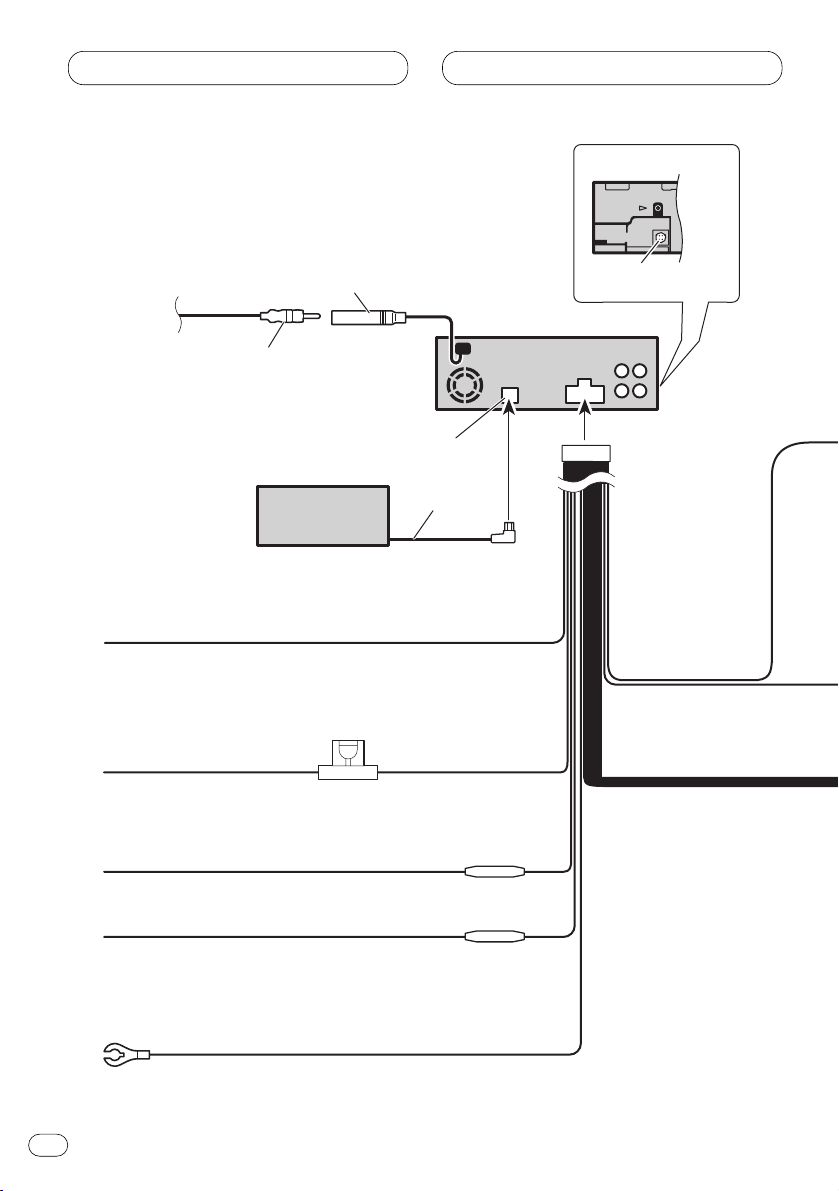
Power cable connection
Connecting the Units
En
4
Fuse holder
Fuse resistor
Fuse resistor
Yellow
To terminal always supplied
with power regardless of
ignition switch position.
Red
To electric terminal controlled
by ignition switch (12 V DC)
ON/OFF.
Black (ground)
To vehicle (metal) body.
Orange/white
To lighting switch terminal.
Yellow/black
If you use an equipment with Mute function, wire this
lead to the Audio Mute lead on the equipment. If not,
keep the Audio Mute lead free of any connections.
IP-BUS cable
This product
Antenna jack
IP-BUS input (Blue)
Multi-CD player
(sold separately)
Car Antenna plug
Optical input
(Refer to pages8–9.)
Page 5
Connecting the Units
En
5
English
Español
Deutsch
Français
Italiano
Nederlands
Blue/white
To system control terminal of the power amp
or Auto-antenna relay control terminal
(max. 300 mA 12 V DC).
White
White/black
Gray
Gray/black
Green
Green/black
Violet
Violet/black
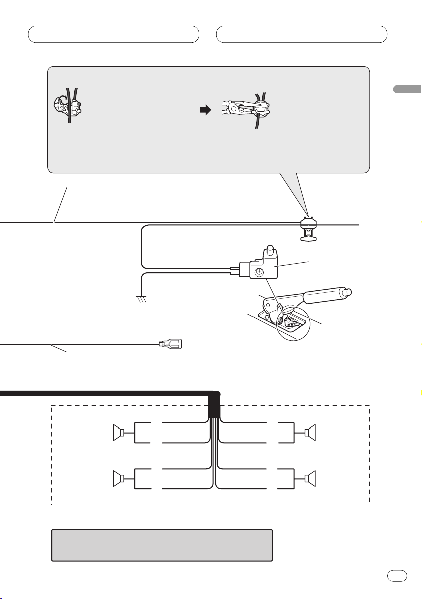
Front speaker
Rear speaker
Front speaker
Rear speaker
Left Right
With a 2 speaker system, do not connect anything
to the speaker leads that are not connected to speakers.
+
≠
+
≠
+
≠
+
≠
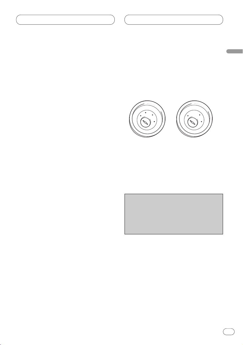
Light green
Used to detect the ON/OFF status of the parking brake.
This lead must be connected to the power supply side of the
parking brake switch.
Power supply side
Ground side
Note
• The position of the parking brake switch depends
on the vehicle model. For details, consult the
vehicle Owner’s Manual or dealer.
Connection method
Clamp the lead.1. 2. Clamp firmly with
needle-nosed
pliers.
When you connect separately sold multi-channel processor
(DEQ-P7650) to this unit, do not connect anything to the
speaker leads and system remote control (blue/white).
Parking brake
switch
Page 6
Connecting the Units
En
6
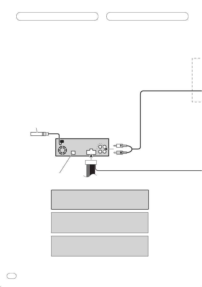
System remote control
Subwoofer output
or non fading output
Note
Change the initial setting of this product (refer to the
Operation Manual). The subwoofer output of this unit
is monaural.
Note
When you connect DEQ-P7650 to this unit, separately
sold power amp must be connected to DEQ-P7650.
This product
Antenna jack
(Refer to page 4.)
IP-BUS input (Blue)
(Refer to page 4.)
When you connect separately sold multi-channel
processor (DEQ-P7650) to this unit, do not connect
anything to the speaker leads and system remote
control (blue/white).
Connecting to separately sold power amp
Page 7
Connecting the Units
En
7
English
Español
Deutsch
Français
Italiano
Nederlands
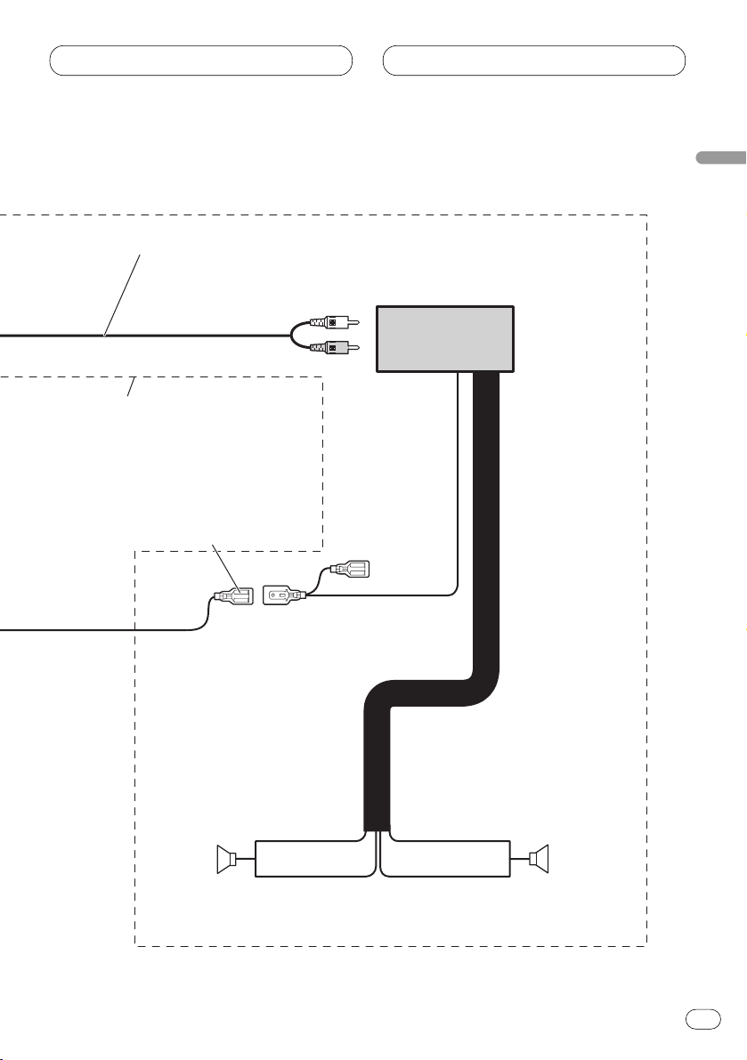
Perform these connections when
using the optional amplifier.
Blue/white
To system control terminal of the
power amp (max. 300 mA 12 V DC).
Subwoofer
Subwoofer
Connecting cords
with RCA pin plugs
(sold separately)
Left Right
System remote control
≠
+
≠
+
Power amp
(sold separately)
Page 8
Connecting the Units
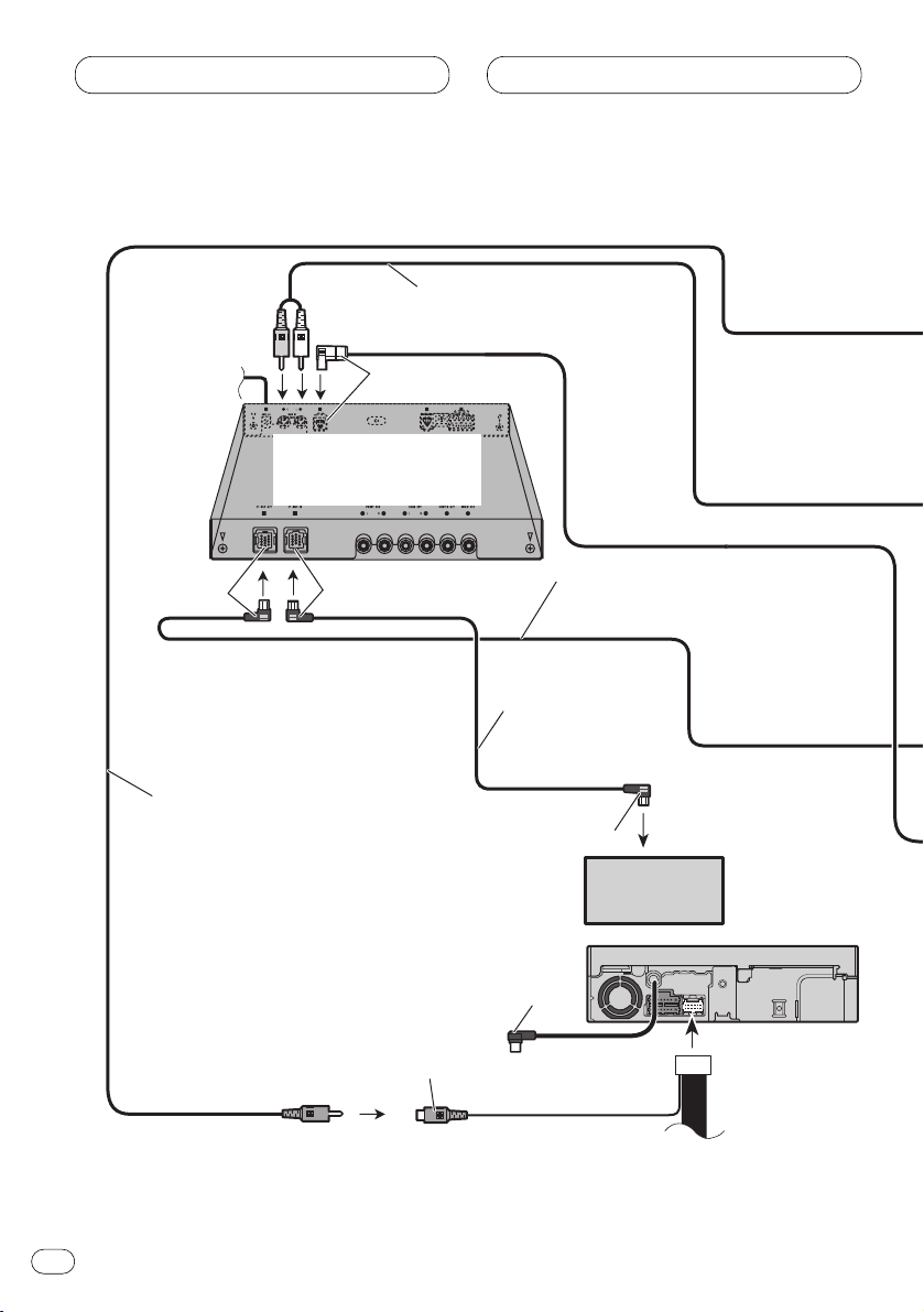
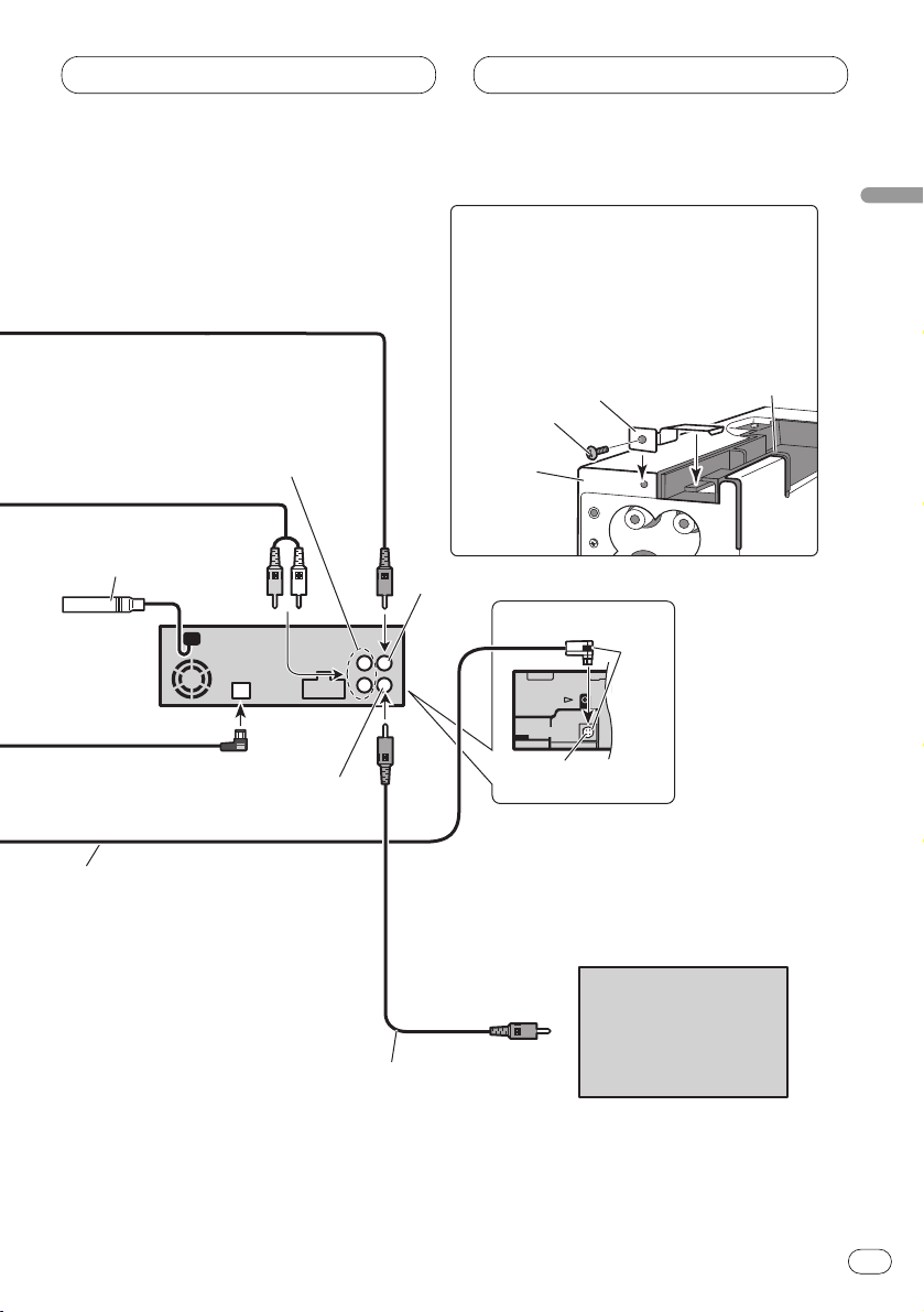
When connecting with a multi-channel processor
En
8
To video input
Yellow
RCA cable (sold separately)
AV system display
(e.g. AVX-7650)
(sold separately)
Video input
(VIDEO INPUT)
(Yellow)
IP-BUS cable
(supplied with
multi-CD player)
Black
Blue
IP-BUS cable
(supplied with
multi-channel processor)
Blue
Black
Not used
RCA cable
(supplied with multi-channel processor)
Multi-CD player
(sold separately)
Multi-channel processor
(DEQ-P7650)
(sold separately)
Page 9
Connecting the Units
En
9
English
Español
Deutsch
Français
Italiano
Nederlands
Rear video output
Optical cable
(supplied with multi-channel processor)
6m
Antenna jack
Front video output
RCA cable
(sold separately)
Subwoofer output or non fading output
Blue
This product
Black
Optical input
Display with RCA
input jacks
Optical input
Steel plate
Screw
This unit
Place the steel plate on this unit and secure
it tightly with a screw.
Note
Even if you do not connect DEQ-P7650 to
this unit right away, keep the steel plate and
a screw for the future installation.
Page 10
Connecting the Units
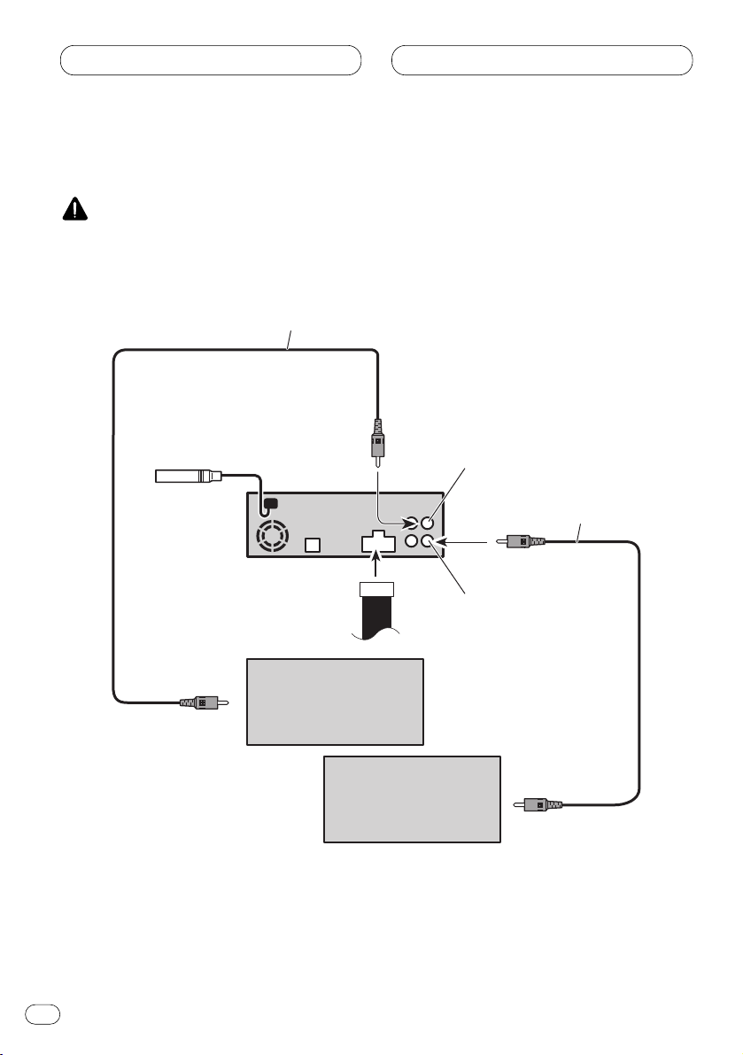
When using a display conntected to video outputs
This product’s rear video output is for connection of a display to enable passengers in the rear seats
to watch the DVD or Video CD.
WARNING
• NEVER install the rear display in a location that enables the driver to watch the DVD or Video CD
while driving.
En
10
Display with RCA
input jacks
Display with RCA
input jacks
RCA cable
(supplied)
To video input
1.5 m
This product
Rear video output
RCA cable
(sold separately)
To video input
Front video output
Page 11
Installation
En
11
English
Español
Deutsch
Français
Italiano
Nederlands
Notes
• Before making a final installation of the unit,
temporarily connect the wiring to confirm that
the connections are correct and the system
works properly.
• Use only the parts included with the unit to
ensure proper installation. The use of unauthorized parts can cause malfunctions.
• Consult with your nearest dealer if installation
requires the drilling of holes or other modifications of the vehicle.
• Install the unit where it does not get in the
driver’s way and cannot injure the passenger
if there is a sudden stop, like an emergency
stop.
• The semiconductor laser will be damaged if it
overheats, so don’t install the unit anywhere
hot — for instance, near a heater outlet.
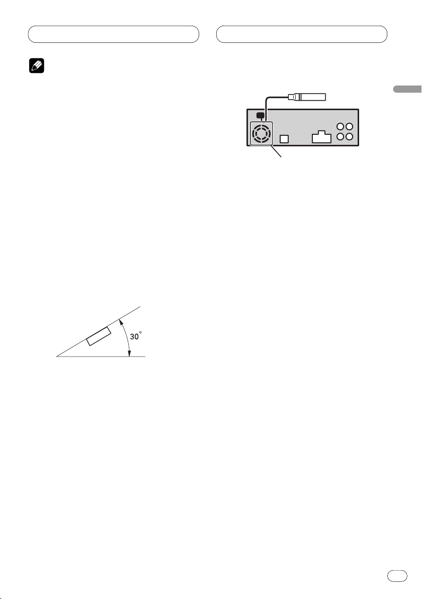
• If installation angle exceeds 30° from horizontal, the unit might not give its optimum performance.
• The cords must not cover up the area shown
in the figure below. This is necessary to allow
the amplifires to radiate freely.
• When installing, to ensure proper heat dispersal when using this unit, make sure you leave
ample space behind the rear panel and wrap
any loose cables so they are not blocking the
vents.
Do not close this area.
DIN Front/Rear-mount
This unit can be properly installed either from “Front” (conventional DIN Front-mount) or “Rear” (DIN
Rear-mount installation, utilizing threaded screw holes at the sides of unit chassis). For details, refer
to the following illustrated installation methods.
Page 12
Installation
En
12
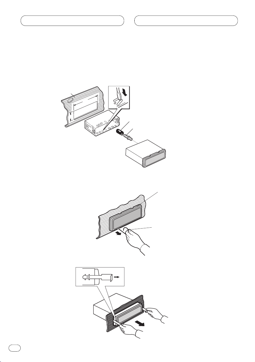
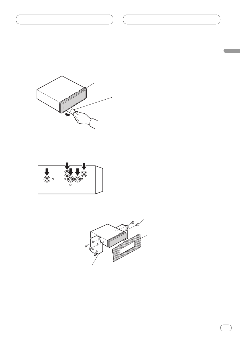
DIN Front-mount
Installation with the rubber bush
Removing the unit
Holder
After inserting the holder into the
dash-board, then select the
appropriate tabs according to the
thickness of the dash-board
material and bend them.
(Install as firmly as possible using
the top and bottom tabs. To secure,
bend the tabs 90 degrees.)
182
53
Rubber bush
Screw
Dashboard
Frame
Insert the release pin into the hole
in the bottom of the frame and pull
out to remove the frame. (When
reattaching the frame, point the
side with a groove downwards and
attach it.)
Insert the supplied extraction keys into the
unit, as shown in the figure, until they click
into place. Keeping the keys pressed against
the sides of the unit, pull the unit out.
Page 13
Installation
En
13
English
Español
Deutsch
Français
Italiano
Nederlands
DIN Rear-mount
Installation using the screw holes on the side of the unit
1. Remove the frame.
2. Fastening the unit to the factory radio mounting bracket.
Select a position where the screw holes of the
bracket and the screw holes of the head unit
become aligned (are fitted), and tighten the
screws at 2 places on each side. Use either
truss screws (5 × 8 mm) or flush surface screws
(5 × 9 mm), depending on the shape of the
screw holes in the bracket.
Frame
Insert the release pin into the hole in the
bottom of the frame and pull out to remove
the frame. (When reattaching the frame,
point the side with a groove downwards and
attach it.)
Screw
Factory radio
mounting bracket
Dashboard or Console
Page 14

Fixing the front panel
If you do not operate the removing and attaching the front panel function, use the supplied fixing
screws and holder to fix the front panel to this unit.
1. Attach the holders to both sides of the front panel.
2. Replace the front panel to the unit.
3. Flip the holders into upright positions.
4. Fix the front panel to the unit using fixing screws.
Installation
En
14
Holder
Fixing screw
Page 15

En
15
English
Español
Deutsch
Français
Italiano
Nederlands
Page 16

Conexión de las unidades
Conexión del cable de alimentación 4
Conexión al amplificador de potencia
vendido separadamente 6
Cuando conecte con un procesador
multicanal 8
Cuando utilice un presentación visual
conectado a las salidas de vídeo 10
Instalación
Montaje delantero/trasero DIN 11
Montaje delantero DIN 12
Instalación con tope de goma 12
Quitado de la unidad 12
Montaje trasero DIN 13
Instalación usando los agujeros para
tornillos ubicados en ambos costados
de la unidad 13
Colocación del panel delantero 14
ADVERTENCIA
EL CABLE VERDE CLARO DEL CONECTOR DE ALIMENTACIÓN ESTÁ
DISEÑADO PARA DETECTAR SI EL
VEHÍCULO ESTÁ ESTACIONADO Y DEBE
CONECTARSE CON EL LADO DE LA
FUENTE DE ALIMENTACIÓN DEL INTERRUPTOR DEL FRENO DE MANO. LA
CONEXIÓN O EL USO INCORRECTO DE
ESTE CABLE PUEDE INFRINGIR LAS
LEYES PERTINENTES Y OCASIONAR
LESIONES FÍSICAS O DAÑOS GRAVES.
Notes
• Esta unidad es para vehículos con batería de
12 voltios y con conexión a tierra. Antes de
instalar la unidad en un vehículo recreativo,
camioneta, o autobús, revise el voltaje de la
batería.
• Para evitar cortocircuitos en el sistema eléctrico, asegúrese de desconectar el cable de la
batería ≠ antes de comenzar con la instalación.
• Consulte con el manual del usuario para los
detalles sobre la conexión de la alimentación
de amperios y de otras unidades, luego haga
las conexiones correctamente.
• Asegure el cableado con abrazaderas de
cables o con cinta adhesiva. Para proteger el
cableado, envuélvalo con cinta adhesiva donde
éstos se apoyan sobre las piezas de metal.
• Coloque y asegure todo el cableado de tal
manera que no toque las piezas en
movimiento, tal como la palanca de cambio
de velocidades, el freno de mano, y los
pasamanos de los asientos. No coloque el
cableado en lugares que se calientan, tal
como cerca de la salida de un calefactor. Si el
material aislante del cableado se derritiera o
se gastara, habrá el peligro de un cortocircuito
del cableado a la carrocería del vehículo.
• No pase el conductor amarillo a través de un
orificio en el compartimiento del motor para
conectar a la batería. Esto dañará el material
aislante del conductor y causará un cortocircuito peligroso.
• No acorte ningún conductor. Si lo hiciera, la
protección del circuito podría fallar al funcionar cuando debería.
• Nunca alimente energía a otros equipos cortando el aislamiento del conductor de alimentación provista de la unidad y haciendo
un empalme con el conductor. La capacidad
de corriente del conductor se excederá, causando el recalentamiento.
• Cuando reemplace el fusible, asegúrese de
utilizar solamente un fusible del ratio especificado en el portafusible.
Contenido Conexión de las unidades
2
Es
Page 17

• Ya que se emplea un circuito único BPTL,
nunca coloque los cables de manera que los
conductores del altavoz estén directamente
en conexión a tierra o que el altavoz izquierdo
y derecho ≠ sean comunes.
• Los altavoces conectados a esta unidad
deben ser del tipo de alta potencia con un
régimen mínimo de 50 W y una impedancia
de 4 a 8 ohmios. La conexión de altavoces con
valores de impedancia y/o de salida diferentes
a los anotados aquí podrían causar fuego,
emisión de humo o daños a los altavoces.
• Si la toma de clavija RCA en la unidad no se
usa, retire las tapas fijadas al extremo del
conector.
• Cuando se conecta la fuente de este
producto, una señal de control se emite a
través del conductor azul/blanco. Conecte al
control remoto de sistema de un amplificador
de potencia externo o al terminal de controle
de relé de antena automática del vehículo
(máx. 300 mA 12 V CC). Si el vehículo tiene
una antena en vidrio, conecte al terminal de
suministro de energía de la antena.
• Cuando se está utilizando un amperio de
potencia externa con este sistema, asegúrese
de no conectar el conductor azul/blanco al
terminal de potencia de amperios. Asimismo,
no conecte el conductor azul/blanco al terminal de potencia de la auto-antena. Tal conexión podría causar la fuga de corriente excesiva y causar fallos de funcionamiento.
• Para evitar cortocircuitos, cubra o conductor
desconectado con cinta aislada. Aísle los
conductores de altavoz no usados sin falta.
Hay la posibilidad de cortocircuito si no se
aíslan los conductores.
• Para evitar la conexión incorrecta, el lado de
entrada del conector IP-BUS es azul, y el lado
de salida es negro. Conecte los conectores
del mismo color correctamente.
• Si se instala esta unidad en un vehículo que
no tiene una posición ACC (accesorio) en el
interruptor de encendido, el conductor rojo de
la unidad deberá conectarse al terminal
conectado con las operaciones del interruptor
de encendido ON/OFF. Si no se hace esto, la
batería del vehículo podría drenarse cuando
usted esté lejos del vehículo por varias horas.
• El conductor negro es la masa. Conecte a
masa este conductor separadamente desde la
masa de los productos de alta corriente tal
como los amplificadores de potencia.
Si conecta juntos a masa los productos y la
masa se desconecta, se crea el riesgo de
daños a los productos o de incendios.
• Los cables para esta unidad y aquéllas para
las unidades pueden ser de colores
diferentes aun si tienen la misma función.
Cuando se conecta esta unidad a otra,
refiérase a los manuales de ambas unidades
y conecte los cables que tienen la misma
función.
No en la posición ACC
Posición ACC
Es
3
English
Español
Deutsch
Français
Italiano
Nederlands
Conexión de las unidades
C
C
A
O
F
N
F
O
S
T
A
R
T
O
F
N
F
O
S
T
A
R
T
Page 18

Conexión del cable de alimentación
Conexión de las unidades
Es
4
Reproductor de
Multi-CD (en venta
por separado)
Este producto
Jack para antena
Entrada IP-Bus (Azul)
Entrada óptica (Cousulte
las páginas8–9.)
Enchufe de antena para automóvil
Cable IP-BUS
Portafusible
Resistencia
de fusible
Resistencia
de fusible
Amarillo
Al terminal con suministro
constante de electricidad,
independientemente de la posición
del interruptor de encendido.
Rojo
Al terminal de energía eléctrica controlado
por el interruptor de encendido del vehículo
(12 V de CC.) ON/OFF.
Negro (masa)
A la carrocería del veículo (parte metálica).
Anaranjado/blanco
Al terminal de interruptor de iluminación.
Amarillo/negro
Si se utiliza un equipo con función de silenciamiento, conecte este
conductor con el conductor de silenciamiento de audio en tal
equipo. De lo contrario, mantenga el conductor de silenciamiento
de audio libre de conexiones.
Page 19

Conexión de las unidades
Es
5
English
Español
Deutsch
Français
Italiano
Nederlands
+
≠
+
≠
+
≠
+
≠
1.
Verde claro
Se utiliza para detectar el estado ON/OFF del freno de mano.
Este cable debe conectarse al lado de alimentación del
interruptor del freno de mano.
Nota
• La posición del freno de estacionamiento depende del
modelo del vehículo. Para conocer detalles, consulte el
manual del propietario del vehículooasuconcesionario.
Método de conexión
Apriete el cable. 2. Apriete
firmemente con
alicates de punta
de aguja.
Interruptor del
freno de mano
Lado de alimentación
Lado de masa
Azul/blanco
Al terminal de control de sistema del amp. de
potencia o control de relé de antena
automática (máx. 300 mA de 12 V CC).
Blanco
Blanco/negro
Gris
Gris/negro
Verde
Verde/negro
Violeta
Violeta/negro
Altavoz
delantero
Altavoz
trasero
Altavoz
delantero
Altavoz
trasero
Izquierda Derecha
Con un sistema de 2 altavoces, no conecte a los conductores
de los altavoces nada que no se conecten a los altavoces.
Cuando conecte el procesador multicanal (DEQ-P7650) vendido
separadamente a esta unidad, no conecte nada a los conductores
de los altavoces y al control remoto del sistema (azul/blanco).
Page 20

Conexión de las unidades
Es
6
Control remoto de sistema
Salida de altavoz de
graves secundario o
salida sin atenuación
Nota
Cambie el ajuste inicial de este producto (refiérase
al manual de operación). La salida del altavoz de
graves secundario es monaural.
Nota
Cuando conecte el DEQ-P7650 a esta unidad, se deberá
conectar el amplificador de potencia vendido
separadamente al DEQ-P7650.
Este producto
Jack para antena
(Cousulte la página 4.)
Entrada IP-Bus (Azul)
(Cousulte la página 4.)
Cuando conecte el Procesador Multicanal (DEQ-P7650)
vendido separadamente a esta unidad, no conecte nada
a los conductores de los altavoces y al control remoto
del sistema (azul/blanco).
Conexión al amplificador de potencia vendido separadamente
Page 21

Conexión de las unidades
Es
7
English
Español
Deutsch
Français
Italiano
Nederlands
≠
+
≠
+
Altavoz secundario
Cables de conexión con
clavijás RCA
(en venta por separado)
Izquierda Derecha
Control remoto de sistema
Altavoz secundario
Amplificador de
potencia (en venta
por separado)
Lleve a cabo estas conexiones
cuando utilice el amplificador
opcional.
Azul/blanco
Al terminal de control de sistema del
amp (máx. 300 mA de 12 V CC).
Page 22

Conexión de las unidades
Cuando conecte con un procesador multicanal
Es
8
A la entrada
de vídeo
No se usa
Pantalla de
visualización de
sistema de AV
(AVX-7650, por
ejemplo)
(vendido
separadamente)
Entrada de vídeo
(VIDEO INPUT)
(Amarillo)
Cable IP-BUS
(suministrado con el
reproductor de
multi-CD)
Negro
Cable IP-BUS
(suministrado con el
procesador multicanal)
Azul
Cable RCA
(vendido separadamente)
Cable RCA
(suministrado con el procesador multicanal)
Procesador Multicanal
(DEQ-P7650)
(vendido separadamente)
Amarillo
Negro
Reproductor de
Multi-CD (en venta
por separado)
Page 23

Conexión de las unidades
Es
9
English
Español
Deutsch
Français
Italiano
Nederlands
6m
Este producto
Placa de acero
Tornillo
Esta unidad
Coloque la placa de acero en esta unidad y
fíjela firmemente con un tornillo.
Nota
Aunque no conecte el DEQ-P7650 a esta
unidad inmediatamente, almacene la placa
de acero y un tornillo para la futura
instalación.
Entrada óptica
Entrada óptica
Salida de vídeo trasera
Cable óptico
(suministrado con el
procesador multicanal)
Cable RCA
(vendido separadamente)
Salida de vídeo delantera
Presentación visual
con tomas de
entrada RCA
Salida de altavoz de graves
secundario o salida sin atenuación
Azul
Jack para antena
Negro
Page 24

Cuando utilice un presentación visual conectado a las salidas de
vídeo
La salida de vídeo trasera de este producto es para la conexión de un presentación visual para permitir que los pasajeros en los asientos traseros puedan ver el DVD o Video CD.
ADVERTENCIA
• NUNCA instale el presentación visual en un lugar que permita el motorista ver el DVD o Video CD
mientras conduce el automóvil.
Conexión de las unidades
Es
10
1,5 m
Cable RCA
(suministrado)
A la entrada
de video
Presentación visual
con tomas de
entrada RCA
Este producto
Salida de vídeo delantera
Presentación visual
con tomas de
entrada RCA
Cable RCA
(vendido separadamente)
Salida de vídeo trasera
A la entrada
de video
Page 25

Instalación
Es
11
English
Español
Deutsch
Français
Italiano
Nederlands
Notas
• Antes de finalmente instalar la unidad,
conecte el cableado temporalmente y compruebe que las conexiones están correctas e
que el sistema funciona debidamente.
• Utilice sólo las piezas que se incluyen con
esta unidad para asegurar la instalación adecuada. El uso de piezas no autorizadas podría
causar fallos de funcionamiento.
• Consulte con su distribuidor si la instalación
requiere del taladro de orificios u otras modificaciones del vehículo.
• Instale la unidad donde no alcance el espacio
del conductor, y donde no pueda dañar a los
pasajeros si sucediera un paro repentino,
como una detención de emergencia.
• El semiconductor láser se dañará si se sobrecalienta, por eso no instale la unidad en un
lugar caliente – por ejemplo, cerca de la salida de un calefactor.
• Si el ángulo de la instalación excede los 30°
del lado horizontal, la unidad podría no
brindar su óptimo funcionamiento.
• Los cordones no deben tapar el área
mostrado en la figura de abajo. Esto es necesario para permitir que los amplificadores
puedan radiar libremente.
• Cuando instale, para asegurar la dispersión
apropiada del calor cuando utilice la unidad,
asegúrese de dejar un amplio espacio detrás
del panel trasero y de enrollar cualesquiera
cables sueltos de modo que no bloqueen las
aberturas de ventilación.
Evite cerrar este área.
Montaje delantero/trasero DIN
Esta unidad quede instalarse correstamente de la “Delantera” (montaje delantero DIN convenciona)
o “Trasera” (montaje trasero DIN, utilizando los tornillos roscados en los constados del chasis de la
unidad). Para detalles, refiérase a los métodos de instalación ilustrados abajo.
Page 26

Instalación
Es
12
Montaje delantero DIN
Instalación con tope de goma
Quitado de la unidad
182
53
Marco
Inserte el pasador de liberanción en
el orificio de la parte inferior del
marco, y tire hacia afuera para
extraer el marco. (Para la fijación
del marco, apunte el lado con ranura hacia abajo.)
Inserte las herramientas de extracción suministradas en la unidad, como se indica en la
figura, hasta que se enganchen en su positión. Tire de la unidad mientras mantiene las
herramientas presionadas contra los lados
de la unidad.
Soporte
Después de insertar el soporte en la tabla de
mandos, luego seleccione las orejetas
apropiadas según el grosor del material de la
tabla de mandos y dóblelos.
(Instale lo más firme posible usando las
lengüetas superior e inferior. Para fijar,
doble las lengüetas 90 grados.)
Tope de goma
Tablero de
instrumentos
Tornillo
Page 27

Instalación
Es
13
English
Español
Deutsch
Français
Italiano
Nederlands
Montaje trasero DIN
Instalación usando los agujeros para tornillos ubicados en ambos costados de
la unidad
1 Quite el marco.
2 Fijación de la unidad a la ménsula de montaje existente.
Seleccione una posición en la que los orificios
para los tornillos del soporte y del de la unidad
principal queden alineados, y apriete los tornillos en 2 lugares de un lado. Utilice ya sea los
tornillos de fijación (5 × 8 mm) o los tornillos a
paño (5 × 9 mm), dependiendo de la forma de
los orificios de tornillo en la ménsula.
Marco
Inserte el pasador de liberanción en el orificio
de la parte inferior del marco, y tire hacia
afuera para extraer el marco. (Para la fijación
del marco, apunte el lado con ranura hacia
abajo.)
Tornillo
Ménsula de montaje
de radio existente
Tablero de instrumentos
o consola
Page 28

Colocación del panel delantero
Si no desea utilizar la función de extracción y colocación del panel delantero, utilice los tornillos de
fijación y sujetadores suministrados y fije el panel delantero a esta unidad.
1. Coloque los sujetadores en ambos lados del panel delantero.
2. Reinstale el panel delantero en la unidad.
3. Mueva los sujetadores en las posiciones verticales.
4. Fije el panel delantero a la unidad utilizando los tornillos de fijación.
Instalación
Es
14
Sujetador
Tornillos de fijación
Page 29

Es
15
English
Español
Deutsch
Français
Italiano
Nederlands
Page 30

Conexão das unidades
Conexão do cabo de alimentação 4
Quando conectar a um amplificador
de potência vendido separadamente 6
Quando conectar com um processador
multicanal 8
Quando utilizar um monitor conectado as
saídas de vídeo 10
Instalação
Montagem dianteira/traseira DIN 11
Montagem dianteira DIN 12
Instalação com uma bucha
de borracha 12
Remoção do aparelho 12
Montagem traseira DIN 13
Instalação utilizando os orifícios de
parafuso no lado do aparelho 13
Fixação do painel frontal 14
ADVERTÊNCIA
O CONDUTOR VERDE-CLARO, NO
CONECTOR DE ALIMENTAÇÃO, FOI
DESENVOLVIDO PARA DETECTAR O
STATUS ESTACIONADO E DEVE SER
ACOPLADO À FONTE DE ALIMENTAÇÃO
AO LADO DO BOTÃO DO FREIO DE MÃO.
A CONEXÃO OU O USO INADEQUADO
DESSE CONDUTOR PODE VIOLAR A LEI
APLICÁVEL E CAUSAR SÉRIOS
ACIDENTES OU DANOS.
Notes
• Este aparelho foi concebido para veículos com
uma bateria de 12 Volts e conexão à terra negativa. Antes de instalar o aparelho num veículo
recreativo, caminhão ou ônibus, verifique a
voltagem da bateria.
• Para evitar curto-circuitos no sistema elétrico,
certifique-se de desconectar o cabo ≠ da
bateria antes de iniciar a instalação.
• Consulte o manual do proprietário para maiores
detalhes sobre como conectar um amplificador de
potência e as outras unidades, e faça as conexões
corretamente.
• Prenda os fios com braçadeiras de cabo ou fita
adesiva. Para proteger os fios, enrole fita adesiva
em volta deles onde eles fiquem contra partes
metálicas.
• Encaminhe e segure todos os fios de modo
que não toquem em partes móveis, tais como a
alavanca de mudanças de marcha, alavanca
do freio de estacionamento e trilhos dos assentos. Não encaminhe os fios em lugares que
ficam muito quentes, tais como perto da saída
do aquecedor. Se o isolamento dos fios derreter-se ou cortar-se, há o perigo de curtocircuito com a carroçaria do veículo.
• Não passe o fio amarelo através do orifício no
compartimento do motor para conectá-lo à
bateria. Isso danificará o isolamento do fio e
causará um curto-circuito muito perigoso.
• Não deixe os fios entrarem em curto-circuito. Se
isso ocorrer, o circuito de proteção poderá não
funcionar.
• Nunca forneça energia a outros equipamentos
cortando o isolamento do fio de alimentação do
componente e fazendo uma emenda. A capacidade de corrente do fio será excedida, causando
um sobreaquecimento.
• Ao substituir o fusível, certifique-se de utilizar
somente um fusível com a potência nominal
especificada no porta-fusíveis.
Sumário Conexão das unidades
2
Ptbr
Page 31

Ptbr
3
English
Español
Português (B)
Français
Português (B)
Nederlands
Conexão das unidades
• Como se emprega um único circuito BPTL,
nunca faça a instalação elétrica de modo que
os fios dos alto-falantes fiquem diretamente
conectados à terra nem que os fios esquerdo
e direito ≠ dos alto-falantes fiquem em
comum.
• Os alto-falantes conectados a este aparelho
devem ser do tipo de alta potência com uma
potência nominal mínima de 50 W e uma
impedância de 4 a 8 ohms. Conectar alto-falantes
com valores de saída e/ou impedância diferentes
dos especificados pode causar o fogo, emissão de
fumaça ou danos aos alto-falantes.
• Se o jaque de pino RCA no componente não
será utilizado, não retire as tampas anexadas
ao extremo do conector.
• Quando se conecta a fonte deste produto, um
sinal de controle é emitido através do condutor
azul/branco. Conecte ao controle remoto de
sistema de um amplificador de potência externo
ou ao terminal de controle de relé de antena
automática do veículo. (Máx. 300 mA, 12 V CC.)
Se o veículo tem uma antena incorporada em
vidro, conecte ao terminal de fornecimento de
energia da antena.
• Ao utilizar um amplificador de potência
externo com este sistema, certifique-se de
não conectar o fio azul/branco do terminal de
potência do amplificador. Do mesmo modo,
não conecte o fio azul/branco do terminal de
potência da antena automática. Tal conexão
poderia causar uma drenagem de corrente
excessiva e um conseqüente mau funcionamento.
• Para evitar um curto-circuito, cubra o condutor desconectado com fita isolante. Isole os
condutores de alto-falante não usados sem
falta. Há a possibilidade de curto-circuito se
os condutores não forem isolados.
• Para evitar uma conexão incorreta, o lado de
entrada do conector IP-BUS é azul, e o lado de
saída é preto. Conecte os conectores com as
mesmas cores corretamente.
• Se este componente for instalado num
veículo não equipado com uma posição ACC
(acessório) na chave de ignição, o fio
vermelho do componente deve ser conectado
ao terminal acoplado com as operações de
ligar/desligar da chave de ignição. Se isso não
for feito, a bateria do veículo pode descarregar-se quando você ficar fora do veículo
durante várias horas.
• O cabo preto é para a terra. Aterre este cabo
separadamente da terra de produtos de corrente alta como amplificadores de potência.
Se você ligar aterrar os produtos juntos e a
terra for desligada, haverá o risco de danos
aos produtos ou incêndio.
• Os cabos para este aparelho e os de outros
componentes podem ter cores diferentes,
mesmo que tenham a mesma função.
Quando conectar este aparelho a um outro
aparelho, consulte os manuais de ambos os
aparelhos e conecte os cabos que tenham a
mesma função.
Sem posição ACCPosição ACC
C
C
A
O
F
N
F
O
S
T
A
R
T
O
F
N
F
O
S
T
A
R
T
Page 32

Conexão do cabo de alimentação
Conexão das unidades
Ptbr
4
Entrada IP-BUS (Azul)
Este produto
Cabo IP-BUS
Jaque para antena
Entrada ótico (Refira-se
as páginas8–9.)
Multi-CD player
(vendido
separadamente)
Plugue de antena
para automóvel
Amarelo
Ao terminal sempre fornecido
com energia
independentemente da
posição da chave de ignição.
Porta-fusíveis
Vermelho
Ao terminal controlado pelo ligar/desligar
da chave de ignição (12 V CC).
Preto (terra)
À carroçaria (metal) do veículo.
Laranja/branco
Ao terminal do interruptor
de iluminação.
Amarelo/preto
Se você utilizar um equipamento com uma função de
emudecimento (Mute), conecte este fio com o fio Audio Mute
de tal equipamento. Caso contrário, deixe o fio Audio Mute
livre de qualquer conexão.
Resistor de fusível
Resistor de fusível
Page 33

Conexão das unidades
Ptbr
5
English
Español
Português (B)
Français
Português (B)
Nederlands
+
≠
+
≠
+
≠
+
≠
1. 2.
Método de conexão
Prenda o fio. Prenda
firmemente com
alicate de bico
fino.
Nota
• A posição do interruptor do freio de mão depende do modelo
do veículo. Para maiores detalhes, consulte o manual do
proprietário do veículo ou revendedor.
Verde claro
Usado para detectar o estado de ligado/desligado do freio de
mão. Este fio deve ser conectado ao lado de alimentação do
interruptor do freio de mão.
Azul/branco
Ao terminal de controle do sistema do amplificador
de potência ou terminal de controle de relé de antena
automática (máx. 300 mA 12 V CC).
Interruptor do
freio de mão
Lado de alimentação
Lado de terra
Com um sistema de 2 alto-falantes, não conecte nada aos fios
de alto-falante que não estão conectados a alto-falantes.
Branco
Branco/preto
Cinza
Cinza/preto
Verde
Verde/preto
Violeta
Violeta/preto
Alto-falante
dianteiro
Alto-falante
traseiro
Alto-falante
dianteiro
Alto-falante
traseiro
Esquerda Direita
Quando conectar um processador multicanal vendido
separadamente (DEQ-P7650) a este componente, não conecte nada
aos fios de alto-falante e controle remoto do sistema (azul/branco).
Page 34

Conexão das unidades
Ptbr
6
Este produto
Saída de subwoofer
ou saída sem atenuação
Controle remoto de sistema
Entrada IP-BUS (Azul)
(Refira-se à página 4.)
Jaque para antena
(Refira-se à página 4.)
Nota
Altere a definição inicial deste produto (refira-se
ao manual de instruções).
A saída de subwoofer deste componente é monofônica.
Nota
Quando conectar o DEQ-P7650 a este componente,
o amplificador de potência vendido separadamente
deve ser conectado ao DEQ-P7650.
Quando conectar um processador multicanal
vendido separadamente (DEQ-P7650) a este
componente, não conecte nada aos fios de altofalante e controle remoto do sistema (azul/branco).
Quando conectar a um amplificador de potência vendido
separadamente
Page 35

Conexão das unidades
Ptbr
7
English
Español
Português (B)
Français
Português (B)
Nederlands
≠
+
≠
+
Amplificador de
potência (vendido
separadamente)
Subwoofer
Subwoofer
Azul/branco
Ao terminal de controle do sistema do
amplificador de potência (máx. 300 mA
12 V CC).
Cabos RCA
(vendido separadamente)
Controle remoto de sistema
Esquerda
Direita
Realize estas conexões quando
utilizar o amplificador opcional.
Page 36

Conexão das unidades
Quando conectar com um processador multicanal
Ptbr
8
Não usado.
Preto
Cabo IP-BUS
(fornecido com o processador multicanal)
Cabo RCA
(fornecido com o processador multicanal)
Cabo IP-BUS
(fornecido com
o multi-CD player)
Preto
Multi-CD player
(vendido
separadamente)
À entrada de vídeo
Cabo RCA
(vendido separadamente)
Processador multicanal
(DEQ-P7650)
(vendido separadamente)
Monitor do
sistema de AV
(por exemplo,
AVX-7650)
(vendido
separadamente)
Entrada de vídeo
(VIDEO INPUT)
(Amarelo)
Amarelo
Não usado
Azul
Azul
Page 37

Conexão das unidades
Ptbr
9
English
Español
Português (B)
Français
Português (B)
Nederlands
6m
Este produto
Monitor com
entrada RCA
Preto
Cabo ótico
(fornecido com o
processador multicanal)
Saída de subwoofer ou saída
sem atenuação
Cabo RCA
(vendido separadamente)
Coloque a placa de aço neste aparelho e
fixe-a firmemente com um parafuso.
Nota
Mesmo que não conecte o DEQ-P7650 a este
aparelho imediatamente, guarde a placa de
aço e um parafuso para a futura instalação.
Jaque para antena
Entrada ótico
Entrada ótico
Saída de vídeo frontal
Este aparelho
Placa de aço
Parafuso
Saída de vídeo traseira
Azul
Page 38

Conexão das unidades
Quando utilizar um monitor conectado as saídas de vídeo
A saída de vídeo traseira deste produto é para a conexão de um monitor para permitir que os passageiros nos assentos traseiros assistam a DVD e CD de vídeo.
ADVERTÊNCIA
• NUNCA instale o monitor num local que permita que o motorista veja o DVD ou CD de vídeo
enquanto dirige o automóvel.
Ptbr
10
Este produto
Cabo RCA
(fornecido)
À entrada
de vídeo
Cabo RCA
(vendido separadamente)
À entrada
de vídeo
1,5 m
Saída de vídeo frontal
Monitor com
entrada RCA
Monitor com
entrada RCA
Saída de vídeo traseira
Page 39

Instalação
Ptbr
11
English
Español
Português (B)
Français
Português (B)
Nederlands
Notes
• Antes de realizar a instalação final do aparelho, conecte os fios temporariamente para
confirmar que as conexões estejam corretas e
que o sistema funcione apropriadamente.
• Utilize somente as peças incluídas com o
aparelho para garantir uma instalação correta. O uso de peças não autorizadas pode
causar defeitos.
• Consulte o seu revendedor mais próximo se
for necessário fazer perfurações ou outras
modificações no veículo para a instalação.
• Instale o aparelho de modo que não fique no
caminho do motorista nem onde possa
causar danos aos passageiros no caso de
uma parada repentina, como numa freada de
emergência.
• O laser de semicondutor será avariado se for
sobreaquecido. Portanto, não instale o aparelho num lugar que fique muito quente como
por exemplo, perto da saída do aquecedor.
• Se o ângulo de instalação exceder de 30°
desde a horizontal, o aparelho pode não atingir sua performance ótima.
• Os cabos não devem cobrir a área mostrada
na figura abaixo. Isso é necessário para permitir que o amplificador radie o calor livremente.
• Quando instalar, para assegurar a dispersão
apropriada do calor ao utilizar o aparelho,
certifique-se de deixar um amplo espaço atrás
do painel traseiro e de enrolar quaisquer
cabos soltos de modo que não bloqueiem as
aberturas de ventilação.
Não feche esta área.
Montagem dianteira/traseira DIN
Este aparelho pode ser instalado apropriadamente na “Dianteira” (montagem convencional dianteira
DIN) ou na “Traseira” (montagem traseira DIN, utilizando os orifícios de parafusos roscados nos
lados do chassi do aparelho). Para maiores detalhes, refira-se aos seguintes métodos de instalação
ilustrados.
Page 40

Montagem dianteira DIN
Instalação com uma bucha de borracha
Remoção do aparelho
182
53
Instalação
Ptbr
12
Sujeitador
Depois de inserir o sujeitador no painel de instrumentos, escolha as lingüetas apropriadas de
acordo com a espessura do material do painel de
instrumento, e dobre-as.(Instale o mais firme
possível usando as lingüetas superior e inferior.
Para fixar, dobre as lingüetas 90 graus.)
Bucha de borracha
Painel de instrumentos
Parafuso
Insira o pino de liberação no orifício no fundo da armação e puxe-o
para fora para remover a armação.
(Quando recolocar a armação,
aponte o lado com a ranhura para
baixo e fixe-a.)
Armação
Insira as chaves de extração fornecidas no aparelho, como mostrado na figura, até que elas se
encaixem em posição. Enquanto mantém as
chaves pressionadas contra os lados do aparelho, puxe o aparelho para fora.
Page 41

Instalação
Ptbr
13
English
Español
Português (B)
Français
Português (B)
Nederlands
Montagem traseira DIN
Instalação utilizando os orifícios de parafuso no lado do aparelho
1 Retire a armação.
2 Fixação do aparelho no suporte de montagem de rádio da fábrica.
Insira o pino de liberação no orifício no fundo
da armação e puxe-o para fora para remover a
armação.(Quando recolocar a armação, aponte
o lado com a ranhura para baixo e fixe-a.)
Armação
Escolha a posição onde os orifícios de parafusos
do suporte e os orifícios dos parafusos do componente principal fiquem alinhados (ajustados),
e aperte os parafusos em 2 lugares em cada
lado. Utilize parafusos reforçados (5
× 8 mm), ou
parafusos embutidos (5 × 9 mm), dependendo
da forma dos orifícios para os parafusos no
suporte.
Suporte de montagem
de rádio da fábric
Parafuso
Painel de instrumentos ou consolo
Page 42

Instalação
Ptbr
14
Fixação do painel frontal
Se você não utilizar a função de remover e recolocar o painel frontal, utilize os parafusos de fixação e
sujeitador fornecidos para fixar o painel frontal neste aparelho.
1. Fixe os sujeitadores em ambos os lados do painel frontal.
2. Recoloque o painel frontal neste aparelho.
3. Vire os sujeitadores para as posição verticais.
4. Fixe o painel frontal neste aparelho utilizando os parafusos de fixação.
Sujeitador
Parafuso de fixação
Page 43

Published by Pioneer Corporation.
Copyright © 2005 by Pioneer Corporation.
All rights reserved.
Publication de Pioneer Corporation.
Copyright © 2005 Pioneer Corporation.
Tous droits de reproduction et de traduction
réservés.
Printed in China
Imprimé en China
<CRD4046-A/U> RD<KMIZX> <05F00000>
PIONEER CORPORATION
4-1, MEGURO 1-CHOME, MEGURO-KU, TOKYO 153-8654, JAPAN
PIONEER ELECTRONICS (USA) INC.
P.O. Box 1540, Long Beach, California 90801-1540, U.S.A.
TEL: (800) 421-1404
PIONEER EUROPE NV
Haven 1087, Keetberglaan 1, B-9120 Melsele, Belgium
TEL: (0) 3/570.05.11
PIONEER ELECTRONICS ASIACENTRE PTE. LTD.
253 Alexandra Road, #04-01, Singapore 159936
TEL: 65-472-7555
PIONEER ELECTRONICS AUSTRALIA PTY. LTD.
178-184 Boundary Road, Braeside, Victoria 3195, Australia
TEL: (03) 9586-6300
PIONEER ELECTRONICS OF CANADA, INC.
300 Allstate Parkway, Markham, Ontario L3R OP2, Canada
TEL: 1-877-283-5901
PIONEER ELECTRONICS DE MEXICO, S.A. de C.V.
Blvd. Manuel Avila Camacho 138 10 piso
Col.Lomas de Chapultepec, Mexico, D.F. 11000
TEL: 55-9178-4270
 Loading...