

pioneer DV-610 SERVICE MANUAL

SERVICE MANUAL
V1.0
SPECIFICATION
Power requirement 12 V DC car battery
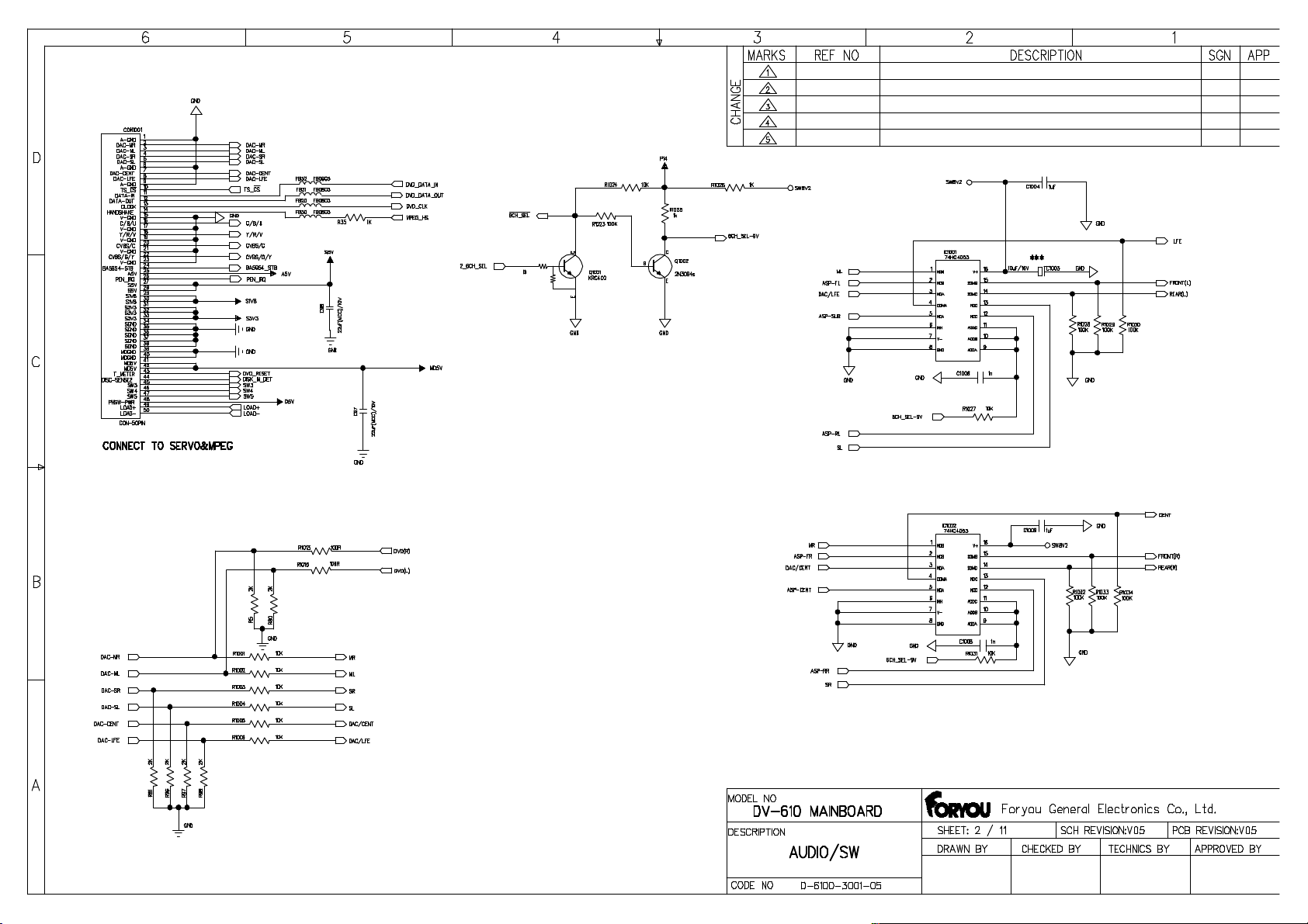
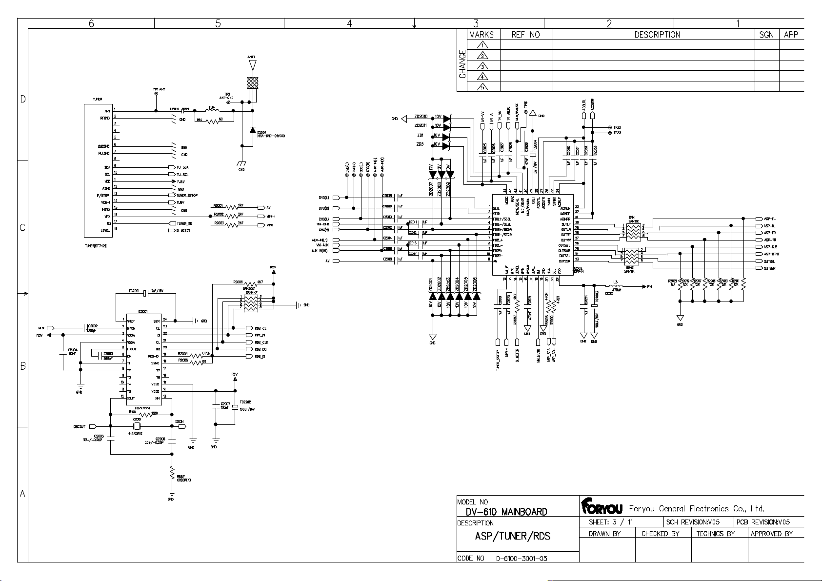
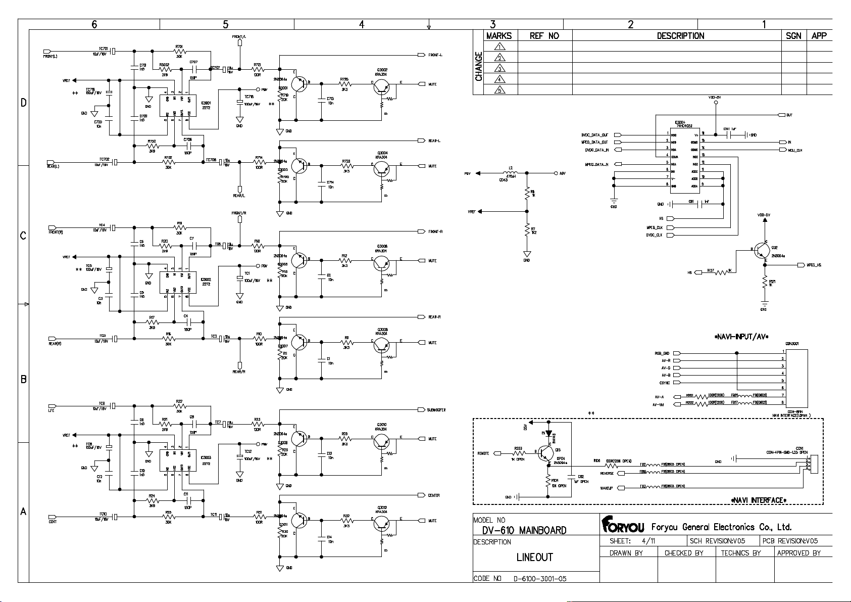
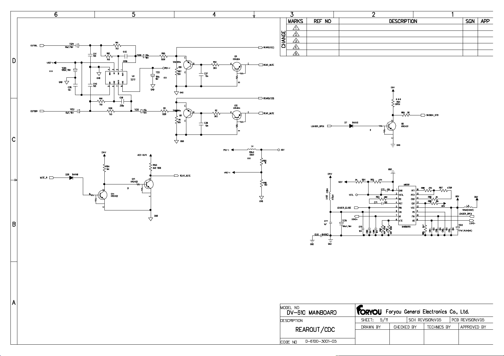
DV-610
(negative earth)
Operating temperature -20℃~+70℃
Dimensions Approx 178mm×180mm×100mm (W/D/H)
Storage temperature -30℃ ~ +80℃
Operational humidity 45%~80%RH
Atmosphere pressure 860mbar~1060mbar

PRODUCT SAFETY SERVICING GUIDELINES FOR VIDEO PRODUCTS
2
CAUTION: DO NOT ATTEMPT TO MODIFY THIS PRODUCT IN ANY WAY AND NEVER
PERFORM CUSTOMIZED INSTALLATIONS WITHOUT MANUFACTURER'S APPROVAL.
NAUTHORIZED MODIFICATIONS WILL NOT ONLY VOID THE WARRANTY, BUT MAY LEAD TO
YOUR BEING LIABLE FOR ANY RESULTING PROPERTY DAMAGE OR USER INJURY.
SERVICE WORK SHOULD BE PERFORMED ONLY AFTER YOU ARE THOROUGHLY FAMILIAR
WITH ALL OF THE FOLLOWING SAFETY CHECKS AND SERVICING GUIDELINES. TO DO
OTHERWISE, INCREASES THE RISK OF POTENTIAL HAZARDS AND INJURY TO THE USER.
.WHILE SERVICING, USE AN ISOLATION TRANSFORMER FOR PROTECTION FROM A.C. LINE
SHOCK.
SAFETY CHECKS
AFTER THE ORIGINAL SERVICE PROBLEM HAS BEEN CORRECTED, A CHECK SHOULD BE
MADE OF THE FOLLOWING.
SUBJECT: FIRE & SHOCK HAZARD
1. BE SURE THAT ALL COMPONENTS ARE POSITIONED IN SUCH A WAY AS TO AVOID
POSSIBILITY OF ADJACENT COMPONENT SHORTS. THIS IS ESPECIALLY IMPORTANT ON
THOSE MODULES WITCH ARE TRANSPORTED TO AND FROM THE REPAIR SHOP.
2. NEVER RELEASE A REPAIR UNLESS ALL PROTECTIVE DEVICES SUCH AS INSULATORS,
BARRIERS, COVERS, SHIELDS, STRAIN RELIEFS, POWER SUPPLY CORDS, AND OTHER
HARDWARE HAVE BEEN REINSTALLED PER ORIGINAL DESIGN. BE SURE THAT THE SAFETY
PURPOSE OF THE POLARIZED LINE PLUG HAS NOT BEEN DEFEATED.
3. SOLDERING MUST BE INSPECTED TO DISCOVER POSSIBLE COLD SOLDER JOINTS,
SOLDER SPLASHES OR SHARP SOLDER POINTS. BE CERTAIN TO REMOVE ALL LOOSE
FOREIGN PARTICLES.
4. CHECK FOR PHYSICAL EVIDENCE DF DAMAGE OR DETERIORATION TO PARTS AND
COMPONENTS, FOR FRAYED LEADS AND DAMAGED INSULATION (INCLUDING A.C.
CORD), AND REPLACE IF NECESSARY FOLLOW ORIGINAL LAYOUT, LEAD LENGTH AND
DRESS.
5. NO LEAD OR COMPONENT SHOULD TOUCH A RECEIVING TUBE OR A RESISTOR RATED
AT 1 WATT OR MORE. LEAD TENSION AROUND PROTRUDING METAL SURFACES MUST BE
AVOIDED.
6. ALL CRITICAL COMPONENTS SUCH AS FUSES. FLAMEPROOF RESISTORS, CAPACITORS,
ETC. MUST BE REPLACED WITH EXACT FACTORY TYPES, DO NOT USE REPLACEMENT
COMPONENTS OTHER THAN THOSE SPECIFIED OR MAKE UNRECOMMENDED CIRCUIT
MODIFICATIONS.
7. AFTER RE-ASSEMBLY OF THE SET, ALWAYS PERFORM AN A.C. LEAKAGE TEST ON ALL
EXPOSED METALLIC PARTS OF THE CABINET, (THE CHANNEL SELECTOR KNOB, ANTENNA
TERMINALS. HANDLE AND SCREWS) TO BE SURE THE SET IS SAFE TO OPERATE WITHOUT
DANGER OF ELECTRICAL SHOCK. DO NOT USE A LINE ISOLATION TRANSFORMER DURING
THIS TEST, MAKE SURE TO USE AN A.C. VOLTMETER. HAVING 5000 OHMS PER VOLT OR
MORE SENSITIVITY, IN THE FOLLOWING MANNER; CONNECT A 1500 OHMS 10 WATT
RESISTOR, PARALLELED BY A.15 MFD. 150V A.C. TYPE CAPACITOR BETWEEN A KNOWN
GOOD EARTH GROUND (WATER PIPE, CONDUIT, ETC.) AND THE EXPOSED METALLIC PARTS,
ONE AT A TIME. MEASURE THE A.C. VOLTAGE ACROSS THE COMBINATION OF 1500 OHM
RESISTOR AND 15 MFD CAPACITOR. REVERSE THE A.C. PLUG AND REPEAT A.C. ANY
VOLTAGE MEASUREMENTS FOR EACH EXPOSED METALLIC PART. VOLTAGE MEASURED
MUST NOT EXCEED 75 VOLTS R.M.S. THIS CORRESPONDS TO 0.5 MILLIAMP A.C. ANY
VALUE EXCEEDING THIS LIMIT CONSTITUTES A POTENTIAL SHOCK HAZARD AND MUST BE
CORRECTED IMMEDIATELY.
GOOD EARTH GROUND
SUCH AS THE WATER
PIPE, CONDUIT, ETC.
SUBJECT GRAPHIC SYMBOLS
PLACE THIS PROBE
ON EACH EXPOSED
METAL PART
SUBJECT: X-RADIATION
1.BE SURE PROCEDURES AND INSTRUCTIONS TO ALL SERVICE PERSONNEL COVER THE
SUBJECT OF X-RADIATION. THE ONLY POTENTIAL SOURCE OF X-RAYS IN CURRENT T.V.
RECEIVERS IS THE PICTURE TUBE. HOWEVER, THIS TUBE DOES NOT EMIT X-RYS WHEN THE
HIGH VOLTAGE IS AT THE FACTORY SPECIFIED LEVEL. THE PROPER VALUE IS GIVEN IN THE
APPLICABLE SCHEMATIC. OPERATION AT HIGHER VOLTAGES MAY CAUSE A FAILURE OF
THE PICTURE TUBE OR HIGH VOLTAGE SUPPLY AND, UNDER CERTAIN CIRCUMSTANCES,
MAY PRODUCE RADIATION IN EXCESS OF DESIRABLE LEVELS.
2. ONLY FACTORY SPECIFIED C.R.T ANODE CONNECTORS MUST BE USED
DEGAUSSING SHIELDS ALSO SERVE AS AN X-RAY SHIELD IN COLOR SETS,
ALWAYS RE-INSTALL THEM.
3. IT IS ESSENTIAL THAT SERVICE PERSONNEL HAVE AVAILABLE AN ACCURATE AND
RELIABLE HIGH VOLTAGE METER. THE CALIBRATION OF THE METER SHOULD BE CHECKED
PERIODICALLY AGAINST A REFERENCE STANDARD, SUCH AS THE ONE AVAILABLE AT YOUR
DISTRIBUTOR.
4. WHEN THE HIGH VOLTAGE CIRCUITRY IS OPERATING PROPERLY, THERE IS NO
POSSIBILITY OF AN ACCURATE AND RELIABLE HIGH VOLTAGE METER. THE CALIBRATION OF
THE METER SHOULD BE CHECKED PERIODICALLY AGAINST A REFERENCE STANDARD,
SUCH AS THE ONE AVAILABLE AT YOUR DISTRIBUTOR.
5. WHEN TROUBLESHOOTING AND MAKING TEST MEASUREMENTS IN A PRODUCT WITH A
PROBLEM OF EXCESSIVE HIGH VOLTAGE AVOID BEING UNNECESSARILY CLOSE TO THE
PICTURE TUBE AND THE HIGH VOLTAGE SUPPLY DO NOT OPERATE THE PRODUCT LONGER
THAN IT IS NECESSARY TO LOCATE THE CAUSE OF EXCESSIVE VOLTAGE.
6. REFER TO HV. B+ AND SHUTDOWN ADJUSTMENT PROCEDURES DESCRIBED IN THE
APPROPRIATE SCHEMATIC AND DIAGRAMS(WHERE USED).
SUBJECT: IMPLOSION
1. ALL DIRECT VIEWED PICTURE TUBES ARE EQUIPPED WITH AN INTEGRAL IMPLOSION
PROTECTION SYSTEM, BUT CARE SHOULD BE TAKEN TO AVOID DAMAGE DURING
INSTALLATION, AVOID SCRATCHING THE TUBE. IF SCRATCHED REPLACE IT.
2. USE ONLY RECOMMENDED FACTORY REPLACEMENT TUBES.
SUBJECT: TIPS ON PROPER INSTALLATION
1. NEVER INSTALL ANY PRODUCT IN A CLOSED-IN RECESS. CUBBYHOLE OR CLOSELY
FITTING SHELF SPACE, OVER OR CLOSE TO HEAT DUCT, OR IN THE PATH OF HEATED AIR
FLOW.
2. AVOID CONDITIONS OF HIGH HUMIDITY SUCH AS: OUTDOOR PATIO INSTALLATIONS
WHERE DEW IS A FACTOR, NEAR STEAM RADIATORS WHERE STEAM LEAKAGE IS A FACTOR,
ETC.
3. AVOID PLACEMENT WHERE DRAPERIES MAY OBSTRUCT REAR VENTING. THE CUSTOMER
SHOULD ALSO AVOID THE USE OF DECORATIVE. SCARVES OR OTHER COVERINGS WHICH
MIGHT OBSTRUCT VENTILATION.
4. WALL AND SHELF MOUNTED INSTALLATIONS USING A COMMERCIAL MOUNTING KIT,
MUST FOLLOW THE FACTORY APPROVED MOUNTING INSTRUCTIONS. A PRODUCT
MOUNTED TO A SHELF OR PLATFORM MUST RETAIN ITS ORIGINAL FEET (OR THE
EQUIVALENT THICKNESS IN SPACERS). TO PROVIDE ADEQUATE AIR FLOW ACROSS THE
BOTTOM. BOLTS OR SCREWS USED FOR FASTENERS MUST NOT TOUCH ANY PARTS OR
WIRING. PERFORM LEAKAGE TEST ON CUSTOMIZED INSTALLATIONS.
5. CAUTION CUSTOMERS AGAINST THE MOUNTING OF A PRODUCT ON SLOPING SHELF
OR A TILTED POSITION, UNLESS THE PRODUCT IS PROPERLY SECURED.
6. A PRODUCT ON A ROLL-ABOUT CART SHOULD BE STABLE ON ITS MOUNTING TO THE
CART CAUTION THE CUSTOMER ON THE HAZARDS OF TRYING TO ROLL A CART WITH
SMALL CASTERS ACROSS THRESHOLDS OR DEEP PILE CARPETS.
7. CAUTION CUSTOMERS AGAINST THE USE OF A CART OR STAND WHICH HAS NOT BEEN
LISTED BY UNDERWRITERS LABORATORIES, INC. FOR USE WITH THEIR SPECIFIC MODEL OF
TELEVISION RECEIVER OR GENERICALLY APPROVED FOR USE WITH TV'S OF THE SAME OR
LARGER SCREEN SIZE.
8. CAUTION CUSTOMERS AGAINST THE USE OF EXTENSION CORDS. EXPLAIN THAT A
FOREST OF EXTENSIONS SPROUTING FROM A SINGLE OUTLET CAN LEAD TO DISASTROUS
CONSEQUENCES TO HOME AND FAMILY.
The lightening flash with arrowhead symbol, within an equilateral
triangle, is intended to alert the user to the presence of uninsulated
"dangerous voltage" within the product's enclosure that may be of
sufficient magnitude to constitute a risk of electric shock to persons.
The exclamation point within an equilateral triangle is intended to alert
the user to the presence of important operating and maintenance
(servicing) instructions in the literature accompanying the appliance.

SERVICING PRECAUTIONS
3
CAUTION : Before servicing the DVD covered by this service
data and its supplements and ADDENDUMS, read and
follow the SAFETY PRECAUTIONS NOTE : if unforeseen
circumstances create conflict between the following
servicing precautions and any of the safety precautions in
this publications, always follow the safety Precautions.
Remember Safety First:
General Servicing Precautions
1. Always unplug the DVD DC power cord from the DC
power source before:
(1) Removing or reinstalling any component, circuit board,
module, or any other assembly.
(2) Disconnection or reconnecting any internal electrical
plug or other electrical connection.
Caution : A wrong part substitution or incorrect polarity
installation of electrolytic capacitors may result in an
explosion hazard.
2. Do not spray chemicals on or near this DVD or any of its
assemblies.
3. Unless specified otherwise in this service data, clean
electrical contacts by applying an appropriate contact
cleaning solution to the contacts with a pipe cleaner,
cotton-tipped swab, or comparable soft applicator.
Unless specified otherwise in this service data, lubrication
of contacts is not required.
Electrostatically Sensitive (ES) Devices
Some semiconductor (solid state) devices can be
damaged easily by static electricity. Such components
commonly are called Electrostatically Sensitive (ES) Devices.
Examples of typical ES devices are integrated circuits and
some field effect transistors and semiconductor chip
components. The following techniques should be used to
help reduce the incidence of component damage
caused by static electricity.
1. Immediately before handling any emiconductor
component or semiconductor-equipped assembly, drain
off any electrostatic charge on your body by touching a
known earth ground. Alternatively, obtain and wear a
commercially available discharging wrist strap device,
which should be removed for potential shock reasons
prior to applying power to the unit under test.
2. After removing an electrical assembly equipped with ES
devices, place the assembly on a conductive surface
such as aluminum toil, to prevent electrostatic charge
buildup or exposure of the assembly.
3. Use only a GROUNDED-tip soldering iron to solder or
unsolder ES devices.
4. Use only an anti-static solder removal device. Some
solder removal devices not classified a "anti-static" can
generate electrical charges sufficient to damage ES
devices.
4. Do not defeat any plug/socket B+ voltage interlocks with
which instruments covered by this service manual might
be equipped.
5. Do not apply AC power to this DVD and/or any of its
electrical assemblies unless all solid-state device heat
sinks are correctly installed
.
6. Always connect test instrument ground lead to the
appropriate ground before connection the test
instrument positive lead. Always remove the test
instrument ground lead last.
Insulation Checking Procedure
Disconnect the attachment plug trom the AC outlet and
turn the power on. Connect an insulation resistance
meter(500V) to the blades of the attachment plug. The
insulation resistance between each blade of the
attachment plug and accessible conductive parts (Note 1)
should be more than 1M ohm.
Note 1 : Accessible Conductive Parts including Metal
panels, input terminals, Earphone jacks, etc.
5. Do not use freon-propelled chemicals. These can
generate electrical charge sufficient to damage ES
devices.
6. Do not remove a replacement ES device from its
protective package until immediately before you are
ready to install it. (Most replacement ES devices are
packaged with leads electrically shorted together by
conductive foam, aluminum foil, or comparable
conductive material.)
7. Immediately before removing the protective material
from the leads of a replacement ES device, touch the
protective material to the chassis or circuit assembly into
which the device will be installed.
Caution : Be sure no power is applied to the chassis or
circuit, and observe all other safety precautions.
8. Minimize bodily motions when handling unpackaged
replacement ES devices. (Normally harmless motion
such as the brushing together of your clothes fabric or
the lifting of your foot from a carpeted floor can
generate static electricity sufficient to damage an ES
device.)

The Service Guide of DV-610
1. The Unit can not be powered on.
1) Check whether there is a fuse in the fi lter box of power line or whether the fuse
has been blown.
2) If the unit can not be powered on yet, change the power line.
3) If the unit still can not be powered on, you should check whether the reset button
is pushed down by the front panel.
4) If the unit can not be powered on yet after the above operation, you should
change the mainboard part.
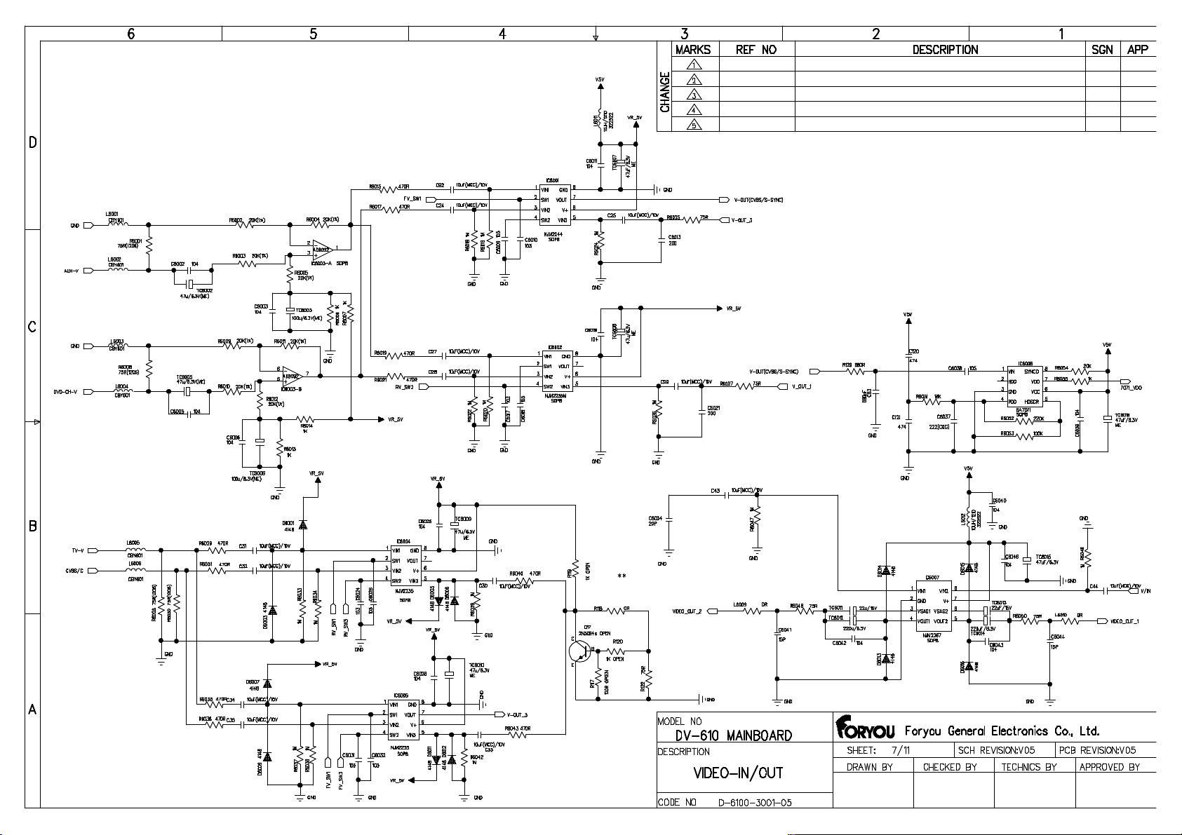
2. No display
1) Check whether the connection of video output is right.
2) If there is no display yet, change the video output line.
3) If there is no display yet, change the loader part.
4) If there is no display after the above operation, you should change the
mainboard part.
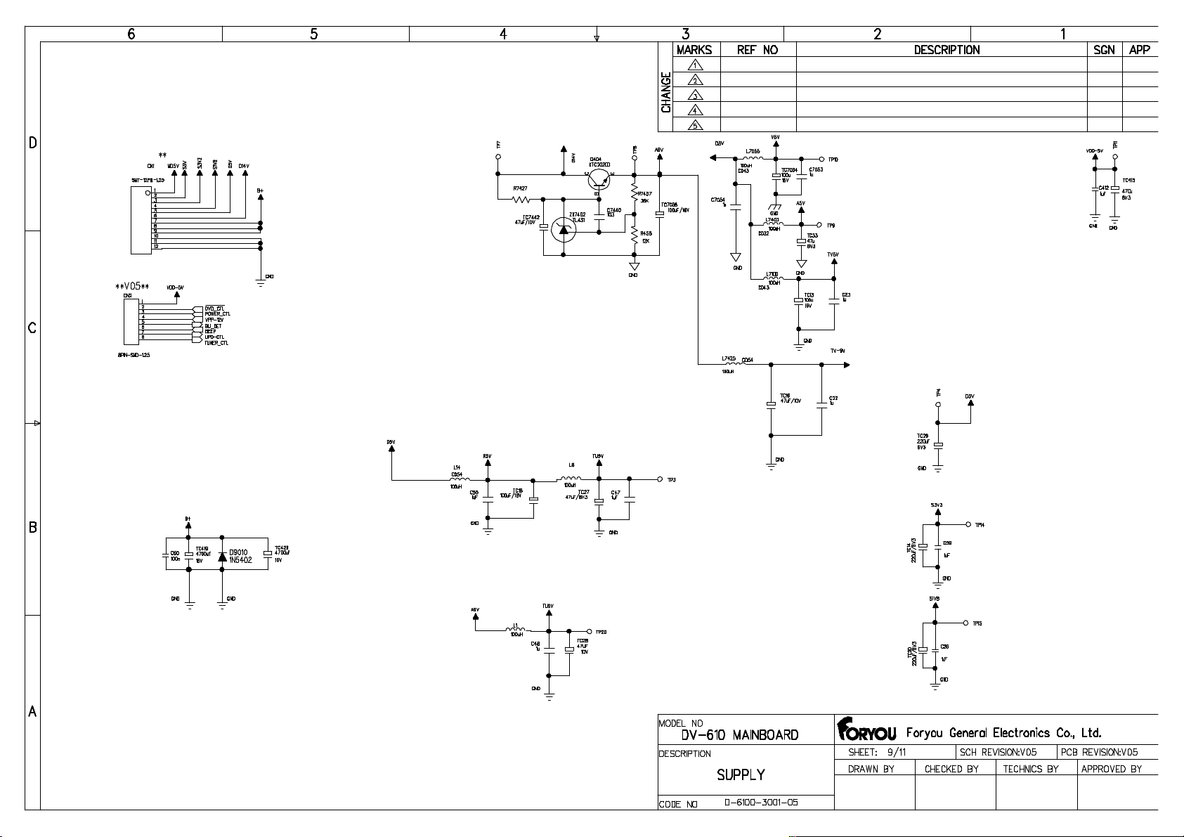
3. Shut down automatically
1) Check whether the power supply is accord with the specification.
2) Check whether the fuse in the filter box of the power line has been blown.
3) Check whether the ACC is connected to the high level (The ACC is connected to
the battery generally).
4) If the trouble is still not solved yet, check the connection between the front panel
and the mainboard. If necessary, change the connector.
5) If the unit shuts down automatically yet after the above operation, you should
change the mainboard part.
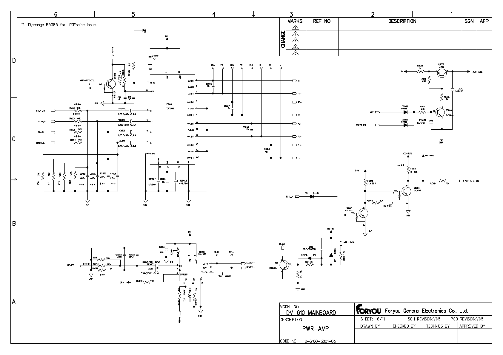
4. No audio output
1) Check whether the MUTE key is pressed.
2) Check whether the Fast Forward key or the Fast backward key is pressed.
3) Change the audio output line.
4) If there is no audio output yet, change the mainboard part.
5) If the trouble is not solved yet after the above operation, change the loader part.
5. AUX-IN function failure
1) Check whether the AUX-IN input line is available.
2) If the AUX-IN function is viod yet, change the mainboard part.
6. The fan can not work normally.
1) Check whether the power supply is turned on.
2) Check whether the power socket of the fan is connected firmly.
3) Chang a good fan.
4) If the fan can not turn yet after the above operation, chang the power supply part
4

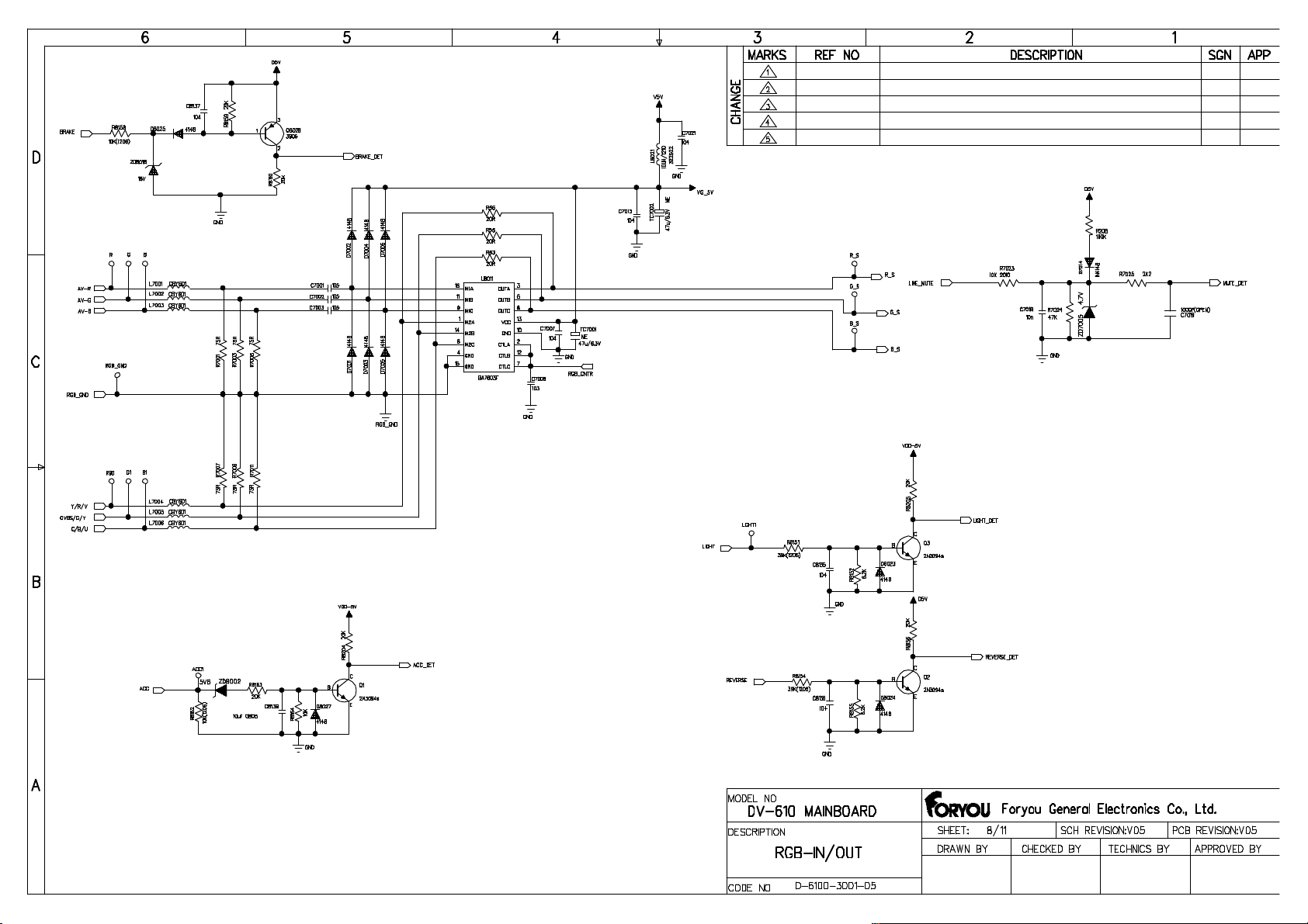
7. The color of TFT is abnormal
1) Check whether the video output of rear zone is normal.
2) If the video output of rear zone is normal, that is to say the loader work normally,
and you should change the TFT driver board.
3) If the video output of rear zone is abnormal, change the loader part.
4) If the color of TFT is abnormal yet after the above operation, change the
mainboard part.
8. White screen
1) Check the connection between the loader and the mainboard, the mainboard
and TFT part.
2) If the trouble is still not solved after the above operation, change the TFT driver
board .
9. Black screen(No display in the TFT)
1) Check the connection between the loader and the mainboard, the mainboard
and TFT part.
2) Check whether the background lights are illumed.
3) If there is no display in the TFT, change the display part.
4) If there is still no display in the TFT after the above operation, change the
mainboard part.
10. Blue screen
1) Check the connection between the loader and the mainboard, the mainboard
and TFT part, the power supply board of TFT and the TFT.
2) If the trouble still exists, chang the loader.
3) If the trouble is not solved yet, change the mainboard.
11. Key function failure
1) Check whether the key in the front panel is available.
2) Check the connection between the front panel and the mainboard. If necessary,
change the FFC connector.
3) If the key in the front panel is void, change the front panel part.
4) Check whether the key in the CCFL panel is available.
5) Check the connection between the TFT power supply board and the mainboard.
If necessary, change the FPC connector.
6) If the key in the CCFL panel is void, change the display part.
12. The TFT can not be pull back or pushed out normally
1) Check the connection between the power supply board of TFT and the motor
driver board, the power supply board of TFT and the mainboard.If necessary,
change these connectors.
2) Check whether there is any problem in machinery.
3) To confirm whether the motor work normal, change one good.
4) To confirm whether the motor driver board work normal, change one good.
5

5) If the trouble is still not solved after the above operation, change the mainboard
part.
13. Remote controller function failure
1) Check whether the key in the front panel is valid.
2) If the key in the front panel is valid,that is to say the mainboard works normally.
Check whether the battery of the remote controller is available or change
another one good.
3) If the key in the front panel is viod, you should check the connection between the
front panel and the mainboard. If necessary, change the FFC conector.
4) If the trouble is still not solved yet, change the front panel.
5) If the trouble is still not solved yet, change the mainboard part.
14. No volume display in the TFT
1) Check whether the volume button is available.
2) Check whether there is volume display in the TFT using the remoter controller to
adjust the volume.
3) If there is volume display in the TFT using the remoter controller to adjust the
volume, that is to say the display part and the mainboard part work normally, you
should change the front panel part.
4) If there is no volume display in the TFT using the remoter controller to adjust the
volume, change the mainboard part.
5) If the trouble is still not solved yet, change the display part.
15. The picture of playback is not fluent
1) Check whether the disc is dirty, scratched or deformed.
2) Check whether the lens of pick-up is dirty and clean it.
3) If the picture of playback is not fluent yet, you should change the loader part.
16. Loading failure
1) Check whether the disc you want playback is accord with the specification.
2) Check the connection between the pick-up mechanism and the servo&MPEG
board. If necessary, chang the loader part.
17. Can not insert one disc
1) Check whether there is another disc in the unit.
2) Check the connection between the loader part and the mainboard part. If
necessary, change the connector.
3) If the trouble still exists, change the loader part.
4) If the trouble is still not solved after the above operation, change the mainboard
part.
18. Can not eject the disc
1) Check the connection between the front panel and the mainboard.
2) Check the connection between the mainboard and the loader.
3) If the trouble is still not be solved, chang the loader.
6

4) If the trouble is still not be solved after changing the loader, change the
mainboard.
19. Eject the disc automatically
1) Check the connection between the loader and the mainboard.
2) If the trouble still exists, change the loader.
3) If the trouble is not solved yet after changing the loader, you should change the
mainboard.
20. Radio can not work normally
1) Make sure whether the Tuner is welded firmly.
2) Change another good Tuner.
3) If the trouble is still not be solved after changing the Tuner, change the
mainboard.
21. TV can not work normally
1) Make sure whether the TV Tuner is welded firmly.
2) Change another good TV board.
3) If the trouble is still not be solved after changing the TV board, change the
mainboard.
7
Addenda
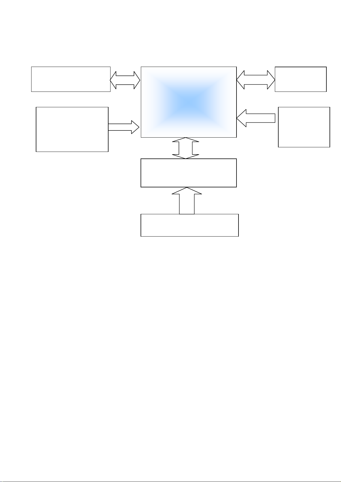
The board connection diagram of DV-610ADM
MPEG &SERVO
MainBoard
7PIN
Motor
POWER
SUPPLY
50
TFT DRIVER
14
PIN
Front Key
DV-610 Board Connection
Eject
Key
8
 Loading...