

Pioneer DV-578A-S, DV-575A-K, DV-575A-S Service Manual
PIONEER CORPORATION 4-1, Meguro 1-chome, Meguro-ku, Tokyo 153-8654, Japan
PIONEER ELECTRONICS (USA) INC. P.O. Box 1760, Long Beach, CA 90801-1760, U.S.A.
PIONEER EUROPE NV Haven 1087, Keetberglaan 1, 9120 Melsele, Belgium
PIONEER ELECTRONICS ASIACENTRE PTE. LTD. 253 Alexandra Road, #04-01, Singapore 159936
PIONEER CORPORATION 2004
ORDER NO.
RRV2921
DV-575A-S
DVD PLAYER
DV-575A-S
DV-575A-K
DV-578A-S
THIS MANUAL IS APPLICABLE TO THE FOLLOWING MODEL(S) AND TYPE(S).
Serial No.
Model Type Power Requirement Region No.
DV-575A-S KUXCN/CA AC120V 1 &&TE######$$
DV-575A-S WYXCN AC220-240V 2 &&TE######$$
DV-575A-S WVXCN AC220-240V 2 &&TE######$$
DV-575A-K WYXCN AC220-240V 2 &&TE######$$
DV-578A-S KUXCN/CA AC120V 1 &&TE######$$
Confirm 3rd & 4th
alphabetical letters.
For details, refer to "Important symbols for good services".
T-ZZE APR. 2004 printed in Japan
1234
SAFETY INFORMATION
A
This service manual is intended for qualified service technicians; it is not meant for the casual
do-it-yourselfer. Qualified technicians have the necessary test equipment and tools, and have been
trained to properly and safely repair complex products such as those covered by this manual.
Improperly performed repairs can adversely affect the safety and reliability of the product and may
void the warranty. If you are not qualified to perform the repair of this product properly and safely, you
should not risk trying to do so and refer the repair to a qualified service technician.
WARNING
This product contains lead in solder and certain electrical parts contain chemicals which are known to the state of California to
cause cancer, birth defects or other reproductive harm.
B
Health & Safety Code Section 25249.6 – Proposition 65
NOTICE
(FOR CANADIAN MODEL ONLY)
Fuse symbols (fast operating fuse) and/or (slow operating fuse) on PCB indicate that replacement
parts must be of identical designation.
REMARQUE
(POUR MODÈLE CANADIEN SEULEMENT)
Les symboles de fusible (fusible de type rapide) et/ou (fusible de type lent) sur CCI indiquent que
C
les pièces de remplacement doivent avoir la même désignation.
(FOR USA MODEL ONLY)
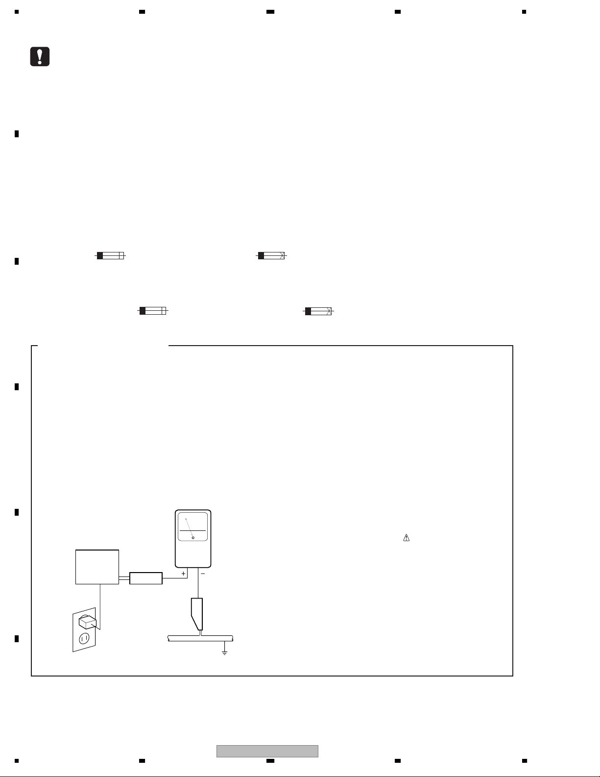
1. SAFETY PRECAUTIONS
The following check should be performed for the
continued protection of the customer and service
technician.
LEAKAGE CURRENT CHECK
Measure leakage current to a known earth ground
(water pipe, conduit, etc.) by connecting a leakage
current tester such as Simpson Model 229-2 or
equivalent between the earth ground and all exposed
D
metal parts of the appliance (input/output terminals,
screwheads, metal overlays, control shaft, etc.). Plug
the AC line cord of the appliance directly into a 120V
AC 60 Hz outlet and turn the AC power switch on. Any
current measured must not exceed 0.5 mA.
Leakage
current
Device
under
E
test
Also test with
plug reversed
(Using AC adapter
plug as required)
Test all
exposed metal
surfaces
AC Leakage Test
tester
Reading should
not be above
0.5 mA
Earth
ground
ANY MEASUREMENTS NOT WITHIN THE
LIMITS OUTLINED ABOVE ARE INDICATIVE
OF A POTENTIAL SHOCK HAZARD AND
MUST BE CORRECTED BEFORE RETURNING THE APPLIANCE TO THE CUSTOMER.
2. PRODUCT SAFETY NOTICE
Many electrical and mechanical parts in the appliance
have special safety related characteristics. These are
often not evident from visual inspection nor the
protection afforded by them necessarily can be obtained
by using replacement components rated for voltage,
wattage, etc. Replacement parts which have these
special safety characteristics are identified in this
Service Manual.
Electrical components having such features are
identified by marking with a
on the parts list in this Service Manual.
The use of a substitute replacement component which
does not have the same safety characteristics as the
PIONEER recommended replacement one, shown in the
parts list in this Service Manual, may create shock, fire,
or other hazards.
Product Safety is continuously under review and new
instructions are issued from time to time. For the latest
information, always consult the current PIONEER
Service Manual. A subscription to, or additional copies
of, PIONEER Service Manual may be obtained at a
nominal charge from PIONEER.
on the schematics and
F
2
1234
DV-575A-S
5678
This service manual is intended for qualified service technicians ; it is not meant for the casual
do-it-yourselfer. Qualified technicians have the necessary test equipment and tools, and have been
trainedto properly and safely repair complex products such as those covered by this
manual.Improperly performed repairs can adversely affect the safety and reliability of the product
and mayvoid the warranty. If you are not qualified to perform the repair of this product properly and
safely, youshould not risk trying to do so and refer the repair to a qualified service technician.
WARNING !
THE AEL (ACCESSIBLE EMISSION LEVEL) OF THE LASER POWER OUTPUT IS LESS THAN CLASS 1
BUT THE LASER COMPONENT IS CAPABLE OF EMITTING RADIATION EXCEEDING THE LIMIT FOR
CLASS 1.
A SPECIALLY INSTRUCTED PERSON SHOULD DO SERVICING OPERATION OF THE APPARATUS.
LASER DIODE CHARACTERISTICS
FOR DVD : MAXIMUM OUTPUT POWER : 5 mW
WAVELENGTH : 650 nm
FOR CD : MAXIMUM OUTPUT POWER : 5 mW
WAVELENGTH : 780 nm
A
B
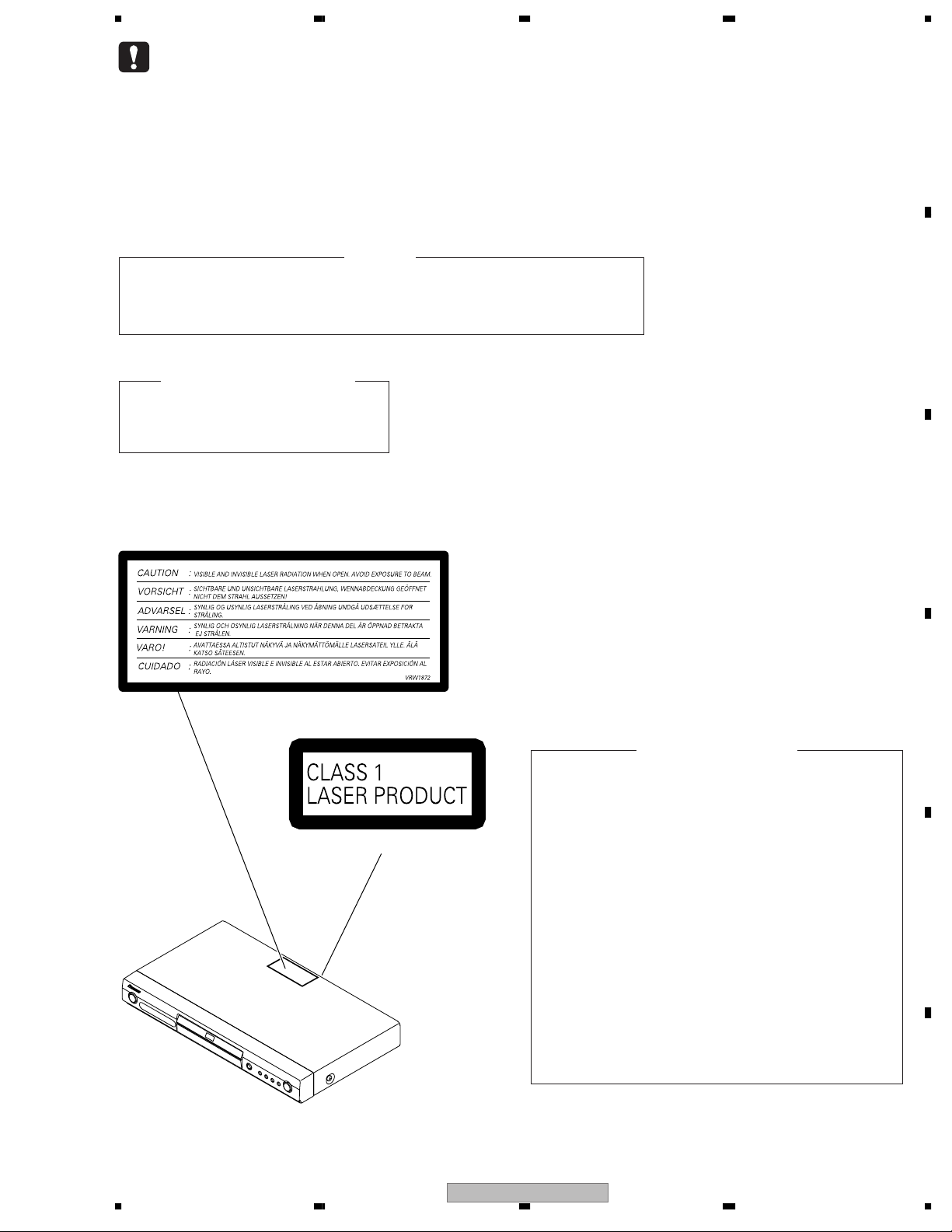
LABEL CHECK (for DV-575A-S/WYXCN, WVXCN, DV-575A-K/WYXCN)
Additional Laser Caution
1. Laser Interlock Mechanism
• Loading switch (S101 on the LOAB Assy) is used for interlock
mechanism of the laser.
When this switch turned ON in SW2 (CLOSE) side (OPEN signal is
0V and CLOSE signal is 3.5V), a laser becomes the status which can
(Printed on the Rear Panel)
completely oscillation.
Furthermore, the laser completely oscillates in the disc judgment and
disc playback.
When player is power ON state and laser diode is not completely
oscillating, 780nm laser diode is always oscillating by half power.
• Laser diode is driving with Q7 (650nm LD) and Q8 (780nm LD)
on the DVDM Assy.
Therefore, when short-circuit between the emitter and collector of these
transistors or the base voltage is supplied for transistors turn on, the
laser oscillates. (failure mode)
• In the test mode ∗ , there is the mode that the laser oscillates except
for the disc judgment and playback. LD ON mode in the test mode
oscillates with the laser forcibly.
The interlock mechanism mentioned above becomes invalid in this
mode.
C
D
E
2. When the cover is open, close viewing through the objective lens with
the naked eye will cause exposure to the laser beam.
∗ : See page 61.
DV-575A-S
56
F
3
7
8
1234
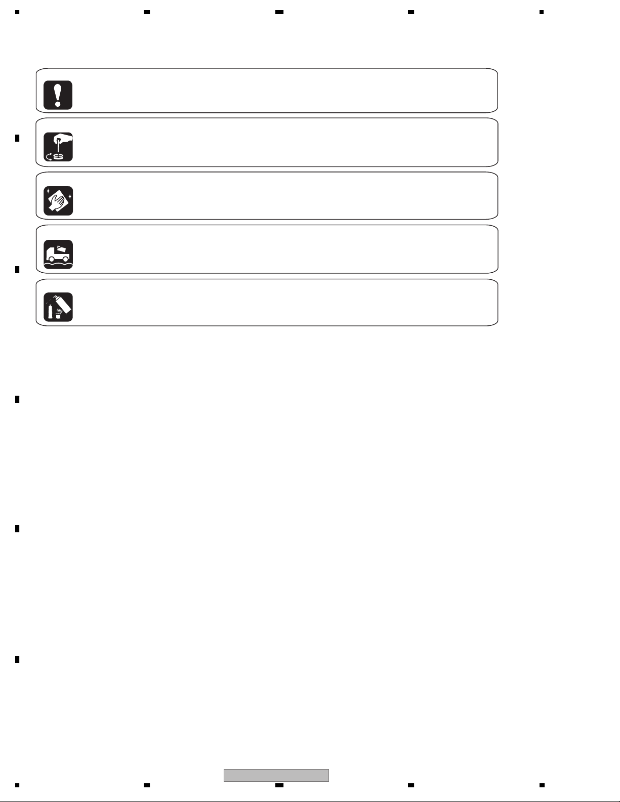
[ Important symbols for good services ]
In this manual, the symbols shown-below indicate that adjustments, settings or cleaning should be made securely.
When you find the procedures bearing any of the symbols, be sure to fulfill them:
A
1. Product safety
You should conform to the regulations governing the product (safety, radio and noise, and other regulations), and
should keep the safety during servicing by following the safety instructions described in this manual.
2. Adjustments
To keep the original performances of the product, optimum adjustments or specification confirmation is indispensable.
In accordance with the procedures or instructions described in this manual, adjustments should be performed.
3. Cleaning
B
For optical pickups, tape-deck heads, lenses and mirrors used in projection monitors, and other parts requiring cleaning,
proper cleaning should be performed to restore their performances.
4. Shipping mode and shipping screws
To protect the product from damages or failures that may be caused during transit, the shipping mode should be set or
the shipping screws should be installed before shipping out in accordance with this manual, if necessary.
5. Lubricants, glues, and replacement parts
Appropriately applying grease or glue can maintain the product performances. But improper lubrication or applying
glue may lead to failures or troubles in the product. By following the instructions in this manual, be sure to apply the
prescribed grease or glue to proper portions by the appropriate amount.For replacement parts or tools, the prescribed
ones should be used.
C
D
E
F
4
1234
DV-575A-S

5678
CONTENTS
SAFETY INFORMATION......................................................................................................................................2
1. SPECIFICATIONS.............................................................................................................................................6
2. EXPLODED VIEWS AND PARTS LIST .............................................................................................................8
2.1 PACKING ....................................................................................................................................................8
2.2 EXTERIOR SECTION (for DV-575A-S and DV-575A-K)...........................................................................10
2.3 EXTERIOR SECTION (for DV-578A-S) ....................................................................................................12
2.4 FRONT PANEL SECTION (for DV-575A-S and DV-575A-K) ....................................................................14
2.5 FRONT PANEL SECTION (for DV-578A-S)..............................................................................................16
2.6 04 LOADER ASSY ...................................................................................................................................18
3. BLOCK DIAGRAM AND SCHEMATIC DIAGRAM ..........................................................................................20
3.1 BLOCK DIAGRAM....................................................................................................................................20
3.1.1 SIGNAL ROUTE BLOCK DIAGRAM..................................................................................................20
3.1.2 POWER SUPPLY BLOCK DIAGRAM ................................................................................................22
3.2 WAVEFORMS...........................................................................................................................................24
3.3 LOAB ASSY and OVERALL WIRING DIAGRAM .....................................................................................26
3.4 DVDM ASSY (1/3) ....................................................................................................................................28
3.5 DVDM ASSY (2/3) ....................................................................................................................................30
3.6 DVDM ASSY (3/3) ....................................................................................................................................32
3.7 JCKB ASSY..............................................................................................................................................34
3.8 FLKY and PWSB ASSYS (for DV-575A-S and DV-575A-K) .....................................................................36
3.9 FLKY and PWSB ASSYS (for DV-578A-S)...............................................................................................38
3.10 POWER SUPPLY UNIT ..........................................................................................................................40
4. PCB CONNECTION DIAGRAM ......................................................................................................................41
4.1 LOAB ASSY..............................................................................................................................................41
4.2 DVDM ASSY.............................................................................................................................................42
4.3 FLKY and PWSB ASSYS (for DV-575A-S and DV-575A-K) .....................................................................46
4.4 FLKY and PWSB ASSYS (for DV-578A-S)...............................................................................................48
4.5 POWER SUPPLY UNIT (VWR1376) ........................................................................................................50
4.6 POWER SUPPLY UNIT (VWR1377) ........................................................................................................52
4.7 JCKB ASSY..............................................................................................................................................54
5. PCB PARTS LIST............................................................................................................................................55
6. ADJUSTMENT ................................................................................................................................................59
6.1 ADJUSTMENT ITEMS AND LOCATION ..................................................................................................59
6.2 JIGS AND MEASURING INSTRUMENTS ...............................................................................................59
6.3 NECESSARY ADJUSTMENT POINTS....................................................................................................60
6.4 TEST MODE .............................................................................................................................................61
6.5 MECHANISM ADJUSTMENT...................................................................................................................62
7. GENERAL INFORMATION .............................................................................................................................64
7.1 DIAGNOSIS..............................................................................................................................................64
7.1.1 TEST MODE.......................................................................................................................................64
7.1.2 DISPLAY SPECIFICATION OF THE TEST MODE ............................................................................65
7.1.3 FUNCTIONAL SPECIFICATION OF THE SHORTCUT KEY.............................................................66
7.1.4 SPECIFICATION OF MODEL INFORMATION DISPLAY...................................................................67
7.1.5 FUNCTIONAL SPECIFICATION OF THE SERVICE MODE..............................................................68
7.1.6 METHOD FOR DIAGNOSING DEGRADATION OF THE LDS ON THE PICKUP ASSY...................69
7.1.7 TROUBLE SHOOTING.......................................................................................................................70
7.1.8 ID NUMBER AND ID DATA SETTING................................................................................................73
7.1.9 SEQUENCE AFTER POWER ON .....................................................................................................76
7.1.10 DISASSEMBLY ................................................................................................................................77
7.2 IC ..............................................................................................................................................................85
7.3 DISC / CONTENT FORMAT PLAYBACK COMPATIBILITY......................................................................96
7.4 CLEANING ...............................................................................................................................................98
8. PANEL FACILITIES .........................................................................................................................................99
A
B
C
D
E
56
DV-575A-S
F
5
7
8

1234
1. SPECIFICATIONS
A
KU/CA type
Audio output (multi-channel / L, R, C, SW,
LS, RS)
General
System . . . . . . . . . . . . . . . . . . . . . . . . DVD player
Power requirements
DV-575A / DV-578A . . . . . . . . . . AC 120 V, 60 Hz
DV-676A-S
Power consumption
DV-575A / DV-578A . . . . . . . . . . . . . . . . . . . . 11 W
DV-676A-S . . . . . . . . . . . . . . . . . . . . . . . . . . . 12 W
Power consumption (standby)
DV-575A / DV-578A . . . . . . . . . . . . . . . . . . 0.07 W
B
DV-676A-S . . . . . . . . . . . . . . . . . . . . . . . . . . 0.12 W
Weight . . . . . . . . . . . . . . . . . . . 2.1 kg / 4 lb 10 oz
. . . . . . AC 110–127/220–240 V, 50/60 Hz
Dimensions . . 420 (W) x 55 (H) x 243 (D) mm
. . . . . . . . . . . . . . . (16.5 (W) x 2.2 (H) x 9.6 (D) in.)
Operating temperature . . . . . . . +5°C to +35°C
Operating humidity
. . . . . . . . . . . . . . . 5% to 85%
(+41°F to +95°F)
(no condensation)
Component video output
Y (luminance) - Output level . . . . . . 1 Vp-p (75 Ω)
PB (color) - Output level . . . . . . . 0.7 Vp-p (75 Ω)
(color) - Output level . . . . . . . 0.7 Vp-p (75 Ω)
C
P
R
Jack . . . . . . . . . . . . . . . . . . . . . . . . . . . . . . . . . RCA
S-video output
Y (luminance) - Output level . . . . . . 1 Vp-p (75 Ω)
C (color) - Output level . . . . . . 286 mVp-p (75 Ω)
Jack. . . . . . . . . . . . . . . . . . . . . . . . . . . . . . . S-video
Output level . . . . . . . . . . . . . During audio output
Number of channels . . . . . . . . . . . . . . . . . . . . . 6
Jacks . . . . . . . . . . . . . . . . . . . . . . . . . . . . RCA jack
200 mVrms (1 kHz, –20 dB)
Digital audio characteristics
Frequency response . . . . . . . . . . 4 Hz to 44 kHz
4 Hz to 88 kHz (DVD-Audio fs: 192 kHz)
S/N ratio . . . . . . . . . . . . . . . . . . . . . . . . . . . 115 dB
Dynamic range. . . . . . . . . . . . . . . . . . . . . . 101 dB
Total harmonic distortion. . . . . . . . . . . . 0.0020 %
Wow and flutter . . . . . . . . Limit of measurement
(±0.001% W. PEAK) or lower
(DVD fs: 96 kHz)
Digital output
Coaxial digital output jack. . . . . . . . . . . RCA jack
Optical digital output. . . . . . . Optical digital jack
Accessories
Audio/video cable . . . . . . . . . . . . . . . . . . . . . . . . 1
Power cable
Others . . . . . . . . . . . . . . . . . . . . . . . . . . . . . . . . 1
DV-676A-S (Singapore/Taiwan model) . . . . . . 2
Remote control . . . . . . . . . . . . . . . . . . . . . . . . . . 1
AA/R6P dry cell batteries . . . . . . . . . . . . . . . . . 2
Operating Instructions
Warranty card (
. . . . . . . . . . . . . . . . . . . . . . . . . . . . . 1
KU/CA type only).. . . . . . . . . . 1
Front panel button names sticker
(Singapore/Taiwan models only)
. . . . . . . . . . 1
Remote control overlay
Video output
Output level . . . . . . . . . . . . . . . . . . . 1 Vp-p (75 Ω)
Jack . . . . . . . . . . . . . . . . . . . . . . . . . . . . . . . . . RCA
D
Audio output (1 stereo pair)
Output level . . . . . . . . . . . . . During audio output
200 mVrms (1 kHz, –20 dB)
Number of channels . . . . . . . . . . . . . . . . . . . . . . 2
Jacks . . . . . . . . . . . . . . . . . . . . . . . . . . . . . . . RCA
(Singapore/Taiwan models only)
The specifications and design of this product are subject to
change without notice, due to improvement.
. . . . . . . . . . 1
E
F
6
1234
DV-575A-S
5678
WY and WV types
General
System . . . . . . . . . . . . . . . . . . . . . . . . . DVD player
Power requirements . . . AC 220–240 V, 50/60 Hz
Power consumption . . . . . . . . . . . . . . . . . . . 12 W
Power consumption (standby) . . . . . . . . 0.12 W
Weight . . . . . . . . . . . . . . . . . . . . . . . . . . . . . 2.1 kg
Dimensions . . 420 (W) x 55 (H) x 243 (D) mm
Operating temperature . . . . . . . . +5°C to +35°C
Operating humidity . . . . . . . . . . . . . . . 5% to 85%
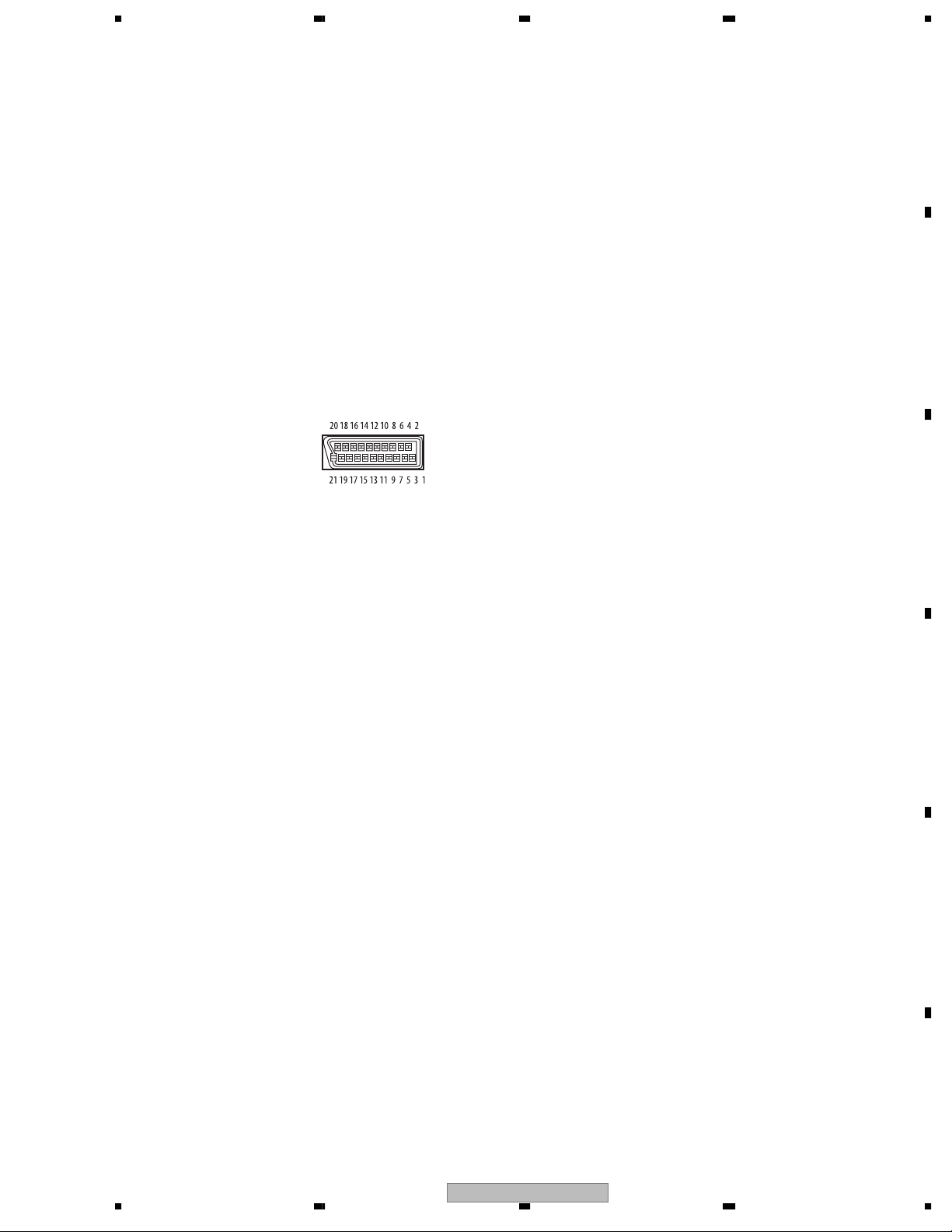
AV connector output
AV Connector (21-pin connector assignment)
AV connector output . . . . . . . . 21-pin connector
This connector provides the video and audio
signals for connection to a compatible colour TV
or monitor.
PIN no.
1 . . . . . . . . . . . . . . . . . . . . . . . . . . . . Audio 2/R out
3 . . . . . . . . . . . . . . . . . . . . . . . . . . . . Audio 1/L out
4 . . . . . . . . . . . . . . . . . . . . . . . . . . . . . . . . . . . GND
7 . . . . . . . . . . . . . . . . . . . . . . . . . . . . . . . . . . . B out
8 . . . . . . . . . . . . . . . . . . . . . . . . . . . . . . . . . . Status
11 . . . . . . . . . . . . . . . . . . . . . . . . . . . . . . . . . . G out
15 . . . . . . . . . . . . . . . . . . . . . . . . . . . . . . R or C out
17 . . . . . . . . . . . . . . . . . . . . . . . . . . . . . . . . . . GND
19 . . . . . . . . . . . . . . . . . . . . . . . Video out or Y out
21 . . . . . . . . . . . . . . . . . . . . . . . . . . . . . . . . . . GND
Component video output
Y (luminance) - Output level . . . . . . 1 Vp-p (75 Ω)
PB (color) - Output level . . . . . . . . 0.7 Vp-p (75 Ω)
(color) - Output level . . . . . . . . 0.7 Vp-p (75 Ω)
P
R
Jack . . . . . . . . . . . . . . . . . . . . . . . . . . . . . . . . RCA
(no condensation)
S-video output
Y (luminance) - Output level . . . . . . 1 Vp-p (75 Ω)
C (color) - Output level . . . . . . . 286 mVp-p (75 Ω)
Jack. . . . . . . . . . . . . . . . . . . . . . . . . . . . . . . S-video
Video output
Output level . . . . . . . . . . . . . . . . . . . 1 Vp-p (75 Ω)
Jack . . . . . . . . . . . . . . . . . . . . . . . . . . . . . . . . . RCA
Audio output (1 stereo pair)
Output level . . . . . . . . . . . . . During audio output
200 mVrms (1 kHz, –20 dB)
Number of channels . . . . . . . . . . . . . . . . . . . . . . 2
Jacks . . . . . . . . . . . . . . . . . . . . . . . . . . . . . . . RCA
Audio output (multi-channel / L, R, C, SW,
LS, RS)
Output level . . . . . . . . . . . . . During audio output
200 mVrms (1 kHz, –20 dB)
Number of channels . . . . . . . . . . . . . . . . . . . . . . 6
Jacks . . . . . . . . . . . . . . . . . . . . . . . . . . . RCA jack
Digital audio characteristics
Frequency response . . . . . . . . . . . 4 Hz to 44 kHz
(DVD fs: 96 kHz)
4 Hz to 88 kHz (DVD-Audio fs: 192 kHz)
S/N ratio . . . . . . . . . . . . . . . . . . . . . . . . . . . 115 dB
Dynamic range. . . . . . . . . . . . . . . . . . . . . . 101 dB
Total harmonic distortion . . . . . . . . . . . 0.0020 %
Wow and flutter . . . . . . . . Limit of measurement
(±0.001% W. PEAK) or lower
Digital output
Coaxial digital output jack. . . . . . . . . . . RCA jack
Optical digital output. . . . . . . Optical digital jack
Accessories
Audio/video cable . . . . . . . . . . . . . . . . . . . . . . . . 1
Power cable . . . . . . . . . . . . . . . . . . . . . . . . . . . . . 1
Remote control . . . . . . . . . . . . . . . . . . . . . . . . . . 1
AA/R6P dry cell batteries . . . . . . . . . . . . . . . . . 2
DivX compatibility sheet . . . . . . . . . . . . . . . . . . . 1
Operating Instructions . . . . . . . . . . . . . . . . . . . . 1
Warranty card . . . . . . . . . . . . . . . . . . . . . . . . . . . 1
A
B
C
D
56
DV-575A-S
E
F
7
7
8
1234
2. EXPLODED VIEWS AND PARTS LIST
NOTES:
Parts marked by "NSP" are generally unavailable because they are not in our Master Spare Parts List.
The mark found on some component parts indicates the importance of the safety factor of the part.
A
Therefore, when replacing, be sure to use parts of identical designation.
Screws adjacent to mark on product are used for disassembly.
For the applying amount of lubricants or glue, follow the instructions in this manual.
(In the case of no amount instructions, apply as you think it appropriate.)
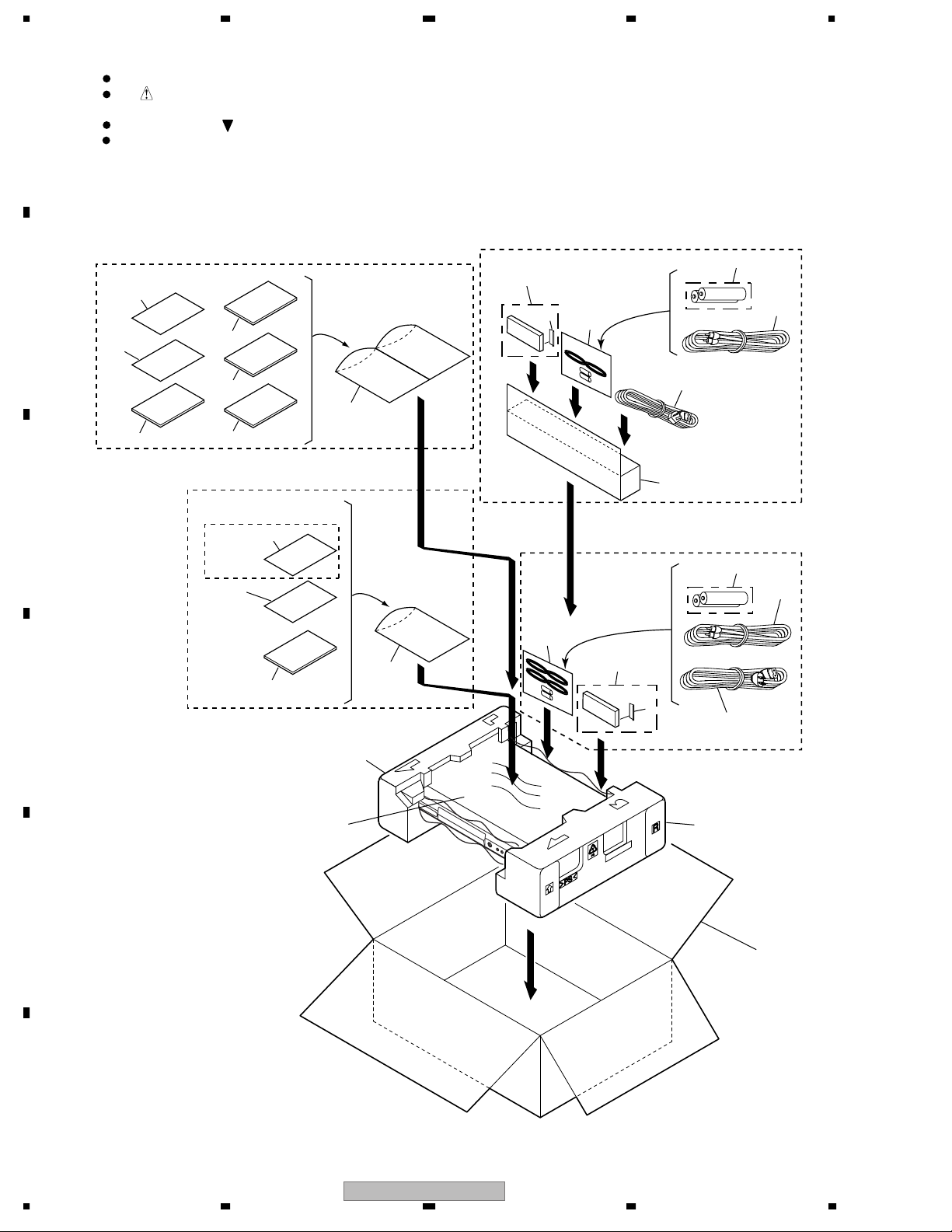
2.1 PACKING
For DV-575A-S/WYXCN and DV-575A-K/WYXCN
B
6
C
11
For DV-575A-S/WVXCN
5
3
4
12
8
9
13
7
10
For DV-575A-S/KUXCN/CA, WVXCN
and DV-578A-S/KUXCN/CA
DV-575A-S/WVXCN only
11
6
For DV-575A-S/KUXCN/CA, WYXCN
, DV-575A-K/WYXCN
and DV-578A-S/KUXCN/CA
1
18
2
5
2
12
12
7
D
15
14
E
3
4
1
16
17
F
8
1234
DV-575A-S
>
>
5678
PACKING parts List
No. Description Part No.
Mark
1Power cable See Contrast table(2)
2Audio/Video Cable VDE1078
3 Remote Control VXX2913
4 Battery Cover VNK4997
NSP 5 Dry Cell Battery (AA,R6P) VEM1010
No. Description Part No.
Mark
10 Operating Instructions See Contrast table(2)
(Spanish/Dutch)
11 DivX Compatibility Sheet See Contrast table(2)
12 Polyethylene bag B5 VHL1051
13 Polyethylene bag B5x2 See Contrast table(2)
A
NSP 6 Warranty Card See Contrast table(2)
7 Operating Instructions (English) See Contrast table(2)
8 Operating Instructions See Contrast table(2)
(English/Italian)
9 Operating Instructions See Contrast table(2)
(French/German)
14 Polyethylene Bag VHL1076
15 Pad L VHA1358
16 Pad R VHA1359
17 Packing Case See Contrast table(2)
18 Accessory Box See Contrast table(2)
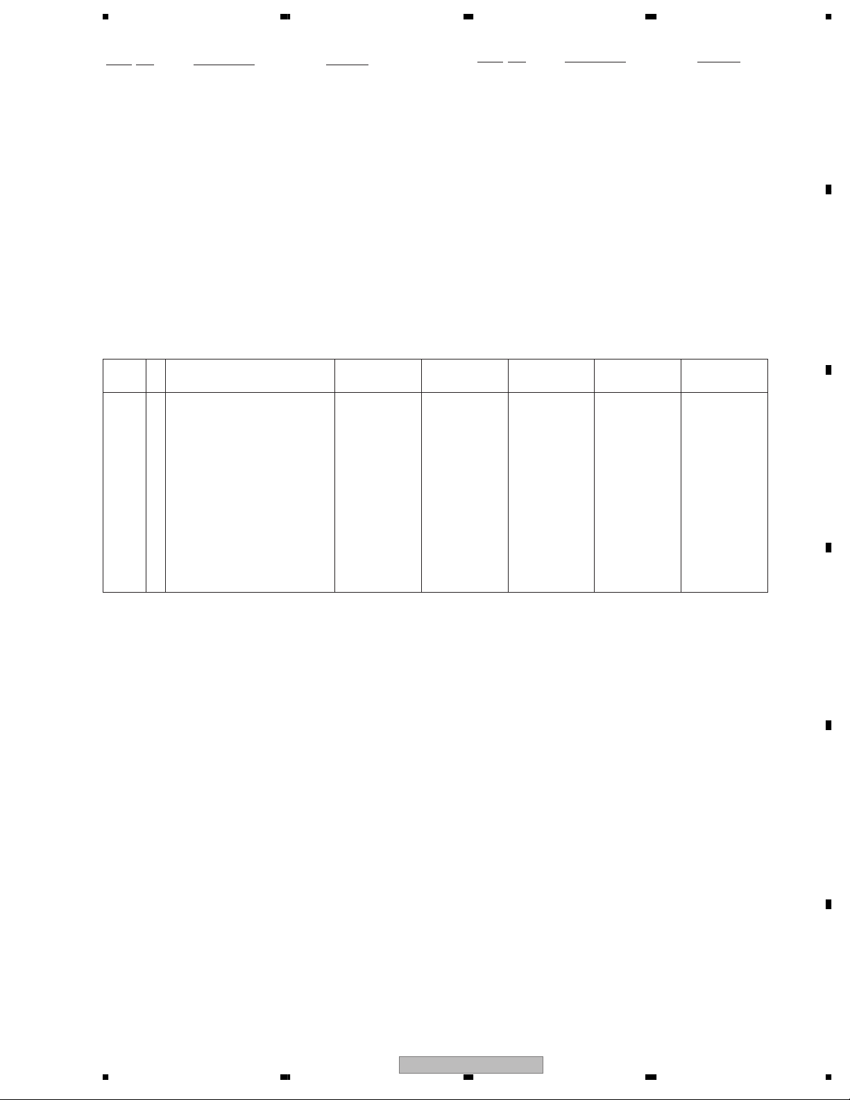
(2) CONTRAST TABLE
DV-575A-S/KUXCN/CA, WYXCN, WVXCN, DV-575A-K/WYXCN and DV-578A-S/KUXCN/CA are constructed the
same except for the following:
Mark No. Symbol and Description
1Power cable ADG7022 ADG1154 ADG1156 ADG1154 ADG7022
NSP 6 Warranty Card ARY7045 ARY7065 ARY7065 ARY7065 ARY7045
7 Operating Instructions (English) VRB1331 Not used VRB1332 Not used VRB1331
8 Operating Instructions
(English/Italian)
9 Operating Instructions
(French/German)
10 Operating Instructions
(Spanish/Dutch)
11 DivX Compatibility Sheet Not used VRX1049 VRX1049 VRX1049 Not used
13 Polyethylene bag B5x2 Not used VHL1069 Not used VHL1069 Not used
17 Packing Case VHG2489 VHG2490 VHG2497 VHG2492 VHG2496
18 Accessory Box Not used Not used VHC1114 Not used Not used
DV-575A-S/
KUXCN/CA
Not used VRD1192 Not used VRD1192 Not used
Not used VRD1193 Not used VRD1193 Not used
Not used VRD1194 Not used VRD1194 Not used
DV-575A-S/
WYXCN
DV-575A-S/
WVXCN
DV-575A-K/
WYXCN
DV-578A-S/
KUXCN/CA
B
C
D
E
F
56
DV-575A-S
9
7
8
1234
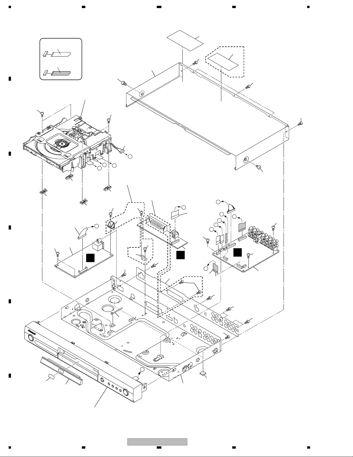
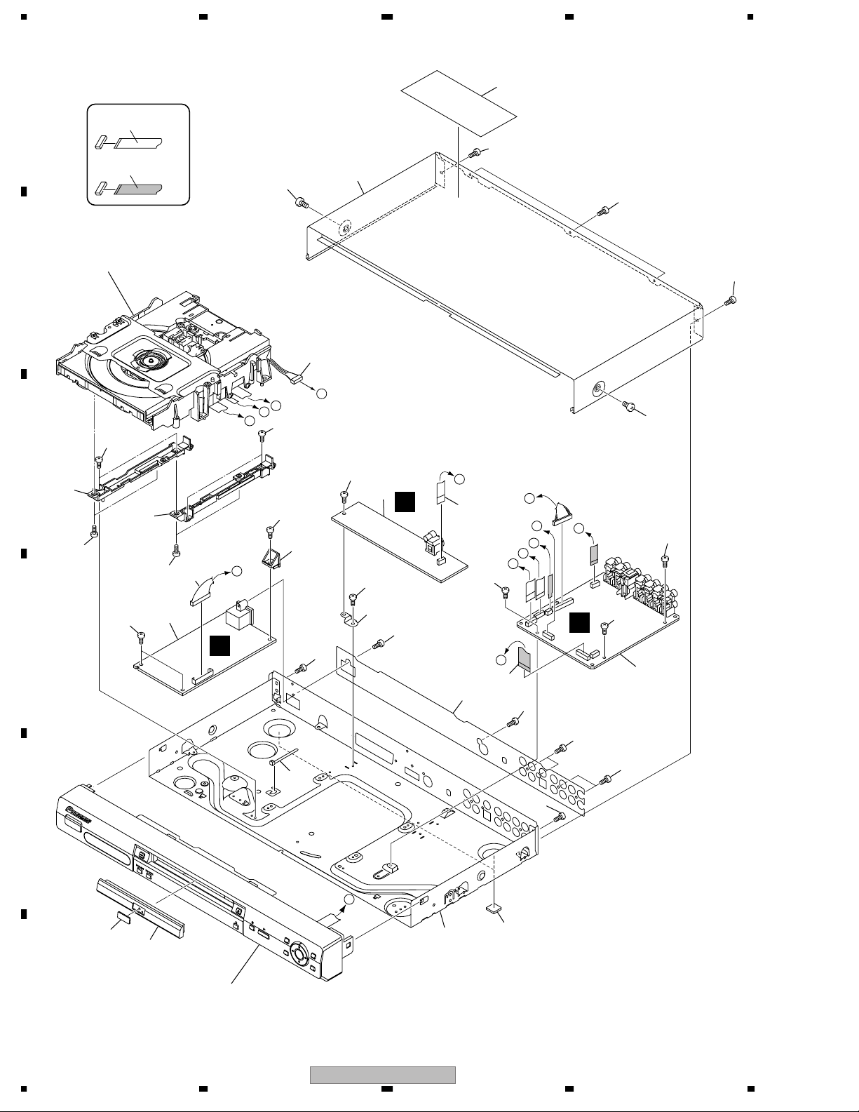
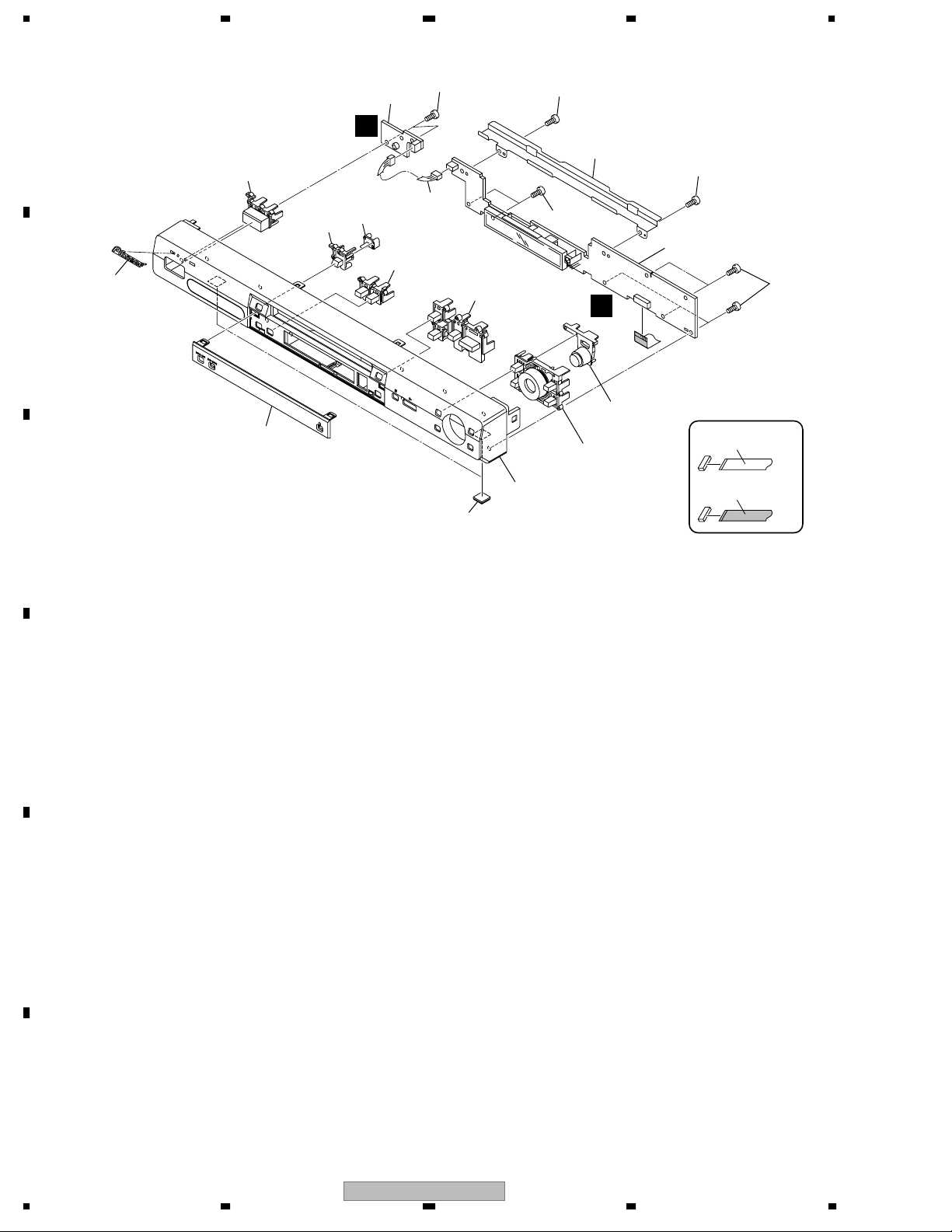
2.2 EXTERIOR SECTION (for DV-575A-S and DV-575A-K)
19
A
B
C
D
NON-CONTACT
SIDE
CONTACT SIDE
24
9
22
Refer to
"2.6 04 LOADER ASSY".
4
24
C
B
9
9
5
3
F
F
18
21
7
E
D
DV-575A-S/KUXCN/CA only
9
22
17
DV-575A-S/WYXCN, WVXCN
and DV-575A-K/WYXCN only
21
21
15
21
23
16
21
G
6
21
2
C
22
DV-575A-S/WYXCN, WVXCN
and DV-575A-K/WYXCN only
20
F
E
G
C
D
B
B
A
8
21
21
21
21
21
1
22
22
10
21
E
A
12
F
10
1234
11
Refer to "2.4 FRONT PANEL SECTION".
DV-575A-S
13
14
22
>
>
5678
EXTERIOR SECTION parts List (for DV-575A-S and DV-575A-K)
No. Description Part No.
No. Description Part No.
Mark
1DVDM Assy See Contrast table(2)
2 JCKB Assy See Contrast table(2)
3POWER SUPPLY Unit See Contrast table(2)
NSP 4 04 LOADER Assy VWT1210
5 Connector Assy (13P) VKP2320
6 Flexible Cable See Contrast table(2)
7 Connector Assy (5P) VKP2324
8 Flexible Cable (15P) VDA1991
9 Adapter 2 VNL1967
10 Binder VEC2414
11 Tray Panel See Contrast table(2)
12 DVD A/V Badge See Contrast table(2)
NSP 13 Base Chassis See Contrast table(2)
Mark
14 Rubber Foot VEB1349
15 PCB Base See Contrast table(2)
16 Rear Sheet See Contrast table(2)
17 UL Cover See Contrast table(2)
18 Bonnet See Contrast table(2)
19 KUC label VRW2063
20 Caution Label See Contrast table(2)
21 Screw BBZ30P060FNI
22 Screw BBZ30P080FNI
23 Screw PPZ30P080FNI
24 Screw BBZ30P100FNI
(2) CONTRAST TABLE
DV-575A-S/KUXCN/CA, WYXCN, WVXCN and DV-575A-K/WYXCN are constructed the same except for the following:
A
B
Mark No. Symbol and Description
1DVDM Assy VWS1582 VWS1583 VWS1583 VWS1583
2 JCKB Assy VWV1994 VWV1995 VWV1995 VWV1995
3POWER SUPPLY Unit VWR1376 VWR1377 VWR1377 VWR1377
6 Flexible Cable (5P) VDA1995 Not used Not used Not used
6 Flexible Cable (17P) Not used VDA1994 VDA1994 VDA1994
11 Tray Panel VNK5411 VNK5411 VNK5411 VNK5413
12 DVD A/V Badge VAM1131 VAM1131 VAM1131 VAM1143
NSP 13 Base Chassis VNA2703 VNA2693 VNA2693 VNA2693
15 PCB Base VNE2279 Not used Not used Not used
16 Rear Sheet VRW2060 VRW2072 VRW2072 VRW2078
17 UL Cover VNK5524 Not used Not used Not used
18 Bonnet VNA2677 VNA2677 VNA2677 VNA2678
20 Caution Label Not used VRW1872 VRW1872 VRW1872
DV-575A-S/
KUXCN/CA
DV-575A-S/
WYXCN
DV-575A-S/
WVXCN
DV-575A-K/
WYXCN
C
D
56
DV-575A-S
E
F
11
7
8
1234
2.3 EXTERIOR SECTION (for DV-578A-S)
A
NON-CONTACT
SIDE
CONTACT SIDE
21
Refer to
"2.6 04 LOADER ASSY".
4
B
19
7
20
21
21
21
11
17
21
E
21
21
2
C
21
16
23
G
18
6
21
F
E
G
C
D
B
21
21
B
A
8
22
22
1
22
D
C
B
22
22
C
9
10
23
23
5
3
22
D
F
22
F
21
E
A
13
F
12
12
Refer to "2.5 FRONT PANEL SECTION".
DV-575A-S
1234
14
15

>
5678
EXTERIOR SECTION parts List (for DV-578A-S)
No. Description Part No.
Mark
1DVDM Assy VWS1582
2 JCKB Assy VWV1994
3POWER SUPPLY Unit VWR1376
NSP 4 04 LOADER Assy VWT1210
5 Connector Assy (13P) VKP2320
6 Flexible Cable (5P) VDA1995
7 Connector Assy (5P) VKP2324
8 Flexible Cable (15P) VDA1991
9 Adapter 3L VNL1962
10 Adapter 3R VNL1963
A
11 Binder VEC2414
12 Tray Panel VNK5545
13 DVD A/V Badge VAM1131
NSP 14 Base Chassis VNA2703
15 Rubber Foot VEB1349
16 PCB Base VNE2279
17 UL Cover VNK5524
18 Rear Sheet VRW2099
19 Bonnet VNA2677
20 KUC label VRW2063
21 Screw BBZ30P060FNI
22 Screw BBZ30P080FNI
23 Screw PPZ30P080FNI
B
C
D
56
DV-575A-S
E
F
13
7
8
1234
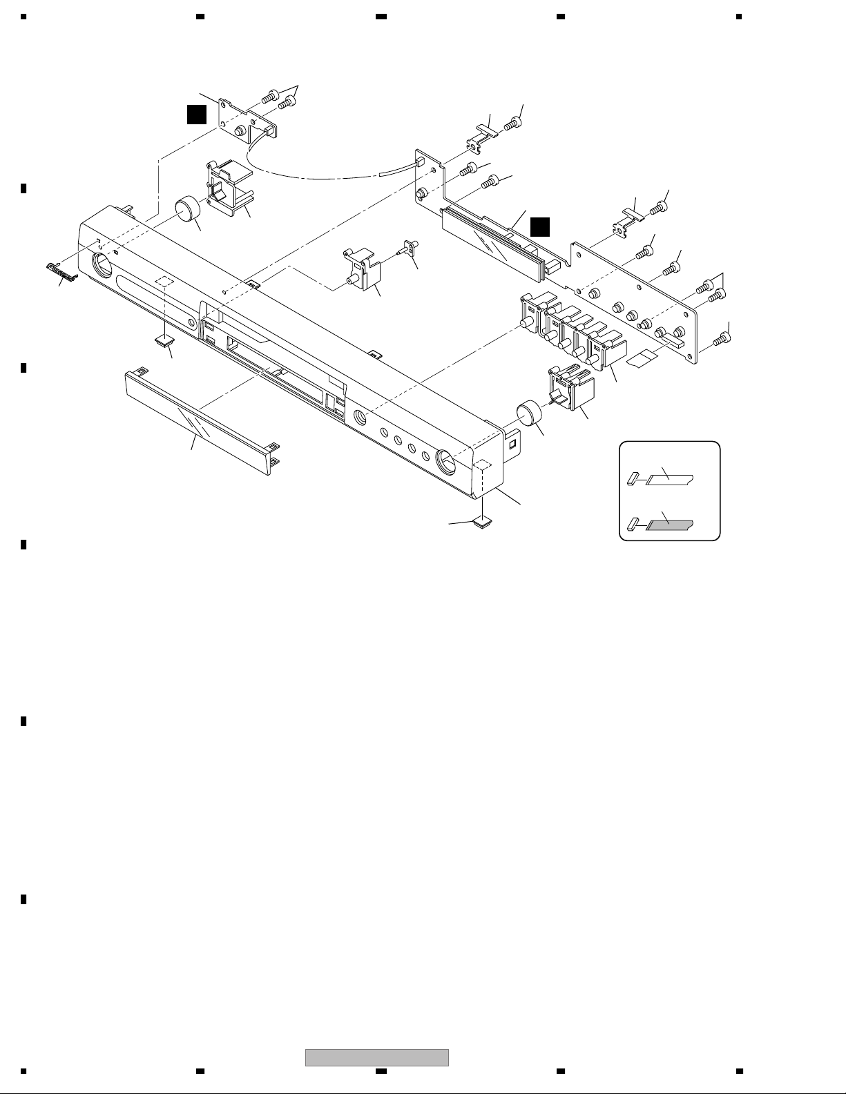
2.4 FRONT PANEL SECTION (for DV-575A-S and DV-575A-K)
A
2
E
8-1/4
7
B
6
4
C
5
11
8-2/4
11
10
11
11
1
D
9
8-4/4
8-3/4
7
11
10
11
11
NON-CONTACT
SIDE
11
11
3
4
D
E
CONTACT SIDE
F
14
1234
DV-575A-S
5678
FRONT PANEL SECTION parts List (for DV-575A-S and DV-575A-K)
No. Description Part No.
No. Description Part No.
Mark
1 FLKY Assy See Contrast table(2)
2 PWSB Assy VWG2482
3Front Panel See Contrast table(2)
4 Rubber Foot VEB1349
5 FL Lens VNK5414
6 Pioneer Name Plate See Contrast table(2)
Mark
7Key To p See Contrast table(2)
8 Main Key See Contrast table(2)
9 LED Lens VNK5415
10 FP Angle VNE2332
11 Screw PPZ30P080FNI
(2) CONTRAST TABLE
DV-575A-S/KUXCN/CA, WYXCN, WVXCN and DV-575A-K/WYXCN are constructed the same except for the following:
A
Mark No. Symbol and Description
1 FLKY Assy VWG2483 VWG2484 VWG2484 VWG2484
3Front Panel VNK5528 VNK5529 VNK5529 VNK5536
6 Pioneer Name Plate VAM1129 VAM1129 VAM1129 VAM1130
7Key To p VNK5407 VNK5410 VNK5410 VNK5409
8 Main Key VNK5404 VNK5404 VNK5404 VNK5406
DV-575A-S/
KUXCN/CA
DV-575A-S/
WYXCN
DV-575A-S/
WVXCN
DV-575A-K/
WYXCN
B
C
D
56
DV-575A-S
E
F
15
7
8
1234
2.5 FRONT PANEL SECTION (for DV-578A-S)
A
2
12
12
E
11
7-1/4
10
8
7-2/4
7-3/4
6
B
5
C
7-4/4
4
12
D
9-1/2
9-2/2
3
12
1
12
NON-CONTACT
SIDE
CONTACT SIDE
D
E
F
16
DV-575A-S
1234

5678
FRONT PANEL SECTION parts List (for DV-578A-S)
No. Description Part No.
Mark
1 FLKY Assy VWG2494
2 PWSB Assy VWG2495
3Front Panel VNK5540
4 Rubber Foot VEB1349
5 FL Lens VNK5543
6 Pioneer Name Plate VAM1129
7 Main Key VNK5541
8 LED Lens VNK5544
9 Menu Key VNK5542
10 Connector Assy (3P) VKP2305
A
NSP 11 FP Angle VNE2307
12 Screw PPZ30P080FNI
B
C
D
56
DV-575A-S
E
F
17
7
8
1234
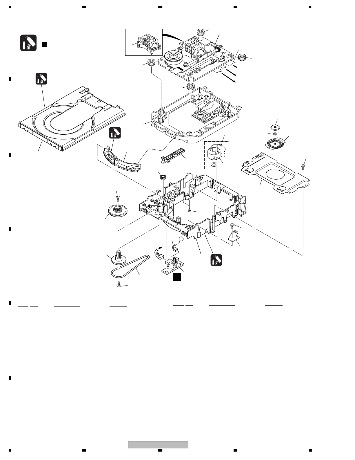
2.6 04 LOADER ASSY
A
B
C
Note :
Refer to
" Application of Lubricant".
Daifree
GEM1036
23
25
Lubricating Oil
GYA1001
13
22
12
8
2
6
8
8
8
17
16
4
To DVDM CN101 (Pickup)
To DVDM CN104 (Stepping Motor)
To DVDM CN102 (Spindle Motor)
3
A
5
19
24
18
20
22
15
14
D
04 LOADER ASSY parts List
Mark
No. Description Part No.
NSP 1 LOAB Assy VWG2346
2Traverse Mecha. Assy-S DXX2536
3 Loading Motor Assy VXX2912
4 Motor Pulley PNW1634
NSP 5 Motor VXM1107
E
6 Flexible Cable (24P) VDA1990
7 Connector Assy 2P VKP2325
8 Floating Rubber VEB1351
9 Belt VEB1358
10 Stabilizer VNE2253
22
To
DVDM CN103
9
21
22
7
A
10
11
1
A
Mark
No. Description Part No.
16 Drive Gear VNL1923
17 SW Lever VNL1925
18 Clamper Plate 04 VNE2342
19 Bridge 04 VNE2343
20 Clamper 04 VNL1969
21 Screw JGZ17P028FNI
22 Screw VBA1093
23 Tray VNL1920
24 Clamp Magnet VMG1029
25 03 SD Pickup Assy-S OXX8005
Lubricating Oil
GYA1001
11 Loading Base VNL1917
12 Float Base 04 VNL1968
13 Drive Cam VNL1919
F
14 Gear Pulley VNL1921
15 Loading Gear VNL1922
18
1234
DV-575A-S
5678
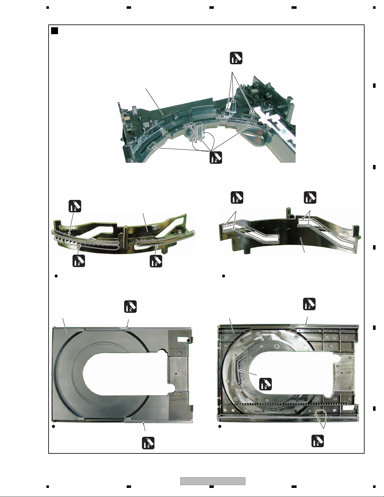
Application of Lubricant
No. 11
Loading Base
A
Lubricating Oil
GYA1001
Around the shaft
B
Lubricating Oil
GYA1001
Lubricating Oil
GYA1001
Lubricating Oil
GYA1001
No. 13
Drive Cam
Inner side of a ditch
Lubricating Oil
GYA1001
Front View Rear View
No. 23
Tray
Daifree
GEM1036
Concave of unevenness
No. 23
Tray
Lubricating Oil
GYA1001
Inner side of a ditch
Daifree
GEM1036
Lubricating Oil
GYA1001
Inner side of a ditch
No. 13
Drive Cam
Daifree
GEM1036
Concave of unevenness
C
D
E
Top View Bottom View
Concave of unevenness
Daifree
GEM1036
DV-575A-S
56
Side of the rib
Daifree
GEM1036
F
19
7
8
1234
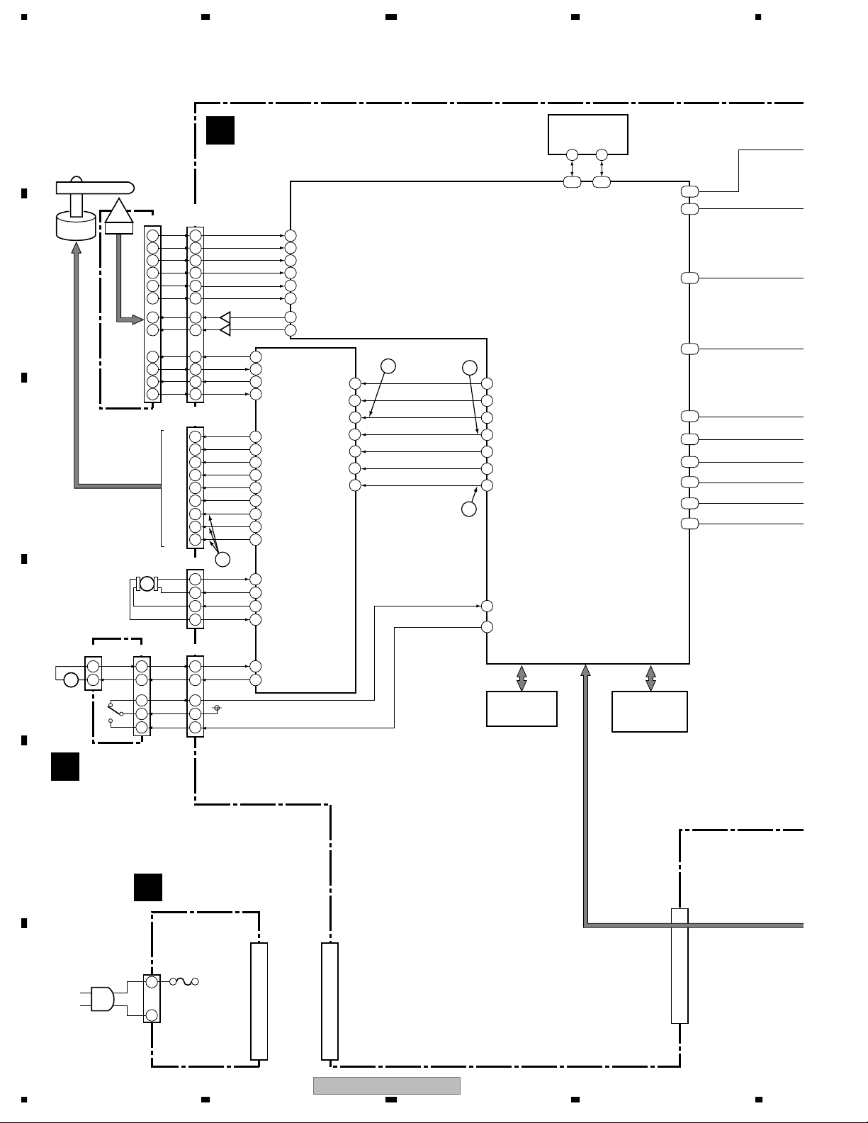
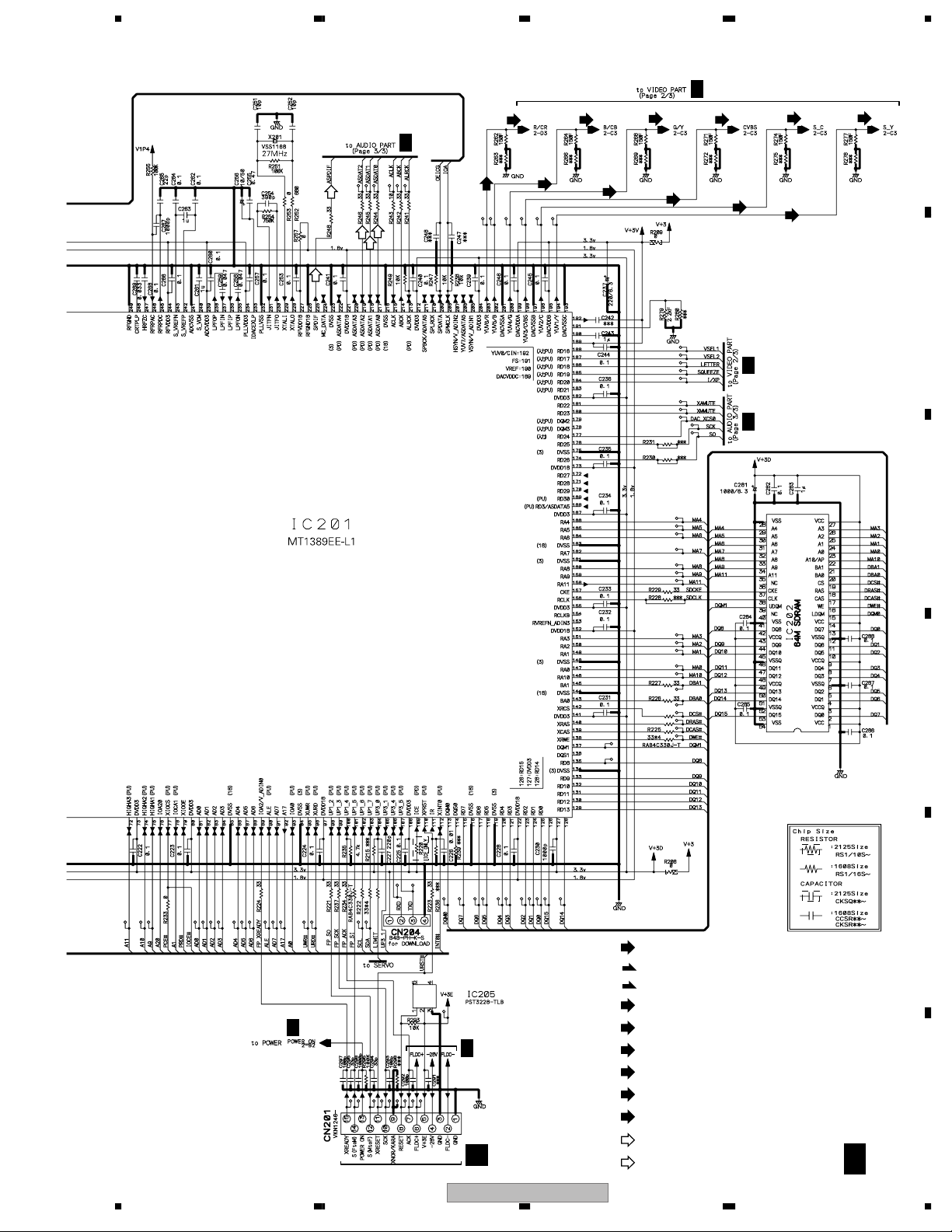
3. BLOCK DIAGRAM AND SCHEMATIC DIAGRAM
3.1 BLOCK DIAGRAM
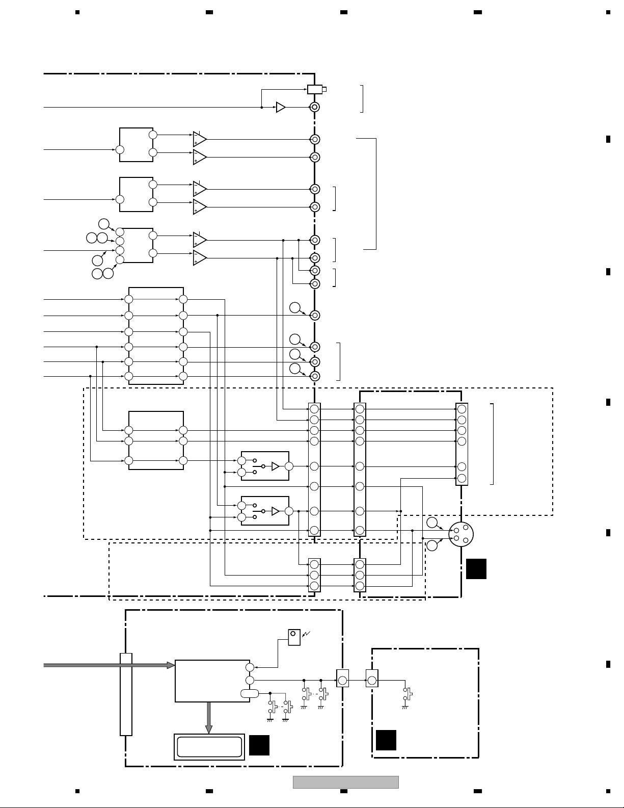
3.1.1 SIGNAL ROUTE BLOCK DIAGRAM
A
ı1/3
DVDM ASSY
B
MT1389EE-L1
FMSO
FG
DMSO
FOSO
TRSO
TROPEN
TRIN
TROUT
ı1/3
IC201
DVD IC
4
38
47
37
42
41
39
3
49
48
IC203
FLASH ROM
ı1/3
CN1013
SPINDLE
MOTOR
OEIC
B
03 SD
PICKUP
ASSY-S
C
STEPPING
MOTOR
D
CN602
M
LOADING
MOTOR
ASSY
+–
CN601
2 1
1 2
S101
CN101
(24P)
B3
22
B4
21
C
19
A
17
B1
16
B2
15
LD(780)
9
LD(650)
7 18
T DRV
4
T RTN
3
F DRV
2
F RTN
1
CN102
U+
UV+
V-
W+
WU
V
W
CN104
ST2-
M
ST2+
ST1+
ST1-
CN103
LOAD-
LOAD+
SW2
3
V+3D
4
SW1
5 5
(24P)
10
16
21
22
23
24
(12P)
10
11
Q8
Q7
HU+
HU-
HV+
HVHW+
HW-
D
A
E
F
B
C
LD2
LD1
T+
TF+
F-
U
V
W
31
30
34
35
21
FTS DRIVER
20
• Focus
19
• Tracking
18
• Stepper
• Spindle
17
• Loading Drive
• FG Detection
16
14
13
12
5
4
18
19
3
2
22
23
ı1/3
IC101
M63018FP
2
1 40
2
24
26
27
28
40
PWMOUT1
3
4
6
8
9
2
3
4
5
6
7
9
5
ST2-
1
2
3
4
1
2
3
4
ST2+
ST1+
ST1-
LOAD-
LOAD+
TRIN
V+3D
TROUT
6
5
9
10
36
37
IC204
BR24L16FV-W
EEPROM
6 5
SCL SDA
103102
IC202
K4S641632H-TC75-K
64M SDRAM
ı1/3
225
219
218
217
196
198
194
200
202
203
ASPDIF
ASDAT2
ASDAT1
ASDAT0
S_C
CVBS
S_Y
G/Y
B/Cb
R/Cr
LOAB ASSY
A
E
POWER SUPPLY
E
UNIT
CN2
(13P)
CN1
LIVE
AC IN
F
NEUTRAL
20
CN301
(13P)
DV-575A-S
CN201
(15P)
1234
5678
IC701 PCM1742KE
AUDIO DAC (C, Lfe)
ASDAT2
ASDAT1
ASDAT0
2
IC601 PCM1742KE
AUDIO DAC (Ls, Rs)
2
IC501 PCM1742KE
AUDIO DAC (L, R)
10
16
1411
1
2
3
15
13
12
S_C
CVBS
S_Y
G/Y
B/Cb
R/Cr
VOUTL
7
ı3/3
VOUTR
8
VOUTL
7
ı3/3
VOUTR
8
VOUTL
7
ı3/3
VOUTR
8
IC401
MM1623BF
VIDEO DRIVE AMP
ı2/3
C OUT
C IN
2
V OUT
V IN
4
Y OUT
Y IN
6
CY OUT
CY IN
10
Cb OUT
Cb IN
12
14
Cr IN
Cr OUT
AUDIO LPF & AMP
IC702-1/2
BA4560F
2
8
1
3
ı3/3
6
7
5
IC702-2/2
IC602-1/2
BA4560F
2
8
1
3
ı3/3
6
7
5
IC602-2/2
IC502-1/2
BA4560F
2
8
1
3
ı3/3
6
7
5
IC502-2/2
26
23
21
20
18
16
Q901
JA901
OPTICAL
COAXIAL
DIGITAL
AUDIO
OUT
Refer to "3.2 WAVEFORMS".
DVDM Assy : 2 – @
JCKB Assy : 1 – 2
A
JA502
CENTER
SUB
WOOFER
JA502
L
SURROUND
R
AUDIO
OUT
(5.1 ch)
B
JA501
L
FRONT
R
L
AUDIO
OUT (2 ch)
R
JA401
6
7
8
9
COMPOSITE
VIDEO
OUTPUT
Y
COMPONENT
VIDEO
PB
OUTPUT
PR
C
ı2/3
C OUT
C IN
2
V IN
4
Y IN
6
IC451
MM1566AJ
VIDEO DRIVE AMP
V OUT
Y OUT
15
13
10
DV-575A-S/WYXCN, WVXCN,
DV-575A-K/WYXCN ONLY
DV-575A-S/KUXCN/CA,
DV-578A-S/KUXCN/CA
ONLY
CN101
(15P)
IC101 PE5374B
MICROCOMPUTER
FL CONTROL
FRONT R
IC471 MM1505XN
H
4
6
L
IC472 MM1507XN
H
4
6
L
SEL IR
17
KEY0
22
KEY1, KEY2
20,21
CN451
(17P)
2
2
CN452
AUD.LFRONT L
13 5
AUD.R
15 3
B/Pb
11 7
G/Py
9 9
R/C/Pr
7 11
C
1 17
V/Y
5 13
Y
3 15
(5P)
V/Y
5 1
C
1 5
Y
3 3
Remote
Sensor
Unit
CN102
KEY0
CN901
(17P)
CN911
(5P)
CN103
1
2
JA902
(21P)
3
1
7
11
15
19
Y
C
JCKB ASSY
L OUT
R OUT
B
G
R/C
V/Y
CN941
S VIDEO
OUT
C
AV CONNECTOR
(RGB)-TV/AV
RECEIVER
D
E
V101
FL TUBE
FLKY ASSY
D
PWSB ASSY
E
DV-575A-S
56
F
21
7
8
1234
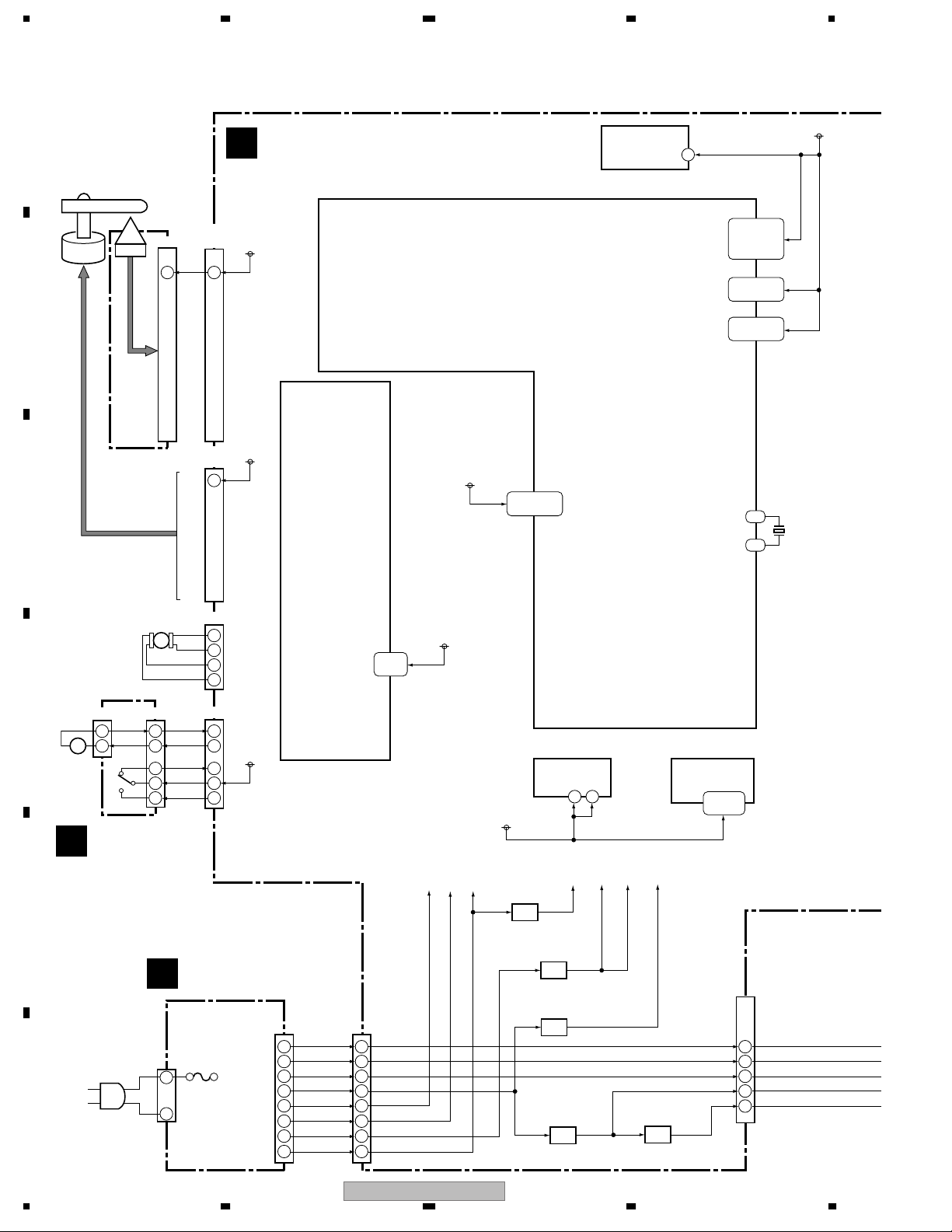
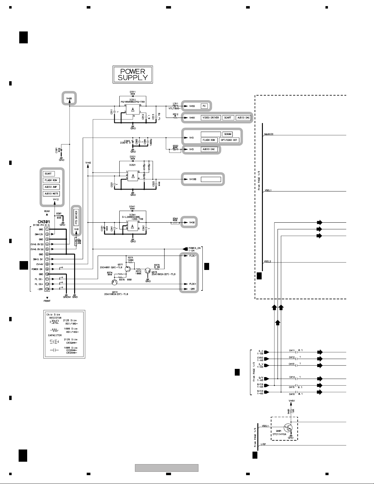
3.1.2 POWER SUPPLY BLOCK DIAGRAM
A
V+3D
V+3V
V+3RF
X201
27MHz
V+3
ı1/3
DVDM ASSY
B
ı1/3
IC201
MT1389EE-L1
SPINDLE
MOTOR
OEIC
CN1013
(24P)
VCC
CN101
(24P)
22
V+5S
DVD IC
B
03 SD
PICKUP
ASSY-S
V+5S
CN102
(12P)
1
V+5S
C
ı1/3
IC101
M63018FP
FTS DRIVER
• Focus
• Tracking
• Stepper
• Spindle
• Loading Drive
• FG Detection
V+1R8
52,97,122,
152,173,221
IC204
BR24L16FV-W
EEPROM
V+3D
8
46,65,73,80,
108,127,141,
155,167,182,
204,212
189,195,
199
24,234,239,
244,256
228
229
CN104
STEPPING
MOTOR
D
CN602
M
LOADING
MOTOR
ASSY
+–
A
CN601
2 1
1 2
S101
LOAB ASSY
ST2-
M
ST2+
ST1+
ST1-
CN103
LOAD-
LOAD+
SW2
3
V+3D
4
SW1
5 5
1
2
3
4
1
2
V+3D
3
4
3,22,
32,39
V+3
V+6
V+6
V+12
ı1/3
V+3
IC801
NJM78M05FA
5V REG.
IC203
FLASH ROM
12 37
V+3D
V+5A
V+5S V+5V
K4S641632H-TC75-K
64M SDRAM
ı1/3
V+1R8
IC202
1,3,9,14,
27,43,49
V+3D
E
IC311
PQ1M505M2ZPQ
5V REG.
POWER SUPPLY
E
UNIT
CN2
(13P)
13
FL DC+
CN1
LIVE
AC IN
F
NEUTRAL
12
FL DC-
11
EV+4V
8
SW+3.3V
7
EV+6V(A)
5
EV+6V(B)
4
SW+12V
2
-28V
CN301
13
12
11
8
7
5
4
2
(13P)
V+6B
IC321
BA00BC0WT
1.8V REG.
IC341
S-L2980A33MC-C6S
3V REG.
V+4E
V+3E
IC205
PST3228
RESET
CN201
(15P)
-28V
4
FL DC+
6
FL DC-
2
V+3E
5
RESET
8
22
DV-575A-S
1234
5678
V+3 V+5A
IC701 PCM1742KE
AUDIO DAC (C, Lfe)
ı3/3
5 6
IC601 PCM1742KE
AUDIO DAC (Ls, Rs)
ı3/3
5 6
IC501 PCM1742KE
AUDIO DAC (L, R)
ı3/3
5 6
IC401
MM1623BF
VIDEO DRIVE AMP
1,3,
5,28
ı2/3
V+5V
AUDIO LPF & AMP
IC702-1/2
BA4560F
2
8
1
3
ı3/3
6
7
5
IC702-2/2
IC602-1/2
BA4560F
2
8
1
3
ı3/3
6
7
5
IC602-2/2
IC502-1/2
BA4560F
2
8
1
3
ı3/3
6
7
5
IC502-2/2
V+12
JA901
OPTICAL
COAXIAL
JA502
CENTER
SUB
WOOFER
JA502
L
R
JA501
L
R
L
R
JA401
COMPOSITE
VIDEO
OUTPUT
Y
PB
PR
SURROUND
FRONT
AUDIO
OUT (2 ch)
COMPONENT
VIDEO
OUTPUT
DIGITAL
AUDIO
OUT
AUDIO
OUT
(5.1 ch)
A
B
C
V+5V
ı2/3
1,5,
14,16
IC451
MM1566AJ
VIDEO DRIVE AMP
DV-575A-S/WYXCN, WVXCN,
DV-575A-K/WYXCN ONLY
DV-575A-S/KUXCN/CA,
DV-578A-S/KUXCN/CA
ONLY
-28V
FL DC+
FL DC-
+3.3V
RESET
CN101
12
10
14
11
8
(15P)
V+3E
-28V
60
1 24 25 59
IC101 PE5374B
MICROCOMPUTER
1,2
FL CONTROL
6
RESET
V101
FL TUBE
IC471 MM1505XN
H
4
6
L
IC472 MM1507XN
H
4
6
L
V+3E
3
4
34,35
D
CN451
(17P)
V+5V
16 2
3
2
3
2
CN452
(5P)
CN102
X101
5MHz
FLKY ASSY
V+5
CN901
(17P)
CN911
(5P)
V+5
CN103
PWSB ASSY
E
JA902
(21P)
JCKB ASSY
L OUT
R OUT
B
G
R/C
V/Y
CN941
S VIDEO
OUT
C
AV CONNECTOR
(RGB)-TV/AV
RECEIVER
D
E
F
56
DV-575A-S
23
7
8
1234
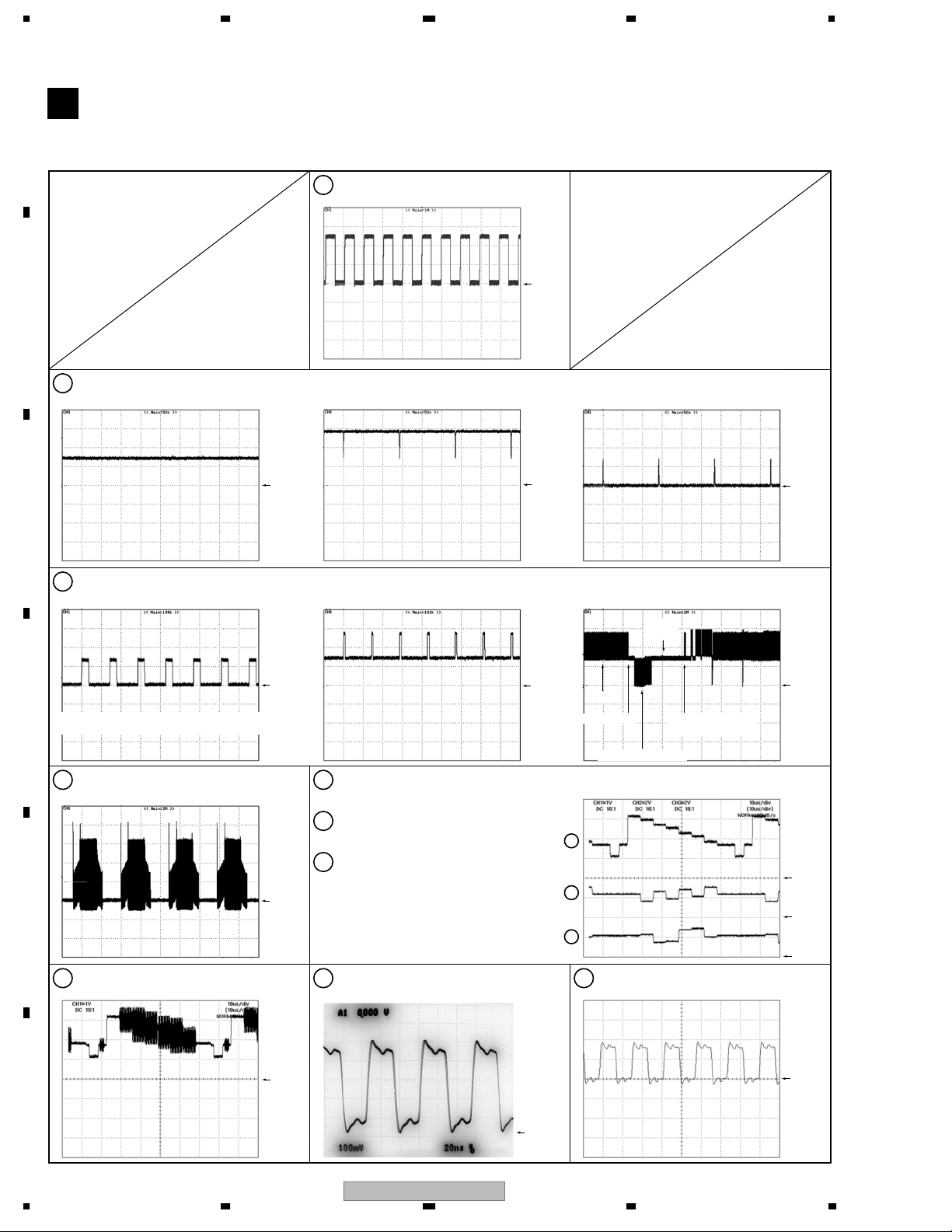
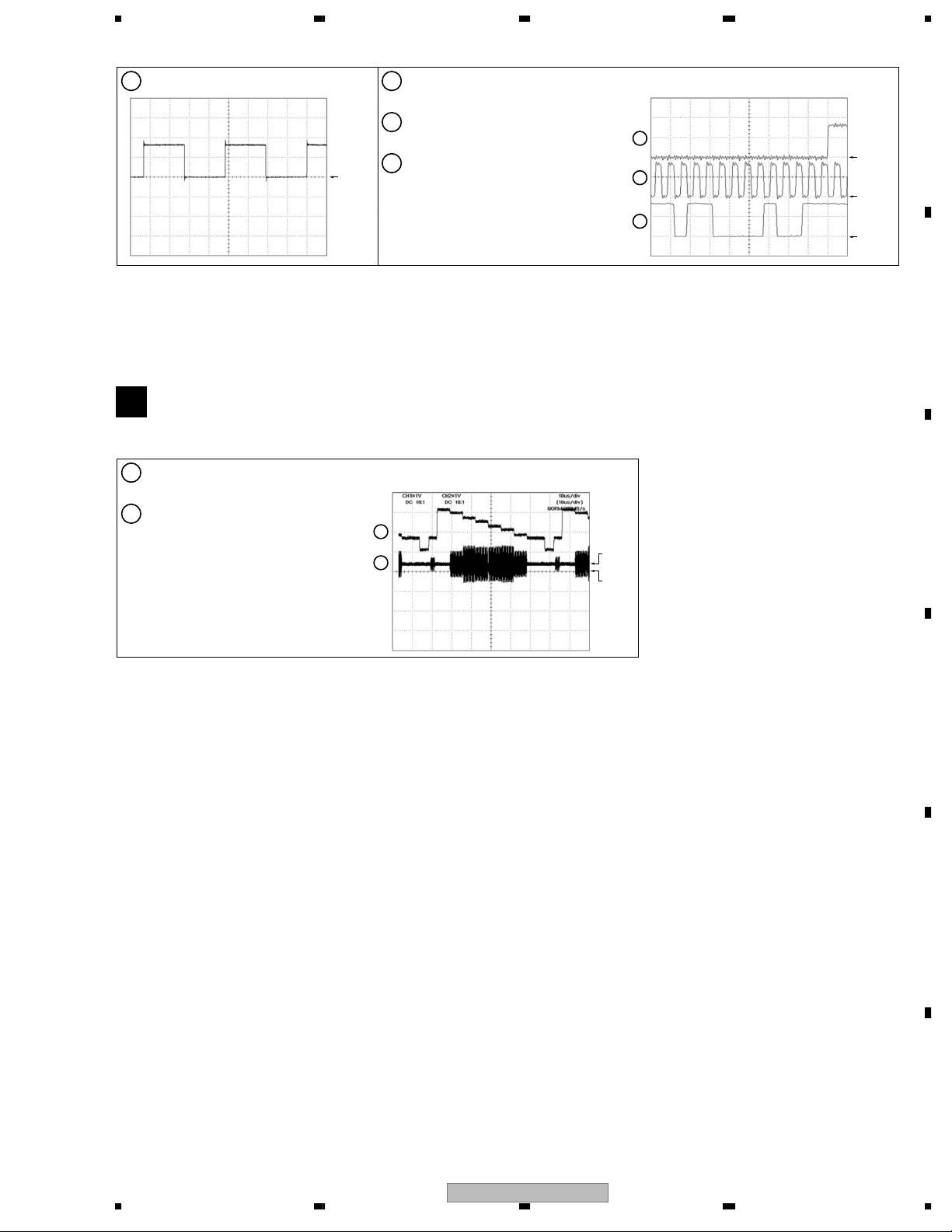
3.2 WAVEFORMS
Note : The encircled numbers denote measuring point in the schematic diagram.
DVDM ASSY
B
A
Measurement condition ;
No. 2 to 9 : reference A1 (DVD), T2-chp 19, Color-bar
No. 10 to 15 : reference A1 (DVD), T2-chp 1
IC101-pin 24 [FG]
2
V: 1V/div. H: 5msec/div.
B
IC201-pin 39 [TROPENPWM]
3
V: 1V/div. H: 5µsec/div.
[Tray stops]
[Tray is opening] [Tray is closing]
GND
C
Foot of R201 (IC201-pin 37) [DMSO]
4
V: 1V/div. H: 10µsec/div. V: 1V/div. H: 10µsec/div. V: 1V/div. H: 2sec/div.
D
OPEN KEY ON :
The condition which braking is worn in a turn of disc.
CN102-pin 11, 10, 9 (IC101-pin 14, 13, 12)
5
[SPINDLE (WVU)]
V: 2V/div. H: 2msec/div.
[DMSO_OPEN] [DMSO_PLAY] [DMS~3]
E
JA401 [Composite Video Out]
6
V: 1V/div. H: 10µsec/div.
GND
GND
GND
JA401 [Component Video Out-Y]
7
V: 1V/div. H: 10µsec/div.
JA401 [Component Video Out-PB]
8
V: 2V/div. H: 10µsec/div.
JA401 [Component Video Out-PR]
9
V: 2V/div. H: 10µsec/div.
IC501-pin 16 [PCMCK]
10
V: 100mV/div. H: 20nsec/div. fs=48kHz
GND
Tray :
opening
GND
PLAY
OPEN KEY ON PLAY KEY ON :
Braking a turn of disc
7
8
9
IC501-pin 1 [PCMBCK]
11
V: 2V/div. H: 200nsec/div.
GND
GND
starting a turn of disc
GND
GND
GND
GND
GND
F
GND
24
DV-575A-S
1234
5678
IC501-pin 3 [PCMLRCK]
12
V: 2V/div. H: 5µsec/div.
JCKB ASSY
C
Measurement condition :
reference A1 (DVD), T2-chp 19, Color-bar
CN941 [S Video Out-Y]
1
V: 1V/div. H: 10µsec/div.
CN941 [S Video Out-C]
2
V: 1V/div. H: 10µsec/div.
GND
IC501-pin 3 [PCMLRCK]
13
V: 2V/div. H: 500nsec/div.
IC501-pin 1 [PCMBCK]
14
V: 2V/div. H: 500nsec/div.
IC501-pin 2 [PCMDATA]
15
V: 2V/div. H: 500sec/div.
1
2
A
13
GND
14
GND
15
GND
B
C
GND2
GND1
D
E
F
56
DV-575A-S
25
7
8
1234
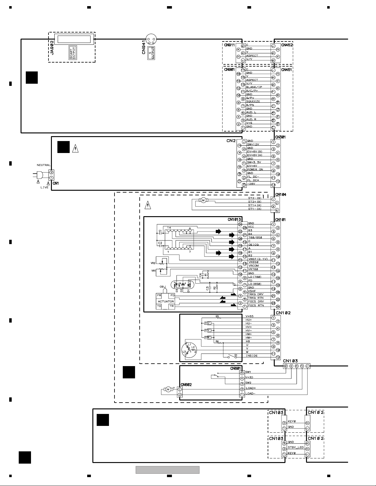
3.3 LOAB ASSY and OVERALL WIRING DIAGRAM
A
For
DV-575A-S/KUXCN/CA,
DV-575A-S/WYXCN, WVXCN,
DV-575A-K/WYXCN ONLY
DV-578A-S/KUXCN/CA
C
JCKB ASSY
(DV-575A-S/KUXCN/CA, DV-578A-S/KUXCN/CA : VWV1994)
(DV-575A-S/WYXCN, WVXCN, DV-575A-K/WYXCN : VWV1995)
For
B
DV-575A-S/WYXCN, WVXCN,
DV-575A-K/WYXCN
F
POWER SUPPLY UNIT
(DV-575A-S/KUXCN/CA, DV-578A-S/KUXCN/CA : VWR1376)
AC IN
(DV-575A-S/WYXCN, WVXCN, DV-575A-K/WYXCN : VWR1377)
C
STEPPING
MOTOR
03 SD PICKUP ASSY-S (OXX8005)
(RF)
(RF)
(RF)
(RF)
(RF)
(RF)
D
(T)
(T)
INNER
SPINDLE
MOTOR
E
04 LOADER ASSY
TRAVERSE MECHA. ASSY-S
(DXX2536)
LOAB ASSY
A
(VWG2346)
LOADING MOTOR
(VWT1210)
ASSY
(VXX2912)
S101
VSK1011
(F)
(F)
E
PWSB ASSY
F
(DV-575A-S/KUXCN/CA, WYXCN, WVXCN,
DV-575A-K/WYXCN : VWG2482)
(DV-578A-S/KUXCN/CA : VWG2495)
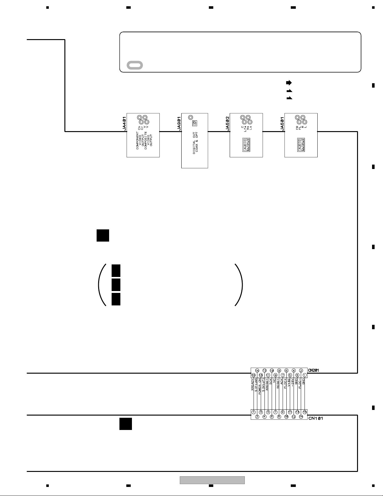
A
26
1234
DV-575A-S
For
DV-575A-S, DV-575A-K
For
DV-578A-S
5678
÷
When ordering service parts, be sure to refer to "EXPLODED VIEWS and PARTS LIST" or
"PCB PARTS LIST".
÷
The > mark found on some component parts indicates the importance of the safety factor
of the part. Therefore, when replacing, be sure to use parts of identical designation.
÷
: The power supply is shown with the marked box.
(RF)
: RF SIGNAL ROUTE
(F)
: FOCUS SERVO LOOP LINE
(T)
: TRACKING SERVO LOOP LINE
A
B
DVDM ASSY
B
(DV-575A-S/KUXCN/CA, DV-578A-S/KUXCN/CA : VWS1582)
(DV-575A-S/WYXCN, WVXCN, DV-575A-K/WYXCN : VWS1583)
B 1/3
B 2/3
B 3/3
: DVD IC BLOCK
: POWER and VIDEO BLOCK
: AUDIO BLOCK
C
D
E
D
FLKY ASSY
(DV-575A-S/KUXCN/CA : VWG2483)
(DV-575A-S/WYXCN, WVXCN, DV-575A-K/WYXCN : VWG2484)
(DV-578A-S/KUXCN/CA : VWG2494)
DV-575A-S
56
F
27
7
8
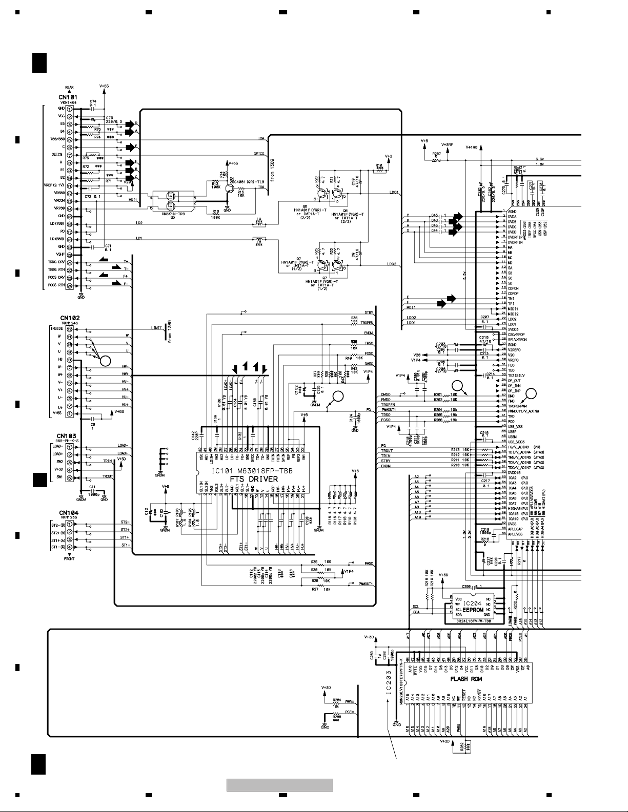
1234
3.4 DVDM ASSY (1/3)
B 1/3
A
B
03 SD PICKUP ASSY-S CN1013
C
DVDM ASSY (DV-575A-S/KUXCN/CA, DV-578A-S/KUXCN/CA : VWS1582)
(T)
(T)
(F)
(F)
5
SPINDLE MOTOR
(DV-575A-S/WYXCN, WVXCN, DV-575A-K/WYXCN : VWS1583)
(RF)
(RF)
(RF)
(RF)
(RF)
(RF)
Focus, Tracking,
Stepping, Spindle
and Loading Driver
(F)
(F)
(T)
LD Driver for CD
LD Driver for DVD
(T)
(RF)
(RF)
(RF)
(RF)
(RF)
(RF)
4
2
3
D
E
F
28
CN601
A
STEPPING MOTOR
B 1/3
1234
DV-575A-S
DV-575A-S/KUXCN/CA, DV-578A-S/KUXCN/CA : VYW2202
DV-575A-S/WYXCN, WVXCN, DV-575A-K/WYXCN : VYW2164
5678
2/3
B
(R/CR)
(B/CB)
(G/Y)
(V)
(SC)
(SY)
A
3/3B
(D)
(D)
(AD)
(B/CB)
(R/CR)
(AD)
(AD)
(G/Y)
(V)
(SC)
(SY)
B
2/3
B
3/3
B
DVD IC
(RF)
(R/CR)
B
2/3
B
2/3
CN101
D
DV-575A-S
56
(G/Y)
(B/CB)
(SY)
(SC)
(V)
(D)
(AD)
: RF SIGNAL ROUTE
(F)
: FOCUS SERVO LOOP LINE
(T)
: TRACKING SERVO LOOP LINE
: VIDEO SIGNAL ROUTE (R/CR)
: VIDEO SIGNAL ROUTE (G/Y)
: VIDEO SIGNAL ROUTE (B/CB)
: S VIDEO SIGNAL ROUTE (Y)
: S VIDEO SIGNAL ROUTE (C)
: VIDEO SIGNAL ROUTE (V)
: AUDIO SIGNAL ROUTE (DIGITAL ch)
: AUDIO DATA SIGNAL ROUTE
7
C
K4S641632H-7C75-K
D
E
F
B 1/3
29
8
1234
3.5 DVDM ASSY (2/3)
A
B
C
B 2/3
DVDM ASSY (DV-575A-S/KUXCN/CA, DV-578A-S/KUXCN/CA : VWS1582)
(DV-575A-S/WYXCN, WVXCN, DV-575A-K/WYXCN : VWS1583)
5V Regulator
DVD IC
R321
33K (F)
R323
33K (F)
BA00BC0WT
3V Regulator
1.8V Regulator
R322
33K (F)
DVD IC
(B/CB)
(G/Y)
(R/CR)
CN2
F
D
E
1/3B
1/3
B
(B/CB)
(R/CR)
(G/Y)
(SC)
(V)
(SY)
1/3
B
(G/Y)
(B/CB)
(R/CR)
F
30
B 2/3
DV-575A-S/WYXCN, WVXCN,
DV-575A-K/WYXCN ONLY
1/3
B
DV-575A-S
1234
 Loading...