

Pioneer DV-525 Service manual
DVD PLAYER
DV-525K
THIS MANUAL IS APPLICABLE TO THE FOLLOWING MODEL(S) AND TYPE(S).
ORDER NO.
RRV2207
Type
RAMXQ ‡ AC110-127/220-240V 6 Automatic select
Model
DV-525K
Power Requirement
Region No.
The voltage can be converted by
the following method.
¶ This service manual should be used together with the following manual(s):
Model No. Order No. Remarks
DV-525/KU RRV2158
CONTENTS
1. CONTRAST OF MISCELLANEOUS PARTS
2. SCHEMATIC DIAGRAM
3. PCB CONNECTION DIAGRAM
PIONEER CORPORATION 4-1, Meguro 1-chome, Meguro-ku, Tokyo 153-8654, Japan
PIONEER ELECTRONICS SERVICE, INC. P.O. Box 1760, Long Beach, CA 90801-1760, U.S.A.
PIONEER ELECTRONIC (EUROPE) N.V. Haven 1087, Keetberglaan 1, 9120 Melsele, Belgium
PIONEER ELECTRONICS ASIACENTRE PTE. LTD. 253 Alexandra Road, #04-01, Singapore 159936
PIONEER CORPORATION 1999
.......................................
..........................
........
2
7
14
T – ZZE SEPT. 1999 Printed in Japan
DV-525K
1. CONTRAST OF MISCELLANEOUS PARTS
NOTES : ÷ Parts marked by “ NSP ” are generally unavailable because they are not in our Master Spare Parts List.
÷ The
÷ Reference Nos. indicate the pages and Nos. in the service manual for the base model.
÷ When ordering resistors, first convert resistance values into code form as shown in the following examples.
7 CONTRAST TABLE
DV-525K/RAMXQ and DV-525/KU are constructed the same except for the following:
Ref.
Mark Symbol and Description
No.
mark found on some component parts indicates the importance of the safety factor of the part.
Therefore, when replacing, be sure to use parts of identical designation.
Ex. 1 When there are 2 effective digits (any digit apart from 0), such as 560 ohm and 47k ohm (tolerance is shown by
J = 5%, and K = 10%).
560 Ω = 56 × 10
47k Ω = 47 × 10
1
= 561................................................... RD1/4PU 5 6 1 J
3
= 473 .................................................. RD1/4PU 4 7 3 J
0.5 Ω = R50 ...................................................................... RN2H Â 5 0 K
1 Ω = 1R0 ......................................................................... RS1P 1 Â 0 K
Ex. 2 When there are 3 effective digits (such as in high precision metal film resistors).
1
5.62k Ω = 562 × 10
= 5621 ........................................... RN1/4PC 5 6 2 1 F
Part No.
DV-525/KU DV-525K/RAMXQ
Remarks
PCB ASSEMBLIES
P9 - 1 DVDM ASSY VWS1388 VWS1399
P9 - 2 AVJB ASSY VWV1693 VWV1695
NSP FLKB ASSY VWM1912 VWM1917
P7 - 1 FLKY ASSY VWG2050 VWG2054
P7 - 2 NSP PWSB ASSY VWG2103 VWG2058
P9 - 1 POWER SUPPLY ASSY VWR1311 VWR1313 ∗1
NSP EMIB ASSY Not used VWV1699 No. 1
PACKING
P5 - 1 Audio Cord VDE1033 VDE1054
P5 - 2 Video Cord VDE1034 VDE1055
P5 - 3 Remote Control Unit (CU-DV049) VXX2643 Not used
P5 - 3 Remote Control Unit (CU-DV046) Not used VXX2634
P5 - 4 NSP Dry Cell Battery (R6P, AA) VEM-013 VEM1010
P5 - 7 Packing Case VHG1800 VHG1832
P5 -10 NSP Warranty Card ARY7023 ARY7028
P5 -11 Operating Instructions (English) VRB1220 VRB1224
P5- 18 AC Power Cord Not used ADG7018
P5 -23 NSP Label VRW1629 Not used
Operating Instructions (Simp-Chinese) Not used VRC1092
SVCD Instruction Not used VRL1007
(English/Simp-Chinese)
Label (Packing Case) Not used VRW1814 for Packing Case
EXTERIOR SECTION
P6 - 1 Bonnet S VXX2651 VXX2652
P6 - 2 Tray Panel VNK4448 VNK4445
P6 - 6 Tray VNL1731 VNK4333
P6 -11 Screw
P6 -17 65 Label ARW7050 Not used
Nylon Rivet Not used AEC-525 No. 2
L Sheet Not used VEC2086 No. 3
BCZ40P060FZK BCZ40P060FNI
2
DV-525K
Ref.
Mark Symbol and Description
No.
FRONT PANEL SECTION
P7 - 4 Flexible Cable (09P) VDA1725 VDA1732
P7 - 5 Front Panel VNK4444 VNK4439
P7 - 6 FL Lens VEC2095 VEC2063
P7 - 7 Name Plate PAM1776 PAM1779
P7 - 8 PW Botton (POWER) VNK4101 VNK4059
P7 - 9 Main Key VNK4447 VNK4446
Flexible Cable (05P) Not used VDA1733 No. 4
(EMIB CN201 ↔ AVJB CN201)
Headphone Knob G Not used PAC1862 No. 5
Earth Plate Not used VBK1095 No. 6
BOTTOM VIEW SECTION
P9 - 8 AC Power Cord ADG7024 Not used
P9 -15 Cord Stopper CM-22C Not used
P9 -17 Rear Panel VNA2080 VNA2114
P9 -25 NSP Label VRW1629 Not used
NSP Housing Assy (2P) Not used VKP2189 for POWER SUPPLY ASSY
Label (Rear) Not used VRW1739 for Rear Panel
LOADING MECHANISM ASSY
P10 -22 Cushion VEB1312 Not used
DV-525/KU DV-525K/RAMXQ
Part No.
Remarks
∗1: This assembly is used for DV-525/WY. Refer to the service manual RRV2158.
¶ The numbers in the remarks column correspond to the numbers on the “EXPLODED VIEWS”.
¶ For PCB ASSEMBLIES, Refer to “CONTRAST OF PCB ASSEMBLIES”, “2. SCHEMATIC DIAGRAM” and “3. PCB CONNECTION DIAGRAM”.
3
DV-525K
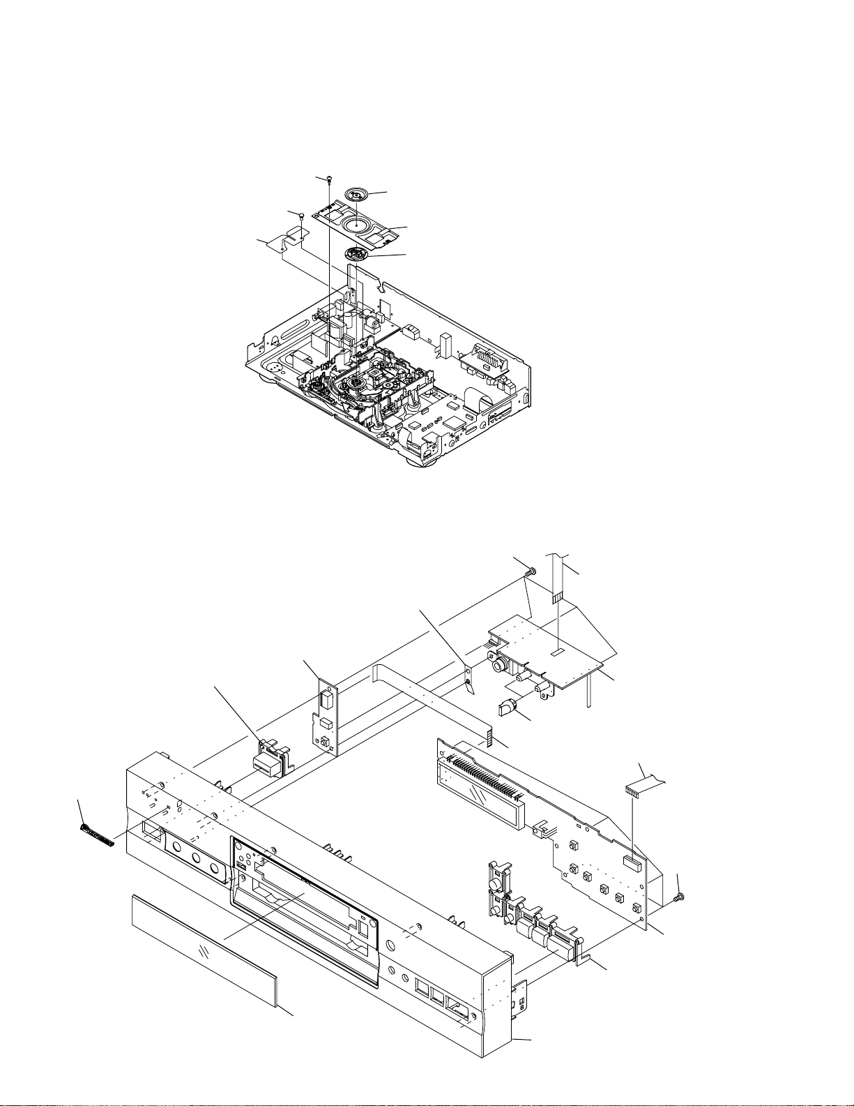
7 EXPLODED VIEWS
÷
EXTERIOR SECTION
BPZ26P080FZK
Clamper Plate
No. 2
Bridge
No. 3
Clamper
÷
FRONT PANEL SECTION
Main Key(1/2)
Name Plate
PWSB Assy
BBZ30P080FMC
No. 6
No. 4
No. 5
Flexible Cable(09P)
No. 1
Flexible Cable(14P)
BBZ30P080FMC
FLKY Assy
Main Key(2/2)
FL Lens
Front Panel
4
7 CONTRAST OF PCB ASSEMBLIES
E
DVDM ASSY
F
VWS1399 and VWS1388 are constructed the same except for the following:
DV-525K
Mark Symbol and Description
VWS1388 VWS1399
IC13 VWY1659 VYW1649
IC14 TC55V1001AF8 KM68V1000CLG-7L
R1 Not used RS1/16S333J ∗1
R602 Not used RS1/16S0R0J
Part No.
∗1: This part is used for DV-525/WY. Refer to the service manual RRV2158.
F
F
AVJB ASSY
VWV1695 and VWV1693 are constructed the same except for the following:
Mark Symbol and Description
IC206 NJM78L05A Not used
Q260, Q360 Not used 2SD2114K(VW)
Q261 Not used DTA124EK
Q361 Not used DTA124TK
L201 Not used LAU220J
L262 CHIP BEADS Not used VTL1096
S201 Not used VSH1009
S451 Not used VSH1020 ∗1
S452 VSH1009 Not used
C261, C361 Not used CEJA470M16
VWV1693 VWV1695
Part No.
Remarks
Remarks
C262 Not used CKSQYF104Z25
C290 CKSQYF104Z25 Not used
C550, C552, C555 CEAT471M6R3 Not used
R221, R455 RS1/10S0R0J Not used
R260, R360 Not used RS1/10S223J
R261, R361, R453 Not used RS1/10S103J ∗1(R453)
R270, R271 Not used RS1/10S102J
R290, R291 RS1/10S220J Not used
R292 RS1/10S6R8J Not used
R450, R456 Not used RS1/10S0R0J ∗1
R452 Not used RS1/10S153J ∗1
R550, R554 RN1/10SE1100D Not used
R551, R555 RS1/10S4R7J Not used
R552, R556 RN1/10SE3300D Not used
R553, R557 RN1/10SE4700D Not used
R558 RN1/10SC62R0D Not used
CN201 CONNECTOR Not used 52045-0545
JA505 3P PIN JACK VKB1105 Not used
JA601 1P PIN JACK (NI, BLK) VKB1077 VKB1121
PC BOARD AVJB VNP1717 VNP1730
∗1: These parts are used for DV-525/WY. Refer to the service manual RRV2158.
5
DV-525K
G
F
FLKY ASSY
VWG2054 and VWG2050 are constructed the same except for the following:
Mark Symbol and Description
Part No.
VWG2050 VWG2054
R118–R120 RS1/10S390J RS1/10S150J
R129, R130, R153 RS1/10S0R0J Not used
R131, R132 Not used RS1/10S0R0J
R141 RS1/10S622J RS1/10S163J
R143 RS1/10S363J RS1/10S272J
R190–R192 Not used RS1/10S391J ∗1
FL HOLDER VNF1087 VNF1096
Remarks
∗1: This part is used for DV-525/WY. Refer to the service manual RRV2158.
7 PCB PARTS LIST
Mark No. Description Part No. Mark No. Description Part No.
C871 CKSQYB104K25
H
F
PWSB ASSY
SWITCHES AND RELAYS
S301 ASG7013
CAPACITORS
C301 CKSQYF104Z25
RESISTORS
All Resistors RS1/10S&&&J
OTHERS
CN301 CONNECTOR 9P 52492-0920
CN302 CONNECTOR BTMK04S-1S
M
EMIB ASSY
F
SEMICONDUCTORS
IC841 M65855FP
IC811 NJM2068M
IC881 NJM2370R10
Q895 DTC124EK
D851 UDZS5.1B
C812 CKSQYB122K50
C852 CKSQYB123K50
C801, C891 CKSQYB152K50
C863 CKSQYB332K50
C862 CKSQYB333K25
C853 CKSQYB472K50
C842, C884, C885, C911 CKSQYF104Z25
C864 CKSQYF105Z16
RESISTORS
VR813, VR845 (10kΩ•B) VCS1040
Other Resistors RS1/10S&&&J
OTHERS
CN201 CONNECTOR 5P 52492-0520
CN301 CONNECTOR PLUG BTMK04P-1R
JA891 HEADPHONE JACK RKB1014
PCB BINDER VEF1040
SNAP PLATE VNE1102
JACK HOLDER VNE2199
PRINTED CIRCUIT BOARD VNP1731
COILS AND FILTERS
F9921 CHIP SOLID INDUCTOR VTF1096
CAPACITORS
C816 CCSQSL271J50
C811, C841, C859 CEAT101M10
C800, C813, C851, C881 CEAT2R2M50
C849, C883 CEAT470M16
C810, C819, C845, C855, C861 CKSQYB103K50
C865, C882 CKSQYB103K50
6
 Loading...