

Page 1
Vi./
(IJ) PIONeiER*
The Art of Entertainment
Operating Instructions
Mode d'emploi
Bedienungsanleitung
LaserHismsif
□E-UHB10n
OPTICAL DISK DRIVE UNIT
LECTEUR DE DISQUE OPTIQUE
OPTISCHES DISKETTENLAUFWERK
',V h
19 9? ^/0 0
i T -iL -b > ^ —
pp
English I
--------------------------------
Français
Deutsch
Hi
Z(DtzXßit. /N’ -f L
ifèiíтïУ)mß^iccríîJffiL^fcfc'< fcàbiz,
tzmt. ^wix<tz^i\
Nous vous remercions pour cet achat d'un produit Pioneer,
Nous vous demandons de lire soigneusement ce mode
d’emploi; vous serez ainsi à même de faire correctement
fonctionner l'appareil Après avoir bien lu le mode
d'emploi, le ranger dans un endroit sûr pour pouvoir s'y
référer ultérieurement.
^iü-r
11£
y
tt,
Thank you for buying this PIONEER product.. Please
read through these operating instructions so you wili
know how to operate your unit properly. After you have
finished reading the instructions, put them away in a safe
place for future reference.
Wir danken ihnen für den Kauf dieses Pioneer-Produkts,
Lesen Sie sich bitte diese Bedienungsanleitung durch.
Dann wissen Sie, wie Sie Ihr Gerät richtig bedienen.
Bewahren Sie sie an einem sicheren Platz auf, um auch
zukünftig nachschiagen zu können.
Page 2

Information to User
Alteration or modifications carried out without appropriate authorization may Invalidate the user's right to operate the equipment.
FOB ENGLAND
"This product complies with the Radio interference requirements of
the EC (European Community) Directive 87/3Q8/EEC "
FOB GERMANY
' Dieses Produkt entspricht den Fun/renisförvorschr/ffen der EG (87/
308/EEC). “
FOB FRANCE
'Cet article est conforme aux prescriptions de fa directive
communautaire de la CE nr 87/308/EEC~(arrêté du 16/8/89) "
FOR ITALY
"Questo apparato è conforme al DM 13 Apr. 89 (Dir. 87/308/
CEE)."
This equipment has been tested and found to comply with the limits for a Class B digital device, pursuant to Part 15 of the FCC Rules,
These limits are designed to provide reasonable protection against harmful interference in a residential instaflaiion, This equipment
generates, uses, and can radiate radio frequency energy and, if not installed and used in accordance with the instructions, may cause
harmful interference to radio communications However, there is no guarantee that interference wiil not occur in a particular installation
if this equipment does cause harmful interference to radio or television reception, which can be determined by turning the equipment
off and on, the user is encouraged to try to correct the interference by one or more of the following measures:
Reorient or relocate the receiving antenna.
Increase the separation between the equipment and receiver
Connect the equipment into an outlet on a circuit different from that to which the receiver is connected.
Consult the dealer or an experienced radio/TV technician for help.
FOR SPAIN
'Este aparato cumple las normas para Interferencias de Radio
establecidas por la Directriz de la CE (87/308/EEC).."
FOR PORTUGAL
"Este produto satisfaz ás exigencias das normas sobre
interferéncias de ràdio da Comunidade Económica Européia (87/
308/EEC).:-
FOR BELGiUM AND NETHERLANDS
"Dit produkt voldoet aan de radio-ontstoríngsvoorschriften van de
Richtiijn van de EG Raad (87/308/EEC)."
FOR DENMARK
"Dette produkt overholder det g^ldende EF~direktive no. 87/308/
EEC vede radiostoj."
[ For Canadian model ]
This digital apparatus does not exceed the Class B limits for radio noise emissions from digital apparatus set out in the Radio
Interference Regulations of the Canadian Department of Communicatioris,
CAUTION: USE OF CONTROLS OR ADJUSTMENTS OR PERFORMANCE OF PROCEDURES OTHER
THAN THOSE SPECIFIED HEREIN MAY RESULT IN HAZARDOUS RADIATION EXPOSURE.
CAUTION: THE USE OF OPTICAL INSTRUMENTS WITH THIS PRODUCT WILL INCREASE EYE HAZARDS.
[ FOR EUROPEAN AND U.K. MODELS ]
FEDERAL COMMUNICATIONS COMMISSION
CAUTION
This product contains a laser diode of a higher class than
1 To ensure continued safety, do not remove any covers
or attempt to gain access to the inside of this product.
Refer all servicing to qualified personnel.
The following caution label appears on your drive.
Location; bottom of the drive
Th/s device compiles wl/h part 15 of the FCC Rules Operation is subject
to the following two conditions: (1) This device may not cause harmful
interference, and (2) this device must accept any Interference received,
Including interference that may cause un-deslred operation
Product Name: OPTICAL DISK DRIVE UNIT
Mode! Number: DE-UH9101
Responsible Party Name: PIONEER ELECTRONICS SERVICE, INC
Address: 1925 E. DOMINQUEZ ST LONG BEACH, CA 90S10 USA
Phone: (310) 952-2359
DECURATION OF CONFORMITY
CLASSI LASER PRODUCT
LASER KLASSE 1
ORW1129I
4
<ORM1056>
En
Page 3

i For the product bearing the CE mark ]
This product complies with the EMC Directives (89/336/EEC,
92/31/EEC) and CE Marking Directive (93/68/EECI
[ Synopsis ]
The DE*UH9101 is a compact, high-performance, 5.25-inch, rewritable/WORM multifunctional optical
disk drive unit that handles large-capacity 1.7GB optical disks. SCSI controller is embedded
[ Operating Precautions ]
1
Do not let foreign objects fall into the unit nor spill water onto it
2
To assure sufficient cooling, install In a well-ventilated location While the unit is operating, proper
ventilation is required to prevent the disk temperature from rising above 50"C
Air flow into the front of the unit of 0,13mVmin or more is recommended.
3. Do not attempt internal inspection or modification of the unit
4. Protect from electro-static discharge,
5 The unit may be positioned vertically or horizontaiiy, but in either case only in the specified orienta
tion., Make sure the unit is not tilted more than 5’ in any direction.
6, Install on a level surface that is not subject to strong vibration
7 Pay attention to dew formation If condensation does form, let the unit stand for about 1 to 2 hours
before using
8
Use only specified optical disks (PIONEER DEC-17GMO rewritable optical disk, DC-17QWO WORM
optical disk, DEC-702 rewritable optlcai disk, and DC-502a WORM optica! disk).
9 Pay attention to the power supply voltage and the power supply connector polarity. Using the unit
with a power supply voltage and polarity other than that specified may result in damage to the unit or
the disk
10,Keep the unit installed in a shielded chassis like a metaiic enclosure,
11..When moving or transferring the unit and when not using the unit, be sure to remove the disk
cartridge
12 .Do not use this unit in dusty, hot, or humid places
[ Features ]
1. Can use both rewritable and WORM media of large capacity
1.7GB (using DEC-17GMO/DC-17GWO) and delivers high
speed data transfer,
2 interchangeable with former PIONEER models (using DEC-702/
DC-502a)
3 1 Mbyte data buffer is Implemented,
4, Powerful error correction capability for bit error rate of less than 10’’^
(when a PIONEER optical disk is used).
5, Long-life loading mechanism and dustproof construction for high
reliability.
6. Changer interface and Spindle control interface are
implemented
7. Low power consumption,
8 SCSI-2 command set is supported.
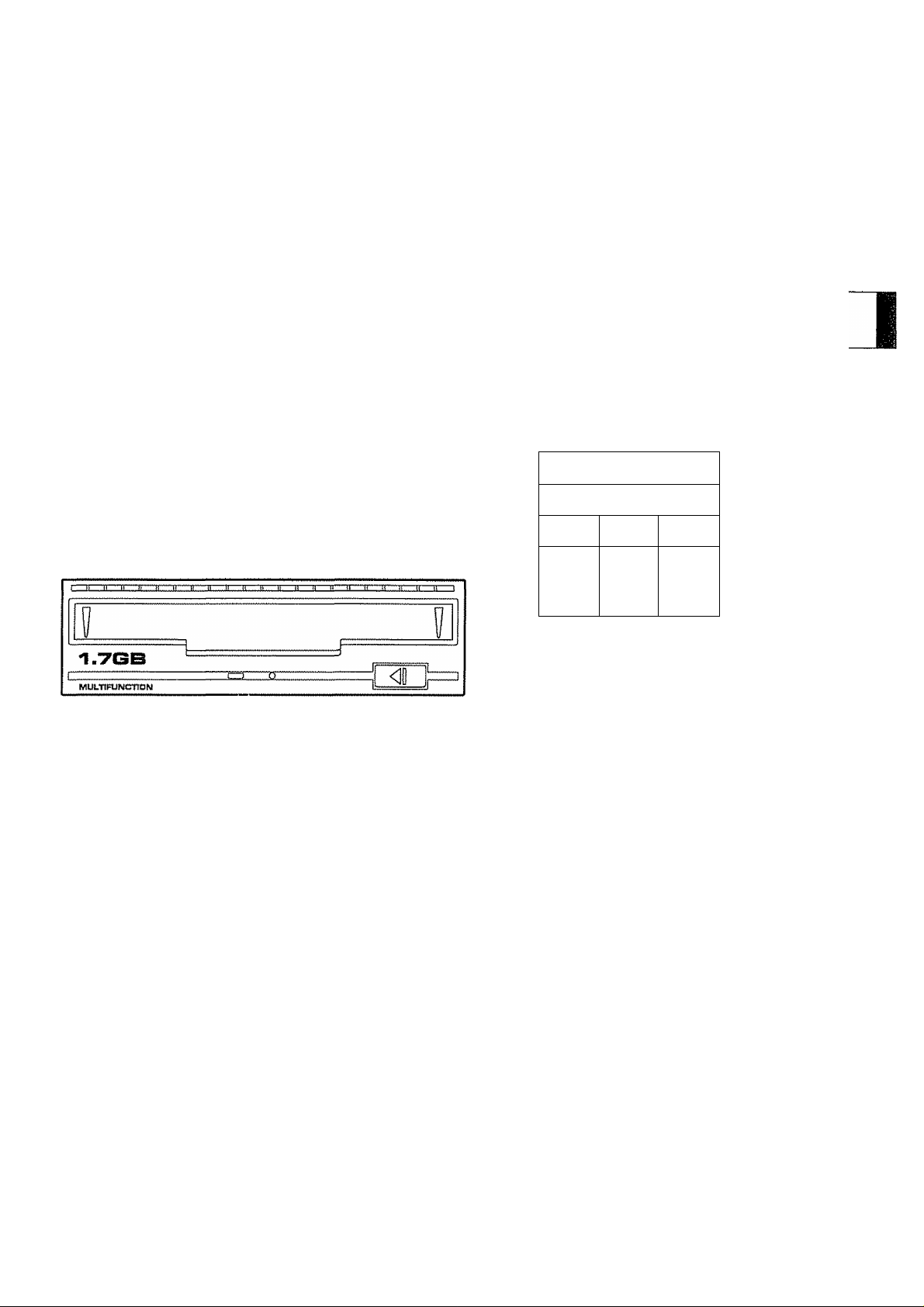
[ Facilities ]
Disk cartridge insertion slot
[ Using Manual Eject ]
When you want to remove the disk cartridge from the drive manu
ally, insert the supplied screwdriver into the manual eject screw
driver insertion hole, turn about 30 times in a counterclockwise
direction while pressing, and then remove the cartridge.
NOTE:
Be sure to switch power off before performing manual eject..
[ LED Display ]
The LED indicates the condition of the disc drive.
The LED status for each mode is as fotlows,
Drive Condition
No disk or Inappropriate
disk inserted
Green (blinking)
<lnstatlation orientation>
Horizontal installation
Vertical Instatlation
LED status mode
0
1
Yellow (blinking)
D
2
Green (blinking)
insertion hole
Power supply connector spindle control Interface
Changer interface and
DOpnODDO'l^oDOD
-I-12V ■■
GND
SCSI Jumper terminals for
-(-5V
connector SCSI ID setting etc
Rewritable disk is loaded
WORM disk Is loaded Green (blinking)Goes out
During disk access
Overhear! detection
Rewritable disk
WCRM disk
------
-----------
Goes out
Green (lights) Yeiiow (lights)
Orange
(fast blinking)
DEC-17GMO and DEC-702
DC-17GWC and DC-502a
Yeiiow (blinking)
Orange
(fast blinking)
Goes out
Goes out
Green (ilghts)
Orange
(fast blinking)
<ORM1056>
En
Page 4

[ Connecting a Daisy Chain Configuration ]
This unit uses a SCSI interface. A daisy chain configuration enables
connection of a maximum of 8 SCSI devices.
(1) Set SCSI ID using bit 1 - 3 of jumper terminals ® (see
figure below),
(2) Bit 9 of jumper terminals ® shall be OFF, only when the
unit is the last SCSI device on the daisy chain..
NOTE:
e Make sure the overall length of the SCSI cable does not exceed 6
meters (The SCSI cable 1$ sold separately.)
o Be sure not to duplicate the SCSI ID.
{Setting Jumper Terminals Ф]
@ SCSI ID (bits 1 to 3)
Sets this unit's SCSI ID (see figure below),.
(g) Parity check (bit 4)
Determines whether to perform the SCSI data bus parity check..
Performs parity check when OFF.
© Bits 5, 6 are reserved Shaii be set to OFF,
® Mode swiichirig (ШОЕ, bits 7, 8)- -
Determines the operation mode after reading the bits following
power-on or SCSI RESET
e MODE 0; Rewritable mode
о MODE 1: WORM mode
e MODE 2: SCSI-2 mode
« MODE 3: Reserved
' Mode can also be selected by an SCSI command
Ф SCSI terminator (bit 9)
Determines whether or not the unit’s SCSI terminator is to be
used
ìOH^ii^ÌcàteslthÌt:SGSÌ5timiÌnà№ié;tob(^^
NOTE;
0 All settings are in the OFF at the time of shipment from the factory
When setting to the ON, insert the supplied jumper pin.
0 Use the factory setting (OFF) for bits 4 - 6 except
o Be sure not to lose the jumper pin. When switched OFF, it is conve
nient to leave one side only connected
0 When setting with an external switch, remove all jumper pins, and
transmit the signals using a 2 54 mm pitch 2-line 18-pin connector
[ Specifications ]
e Interface
о Rotational speed
0 Bit error rate
a Dimensions
a Weight
a Power supply conditions*^
a Available positioning
a Environmental conditions
Operating temperature
Operating humidity
Storage temperature
Storage humidity
SCSI-2*’
2700rpm, ZCAV (when a DEO-17GMO
or DC-17GWO is used)
2400rpm, CAV (when a DEC-702
or DC-502A is used)
Less than 10-’^ (when a PIONEER op
tical disk is used)
Refer to the figure on P. 16 for
dimensions,
1,4kg (3ib, 1 oz)
-i-5 V, 1 „2 A typ, 2,5 A max
+12 V, 0,6 A typ, 2,5 A max
Horizontal or vertical
+5'C - +40“C (+41”F - +104“F)
10% ~ 80% RH
(no condensation)
~20^C - +50°C (-4T ~ +122T)
10% ~ 90%RH
(no condensation)
□ □ □ □ □
'i a n
3 a {
3 0 i
t
3 n [
3 □ {
bit
1 23456789
SCSI ID
Parity check
Reserved
Reserved
Mode switching
Internal SCSI terminator
VON ; not used
GN when the jumper pin is connected, OPi when removed.
SCSI ID
0
1
2
3
4
5
6
7
biti
OFF
ON
OFF
ON ON
OFF
ON
OFF
ON
bits
bit 2
OFF OFF
OFF
OFF
ON OFF
OFF
OFF ON
OFF ON
ON ON
ON ON
[ Changer interface and spindle control interface ]
This unit is equipped with a changer interface for connecting to an
auto changer controller when it is incorporated in an auto changer,
and with a spindle control interface for synchronous operation of sev
eral drives. Interface specifications are available upon request,
0 Accessories
Manual eject screwdriver
Jumper pin....................................................................................... 9
Operating instructions
*1 SCSI,.
‘2 The typical value is the value when the drive is not executing a
NOTE:
Specifications and design subject to passible modifications without
notice, due to improvements
Publtshed by Pioneer Eiectiic Corporaiion
Copyrigh! c 1994 Pioneer Sioctronic Corporation
All rights reserved
.....................
command
............................................................
................................................................
....................
Small Computer System Interface
a ij q.
3 a
V
Ф Jumper
Terminals
MODE
0 OFF
1 ON OFF
2 OFF ON
3 ON ON
bit?
bite
OFF
1
1
6
<ORM1056>
En
Page 5

4-M4 { max. 5mm )
lyPOBTANT NOTICE:
RECORD THE MODEL NUMBER AND
SERIAL NUMBER OF THIS EQUIPMENT
BELOW. THE NUMBERS ARE ON THE SIDE
PANEL.
MODEL NO. DE-UH91Q1
SERIAL NO.
_____________________________
__________________
KEEP THESE NUMBERS FOR FUTURE USE.
Published by Pioneer Eleolric Corporation
Copyright© 1994 Pioneer Electronic Corporation
. lì X 3 ^ 5L T о á t,
© 1994 A4 ^^№1
ft) ^153
AM rights reserved
PIONEER ELECTRONIC CORPORATION
industrial and Business Products Marchandising Division: 4-1, Meguro 1-Chôme, Meguro-ku, Tokyo 153, Japan
PIONEER NEW MEDIA TECHNOLOGIES, INC,
Laser Optica! Systems Division: 2265 East 220th Street, Long Beach, CA 90810, USA TEL800-444-OPTI (6784)
PiONEER ELECTRONÍC [EUROPE] N.V. Haven 1087, Keetberglaan 1, 9120 Metsele, Belgium TEL: +32-3-570-0511
PIONEER ELECTRONICS OF CANADA, INC,
Industrial Products Department: 300 Allstate Parkway, Markham, Ontario L3R 0P2, Canada TEL: 905-479-4411
PIONEER ELECTRONICS AUSTRALIA PTY„ LTD, 178-184 Boundary Road, Braeside, Victoria 3195, Australia TEL:+61-3-586-6300
PIONEER ELECTRONICS ASIACENTRE PTE. LTD, 501 Orchard Road, #10-00, Lane Crawford Place, Singapore 0923
TEL: +65-735-9011 FAX: +65-735-9022
<99J01DF0C0S>
Printed in Japan/imprimé au Japon <ORM1056-C>
 Loading...