


Service DEH-2150/X1M/ES |
|
Manual |
ORDER NO. |
|
|
|
CRT2405 |
HIGH POWER CD PLAYER WITH FM/AM TUNER
DEH-2150 X1M/ES
DEH-1150 X1M/ES
- This service manual should be used together with the following manual(s):
Model No. |
Order No. |
Mech. Module |
Remarks |
CX-958 |
CRT2423 |
S8.1 |
CD Mech. Module:Circuit Description, Mech.Description, Disassembly |
CONTENTS
1. |
SAFETY INFORMATION ............................................ |
|
2 |
7. GENERAL INFORMATION ....................................... |
46 |
2. |
EXPLODED VIEWS AND PARTS LIST ....................... |
2 |
7.1 DIAGNOSIS ........................................................ |
46 |
|
3. BLOCK DIAGRAM AND SCHEMATIC DIAGRAM ..... |
8 |
7.1.1 TEST MODE .............................................. |
46 |
||
4. |
PCB CONNECTION DIAGRAM ................................ |
|
26 |
7.1.2 DISASSEMBLY ......................................... |
49 |
5. |
ELECTRICAL PARTS LIST ........................................ |
|
36 |
7.2 PARTS ................................................................. |
53 |
6. |
ADJUSTMENT.......................................................... |
|
42 |
7.2.1 IC................................................................ |
53 |
|
|
|
|
7.2.2 DISPLAY .................................................... |
61 |
|
|
|
|
7.3 OPERATIONAL FLOW CHART ........................... |
62 |
|
|
|
|
8. OPERATIONS AND SPECIFICATIONS..................... |
63 |
|
|
|
|||
PIONEER CORPORATION |
4-1, Meguro 1-Chome, Meguro-ku, Tokyo 153-8654, Japan |
|
|||
PIONEER ELECTRONICS SERVICE INC. |
P.O.Box 1760, Long Beach, CA 90801-1760 U.S.A. |
|
|||
PIONEER ELECTRONIC [EUROPE] N.V. Haven 1087 Keetberglaan 1, 9120 Melsele, Belgium |
|
||||
PIONEER ELECTRONICS ASIACENTRE PTE.LTD. 253 Alexandra Road, #04-01, Singapore 159936 |
|
||||
C PIONEER CORPORATION 1999 |
K-ZZA. NOV. 1999 Printed in Japan |
|
DEH-2150,1150
- CD Player Service Precautions
1.For pickup unit(CXX1285) handling, please refer to"Disassembly"(see page 49).
During replacement, handling precautions shall be taken to prevent an electrostatic discharge(protection by a short pin).
2.During disassembly, be sure to turn the power off since an internal IC might be destroyed when a connector is plugged or unplugged.
3.Please checking the grating after changing the service pickup unit(see page 44).
1. SAFETY INFORMATION
This service manual is intended for qualified service technicians; it is not meant for the casual do-it-yourselfer. Qualified technicians have the necessary test equipment and tools, and have been trained to properly and safely repair complex products such as those covered by this manual.
Improperly performed repairs can adversely affect the safety and reliability of the product and may void the warranty. If you are not qualified to perform the repair of this product properly and safely; you should not risk trying to do so and refer the repair to a qualified service technician.
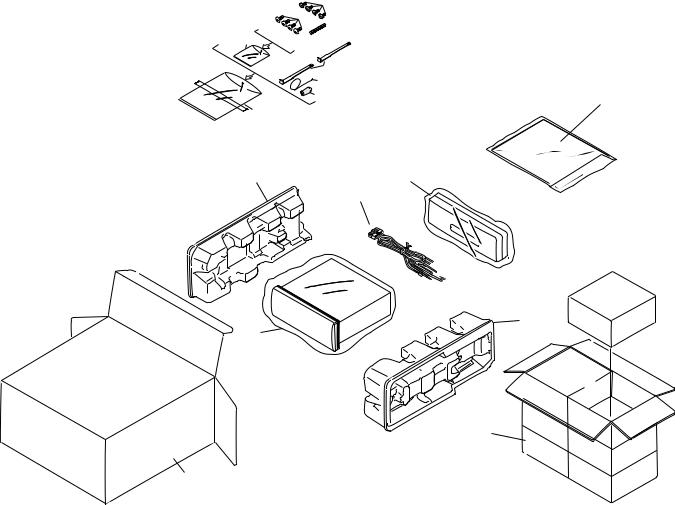
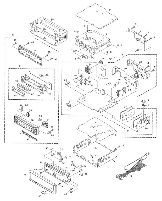
2. EXPLODED VIEWS AND PARTS LIST
2.1 PACKING
5
6

 3
3
4
8 |
|
2 |
|
9 |
11 |
14 |
16 |
|
1 |
15
10
13
12
2
DEH-2150,1150
NOTE:
-Parts marked by “*” are generally unavailable because they are not in our Master Spare Parts List.
-Screws adjacent to mark on the product are used for disassembly.
(1)PACKING SECTION PARTS LIST
Mark No. Description |
Part No. |
|
Mark No. Description |
Part No. |
|||
|
|
|
|
|
|
|
|
|
1 |
Cord Assy |
See Contrast table(2) |
11-1 |
Polyethylene Bag |
CEG1116 |
|
|
2 |
Spring |
CBH1650 |
11-2 |
Owner’s Manual |
CRD3135 |
|
|
3 |
Screw |
CBA1002 |
11-3 |
Installation Manual |
CRD3136 |
|
* |
4 |
Polyethylene Bag |
CEG-127 |
12 |
Carton |
See Contrast table(2) |
|
|
5 |
Screw |
CRZ50P090FMC |
13 |
Contain Box |
See Contrast table(2) |
|
|
6 |
Screw |
TRZ50P080FMC |
14 |
Protector |
CHP2243 |
|
* |
7 |
Polyethylene Bag |
CEG-158 |
15 |
Protector |
CHP2244 |
|
|
8 |
Handle |
CNC5395 |
16 |
Case Assy |
See Contrast table(2) |
|
|
9 |
Bush |
CNV3930 |
|
|
|
|
|
10 |
Polyethylene Bag |
CEG-162 |
|
|
|
|
(2) CONTRAST TABLE
DEH-2150/X1M/ES and DEH-1150/X1M/ES are constructed the same except for the following:
Mark No. Symbol and Description |
|
Part No. |
||
DEH-2150/X1M/ES |
|
DEH-1150/X1M/ES |
||
1 |
Cord Assy |
CDE6125 |
|
CDE6124 |
12 |
Carton |
CHG3952 |
|
CHG3955 |
13 |
Contain Box |
CHL3952 |
|
CHL3955 |
16 |
Case Assy |
CXB3520 |
|
Not used |
- Owner's Manual, Installation Manual
Model |
Part No. |
Language |
DEH-2150/X1M/ES |
CRD3135 |
English, Spanish, Portuguese(B), |
DEH-1150/X1M/ES |
CRD3136 |
Chinese, Arabic |
3
DEH-2150,1150
2.2 EXTERIOR
4

DEH-2150,1150
(1) EXTERIOR SECTION PARTS LIST
Mark No. Description |
Part No. |
Mark No. |
Description |
Part No. |
||
|
|
|
|
|
|
|
1 |
Screw |
BMZ26P120FMC |
36 |
Spring |
CBH1835 |
|
2 |
Screw |
BSZ26P060FMC |
37 |
Spring |
CBH2208 |
|
3 |
Screw |
BSZ30P060FMC |
38 |
Spring |
CBH2367 |
|
4 |
Screw |
BSZ30P120FMC |
39 |
Bracket |
CNC6791 |
|
5 |
Cord Assy |
See Contrast table(2) |
40 |
Holder |
CNC8042 |
|
6 |
Cable |
CDE6160 |
41 |
Cover |
CNM6276 |
|
7 |
Fuse(10A) |
CEK1136 |
42 |
Panel |
CNS5355 |
|
8 |
CD Mechanism Module(S8.1) |
CXK5203 |
43 |
Arm |
CNV4692 |
|
9 |
Cover |
CNC8367 |
44 |
Arm |
CNV4728 |
|
10 |
Holder |
CNC8884 |
45 |
Arm |
CNV5576 |
|
11 |
Spacer |
CNM4913 |
46 |
Screw |
IMS20P030FZK |
|
12 |
Insulator |
CNM6224 |
47 |
Detach Grille Assy |
See Contrast table(2) |
|
13 |
Insulator |
CNM6386 |
48 |
Screw |
BPZ20P100FZK |
|
14 |
Panel |
CNS5132 |
49 |
Button(Detach) |
CAC5789 |
|
15 |
Tuner Amp Assy |
See Contrast table(2) |
50 |
Button(+, -) |
CAC6273 |
|
16 |
Screw |
ASZ26P080FMC |
51 |
Chassis Unit |
See Contrast table(2) |
|
17 |
Screw |
See Contrast table(2) |
52 |
Screw |
ISS26P055FUC |
|
18 |
Screw |
BSZ26P160FMC |
53 |
IC(IC302) |
See Contrast table(2) |
|
19 |
FM/AM Tuner Unit |
CWE1501 |
54 |
Transistor(Q904, 981) |
2SD2396 |
|
20 |
Holder |
CNC7532 |
55 |
Button(Source) |
See Contrast table(2) |
|
21 |
Pin Jack(CN301) |
See Contrast table(2) |
56 |
Button(1-6) |
CAC6275 |
|
22 |
Terminal(CN403) |
CKF1059 |
57 |
Button(B, A, Cross) |
CAC6276 |
|
23 |
Connector(CN901) |
CKM1299 |
58 |
Button(Eject) |
CAC6277 |
|
24 |
Connector(CN601) |
CKS3581 |
59 |
Spring |
CBH2210 |
|
25 |
Connector(CN605) |
CKS3838 |
60 |
Cover |
CNS5772 |
|
26 |
Antenna Jack(CN402) |
CKX1056 |
61 |
Keyboard Unit |
CWM6777 |
|
27 |
Holder |
CNC7533 |
62 |
LCD(LCD1801) |
CAW1560 |
|
28 |
Holder |
See Contrast table(2) |
63 |
Connector(CN1801) |
CKS3580 |
|
29 |
Holder |
CNC8043 |
64 |
Holder |
CNC8517 |
|
30 |
Holder |
See Contrast table(2) |
65 |
Rubber |
CNV5954 |
|
31 |
Insulator |
CNM5967 |
66 |
Lighting Conductor |
CNV5965 |
|
32 |
Heat Sink |
CNR1506 |
67 |
Rubber |
CNV5966 |
|
33 |
Holder Unit |
CXB2687 |
68 |
Grille Unit |
See Contrast table(2) |
|
34 |
Case Unit |
CXB4033 |
|
|
|
|
35 |
Button |
CAC4836 |
|
|
|
|
(2) CONTRAST TABLE
DEH-2150/X1M/ES and DEH-1150/X1M/ES are constructed the same except for the following:
Mark No. Symbol and Description |
|
Part No. |
|
DEH-2150/X1M/ES |
DEH-1150/X1M/ES |
||
5 |
Cord Assy |
CDE6125 |
CDE6124 |
15 |
Tuner Amp Assy |
CWM6767 |
CWM6770 |
17 |
Screw |
BPZ26P080FMC |
Not used |
21 |
Pin Jack(CN301) |
CKB1041 |
Not used |
28 |
Holder |
CNC8041 |
Not used |
30 |
Holder |
CNC8588 |
CNC8589 |
47 |
Detach Grille Assy |
CXB4596 |
CXB4605 |
51 |
Chassis Unit |
CXB4625 |
CXB4626 |
53 |
IC(IC302) |
PAL005A |
TDA7384 |
55 |
Button(Source) |
CAC6274 |
CAC6495 |
68 |
Grille Unit |
CXB4616 |
CXB4617 |
5
DEH-2150,1150
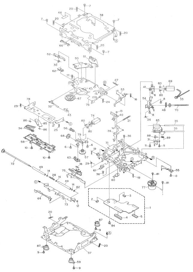
2.3 CD MECHANISM MODULE
6
DEH-2150,1150
- CD MECHANISM MODULE SECTION PARTS LIST
Mark No. Description |
Part No. |
Mark No. Description |
Part No. |
|||
1 |
Control Unit |
CWX2411 |
|
46 |
••••• |
|
2 |
Connector(CN802) |
CKS2192 |
47 |
Ball |
CNR1189 |
|
3 |
Connector(CN801) |
CKS2193 |
48 |
Belt |
CNT1086 |
|
4 |
Connector(CN701) |
CKS2773 |
49 |
Roller |
CNV4509 |
|
5 |
Connector(CN101) |
CKS3486 |
50 |
Arm |
CNV6037 |
|
6 |
Screw |
BMZ20P030FMC |
51 |
Arm |
CNV5247 |
|
7 |
Screw |
BSZ20P040FMC |
52 |
Arm |
CNV5248 |
|
8 |
Screw(M2x3) |
CBA1077 |
53 |
Arm |
CNV5249 |
|
9 |
Screw(M2x5) |
EBA1028 |
54 |
Guide |
CNV5254 |
|
10 |
Screw |
CBA1243 |
55 |
Guide |
CNV5255 |
|
11 |
Screw(M2x4) |
CBA1362 |
56 |
Gear |
CNV5257 |
|
12 |
Washer |
CBF1037 |
57 |
Gear |
CNV5256 |
|
13 |
Washer |
CBF1038 |
58 |
Guide |
CNV6176 |
|
14 |
Washer |
CBF1060 |
59 |
Damper |
CNV6174 |
|
15 |
••••• |
|
60 |
Arm |
CNV6096 |
|
16 |
Spring |
CBH2079 |
61 |
Arm |
CNV6031 |
|
17 |
Spring |
CBH2117 |
62 |
Arm |
CNV6211 |
|
18 |
Spring |
CBH2314 |
63 |
Guide |
CNV6012 |
|
19 |
Spring |
CBH2110 |
64 |
Guide |
CNV5510 |
|
20 |
Spring |
CBH2282 |
65 |
••••• |
|
|
21 |
Spring |
CBH2318 |
66 |
Guide |
CNV5751 |
|
22 |
••••• |
|
67 |
Clamper |
CNV6013 |
|
23 |
Spring |
CBH2324 |
68 |
Gear |
CNV5813 |
|
24 |
Spring |
CBH2118 |
69 |
Motor Unit(M1) |
CXB2190 |
|
25 |
Spring |
CBH2161 |
70 |
Screw Unit |
CXB4726 |
|
26 |
Spring |
CBH2163 |
71 |
Chassis Unit |
CXB4797 |
|
27 |
Spring |
CBH2189 |
72 |
Gear Unit |
CXB4728 |
|
28 |
Spring |
CBH2249 |
73 |
Arm Unit |
CXB4729 |
|
29 |
Spring |
CBH2260 |
74 |
Motor Unit(M2) |
CXB2195 |
|
30 |
Spring |
CBH2262 |
75 |
Lever Unit |
CXB4730 |
|
31 |
Bracket |
CNC8568 |
76 |
Arm Unit |
CXB4731 |
|
32 |
Spring |
CBL1369 |
77 |
Motor Unit(M3) |
CXB2562 |
|
33 |
Connector |
CDE5531 |
78 |
Arm Unit |
CXB4732 |
|
34 |
Connector |
CDE5532 |
79 |
Bracket Unit |
CXB4795 |
|
35 |
Shaft |
CLA3304 |
80 |
Screw |
JFZ20P025FMC |
|
36 |
Screw(M2.6x6) |
CBA1458 |
81 |
Screw |
JGZ17P025FZK |
|
37 |
Frame |
CNC8565 |
82 |
Washer |
YE20FUC |
|
38 |
Frame |
CNC8749 |
83 |
Pickup Unit(Service)(P8) |
CXX1285 |
|
39 |
Lever |
CNC7546 |
84 |
Screw |
IMS26P030FMC |
|
40 |
Arm |
CNC8663 |
|
* 85 PCB |
CNX2982 |
|
41 |
Bracket |
CNC8567 |
86 |
Photo-transistor(Q1, 2) |
CPT230SX-TU |
|
42 |
••••• |
|
87 |
Damper |
CNV6175 |
|
43 |
Spacer |
CNM3315 |
88 |
Rack |
CNV6014 |
|
44 |
Sheet |
CNM6659 |
89 |
Spring |
CBH2315 |
|
45 |
••••• |
|
|
|
|
|
7
A
B
C
D
1 |
|
2 |
|
3 |
|
4 |
|
|
|
|
|
DEH-2150,1150
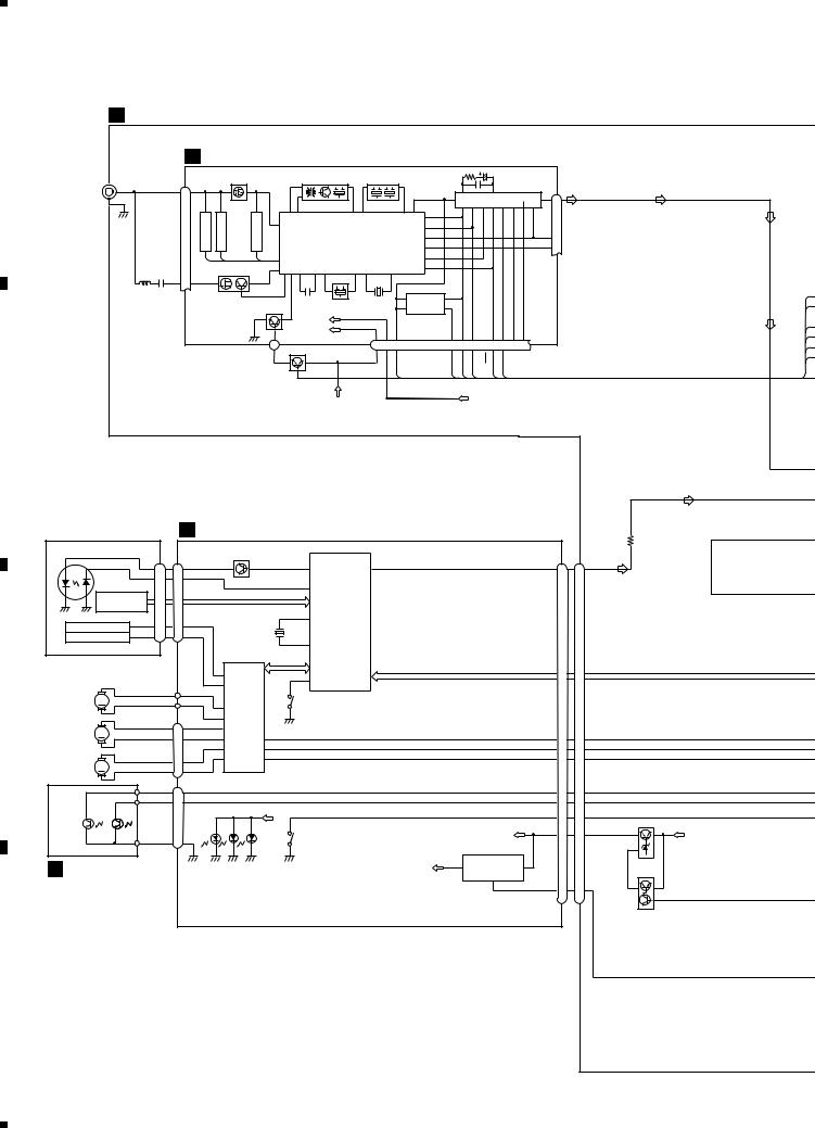
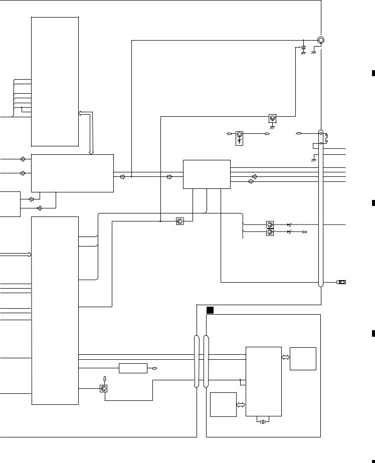
3. BLOCK DIAGRAM AND SCHEMATIC DIAGRAM
3.1 BLOCK DIAGRAM
A TUNER AMP ASSY
|
B FM/AM TUNER UNIT |
|
|
|
|
|
|
|
|
|
|
|
|
|
|
|
|
|
|
||||
|
|
FM FRONT END |
FM/AM 1ST IF 10.7MHz |
|
|
|
|
|
|
|
|
|
FM MPX |
|
|||||||||
ANTENNA |
CN402 |
Q3 |
|
|
T51 Q51 CF51 |
|
CF52 CF53 |
|
|
|
|
|
|
|
|
||||||||
|
|
|
|
|
|
|
|
|
|
|
|
|
|
|
|||||||||
|
27 |
|
|
|
|
|
|
|
|
|
|
|
|
|
25 |
|
24 |
|
|
|
|
||
|
|
|
|
|
|
|
|
|
|
|
|
32 |
|
|
|
|
|
|
|
|
19 |
|
|
|
|
|
|
|
|
|
|
|
|
|
|
|
|
|
|
IC 2 PM4008A |
6 |
||||||
|
|
|
|
|
|
|
|
|
|
|
|
|
|
|
|
|
|
||||||
|
|
|
|
38 |
39 |
|
42 |
|
44 |
|
46 |
63 |
34 |
33 |
41 |
44 |
11 |
12 |
13 |
46 |
|
||
|
|
|
|
|
|
|
|
|
|
|
|
69 |
|
||||||||||
|
TVANT1 |
TVANT2 |
TVRF |
|
|
|
|
|
|
|
|
|
|
|
|
|
|
|
|
|
|
|
|
|
22 |
|
|
|
|
|
|
|
70 |
|
|
|
|
|
|
|
|
|
|
|
|||
|
|
|
|
|
|
|
|
|
|
|
|
|
|
|
|
|
|
|
|
|
|
||
|
|
|
|
|
|
|
|
|
|
|
|
|
|
|
|
|
|
|
|
|
|
|
|
|
|
|
|
|
|
MIXER.IF AMP DET |
|
54 |
|
|
|
|
|
|
|
|
|
COMP 21 |
|||||
|
|
|
|
|
|
|
IC 1 |
|
|
|
78 |
|
|
|
|
|
|
|
|
|
LDET |
18 |
|
|
|
|
|
|
|
|
PML002A |
|
|
65 |
|
|
|
|
|
|
|
|
|
|
|
||
|
|
Q201 Q204 |
|
35 |
|
|
|
|
|
|
|
71 |
|
|
|
|
|
|
|
|
|
|
|
|
|
|
|
|
|
|
|
|
|
|
|
|
|
|
|
|
|
|
|
|
|
||
|
|
|
33 32 45 |
55 |
57 |
CF202 |
61 |
74 |
|
75 |
|
|
|
|
|
|
|
|
|
|
|
|
|
|
28 |
|
|
|
|
|
|
|
|
|
|
|
|
|
|
|
|||||||
|
|
|
|
|
|
|
|
|
|
|
EEPROM |
|
|
|
|
|
|
|
|
|
|
|
|
|
|
AM RF |
|
|
|
|
|
|
|
|
5 |
4 |
|
|
|
|
|
|
|
|
|
|
|
|
|
|
|
|
|
|
|
|
|
IC 3 |
|
|
|
|
|
|
|
|
|
|
|||
|
|
|
|
|
AM 2ND IF 450kHz |
|
6 |
3 |
|
|
|
|
|
|
|
|
|
|
|||||
|
|
|
Q202 |
|
BR9010FV |
|
|
|
|
|
|
|
|
|
|
||||||||
|
|
|
|
|
|
|
|
|
|
|
|
|
|
|
|
|
|
|
|
|
|
||
|
|
|
|
|
|
VDD |
|
|
|
|
DI/DO |
|
CE2 |
CK |
|
CE1 |
|
SL |
FMSD |
NL1 |
NL2 |
|
|
|
|
|
|
|
|
VCC |
|
|
|
|
|
|
|
|
|
||||||||
|
|
|
|
25 |
|
|
|
|
22 |
10 |
14 |
|
12 |
15 |
16 |
13 |
2 |
3 |
|
4 |
|
||
|
|
|
|
Q411 |
|
|
|
|
|
PDIO |
|
PCE2 |
CK |
|
PCE1 |
|
PCK |
SD |
|
|
|
|
|
|
|
|
|
|
|
|
|
|
|
|
|
|
|
|
|
|
P |
||||||
|
|
|
|
LOCL |
|
|
|
|
|
|
|
|
|
|
|
|
|
|
|
|
|
|
|
|
|
|
|
|
|
|
VCC |
|
|
|
|
|
|
|
|
VDD |
|
|
|
|
|
|
|
PICKUP UNIT(SERVICE)(P8) D CONTROL UNIT |
|
|
|
|
|
|
|
|
|
|
|
|||||||
LD |
|
|
|
|
Q101 |
|
|
|
|
|
|
|
CN701 |
|
|
CN605 |
DIRECT EQ INPUT |
|
MD |
|
|
|
CN101 |
|
|
|
|
|
|
|
|
|
|||||
|
LD+ |
|
|
|
|
98 |
|
L_OUT 16 |
|
|
|
|
|
CDL |
|
|
||
|
14 |
|
|
|
|
LD |
|
|
|
8 |
17 |
IC801 |
|
|||||
|
|
|
|
|
|
|
|
|
OUT |
|||||||||
|
|
MD |
5 |
|
|
|
|
|
|
|
|
|
|
|
|
|
M62415FP |
|
|
|
|
|
|
|
|
|
|
|
|
|
|
|
|
|
|
||
|
|
|
|
|
|
|
|
97 |
PD |
|
|
|
|
|
|
|
|
|
|
HOLOGRAM |
|
|
|
|
A+C/F |
|
|
|
|
|
|
|
|
|
|
|
|
|
UNIT |
|
|
|
|
|
B+D/E |
|
|
IC 201 |
|
|
|
|
|
|
|
|
|
|
|
|
|
|
|
|
24 |
UPD63711GC |
|
|
|
|
|
|
|
|
|
FOCUS ACT |
FO+ |
4 |
FOP |
|
|
|
|
|
|
|
|
|
|
|
|
|
|
|
TO+ |
TOP |
|
|
X201 |
|
|
|
|
|
|
|
|
|
|
|
|||
TRACKING ACT |
3 |
|
|
|
RF-AMP, DSP, |
|
|
|
|
|
|
|
|
|||||
|
|
|
|
|
23 |
|
|
|
|
|
|
|
|
|||||
|
|
|
|
|
|
|
|
|
|
|
|
|
|
|
|
|||
|
|
|
|
|
IC 301 |
|
|
SERVO, DAC |
|
|
|
|
|
|
|
|
||
|
|
|
|
|
|
|
|
|
|
|
|
|
|
|
|
|
||
|
|
|
|
|
BA5985FM |
TD/FD |
|
|
|
|
|
|
|
|
|
|
|
|
|
|
|
|
|
|
|
|
|
|
|
|
|
|
|
|
|
|
|
|
|
|
|
16 FOP |
DRIVER |
SD/MD |
39 |
HOME |
|
|
|
|
|
|
|
|
|
|
SPINDLE |
M |
|
|
18 TOP |
S801 |
|
|
|
|
|
|
|
|
|
||||
|
|
|
|
|
|
|
|
4 |
|
|
|
|
||||||
|
|
|
|
|
|
|
|
|
|
|
|
|
|
|
|
|||
MOTOR |
|
|
|
12 SOP |
CD |
HOME |
|
|
|
|
|
|
|
|
|
|
|
|
|
|
|
|
11 |
SOM |
|
|
|
|
|
|
|
|
|
|
|
|
|
|
|
|
|
|
|
|
|
|
|
|
|
|
|
|
|
|
||
|
|
|
|
CN801 |
|
|
|
|
|
|
|
|
|
|
|
|
|
|
CARRIAGE |
M |
|
1 |
14 COP |
|
|
|
|
|
|
|
CDLOAD |
|
|
|
|
|
|
MOTOR |
|
|
2 |
13 COM |
FWD 1 |
|
|
|
|
|
6 |
19 |
CDLOAD |
|
|
|||
|
|
|
|
10 |
LOP |
REV 28 |
|
|
|
|
|
CDEJET |
5 |
20 |
EJET |
|
|
|
LOADING |
M |
|
3 |
9 |
LOM MUTE 21 |
|
|
|
|
|
CONT |
11 |
14 |
CONT |
|
|
||
|
|
|
|
|
|
|
|
|
|
|
|
|
|
|
|
|
||
MOTOR |
|
|
4 |
|
|
|
|
|
|
|
|
|
|
|
|
|
|
|
|
|
|
|
CN802 |
|
|
|
|
|
|
|
|
EJTSNS |
|
|
EJTD |
|
|
|
|
|
3 |
|
|
|
|
|
|
|
|
|
22 |
3 |
|
|
||
|
|
|
1 |
|
|
|
|
|
|
|
|
|
DSCSNS 23 |
2 |
DINC |
|
|
|
SELECT |
|
|
|
|
|
|
VD |
|
|
|
|
|
CLAMP |
21 |
4 |
CLAMP |
|
|
|
|
|
|
|
|
|
|
|
|
|
|
|
Q981 |
|
||||
|
|
|
|
|
|
|
|
|
|
|
|
|
|
|
|
|
||
SENSE |
|
|
|
D803 D802 |
D801 |
|
|
|
VD |
|
|
24 |
1 |
VD |
B.U |
|
||
|
|
|
|
|
|
|
S802 |
|
|
|
|
|
|
|
||||
|
|
|
2 |
|
|
|
CLAMP |
|
|
|
|
|
|
|
|
|
|
|
DISC SENSE |
|
|
|
|
|
|
|
|
|
+5V REGULATOR |
|
|
|
|
|
|
||
E PHOTO UNIT(S8) |
|
|
|
|
|
|
|
4 |
IC 701 |
IN |
2 |
|
|
|
Q982 |
|
||
|
|
|
|
|
|
|
VDD |
BA05SFP |
|
|
|
|
|
|||||
|
|
|
|
|
|
|
|
|
|
|
|
|
|
|
|
|
||
|
|
|
|
|
|
|
|
|
|
|
1 |
|
CD5VON |
7 |
18 CD5VON |
|
|
|
|
|
|
|
|
|
|
|
|
|
|
|
|
|
|
||||
|
|
|
|
|
|
|
|
|
|
|
|
|
|
|
|
|
VDCONT |
|
8
1 |
|
2 |
|
3 |
|
4 |
|
|
|
|
|
||||
|
|
|
|
|
5 |
|
6 |
|
7 |
|
8 |
|
|
|
|
|
|
DEH-2150,1150
A
|
|
|
|
|
|
|
|
|
|
|
|
|
|
|
CN301 |
|
|
|
|
|
|
|
|
|
|
|
|
|
|
|
|
|
Q346 |
|
REAR L CH |
|
|
|
|
|
|
|
|
|
|
|
|
|
|
|
|
|
|
|
|
|
|
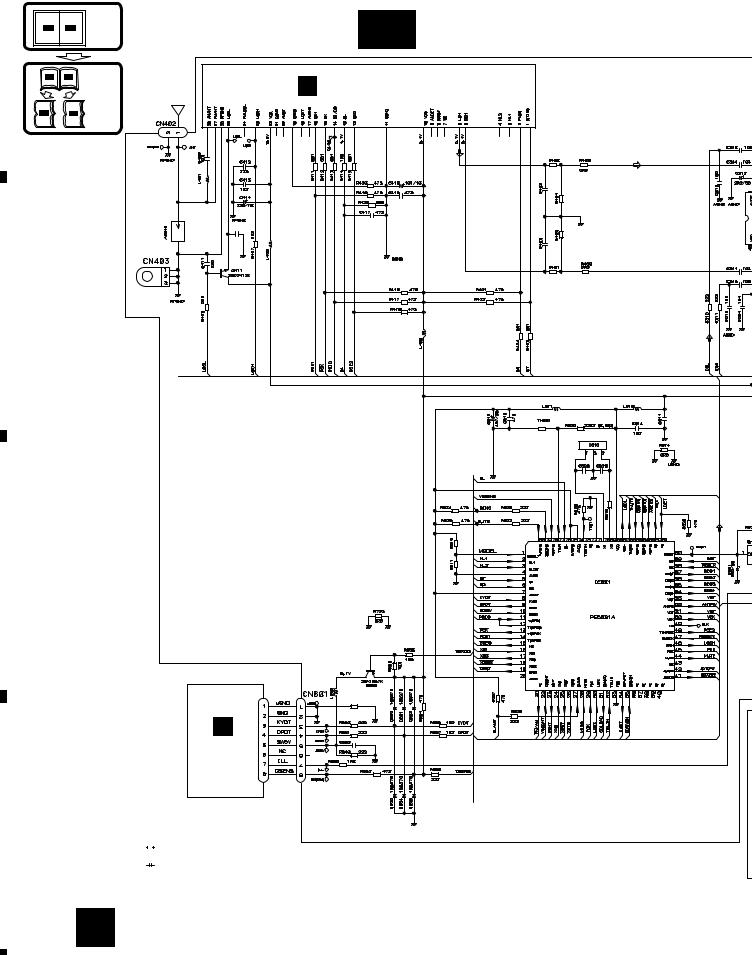
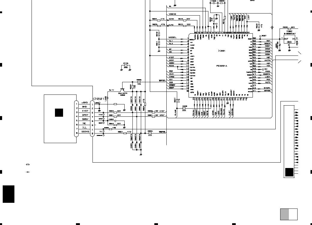
SYSTEM |
|
|
|
|
|
|
|
|
|
|
|
|
|
|
|
|
CONTROLLER |
|
|
|
|
|
|
|
|
|
|
|
|
|
|
|
|
|
|
IC 601(1/2) |
|
|
|
|
|
|
|
|
|
|
|
|
|
|
|
|
|
PE5091A |
|
|
|
|
|
|
|
|
|
|
|
|
|
|
|
6 |
SD |
|
|
|
|
|
|
|
|
|
|
|
|
|
|
|
|
|
|
|
|
|
|
|
|
|
|
|
|
|
|
|
|
|
|
76 |
SL |
|
|
|
|
|
|
|
|
|
|
|
|
|
|
|
|
14 |
TUNPCE |
|
|
|
|
|
|
|
|
|
|
|
|
|
|
|
|
13 |
TUNPCK |
|
|
|
|
|
|
|
|
|
|
|
|
|
|
|
|
48 |
TUNPCE2 |
|
|
|
|
|
|
|
|
|
|
|
|
|
|
|
|
|
|
|
|
|
|
|
|
|
|
|
|
|
|
|
|
|
|
12 |
TUNPDO |
|
|
|
|
|
|
|
|
|
|
|
|
|
|
|
PDIO |
11 |
|
|
|
|
|
|
|
|
|
|
|
|
|
|
|
|
TUNPDI |
VST |
|
|
|
|
|
|
|
|
|
Q353 |
|
|
|
||
|
|
|
|
|
|
|
|
|
|
|
|
|
|
|
|||
|
|
67 |
|
VCK |
|
|
|
|
|
|
|
|
|
|
|
|
|
|
|
LOCL |
VDT |
|
|
|
|
|
|
|
|
|
|
|
|
|
|
|
|
|
|
|
|
|
|
|
|
|
|
Q903 |
|
|
BACKUP |
|
|
|
|
|
|
|
|
|
|
|
|
|
|
VDD |
|
B.U |
|
|
|
|
|
|
|
|
|
|
|
|
|
|
|
|
B.U |
|
|
||
|
|
|
|
|
|
|
|
|
|
|
|
|
|
|
|
|
FUSE |
|
|
|
|
|
|
|
|
|
|
|
|
|
|
|
|
|
10A |
|
|
|
|
|
|
|
|
|
|
|
|
|
|
|
|
2 |
BACK UP |
|
|
|
|
|
|
|
|
|
|
|
|
|
|
|
|
1 |
GND |
|
|
|
|
|
VST/ VCK/ VDT |
|
|
|
|
|
|
|
|
|
|
GND |
|
|
|
2 |
IN1 |
|
|
|
|
|
POWER AMP |
|
|
|
|
|
|
||
|
|
|
|
|
|
|
|
|
|
|
|
|
|
|
|
|
|
|
|
|
|
ELECTRONIC VOLUME/ |
|
|
|
|
|
|
23 |
|
|
FL– |
9 |
FL– |
|
|
|
|
|
SOURCE SELECTOR |
|
19 |
|
|
|
|
|
|
|
FL+ |
|||
|
|
3 |
IN2 |
Fout |
|
14 |
FL |
IC 302 |
21 |
|
|
11 |
FL+ |
||||
|
|
|
IC 301 |
|
|
20 |
|
12 |
|
PAL005A |
3 |
|
|
RL– |
|
|
|
|
|
|
|
|
Rout |
|
RL |
|
|
10 |
RL– |
||||||
|
|
|
|
SN761029DL |
|
|
|
|
|
|
5 |
|
|
RL+ |
12 |
RL+ |
|
|
|
|
|
|
|
|
|
|
|
MUTE |
STBY |
B.REM |
|
|
|
|
|
|
|
|
TONout |
FADin |
|
|
|
|
|
22 |
4 |
25 |
|
|
|
|
|
|
|
|
17 |
18 |
|
|
|
|
|
|
|
|
|
|
|
|
|
EQ |
INPUT1 1 |
|
|
|
|
|
|
|
|
|
SYSPW |
|
|
|
|
|
|
P |
OUT1 9 |
|
|
|
|
|
|
|
|
|
|
|
|
|
|
|
|
|
|
|
|
|
|
|
|
|
|
|
|
|
|
|
|
|
|
|
|
|
|
|
|
|
|
|
Q351 MUTE |
|
|
|
Q902 |
|
|
|
|
|
|
|
|
|
|
|
|
|
|
|
|
|
|
|
|
|
|
|
|
|
|
|
|
|
|
|
|
|
|
|
asens |
|
ACC |
4 |
ACC |
|
|
|
|
|
|
|
|
|
|
|
|
|
|
|
|
||
|
|
|
|
|
|
|
|
|
|
|
|
|
bsens |
|
B.U |
|
|
|
|
|
|
|
63 |
|
|
|
|
|
|
|
|
|
|
|
|
|
|
|
|
ASENS |
|
|
|
|
|
|
|
|
|
|
|
|
|
|
|
|
|
|
|
|
|
|
|
|
|
|
Q901 |
|
|
|
|
|
|
|
|
|
|
|
|
|
|
|
|
|
|
|
|
|
|
|
|
|
|
BSENS |
64 |
|
|
|
|
|
|
|
|
|
|
|
|
|
|
|
|
|
|
|
|
|
|
|
|
|
|
|
|
|
|
|
|
|
|
SYSTEM |
|
|
|
|
|
|
|
|
|
|
|
|
|
|
|
|
CONTROLLER |
|
|
|
|
|
|
|
|
|
|
|
|
|
|
|
|
|
|
IC 601(2/2) |
|
|
|
|
|
|
|
|
|
|
|
|
|
|
|
|
|
PE5091A |
|
|
|
|
|
|
|
|
|
|
|
|
|
|
|
|
|
SYSPW |
42 |
|
|
|
|
|
|
|
|
|
B.REMOTE |
|
B.REMOTE |
|
|
31 |
CDLOAD |
|
|
|
|
|
|
|
|
|
|
5 |
|
||
|
|
|
|
|
|
|
|
|
|
|
|
|
|
|
|||
|
|
|
|
|
|
|
|
|
|
|
|
|
|
|
|
|
|
|
|
34 |
CDEJECT |
|
|
|
|
|
|
|
|
|
|
|
|
|
|
|
|
|
|
|
|
|
|
|
|
|
|
|
|
|
|
|
|
|
|
23 |
CONT |
|
|
|
|
|
|
|
|
|
|
|
|
|
|
|
|
|
|
|
|
|
|
|
|
|
|
|
|
|
|
|
|
|
|
80 |
|
MUTE |
44 |
|
|
|
|
|
C KEYBOARD UNIT |
|
|
|
|
||
|
|
EJTSNS |
|
|
|
|
|
|
|
|
|
|
|||||
|
|
|
|
|
|
|
|
|
|
|
|
|
|
||||
|
|
79 |
DSCSNS |
|
|
|
|
|
|
|
|
|
|
|
|||
|
|
27 |
CLAMP |
|
|
|
|
|
|
|
|
|
|
|
|
|
|
|
|
|
|
|
|
|
|
|
|
|
|
|
|
|
|
|
|
|
|
|
|
|
|
|
|
|
|
CN601 |
CN1801 |
|
|
|
|
|
|
|
|
|
|
|
|
|
|
|
|
|
|
|
|
|
|
|
|
|
|
22 |
|
KYDT |
8 |
|
|
|
|
3 |
3 |
20 |
KYDT |
|
LCD |
|
|
|
|
VDCONT |
DPDT |
9 |
|
|
|
|
4 |
4 |
18 DPDT |
|
|
|
|||
|
|
|
|
|
|
RESET |
|
|
|
|
|||||||
|
|
|
|
|
|
|
|
|
|
|
|
|
|
|
|
|
|
|
|
|
|
|
60 |
|
1 |
IC 602 |
2 |
|
|
|
|
|
|
|
|
|
|
|
|
RESET |
|
|
|
S–80834ANY |
VDD |
|
|
|
|
|
|
|
|
|
|
VDD |
|
|
|
|
|
5 |
5 |
50 VDD |
|
|
|
41 |
|
10 VLCD |
|
35 |
SWVDD |
Q650 |
|
LCD DRIVER |
|
CD5VON |
|
|
|||
|
|
|
|
|
|
|
|
|
|
IC 1801 |
|
|
|
|
|
PD6293A |
|
|
|
|
|
KEY MATRIX |
|
|
|
|
|
22 |
23 |
|
|
|
|
X1801 |
|
9
|
5 |
|
6 |
|
7 |
|
8 |
|
|
|
|
||||
|
|
|
|
B
C
D
|
1 |
|
2 |
|
3 |
|
4 |
|
|
|
|
|
|
DEH-2150,1150
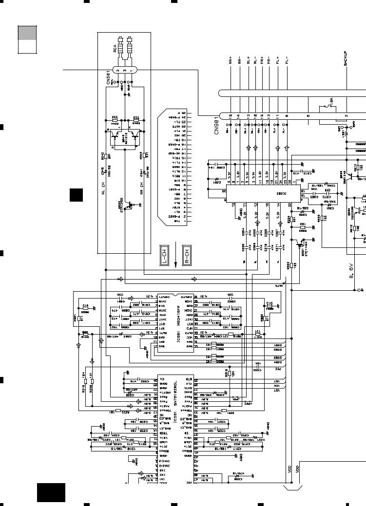
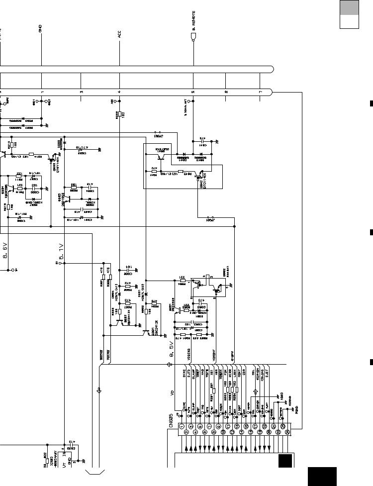
3.2 OVERALL CONNECTION DIAGRAM(GUIDE PAGE)
Note: When ordering service parts, be sure to refer to “EXPLODED VIEWS AND PARTS LIST” or “ELECTRICAL PARTS LIST”.
|
|
Large size |
A-a |
A-b |
SCH diagram |
|
||
A |
|
|
A-a |
A-b |
Guide page |
A-a |
A-b |
Detailed page |
B
C
D
10 A
1
A-a
B FM/AM TUNER UNIT
FM(100%):-19.5dBs
AM (30%):-30dBs
CD:+4.
FM(100%):-19
AM (30%):-30
|
272 |
|
|
183 |
|
201M-DSP -S00B |
|
162 |
183 |
162 |
|
|
C499 |
|
|
103 |
|
|
272 |
|
104
4.194304MHz
CSS1023
150 150
682
R
393 (DEH-2150) |
102 (DEH-1150) |
183 (DEH-2150)
SYSTEM CONTROLLER
R699 0R0
C
KEYBOARD |
104 |
UNIT |
|
NOTE : |
|
|
|
||
|
|
Symbol indicates a resistor. |
For resistors and capacitors in the circuit diagrams, their resistance values or |
|
|
|
|
|
|||
|
|
No differentiation is made between chip resistors and |
|
||
|
|
discrete resistors. |
capacitance values are expressed in codes: |
|
|
|
|
|
|||
|
|
Symbol indicates a capacitor. |
|
|
|
|
|
No differentiation is made between chip capacitors and |
Ex. *Resistors |
|
|
|
|
discrete capacitors. |
Code |
Practical value |
|
The > mark found on some component parts indicates |
123 |
12k ohms |
|
||
the importance of the safety factor of the part. |
103 |
10k ohms |
|
||
Therefore, when replacing, be sure to use parts of |
|
|
|
||
identical designation. |
*Capacitors |
|
|||
|
|
|
Code |
Practical value |
|
|
|
|
103 |
0.01 F |
|
|
|
|
101/10 |
100 F/10V |
|
|
2 |
|
3 |
|
4 |
|
|
|
|
|
|||
|
|
|
|
|
5 |
|
6 |
|
7 |
|
8 |
|
|
|
|
|
|
DEH-2150,1150
CD:+10.1dBs
FM(100%):+3.5dBs
AM (30%):-7dBs
.1dBs
9.5dBs
0dBs
SOURCE SELECTOR/
E.VOL
Reset
DEH-2150
(DEH-1150)
D.EQ
(DEH-1150)
A-b
A TUNER AMP ASSY
DEH-2150 |
|
POWER AMP |
332/16 (DEH-1150) |
CD:+10.1dBs |
|
472/16 (DEH-2150) |
PAL005A(45W)(DEH-2150) TDA7384(35W)(DEH-1150) |
|
|
FM(100%):+3.5dBs |
|
|
AM (30%):-7dBs |
|
|
|
|
2150)-(DEH |
CD:+36.1dBs |
FM(100%):+29.5dBs
AM (30%):+19dBs
>
CEK1136
600 H
(B2)

A
B
C
D CD MECHANISM MODULE
DEH-1150
(DEH-2150)
(DEH-1150)
VD REGULATOR
CD:+4.1dBs
D
A 11
|
5 |
|
6 |
|
7 |
|
8 |
|
|
|
|
|
|
||||
|
|
|
|
|
1 |
|
2 |
DEH-2150,1150 |
|
|
A-a A-b |
CD:+4.1dBs FM(100%):-19.5dBs AM(30%):-30dBs |
SOURC E.VOL |
A |
|
|
|
162 |
162 |
272 |
183 |
183 |
|
B
AM (30%):-30dBs
FM(100%):-19.5dBs
C |
TUNER UNIT |
||
FM/AM |
|||
|
|
||
|
|
|
|
|
|
B |
|
|
|
|
|
|
|
|
|
C499 |
103 |
D
DSP-201M-S00B
12 A-a
3 |
4 |
|
1 |
104
4.194304MHz |
CSS1023 |
150 150 |
272
|
1 |
|
2 |
|
3 |
|
4 |
|
|
|
|
|
|
||||
|
|
|
|
|
5
6
7
13 a-A 8
C
KEYBOARD
UNIT
NOTE :
Symbol indicates a resistor.
No differentiation is made between chip resistors and discrete resistors.
Symbol indicates a capacitor.
No differentiation is made between chip capacitors and discrete capacitors.
The > mark found on some component parts indicates the importance of the safety factor of the part. Therefore, when replacing, be sure to use parts of identical designation.
150 150
682
393 (DEH-2150) |
102 (DEH-1150) |
183 (DEH-2150)
SYSTEM CONTROLLER
R699 0R0
104
For resistors and capacitors in the circuit diagrams, their resistance values or capacitance values are expressed in codes:
Ex. *Resistors |
|
Code |
Practical value |
123 |
12k ohms |
103 |
10k ohms |
*Capacitors |
|
Code |
Practical value |
103 |
0.01 F |
101/10 |
100 F/10V |
Reset
5
 2
2
|
|
6 |
MECHANISM MODULE |
|
7 |
CD |
|
|
D |
2150,1150-DEH |
|
A-a A-b |
8 |
|
|
|
D |
C |
B |
A |
|
1 |
|
2 |
DEH-2150,1150 |
|
|
|
A-b |
|
|
|
A-a |
|
|
|
A |
|
|
|
|
TUNER AMP ASSY |
|
|
B |
A |
|
|
|
|
|
|
|
DEH-2150 |
|
|
C |
-2150 |
|
|
DEH |
|
D.EQ |
|
|
|
||
|
(DEH-1150) |
|
|
|
CD:+10.1dBs FM(100%):+3.5dBs AM (30%):-7dBs |
|
SELECTOR/SOURCE |
D |
.1dBs |
9.5dBs 0dBs |
|
|
|
|
|
14 |
A-b |
|
|
|
1 |
|
2 |
3 |
|
4 |
|
|
|
(DEH-1150) |
(DEH-2150) |
|
332/16 |
||
472/16 |
||
AMP |
||
|
||
POWER |
TDA7384(35W)(DEH-1150) |
|
|
PAL005A(45W)(DEH-2150) |
|
|
CD:+10.1dBs FM(100%):+3.5dBs AM (30%):-7dBs |
(DEH-1150)
E.VOL
3
AM (30%):+19dBs
FM(100%):+29.5dBs
CD:+36.1dBs
> |
CEK1136 |
600 H
(DEH-2150)
1
4
|
5 |
|
6 |
|
7 |
|
8 |
|
|
|
|
|
|
600 H
(DEH-2150)
DEH-1150
DEH-2150,1150
A-a A-b
A
B
(B2)
(DEH-1150)
Reset
2
VD REGULATOR |
C |
|
|
CD:+4.1dBs |
|
|
D |
DCDMECHANISMMODULE |
|
A-b 15
|
5 |
|
6 |
|
7 |
|
8 |
|
|
|
|
|
|
||||
|
|
|
|
|
|
1 |
|
2 |
|
3 |
|
4 |
|
|
|
|
|
|
DEH-2150,1150
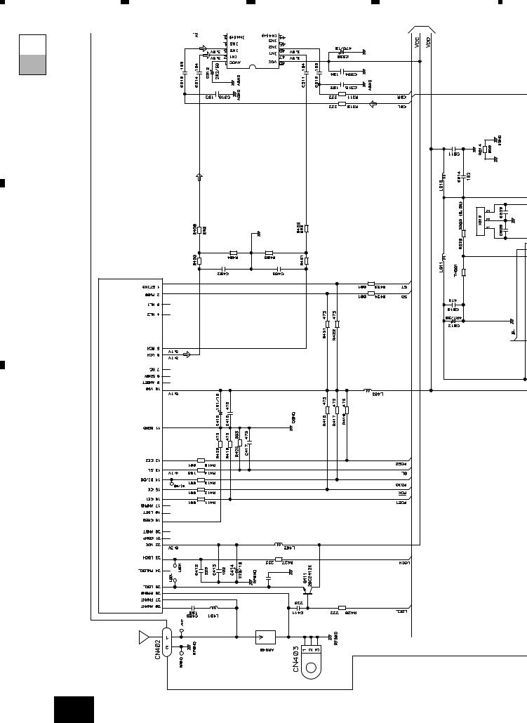
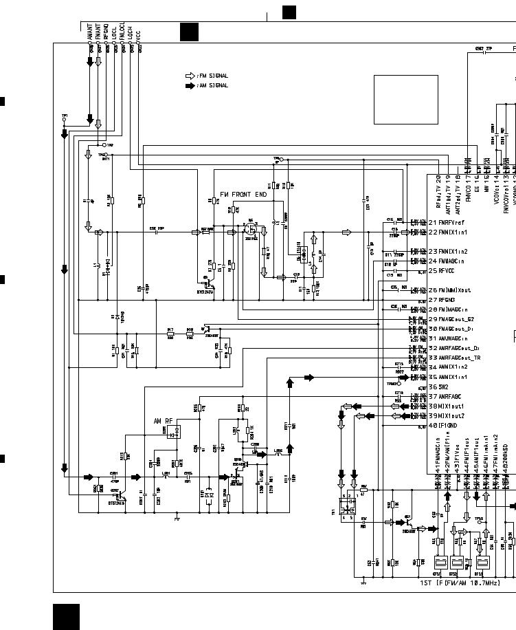
3.3 FM/AM TUNER UNIT
A  A
A
B FM/AM TUNER UNIT
Mark |
Band |
Input Level |
None |
– |
– |
F0 |
FM |
0dBf |
F65 |
FM |
65dBf |
F125 |
FM |
125dBf |
A0 |
AM |
0dB |
A74 |
AM |
74dB |
A125 |
AM |
125dB |
B
KV1410(23)
C
DAN217U |
 DAN217U
D
16 B
|
1 |
|
2 |
|
3 |
|
4 |
|
|
|
|
|
|
||||
|
|
|
|
|

|
5 |
|
6 |
|
7 |
|
8 |
|
|
|
|
|
|
DEH-2150,1150
A
KV1410(23)
B
C
D
B 17
|
5 |
|
6 |
|
7 |
|
8 |
|
|
|
|
|
|
||||
|
|
|
|
|
|
1 |
|
2 |
|
3 |
|
4 |
|
|
|
|
|
|
DEH-2150,1150
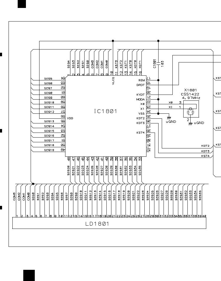
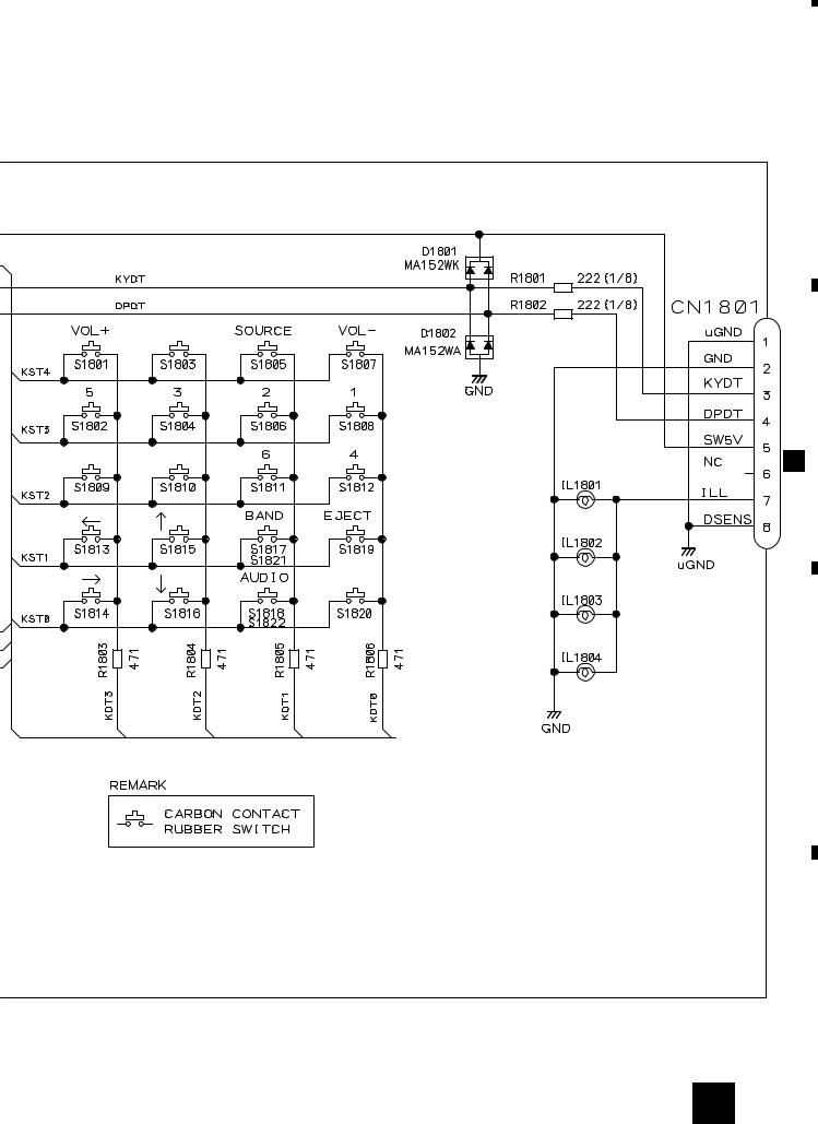
3.4 KEYBOARD UNIT
C KEYBOARD UNIT
A
B
PD6293A
LCD DRIVER,
KEY CONTROLLER
C
CAW1560
D
18 C
|
1 |
|
2 |
|
3 |
|
4 |
|
|
|
|
|
|
||||
|
|
|
|
|
|
5 |
|
6 |
|
7 |
|
8 |
|
|
|
|
DEH-2150,1150
EQ, LOUD
CLK LOCAL
BSM
A CN601
A
B
C
IL1801-1804 : CEL1547(14V 40mA)
D
C 19
|
5 |
|
6 |
|
7 |
|
8 |
|
|
|
|
|
|
||||
|
|
|
|
|
|
1 |
|
2 |
|
3 |
|
4 |
|
|
|
|
|
|
DEH-2150,1150
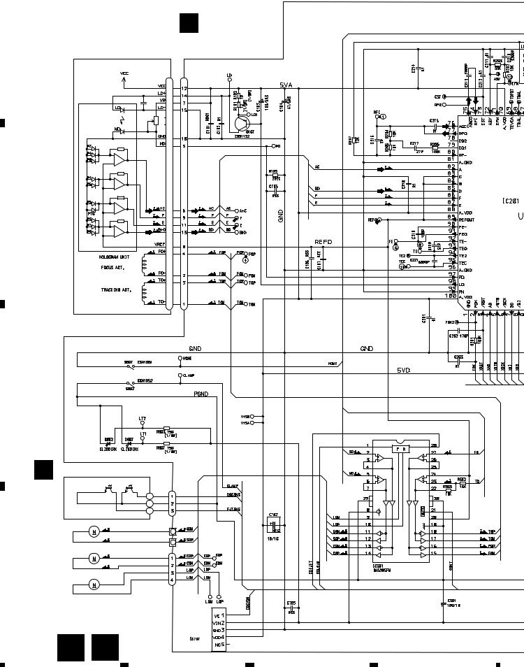
3.5 CD MECHANISM MODULE
D CONTROL UNIT
A
PICKUP UNIT (SERVICE)(P8)
CN101
B
RF-AMP, S
C
E |
PHOTO UNIT(S8) |
CN802 |
D
Q1 CPT230SX-TU Q2 CPT230SX-TU
SPINDLE MOTOR
M3 CXB2562
CARRIAGE MOTOR
M1 CXB2190
LOADING MOTOR
CD DRIVER
M2 CXB2195
CN801
20 D |
E |
BA05SFP |
5V REGULATOR |
|
|
|
|
||
|
|
|
|
|
1 |
2 |
|
3 |
4 |
|
5 |
|
6 |
|
7 |
|
8 |
|
|
|
|
|
|
DEH-2150,1150
A
SWITCHES:
CONTROL UNIT
S801 : HOME SWITCH.....ON-OFF
S802 : CLAMP SWITCH....ON-OFF
The underlined indicates the switch position.
B
MP, SERVO, DSP, DAC, LPF
CN701
C
A CN605
D
D 21
|
5 |
|
6 |
|
7 |
|
8 |
|
|
|
|
|
|
||||
|
|
|
|
|
 Loading...