

Page 1
ORDER NO.
2013
• The only difference in appearance between the "DDJ-WEGO2/XE5" and
"DDJ-WEGO2/XE25" is the printing on the serial-number labels (the suffix being either
"/XE5" or "/XE25").
Their service parts are exactly the same.
RRV4498
DDJ-WEGO2-K
DJ Controller
DDJ-WEGO2-K
THIS MANUAL IS APPLICABLE TO THE FOLLOWING MODEL(S) AND TYPE(S).
Model Type Power Requirement Remarks
DDJ-WEGO2-K XE5 DC 5 V (USB-bus power only)
DDJ-WEGO2-K XE25 DC 5 V (USB-bus power only)
DDJ-WEGO2-K XECN5 DC 5 V (USB-bus power only)
DDJ-WEGO2-R XE5 DC 5 V (USB-bus power only)
DDJ-WEGO2-R XE25 DC 5 V (USB-bus power only)
DDJ-WEGO2-R XECN5 DC 5 V (USB-bus power only)
DDJ-WEGO2-W XE5 DC 5 V (USB-bus power only)
DDJ-WEGO2-W XE25 DC 5 V (USB-bus power only)
DDJ-WEGO2-W XECN5 DC 5 V (USB-bus power only)
PIONEER CORPORATION 1-1, Shin-ogura, Saiwai-ku, Kawasaki-shi, Kanagawa 212-0031, Japan
PIONEER ELECTRONICS (USA) INC. P.O. Box 1760, Long Beach, CA 90801-1760, U.S.A.
PIONEER EUROPE NV Haven 1087, Keetberglaan 1, 9120 Melsele, Belgium
PIONEER ELECTRONICS ASIACENTRE PTE. LTD. 253 Alexandra Road, #04-01, Singapore 159936
PIONEER CORPORATION
K-MZV NOV.
2013 Printed in Japan
Page 2

1
WARNING
This product may contain a chemical known to the State of California to cause cancer, or birth defects or other reproductive
harm.
Health & Safety Code Section 25249.6 - Proposition 65
This service manual is intended for qualified service technicians; it is not meant for the casual do-it-
yourselfer. Qualified technicians have the necessary test equipment and tools, and have been trained
to properly and safely repair complex products such as those covered by this manual.
Improperly performed repairs can adversely affect the safety and reliability of the product and may
void the warranty. If you are not qualified to perform the repair of this product properly and safely, you
should not risk trying to do so and refer the repair to a qualified service technician.
2 3 4
SAFETY INFORMATION
A
B
C
D
E
F
2
1
2 3 4
DDJ-WEGO2-K
Page 3

5
6 7 8
CONTENTS
SAFETY INFORMATION.......................................................................................................................................................... 2
1. SERVICE PRECAUTIONS ....................................................................................................................................................4
1.1 NOTES ON SOLDERING............................................................................................................................................... 4
1.2 SERVICE NOTICE.......................................................................................................................................................... 4
2. SPECIFICATIONS .................................................................................................................................................................5
3. BASIC ITEMS FOR SERVICE ..............................................................................................................................................6
3.1 CHECK POINTS AFTER SERVICING ........................................................................................................................... 6
3.2 JIGS LIST .......................................................................................................................................................................6
3.3 PCB LOCATIONS ........................................................................................................................................................... 7
4. BLOCK DIAGRAM ................................................................................................................................................................8
4.1 OVERALL WIRING DIAGRAM .......................................................................................................................................8
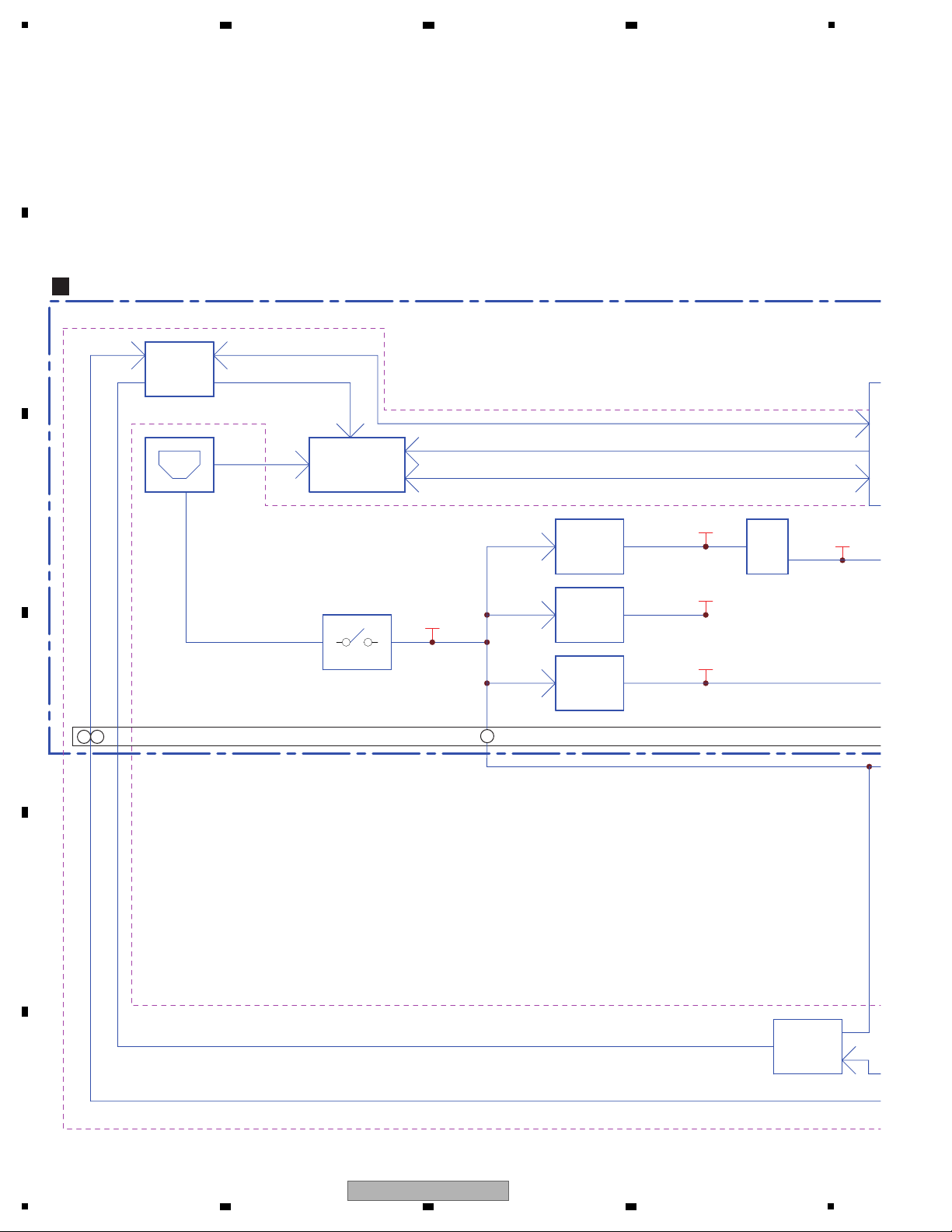
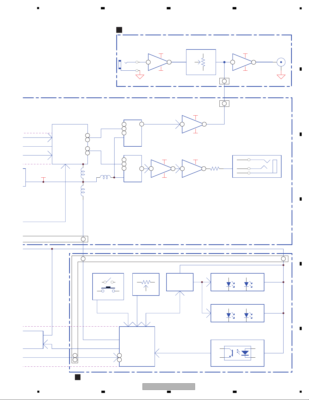
4.2 OVERALL BLOCK DIAGRAM....................................................................................................................................... 10
5. DIAGNOSIS ........................................................................................................................................................................ 12
5.1 BOOT SEQUENCE....................................................................................................................................................... 12
5.2 TROUBLESHOOTING.................................................................................................................................................. 13
5.3 OPERATION CHECK WITH VIRTUAL DJ....................................................................................................................15
6. SERVICE MODE................................................................................................................................................................. 17
6.1 FIRMWARE VERSION (MAIN UCOM) and LAST MEMORY CONFIRMATION MODE...............................................18
6.2 BUTTON INPUT and DISPLAY FUNCTION CONFIRMATION MODE .........................................................................20
6.3 JOG DIAL ROTATION TIME MEASUREMENT MODE................................................................................................. 23
6.4 FACTORY RESET MODE............................................................................................................................................. 24
6.5 iPhone/iPad CONNECTING CABLE CONFIRMATION MODE ....................................................................................25
7. DISASSEMBLY ................................................................................................................................................................... 26
8. EACH SETTING AND ADJUSTMENT................................................................................................................................ 31
8.1 NECESSARY ITEMS TO BE NOTED........................................................................................................................... 31
8.2 UPDATING OF THE FIRMWARE ................................................................................................................................. 31
8.3 ITEMS FOR WHICH USER SETTINGS ARE AVAILABLE........................................................................................... 32
9. EXPLODED VIEWS AND PARTS LIST............................................................................................................................... 34
1 PACKING SECTION ..................................................................................................................................................... 34
9.
9.2 EXTERIOR SECTION .................................................................................................................................................. 36
10. SCHEMATIC DIAGRAM .................................................................................................................................................... 40
10.1 CONTROL PCB ASSY ...............................................................................................................................................40
10.2 IO PCB ASSY ............................................................................................................................................................. 42
10.3 MASTER PCB ASSY.................................................................................................................................................. 44
10.4 WHELL (R) and (L) PCB ASSYS................................................................................................................................ 46
10.5 WAVEFORMS.............................................................................................................................................................48
11. PCB CONNECTION DIAGRAM........................................................................................................................................ 52
11.1 CONTROL PCB ASSY ...............................................................................................................................................52
11.2 IO PCB ASSY ............................................................................................................................................................. 56
11.3 MASTER PCB ASSY.................................................................................................................................................. 58
11.4 WHELL (R) PCB ASSY .............................................................................................................................................. 59
11.5 WHEEL (L) PCB ASSY...............................................................................................................................................60
12. PCB PARTS LIST .............................................................................................................................................................. 61
A
B
C
D
E
F
DDJ-WEGO2-K
5
6 7 8
3
Page 4

1
• For environmental protection, lead-free solder is used on the printed circuit boards mounted in this unit.
Be sure to use lead-free solder and a soldering iron that can meet specifications for use with lead-free solders for repairs
accompanied by reworking of soldering.
• Compared with conventional eutectic solders, lead-free solders have higher melting points, by approximately 40 ºC.
Therefore, for lead-free soldering, the tip temperature of a soldering iron must be set to around 373 ºC in general, although
the temperature depends on the heat capacity of the PC board on which reworking is required and the weight of the tip of
the soldering iron.
Do NOT use a soldering iron whose tip temperature cannot be controlled.
Compared with eutectic solders, lead-free solders have higher bond strengths but slower wetting times and higher melting
temperatures (hard to melt/easy to harden).
The following lead-free solders are available as service parts:
• Parts numbers of lead-free solder:
GYP1006 1.0 in dia.
GYP1007 0.6 in dia.
GYP1008 0.3 in dia.
If a user complains about a failure of the unit when it is used with an iPhone/iPad, follow the diagnostic procedure
described below.
1. Check that the iOS device recognizes the DDJ-WEGO2.
(For details, see "1. Before confirmation in this mode" in "6.5 iPhone/iPad CONNECTING CABLE CONFIRMATION MODE.")
2. Check if the supplied iPhone/iPad connecting cable is okay in iPhone/iPad Connecting Cable Confirmation mode.
3. Check if the DDJ-WEGO2 is okay. To do so, check operation of each operating element or LED in Service mode and check
the output signals and operations on the PC (with Virtual DJ LE installed).
Basically, if both the iPhone/iPad connecting cable and the DDJ-WEGO2 are okay, the problem is on the connected iOS device
side.
[iOS devices usable with this unit]
• iOS
iOS6
• Models supporting the iPhone/iPad connecting cable (Lightning)
iPad (4th generation), iPad mini, iPhone5, iPod touch (5th generation)
For the latest information on the supported iOS devices, visit the Pioneer DJ support site indicated below, and refer to
"DDJ-WeGO2." http://pioneerdj.com/support/
Diagnostic procedure for failure when the unit is used with an iPhone/iPad
This product is provided with a mode in which the brightness of LED illumination of the Jog dials on the right and left decks
automatically changes at a slow pace. This mode can be used for mood lighting.
Regardless of whether the DJ application (Virtual DJ LE) is running on the PC or not, if no operation is performed on this unit
within 10 minutes, or press the DECK C/D button while pressing the SHIFT button, Mood lighting mode is automatically entered
To return to the normal operation mode, operate any button other than the SHIFT or DECK C/D buttons or JOG dial or operate
any control of this unit.
On Mood lighting mode
2 3 4
1. SERVICE PRECAUTIONS
1.1 NOTES ON SOLDERING
A
B
C
1.2 SERVICE NOTICE
D
E
F
4
1
2 3 4
DDJ-WEGO2-K
Page 5
5
General – Main Unit
Power supply..........................................................................DC 5 V
Power consumption ...............................................................500 mA
Main unit weight (with iPhone/iPad stand mounted).... 1.8 kg (4.0 lb)
Maximum external dimensions (with iPhone/iPad stand mounted)
................380 mm (width) × 65 mm (height) × 250.6 mm (depth)
(14.96 in. (width) × 2.56 in. (height) × 9.87 in. (depth))
Tolerable operating temperature. +5 °C to +35 °C (+41 °F to +95 °F)
Tolerable operating humidity............. 5 % to 85 % (no condensation)
Audio Section
Rated output level
MASTER OUT...................................................................+13 dBu
Total harmonic distortion
MASTER OUT................................................................... 0.006 %
Frequency characteristic
MASTER OUT.......................................................20 Hz to 20 kHz
S/N ratio (when playing on computer)
MASTER OUT.......................................... 101 dB (at rated output)
Input impedance
MIC........................................................................................ 10 kΩ
Output impedance
MASTER OUT.........................................................................1 kΩ
PHONES ............................................................................... 4.7 Ω
USB AUDIO.............................24 bit/Fs: 44.1 kHz, 24 bit/Fs: 48 kHz
Input / Output terminals
USB terminal
B type
..................................................................................... 1 set
MASTER OUT output terminal
RCA pin jacks......................................................................... 1 set
PHONES output terminal
Stereo phone jack (Ø 6.3 mm) ............................................... 1 set
Stereo mini phone jack (Ø 3.5 mm)........................................ 1 set
MIC input terminal
Phone jack (Ø 6.3 mm)........................................................... 1 set
iOS device connection terminal
14-pin...................................................................................... 1 set
• VIRTUAL DJ LE software/driver software/operating instructions
CD-ROM
• USB cable
(408-SUB-132)
• Read Before Use (Important)/Quick Start Guide
(XE5, XE25: 502-WG2A-3328A, 502-WG2A-3329A)
(XECN5: 502-WG2B-3330)
• Warranty (for some regions)
The included warranty is for the European region.
— For the North American region, the corresponding information
isprovided on the last page of both the English and French
versions of the “Read Before Use (Important)/Quick Start
Guide”.
— For the Japanese region, the corresponding information is
provided on the last page of the Japanese version of the
“Read Before Use (Important)/Quick Start Guide”.
• iPhone/iPad connection cable (Lightning)
(408-WG2-129)
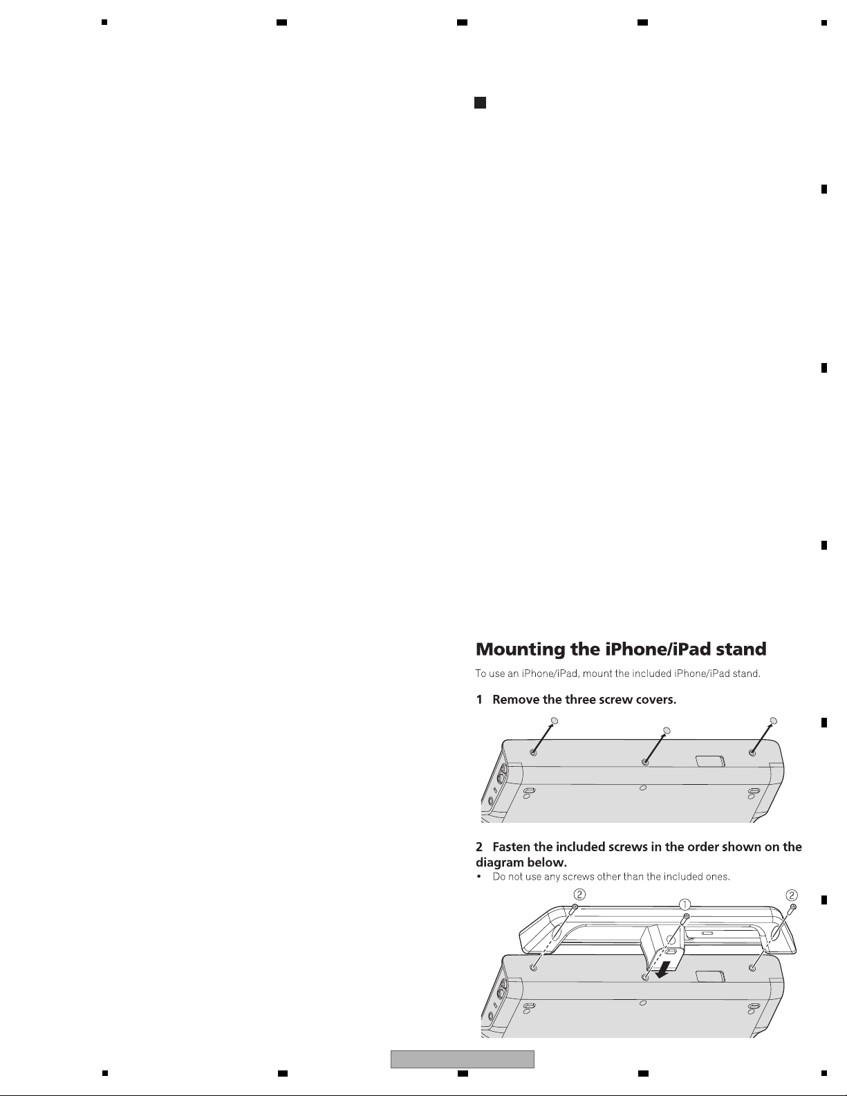
• iPhone/iPad stand
(DDJ-WEGO2-K: 701-WG2K-5403)
(DDJ-WEGO2-R: 701-WG2R-5403)
(DDJ-WEGO2-W: 701-WG2-5403)
•
Stand fixing screws x 3
(DDJ-WEGO2-K, DDJ-WEGO2-R: 602-SWISO415-745B)
(DDJ-WEGO2-W: 602-SWISO415-745Z)
• VIRTUAL DJ LE license key (indicated on this unit’s bottom panel)
Accessories
2. SPECIFICATIONS
6 7 8
A
B
C
D
E
F
DDJ-WEGO2-K
5
6 7 8
5
Page 6
1
Items to be checked after servicing
To keep the product quality after servicing, confirm recommended check points shown below.
Distortion
Noise
Volume too low
Volume too high
Volume fluctuating
Sound interrupted
See the table below for the items to be checked regarding audio.
No. Procedures
Item to be checked regarding audio
Check points
7 Check the appearance of the product. No scratches or dirt on its appearance after receiving it for service.
3 Confirmation of operation of operating elements and LEDs. Each confirmation items work with service mode normally.
1 Check the firmware version. The firmware version must be the latest one.
If it is not the latest one, be sure to update it.
2 Confirm that the customer complaint has been resolved.
If the problem pointed out by the customer occurs with a specific
source or operation, such as PC input, AUX/MIC input, Fader, or
Volume, input that specific source then perform that specific
operation for checking.
The customer complain must not be reappeared.
Audio and operations must be normal.
4 Check the analog audio output.
Connect this unit with a PC with the DJ application (Virtual DJ LE)
installed, via USB, then operate the DJ application (Virtual DJ LE).
There must be no errors, such as noise, in audio signals and
operations of the MASTER/HEADPHONES outputs.
5 Check the analog audio input.
Input an audio signal via AUX/MIC.
Audio and operations must be normal.
6 Check whether the connection with the iOS device (iPhone or
iPad) does not have a problem.
Confirmation work with service mode normally.
Lubricants and Glues List
Name Part No. Remarks
Grease GEM1096 Refer to “7. DISASSEMBLY”. DAIZO NICHIMOLY NEW-SL PS-70
Adhesive GYL1001 Refer to “7. DISASSEMBLY”.
Adhesive GYL1005 Refer to “7. DISASSEMBLY”.
Jigs List
Jig Name Part No. Purpose of use / Remarks
USB cable GGP1193 for PC connection
iPhone/iPad connection cable (Lightning) GGP1234 for iOS device connection
2 3 4
3. BASIC ITEMS FOR SERVICE
3.1 CHECK POINTS AFTER SERVICING
A
B
C
D
3.2 JIGS LIST
E
F
6
1
2 3 4
DDJ-WEGO2-K
Page 7
5
CONTROL PCB ASSY 704-WG2-A604
IO PCB ASSY 704-WG2-A607
MASTER PCB ASSY 704-WG2-A608
WHEEL (R) PCB ASSY 704-WG2-A609
WHEEL (L) PCB ASSY 704-WG2-A610
Mark No. Description Part No.
LIST OF ASSEMBLIES
NOTES: - Parts marked by “NSP” are generally unavailable because they are not in our Master Spare Parts List.
-
The > mark found on some component parts indicates the importance of the safety factor of the part.
Therefore, when replacing, be sure to use parts of identical designation.
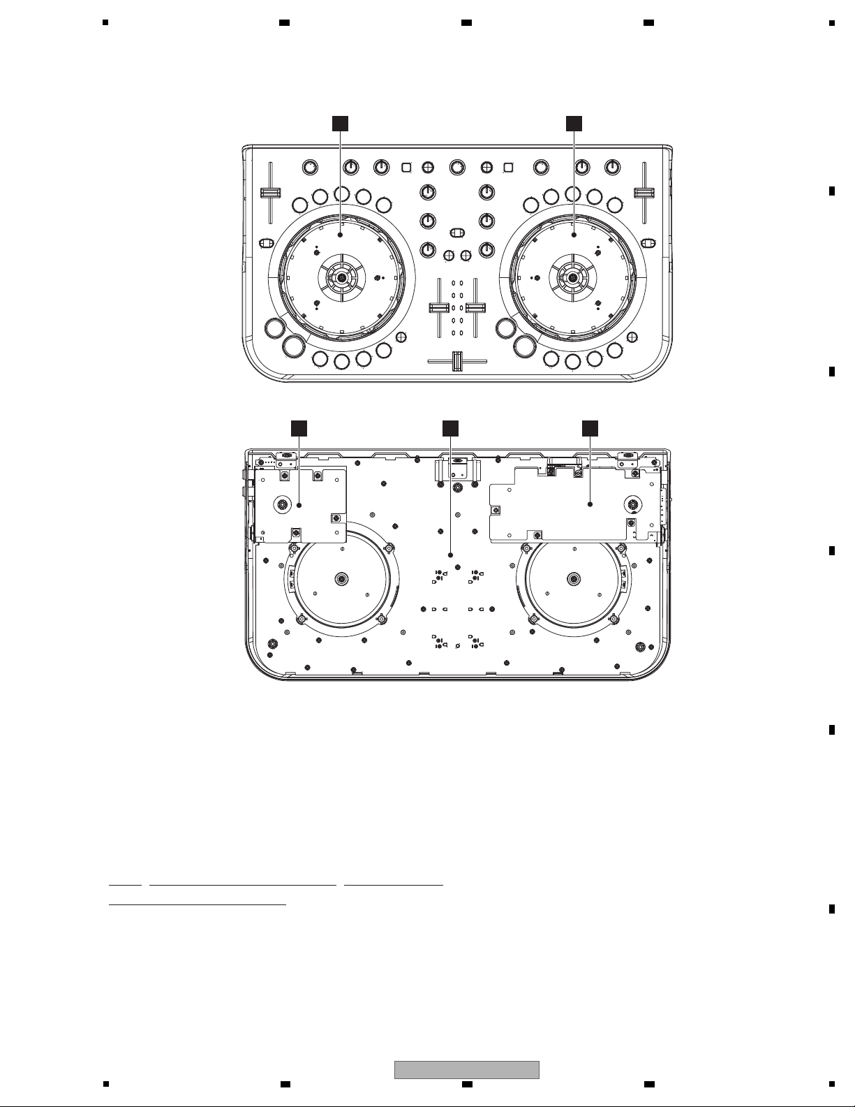
D
WHEEL (R) PCB ASSY
E
WHEEL (L) PCB ASSY
B
IO PCB ASSY
A
CONTROL PCB ASSY
C
MASTER PCB ASSY
• Bottom view
3.3 PCB LOCATIONS
6 7 8
A
B
C
D
E
F
DDJ-WEGO2-K
5
6 7 8
7
Page 8
1
CONTROL PCB ASSY
(704-WG2-A604)
A
E
WHEEL (L) PCB ASSY
(704-WG2-A610)
B
IO PCB ASSY
(704-WG2-A607)
C
MASTER
(704-WG2
1
2
3
4
5
CN605
W604
CN02B
CN501
CN01B
W501
CN604
CN01A
CN605A
FGND
FGND
AGND
ISCL
ISDA
ISDA
ISCL
G5
W02A
W01A
W02B
W01B
CHASSIS 1
G2
W3B
W4B
W3A
W4A
G1A
G1B
IN1
CN02A
2 3 4
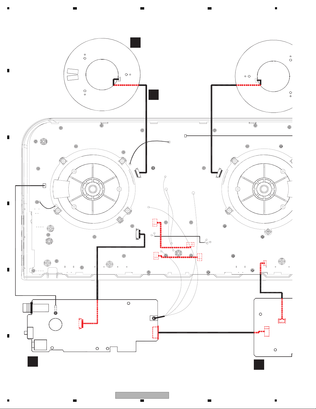
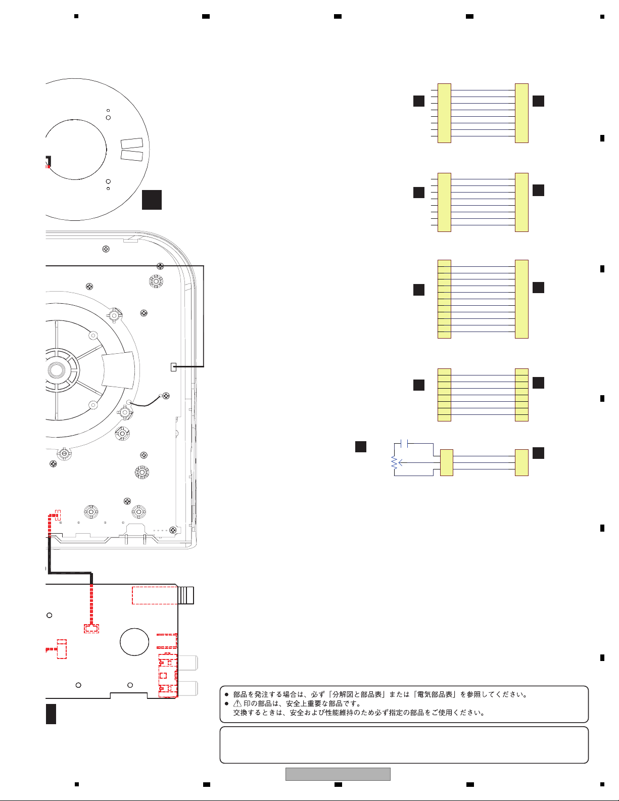
4. BLOCK DIAGRAM
4.1 OVERALL WIRING DIAGRAM
A
B
C
D
E
F
8
1
DDJ-WEGO2-K
2 3 4
Page 9
5
11
10
9
8
7
6
5
4
3
2
1
MI C VOL
31
2
VR621
20K B
1
2
3
C692
10/25
1
2
3
4
5
6
7
8
9
10
11
ISDA
ISCL
5V
GND
A5V
PMUTE
REST
INT
SCL
DGND
SDA
1
2
3
4
5
6
7
1
2
3
4
5
6
7
-6.5V
L
AGND
R
6.5V
FGND
1
2
3
1
2
3
4
5
6
7
8
FFC 8P FFC 8P
FFC 8P
FFC 11P FFC 11P
FFC 8P
1
2
3
4
5
6
7
8
WL 1A
WL 1B
DS1
STCP 5
SHCP 1
PWM1
5V
DGND
1
2
3
4
5
6
7
8
1
2
3
4
5
6
7
8
WL 1A
WL 1B
DS1
STCP 5
SHCP 1
PWM1
5V
DGND
CN01A CN01B
CN02A CN02B
CN605 CN605A
W501 CN501
CN604
W604
-
When ordering service parts, be sure to refer to "EXPLODED VIEWS and PARTS LIST" or "PCB PARTS LIST".
-
The > mark found on some component parts indicates the impor tance of the safety factor of the part.
Therefore, when replacing, be sure to use parts of identical designation.
A
CONTROL
PCB ASSY
A
CONTROL
PCB ASSY
E
WHEEL (L)
PCB ASSY
D
WHEEL (R)
PCB ASSY
A
CONTROL
PCB ASSY
A
CONTROL
PCB ASSY
C
MASTER
PCB ASSY
B
IO
PCB ASSY
B
IO
PCB ASSY
C
MASTER
PCB ASSY
D
WHEEL (R) PCB ASSY
(704-WG2-A609)
MASTER PCB ASSY
(704-WG2-A608)
1
2
3
4
5
W501
CN604
CHASSIS 2
IN2
6 7 8
A
B
C
D
E
F
5
6 7 8
DDJ-WEGO2-K
9
Page 10
1
12
POWER SW.
USB5V
-6.5V
3.3V
DC/DC
90%
DC/DC
90%
DC/DC
90%
6.5V
LDO
5V
LDO5V
USB signal switch
TS3USB30E
PC USB signal
Control
iOS: Accessory power(8P)/Accessory Identufy(30P)/Accessory Detect(30P)/Apple device detect(30P)
I2C: iPad authentication
iPad USB signal
WALTA 14pin
Connector
MOS FET
MOS FET
Authentication chip VDD
PC or iPad USB signal
USB Vbus
B
IO PCB ASSY
IC901
IC2
IC10
IC1
CN605A
9
1110
4.2 OVERALL BLOCK DIAGRAM
A
B
2 3 4
C
D
E
F
10
1
2 3 4
DDJ-WEGO2-K
Page 11
5
PHONES
AMP
4580
TUSB3200
DAC
PCM1755
24BIT
DAC
PCM1755
24BIT
-6.5V
6.5V
USB Controller
LM4917
31
2
12
KEYS & ENCODER
VR & FADERS
UI CPU
LED
DRIVER
INDICATORS LED
STM8S207MB
A
K
C
E
WHEEL
AMP
4580
-6.5V
6.5V
4.7 OHM
3.3V
LDO5V
WHEEL LED
vice detect(30P)
MOS FET
A
CONTROL PCB ASSY
IC600
IC501
IC300
IC200
IC301
IC201
IC302
C
MASTER PCB ASSY
MIC
L
3
G
1
AMP
3 1
2
-6.5V
6.5V
4580
AMP
-6.5V
6.5V
4580
MASTER
IC202
CON7
CN501
IC100
MAX INPUT LEVEL=-31dB
36
6 6
6
6
2
2
7
CN605
97
11
10
31
30
7
7
7
7
7 7 10 8
2
1
3
2
1
3
34
35
38
6 7 8
A
B
C
D
E
F
5
DDJ-WEGO2-K
6 7 8
11
Page 12
1
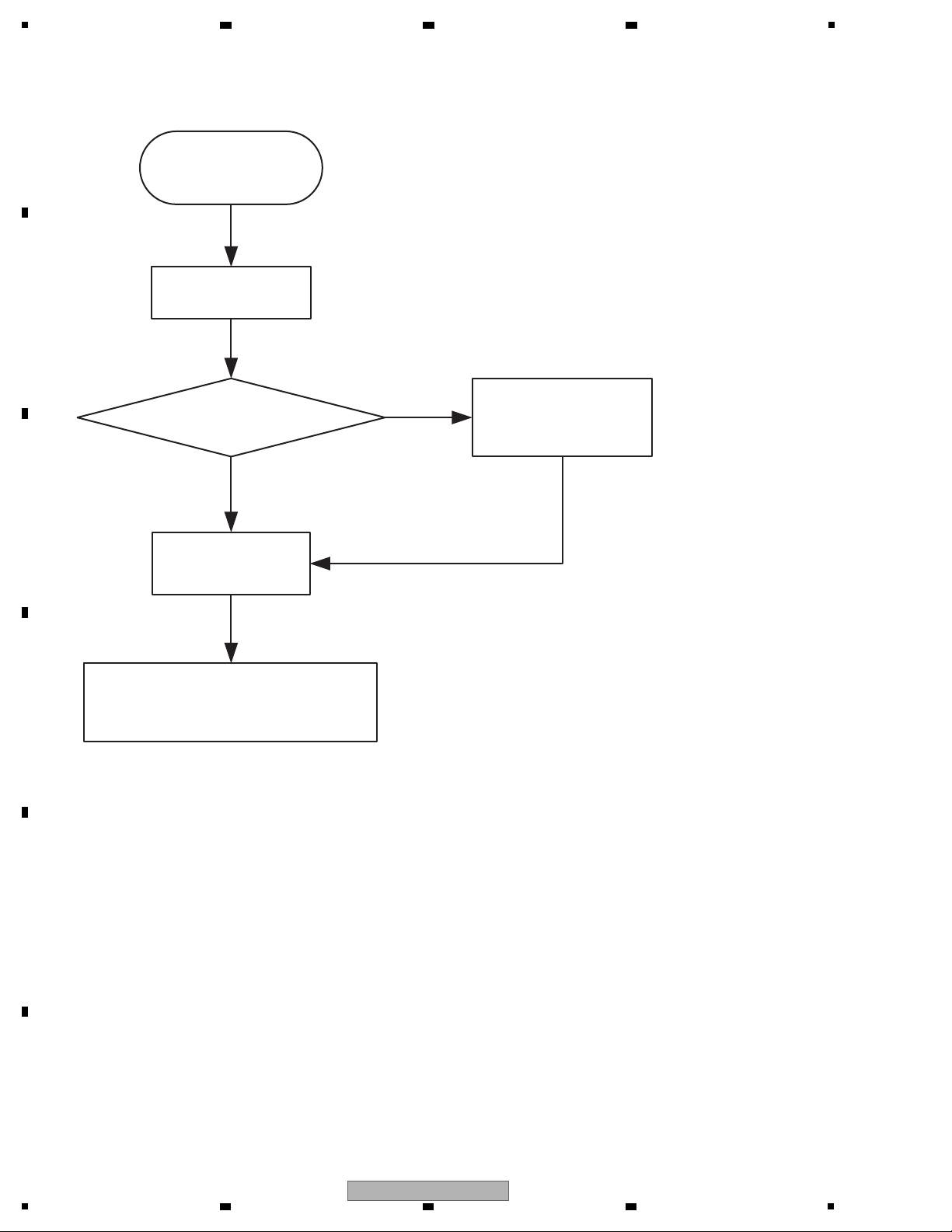
START
CPU BOOT
(TUSB3200)
Press special or updata error ?
UPDATA CODE
Yes
No
Success
CPU RUN CODE
(TUSB3200)
(KEY & FADER & SIDER & JOG dial)
start operator
5. DIAGNOSIS
5.1 BOOT SEQUENCE
A
B
2 3 4
C
D
E
F
12
1
2 3 4
DDJ-WEGO2-K
Page 13
5
[1] Power failure
CHECK Power Line
Step 1: JK501 Pin 1_5 V (waveform ), CN501 Pin 5_6.5 V (waveform ), CN501 Pin 1_-6.5 V (waveform ),
C17_3.3 V (waveform )
[2] No sound input/output from USB
CHECK Digital Audio Signal Line
Step 1: IC501 Pin 44_MCLKO (SCK)(waveform ), IC501 Pin 38 CDATI (SDO2)(waveform ),
IC501 Pin 36 CDATO (SDO1)(waveform ), IC501 Pin 35 CSYNC (LRCK)(waveform ),
IC501 Pin 34 CSCLK (BCK)(waveform )
Step 2: IC200 Pin 1 BCK (waveform ), IC200 Pin 2 SDO1 (waveform ), IC200 Pin 3 LRCK (waveform ),
IC200 Pin 16 SCK (waveform )
Step 3: IC300 Pin 16 SCK (waveform ), IC300 Pin 1 BCK (waveform ), IC300 Pin 2 SDO1 (waveform ),
IC300 Pin 3 LRCK (waveform )
[3] No sound input from MIC
CHECK Analog Audio Signal Line
Step 1: JK101 INPUT (waveform )
Step 2: MASTER OUT (waveform )
CHECK Power Line
Step 3: IC100/101/202 Pin 8_6.5 V (waveform ), IC100/101/202 Pin 4_-6.5 V (waveform )
[4] No sound output from MASTER
CHECK Power Line
Step 1: IC201/202 Pin 8_6.5 V (waveform ), IC201/202 Pin 4_-6.5 V (waveform )
CHECK Digital Audio Signal Line
Step 2: IC200 Pin 1 BCK (waveform ), IC200 Pin 2 SDO1 (waveform ), IC200 Pin 3 LRCK (waveform ),
IC200 Pin 16 SCK (waveform )
Step 3: IC200 Pin 13 MD (waveform ), IC200 Pin 14 MC (waveform ), IC200 Pin 15 ML1 (waveform )
CHECK Analog Audio Signal Line
Step 4: IC201 Pin 7/1 (waveform ), IC202 Pin 7/1 (waveform )
[5] Noise sound output from MASTER
CHECK Power Line
Step 1: IC201/202 Pin 8_6.5 V (waveform ), IC201/202 Pin 4_-6.5 V (waveform )
CHECK Digital Audio Signal Line
Step 2: IC200 Pin 1 BCK (waveform ), IC200 Pin 2 SDO1 (waveform ), IC200 Pin 3 LRCK (waveform ),
IC200 Pin 16 SCK (waveform )
Step 3: IC200 Pin 13 MD (waveform ), IC200 Pin 14 MC (waveform ), IC200 Pin 15 ML1 (waveform )
CHECK Analog Audio Signal Line
Step 4: IC201 Pin 7/1 (waveform ), IC202 Pin 7/1 (waveform )
Step 5: CN501 Pin 2/4 (waveform )
1-1
2-1
3-1
4-1
4-1
5-1
5-4
5-5 5-6 5-7
5-8
5-9
5-8
5-2 5-3
4-3 4-4 4-5
4-6
4-7 4-8 4-9
4-2
4-2
3-2
3-3 3-4
2-3
2-5
2-6
2-9
2-10 2-11 2-12
2-13
4-10 4-10
2-7 2-8
2-4
2-2
1-4
1-2 1-3
6 7 8
5.2 TROUBLESHOOTING
A
B
C
D
E
DDJ-WEGO2-K
5
6 7 8
F
13
Page 14
1
[6] No sound output from PHONES
CHECK Power Line
Step 1: IC301 Pin 8_6.5 V (waveform ), IC301 Pin 4_-6.5 V (waveform )
Step 2: IC302 Pin 2/9 3.3 V (waveform )
CHECK Digital Audio Signal Line
Step 3: IC300 Pin 1 BCK (waveform ), IC300 Pin 2 SDO1 (waveform ), IC300 Pin 3 LRCK (waveform ),
IC300 Pin 16 SCK (waveform )
Step 4: IC300 Pin 13 MD (waveform ), IC300 Pin 14 MC (waveform ), IC300 Pin 15 ML1 (waveform )
CHECK Analog Audio Signal Line
Step 5: IC302 Pin 8 (waveform )
[7] Noise sound output from PHONES
CHECK Power Line
Step 1: IC301 Pin 8_6.5 V (waveform ), IC301 Pin 4_-6.5 V (waveform )
Step 2: IC302 Pin 2/9 3.3 V (waveform )
CHECK Digital Audio Signal Line
Step 3: IC300 Pin 1 BCK (waveform ), IC300 Pin 2 SDO1 (waveform ), IC300 Pin 3 LRCK (waveform ),
IC300 Pin 16 SCK (waveform )
Step 4: IC300 Pin 13 MD (waveform ), IC300 Pin 14 MC (waveform ), IC300 Pin 15 ML1 (waveform )
CHECK Analog Audio Signal Line
Step 5: IC302 Pin 8 (waveform )
Step 6: JK301/302 Connector (waveform )
[8] Channel level indicator doesn’t light up
CHECK Power Line
Step 1: JK501 Pin 1_5 V (waveform ), CN501 Pin 5_6.5 V (waveform ), CN501 Pin 1_-6.5 V (waveform ),
C17_3.3 V (waveform ), IC607/608 Pin 16_5 V (waveform )
CHECK Digital Control Signal
Step 2: IC607/608 Pin 11 SHCP (waveform ), IC607/608 Pin 12 SHCP (waveform ),
IC607/608 Pin 13 OE (waveform )
[9] Each operation knob doesn’t work
CHECK Power Line
Step 1: VR Power Voltage 5 V (waveform )
CHECK Digital Control Signal
Step 2: IC600 Pin 68 SDA Waveform (waveform )
[10] Each operation doesn’t linked with PC
CHECK Digital Control Signal
Step 1: POWER ON SDA Waveform (waveform )
6-1
6-3
6-4 6-5 6-6
6-7
6-8
7-1 7-2
7-3
7-4 7-5 7-6
7-7
7-8
8-1 8-2 8-3
8-4 8-5
8-6 8-7
8-8
9-1
10-1
9-2
7-9
7-10
7-11
7-12
6-9
6-10
6-11
6-2
[11] Each operation doesn’t linked with iPad
CHECK Digital Control Signal
Step1: Q907i Collector Wavefrom (waveform )
Step2: IC901i Pin 1 Wavefrom (waveform ), IC901i Pin 9 Wavefrom (waveform )
Step3: IC901i Pin 2, IC901i Pin 8 Wavefrom (waveform )
11-1
11-2 11-3
11-4
A
2 3 4
B
C
D
E
F
14
1
2 3 4
DDJ-WEGO2-K
Page 15
5
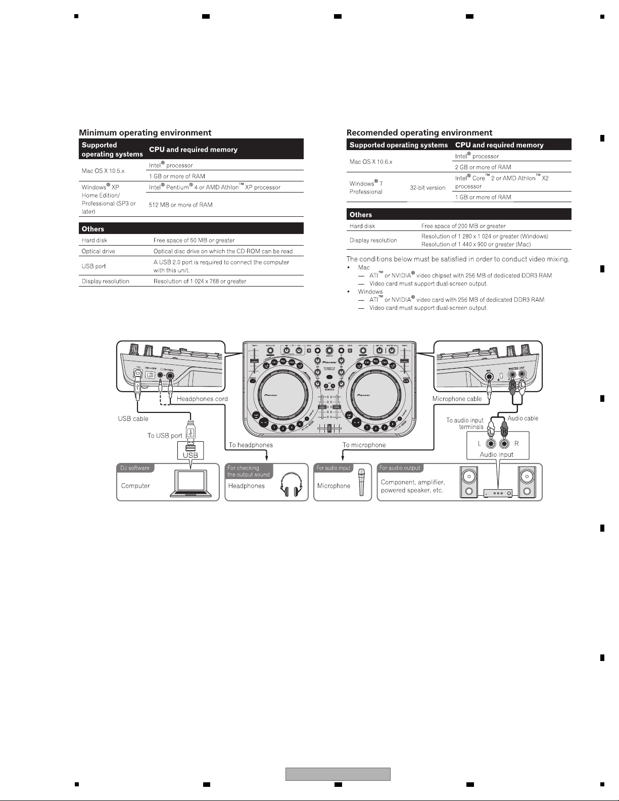
[Preparations]
Install VIRTUAL DJ LE (DJ software) on the PC. For details on installation, refer to the operation manual of the unit.
If the OS of the PC is Windows, the driver software for outputting audio from the PC must be installed beforehand.
The requirements of a PC on which VIRTUAL DJ LE can be installed are as shown below.
[Connections]
6 7 8
5.3 OPERATION CHECK WITH VIRTUAL DJ
A
B
C
D
E
F
DDJ-WEGO2-K
5
6 7 8
15
Page 16
1
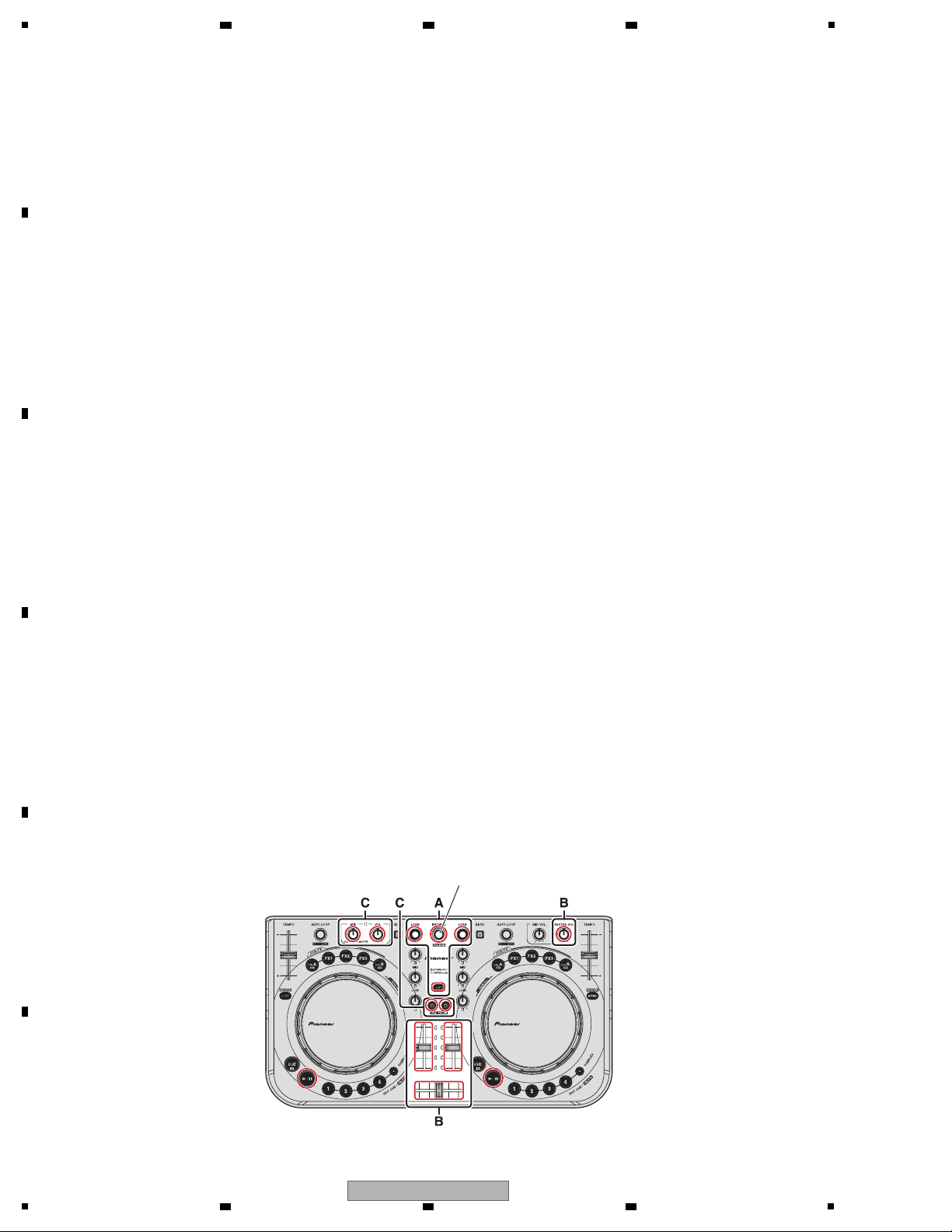
[Startup of the System]
1. Connect this unit and a PC, using a USB cable.
2. Start up the connected PC.
3. Slide the ON/OFF switch of this unit to ON to turn it on.
• Starting up the DDJ-WEGO2
[Loading and Playing a Track (A part)]
1. While holding the SHIFT button pressed, turn the rotary selector to select a folder or an item.
2. After releasing the SHIFT button, turn the rotary selector to select a track.
3. Press the LOAD button to load the selected track onto the deck.
4. Play the track by pressing the f button.
1. From the Start menu of the Windows, select All Programs, VIRTUAL DJ LE, then VirtualDJ LE (DDJ-WeGO2).
When VIRTUAL DJ LE is started for the first time, the serial number input window will be displayed.
2. After the VIRTUAL DJ LE window is displayed, click on CONFIG located in the upper left portion of the window.
If the Sound Setup tab is displayed on the Settings screen, VIRTUAL DJ LE does not recognize the DDJ-WeGO2.
Terminate VIRTUAL DJ LE, turn the unit OFF, then proceed from Step 3 of "Startup of the System" again.
3. Click on OK.
• Starting up VIRTUAL DJ LE
(Windows)
1. With the Finder, open the Applications folder then double-click on the VIRTUAL DJ LE icon.
(Enter the serial number in the same wa
y as that for Windows.)
2. After the VIRTUAL DJ LE window is displayed, click on CONFIG located in the upper left portion of the window.
If the Sound Setup tab is displayed on the Settings screen, VIRTUAL DJ LE does not recognize the DDJ-WeGO2.
Terminate VIRTUAL DJ LE, turn the unit OFF, then proceed from Step 3 of "Startup of the System" again.
3. Click on OK.
(Macintosh)
[Outputting Audio]
1. Adjust the level of the audio signal output from each deck, using the channel fader.
2. For switching the decks from which the audio signal is output, use the cross fader.
3. Adjust the audio level from the speakers, using the MASTER VOL control, in order to confirm that the audio signal is output
without a problem.
MASTER OUT OUTPUT (B part)
1. Connect the headphones to PHONES terminal.
2. Press the CUE (Headphones CUE) button of the deck which you want to monitor.
4. Adjust the audio level, using the HEADPHONE [VOL] control, in order to confirm that the audio signal is output without a
problem.
Headphones OUTPUT (C part)
Rotary selector
A
2 3 4
B
C
D
E
F
16
1
2 3 4
DDJ-WEGO2-K
Page 17

5
The Following service modes are provided for this unit:
1 FIRMWARE VERSION (MAIN UCOM) and LAST MEMORY CONFIRMATION MODE
The mode for confirmation of the firmware version, checking on a setting state of the illuminations mode and jog touch
sensitivity.
2 BUTTON INPUT AND DISPLAY FUNCTION CONFIRMATION MODE
The mode which confirms whether each button, input of the JOG dial and display are normal
3 JOG DIAL ROTATION TIME MEASUREMENT MODE
The mode which measures rotary decline time of the jog dial
4 FACTORY RESET MODE
The mode which returns the item where user setting is possible for the setting of the factory shipping state
5 iPhone/iPad CONNECTING CABLE CONFIRMATION MODE
The mode for confirmation of the iPhone/iPad connecting cable
Description of Service Modes
6 7 8
6. SERVICE MODE
A
B
C
D
E
F
DDJ-WEGO2-K
5
6 7 8
17
Page 18
A
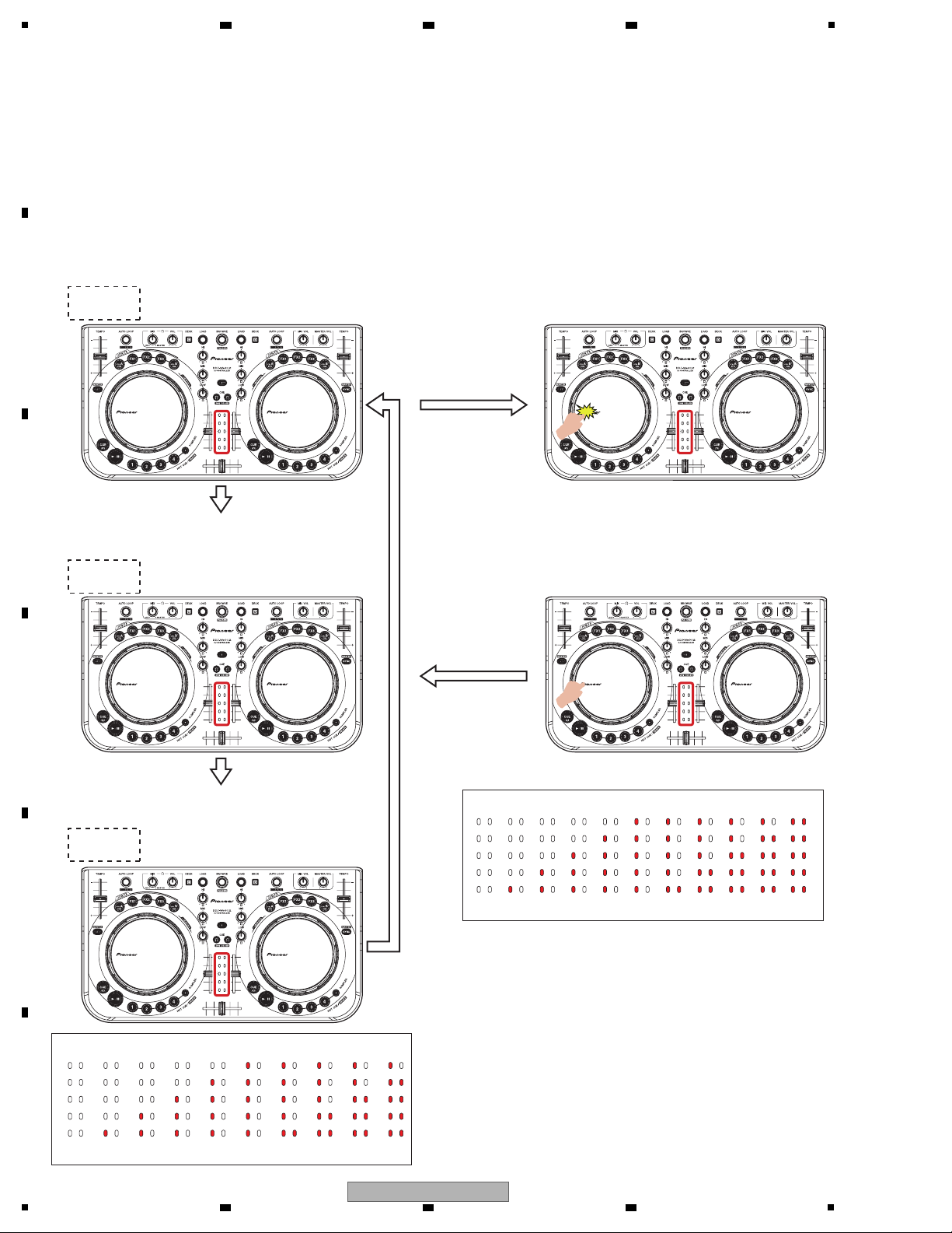
To enter this mode, while simultaneously holding the DECK C and DECK D buttons pressed, set the Power switch of the unit
to ON. (Hold the two buttons pressed until the opening display terminates.)
The version number of the firmware (MAIN UCOM) will be indicated with LED-lighting patterns that are switched every
2 seconds in integral part and decimal fraction part. In the blocks that are indicated with the red frames in the figures,
the number of lit LEDs indicates the corresponding number.
Left jog dial is
pressed.
The version display ends.
The display of the MIDI
transmission cycle of the
jog dial starts.
Confirming the Firmware Version Confirming the transmission interval (do send to
every any msec?) of sending MIDI IN for the jog
dial turning memorised in FlashRom.
1 Integral part of the version number
(LEDs on DECK C and D turn off)
2 sec
X.XX
Release your finger,
jog dial Touch ends.
The display of the MIDI
transmission cycle of the
jog dial
ends.
The version display starts.
2 sec
2
The first place of decimal fraction part of the version number
(LED on DECK C lit)
3
The second place of decimal fraction part of the version number
(LED on DECK D lit)
X.XX
X.XX
2 sec
[Numerics expressed with the number of lit LEDs]
012345678 9
[Numerics expressed with the number of lit LEDs]
3 ms 4 ms 5 ms 6 ms 7 ms 8 ms 9 ms 10 ms 11 ms 12 ms 13 ms
1
6.1
FIRMWARE VERSION (MAIN UCOM) and LAST MEMORY CONFIRMATION MODE
2 3 4
B
C
D
E
F
18
1
DDJ-WEGO2-K
2 3 4
Page 19
5
Apart from the firmware-version indication, the current settings of the user settable items (Color of the jog dial's illumination,
Sensitivity of the jog dial's touch sensor, and Illuminations mode) are indicated with other LEDs.
Confirmation of Last Memory
Mode Point Mode setting state LED display
Color of the jog dial’s
illumination
Illumination mode
Sensitivity of the jog
dial’s touch sensor
DECK A —————
While the DECK A–D buttons are lit alternately at
intervals of 2 sec., the LEDs of the jog dial will be lit in
the color of illumination corresponding to the setting
for each deck.
DECK B —————
DECK C —————
DECK D —————
[HOT CUE1] button on the left deck Sensitivity: -4 (low)
A [HOT CUE] button or the [SAMPLER] buttons will
light, corresponding to the set sensitivity.
[HOT CUE1] button on the right deck Sensitivity: +1
[HOT CUE2] button on the right deck Sensitivity: +2
[HOT CUE3] button on the right deck Sensitivity: +3
[HOT CUE4] button on the right deck
Headphone [CUE] button
Sensitivity: +4 (high)
Pulse Mode: Active
Both headphone [CUE] buttons will be lit.
Both headphone [CUE] buttons will be lit off.
Pulse Mode: Normal
[HOT CUE2] button on the left deck Sensitivity: -3
[HOT CUE3] button on the left deck Sensitivity: -2
[HOT CUE4] button on the left deck Sensitivity: -1
[SAMPLER] button on the both deck Sensitivity: 0
6 7 8
A
B
C
D
E
F
DDJ-WEGO2-K
5
6 7 8
19
Page 20

1
Confirmation of Input to Each Element and Display Function
To enter this mode, while holding the SYNC and CUE buttons on the Deck A/C side pressed, set the Power switch to ON.
(Enter this mode, when opening display is terminated.)
In this mode, you can check if pressing each of button or turning of the jog dial is properly input and indications are also
properly displayed. The indication corresponding to a pressed button is lit only while the button is held pressed.
All the button have to be off except pressed button when all the buttons are on by Browse button.
Hold the [LOAD] and [DECK D] button and power on till all LED turn on, then release.
All LED Turn On Mode:
DECK C BUTTON DECK C 1
DECK D BUTTON DECK D 2
DECK A/C AUTO LOOP ENCODER JOG LED ROTATION A1
AUTO LOOP PUSH ENCODER CTRL A 1
SYNC A/C BUTTON SYNC A/C 1
HOT CUE 1 BUTTON HOT CUE 1 1
HOT CUE 2 BUTTON HOT CUE 2 1
HOT CUE 3 BUTTON HOT CUE 3 1
HOT CUE 4 BUTTON HOT CUE 4 1
SAMPLER BUTTON SAMPLER 1
CUE BUTTON CUE 1
PLAY/PAUSE BUTTON PLAY/PAUSE 1
TEMPO SLIDER SLIDE VOLUME FADER LED A 1
JOG ROTATION DIAL JOG LED ROTATION A1
JOG TOUCH DIAL JOG LED ALL ON 1
CTRL A BUTTON CTRL A 1
FX 1 BUTTON FX 1 1
FX 2 BUTTON FX 2 1
FX 3 BUTTON FX 3 1
CTRL B BUTTON CTRL B 1
DECK B/D AUTO LOOP ENCODER JOG LED ROTATION B2
AUTO LOOP PUSH ENCODER CTRL A 2
SYNC B/D BUTTON SYNC B/D 2
HOT CUE 1 BUTTON HOT CUE 1 2
HOT CUE 2 BUTTON HOT CUE 2 2
HOT CUE 3 BUTTON HOT CUE 3 2
HOT CUE 4 BUTTON HOT CUE 4 2
SAMPLER BUTTON SAMPLER 2
SHIFT BUTTON LOOP OUT 2
CUE BUTTON CUE
2
PLAY/PAUSE BUTTON PLAY/PAUSE 2
TEMPO SLIDER SLIDE VOLUME FADER LED B 2
JOG ROTATION DIAL JOG LED ROTATION B2
JOG TOUCH DIAL JOG LED ALL ON 2
CTRL A BUTTON CTRL A 2
FX 1 BUTTON FX 1 2
FX 2 BUTTON FX 2 2
FX 3 BUTTON FX 3 2
CTRL B BUTTON CTRL B 2
Part Operation Device LED display DECK
2 3 4
6.2 BUTTON INPUT and DISPLAY FUNCTION CONFIRMATION MODE
A
B
C
D
E
F
20
1
2 3 4
DDJ-WEGO2-K
Page 21

5
MIXER LOAD A/C BUTTON FX 1 A/C 1
LOAD B/D BUTTON FX 1 B/D 2
BROWSE CONTROL ENCODER JOG LED ROTATION A/B 1/2
BROWSE PUSH ENCODER ALL LED BRIGHT -> OFF -> (Cyclic by push) 1/2
EQ HI A/C ROTARY VOLUME JOG LED ROTATION A1
EQ HI B/D ROTARY VOLUME JOG LED ROTATION B2
EQ MID A/C ROTARY VOLUME JOG LED ROTATION A1
EQ MID B/D ROTARY VOLUME JOG LED ROTATION B2
EQ LOW A/C ROTARY VOLUME JOG LED ROTATION A1
EQ LOW B/D ROTARY VOLUME JOG LED ROTATION B2
MASTER VOL ROTARY VOLUME JOG LED ROTATION A/B 1/2
HEADPHONE MIX ROTARY VOLUME JOG LED ROTATION A/B 1/2
HEADPHONE VOL ROTARY VOLUME JOG LED ROTATION A/B 1/2
HEADPHONE CUE A/C BUTTON HEADPHONE CUE A/C 1
HEADPHONE CUE B/D BUTTON HEADPHONE CUE B/D 2
FADER A/C SLIDE VOLUME FADER LED A 1
FADER B/D SLIDE VOLUME FADER LED B 2
CROSS FADER SLIDE VOLUME
FADER LED A/B 1/2
SHIFT BUTTON All LED of Level meter 1/2
[Indications by the VOL control]
The volume level is indicated in 8 steps from minimum to maximum.
Brightness will be adjusted as standard brightens. At the minimum volume, LEDs 12, 13, and 14 are lit. The lighting
LEDs shift as the volume is increased, and LEDs 3, 4, and 5 are lit at the maximum volume.
Brightness will be adjusted as standard brightens.
MIN
1
2
3
4
5
6
7
810
11
12
13
14
15
16
9
MAX
1
2
3
4
5
6
7
810
11
12
13
14
15
16
9
Part Operation Device LED display DECK
6 7 8
A
B
C
D
E
F
DDJ-WEGO2-K
5
6 7 8
21
Page 22

1
[Indications by the FADER control]
Indicate 10 steps as divided 10 between Min and Max.
All the LED off is MIN, All on is MAX on each Deck.
[Indications by the jog dial]
When touched jog dial, all LED on jog dial turn on.
In case of Cross Fader, All the LED off is MIN, All on is
MAX on each Deck.
ex) In case of left Deck
MIN MAX MIN MAX
1
2
3
4
5
6
7
810
11
12
13
14
15
16
9
LED of jog dial doesn't turn on in case of turning jog dial.
1
2
3
4
5
6
7
810
11
12
13
14
15
16
9
When jog dial is turned with touched jog dial platter, 3LED of jog dial turns.
1
2
3
4
5
6
7
810
11
12
13
14
15
16
9
A
2 3 4
B
C
D
E
F
22
1
DDJ-WEGO2-K
2 3 4
Page 23

5
This is a mode measuring jog dial rotation decline time of this unit.
When there was designation of the rotary malfunction of the jog dial from a customer; decline for a diagnosis.
The specified range is 100 ± 40 msec.
To enter this mode, while holding the LOAD and CTRL B buttons on the Deck A/C side pressed, set the Power switch to ON.
During this mode, the HeadPhone CUE LEDs on both sides are lit.
(Enter to this mode when Opening display is terminated.)
1. Jog dial Rotation Time Measurement Mode
1 Yo u spin Jog dial more than 33*7 = 231 rpm.
*1: In case of less than 231 rpm, the controller blinks all jog dial LED at 3 times.
blinking cycle: 1 sec
*2: You correspond both of clockwize and counter clockwize.
2 The controller measure T1 below.
*T1: The time that Jog rotation speed slow down from 100 rpm to 50 rpm.
2. How to Measure
2 sec
XXXms
XXXms
XXXms
2 sec
2 sec
[Numerics expressed with the number of lit LEDs]
012345678 9
6 7 8
6.3 JOG DIAL ROTATION TIME MEASUREMENT MODE
A
B
C
D
E
5
6 7 8
DDJ-WEGO2-K
F
23
Page 24

1
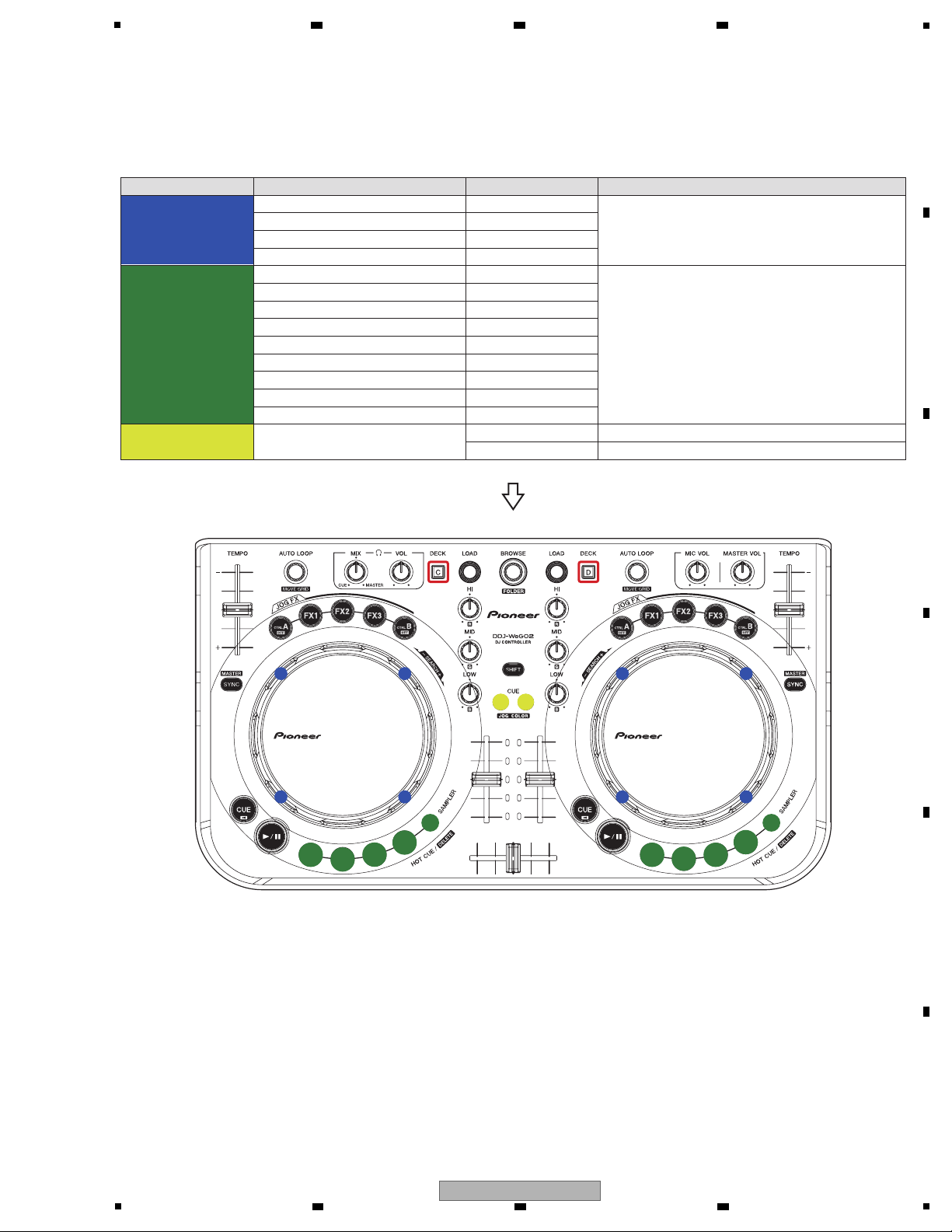
ex) If Press the FX1, JOG RGB LED will be changed as below.
To enter this mode, while simultaneously holding the Sampler and HOT CUE 1 buttons on the Deck A/C side pressed,
set the Power switch of the unit to ON. (Enter this mode when opening display terminated.)
Memorize Table 1 items when enter this mode.
JOG LED color is frosty white when the controller is launched after FACTORY RESET.
The color of the RGB LEDs of the jog dials must be set according to the color of each controller at the factory.
Press a setting button shown in the table below, according to the color of the cabinet of the controller. The colors of the
RGB LEDs of the jog dials for all decks (A/B/C/D) will be set to their standard colors (colors corresponding to the pressed
setting buttons).
The data for color change will be stored in memory immediately before the controller is turned off.
Note: If this setting is not performed, the color of the RGB LEDs of the jog dials for all the decks will be set to frosty white
when the unit is turned ON for the next time.
Ta ble 1
Ta ble 2
1. Initial Settings
2. For the color valuation of JOG RGB LED
1
Color of the jog dial’s illumination No color settings for any deck
Color Variation on Controller
Default Color (LED)
Setting Button
Black (DDJ-WEGO2-K)
Frosty white
CTRL A
Red (DDJ-WEGO2-R)
Orange
FX1
White (DDJ-WEGO2-W)
Aqua
FX2
2
Sensitivity of the jog dial’s touch sensor Sensitivity: 0
3
Jog dial’s MIDI message sending interval 3 msec
4
Illuminations mode Active
2 3 4
6.4 FACTORY RESET MODE
A
B
C
D
E
F
24
DDJ-WEGO2-K
1
2 3 4
Page 25

5
This mode is for confirmation of the iPhone/iPad connecting cable.
Use this mode in a diagnostic procedure when the problem indicated by the user is that an iOS device (iPhone, iPad, or
iPod touch) does not recognize the DDJ-WeGO2.
1 Properly connect the iPhone/iPad connecting cable to the DDJ-WeGO2.
2 Turn the DDJ-WeGO2 ON.
3 Turn the iOS device ON.
4 Connect the Lightning connector of the connecting cable to the iOS device (iPhone/iPad/iPod touch).
5 On the iOS device, select Settings, General, then About.
If "PIONEER DDJ-WeGO2" is displayed along with the version and capacity, the DDJ-WeGO2 is properly recognized.
The items that can be confirmed in this mode are shown in the table below.
Whether or not the iOS device recognizes the DDJ-WeGO2 can be checked on the iOS device.
Operation LED indication
DECK A/C
DECK B/D
CTRL A—————
Point to check
The signal from Pin 4 (ACCESSORY POWER) of the connector of the connecting
cable can be checked:
Lit: HIGH (An iOS device is connected.)
Unlit: LOW (No iOS device is connected, or the connected iOS device is not ON.)
FX 2————— The signal from Pin 15 of TUSB3200 can be checked:
Lit: LOW (Communication with the iOS)
Unlit: HIGH (Communication with the PC)
CTRL BPress the CTRL B
button.
Whether or not communication with the Apple authentication chip inside the
connecting cable is established can be checked:
Lit: Communication successful
Flashing (at intervals of 1 sec): Communication failed.
1. Before confirmation in this mode
While simultaneously holding the FX 3 and CTRL B buttons on the B/D deck pressed, turn the unit ON to enter this mode.
(After the opening display terminates, this mode is entered.)
2. How to enter the mode for Operation Check of an iPhone/iPad Connecting Cable
1 Properly connect the iPhone/iPad connecting cable to the DDJ-WeGO2.
Do not connect the Lightning connector of the connection cable to iOS device then.
2 Start the DDJ-WeGO2 in the mode for Operation Check of an iPhone/iPad Connecting Cable.
After the unit starts then enters this mode, the CTRL A and FX 2 buttons on the left deck are unlit.
3 Turn the iOS device ON.
4 Connect the Lightning connector of the connecting cable to the iOS device.
Check that the CTRL A and FX 2 buttons are lit.
5 Press the CTRL B button on the right deck, and check whether a product can communicate with the authentication
chip inside the connecting cable correctly. When communication fails, "CTRL B" button flashes.
3. How to Confirm
6 7 8
6.5 iPhone/iPad CONNECTING CABLE CONFIRMATION MODE
A
B
C
D
E
F
DDJ-WEGO2-K
5
6 7 8
25
Page 26

1
A
-K, -R: 100-DDJLE-2952
-W: 100-WG2-2952
×5
B B BC CC CA A
A
B
-K, -R: 100-DDJLE-2945
-W: 100-WG2-2945
×3
C
-K, -R: 100-DDJLE-2944
-W: 100-WG2-2944
×10
Knobs and Volumes Location
Note:
Even if the unit shown in the photos and illustrations in this manual may differ from your product, the
procedures described here are common.
-K,-R: Black
-W: White
-K,-R: White
-W: Gray
-K, R: Black
-W: White
-K, R: Black
-W: White
-K, R: White
-W: Gray
2 3 4
7. DISASSEMBLY
A
B
C
D
E
F
26
1
2 3 4
DDJ-WEGO2-K
Page 27

5
[1] Chassis Section
(1) Remove the chassis section by removing the
six screws.
(K, R: 602-PTB3010-674B)
(W: 602-PTB3010-674Z)
Screw tightening order
Disassembly
• Bottom view
1
1
1
1
1
1
1
5
6
3
4
2
1
1
3
3
4
4
2
2
Screw tightening order
[2] MASTER and IO PCB Assemblies
(1) Release the jumper wire from the two locking
cable clip.
(2) Remove the MASTER PCB Assy with plate
by removing the four screws.
(602-SL24F-099)
(3) Disconnect the one connector.
(CN604)
(4) Remove the IO PCB Assy with plate by
removing the four screws.
(602-SL24F-099)
(5) Disconnect the one flexible cable and one
connector.
(CN605A, CN501)
(6) Remove the jumper wire by removing the one
screw.
(02-SA12-377)
MASTER PCB Assy
MASTER PCB Assy
IO PCB Assy
IO PCB Assy
• Bottom view
2 2
4
4
5
5
6
4
4
2
2
1 1
CN604
CN501
CN605A
3
6 7 8
A
B
C
D
E
5
DDJ-WEGO2-K
6 7 8
F
27
Page 28

1
[3] WHEEL (L) and (R) PCB Assemblies
(1) Remove the two wheel tooths by removing
the two screws and four washers.
(602-STR885-354)
(2) Remove the two washers and two E rings.
(3) Disconnect the two flexible cables.
(CN01A, CN02A)
(4) Remove the two Wheel Assemblies.
(5) Remove the WHEEL (L) and (R) PCB
Assemblies by removing the six screws.
(602-SL24F-099)
Wheel tooth Wheel tooth
Wheel Assy Wheel Assy
WHEEL (L) PCB Assy WHEEL (R) PCB Assy
• Bottom view
• Bottom view
1
2
5
5
5
5
5
5
2
1
4 4
CN02A CN01A
3
3
A
2 3 4
B
C
D
E
F
28
1
DDJ-WEGO2-K
2 3 4
Page 29

5
[4] CONTROL PCB Assy
(1) Remove the all knobs.
Note:
When you remove CONTROL PCB Assy, it is not necessary to remove a Wheel section.
Screw tightening order
The other screws are random order.
1
×18
CONTROL PCB Assy
1
2
3
4
5
6
7
8
9
10
11
(2) Disconnect the two flexible cables.
(CN01A, CN02A)
(3) Remove the two jumper wires by removing
the two solders.
(4) Remove the CONTROL PCB Assy by
removing the 39 screws.
(602-SL24F-099)
CONTROL PCB Assy
• Bottom view
4
×39
CN02A CN01A
2
3
3
2
6 7 8
A
B
C
D
E
F
DDJ-WEGO2-K
5
6 7 8
29
Page 30

1
The Application Position of Adhesive and Grease
Grease
(GEM1096)
Adhesive
(GYL1001)
Adhesive
(GYL1001)
Adhesive
(GYL1005)
Grease
(GEM1096)
Grease
(GEM1096)
• Bottom view
• Bottom view
Wheel Assy
MASTER PCB Assy
Sponge Sponge
IO PCB Assy
IO PCB Assy
Cushion Cushion Cushion
Cushion
Chassis Assy
A
2 3 4
B
C
D
E
F
30
DDJ-WEGO2-K
1
2 3 4
Page 31

5
After repairing, be sure to check the version of the firmware, and if it is not the latest one, update to the latest version.
Perform the each item when the following parts are replaced.
• IC and PCB Assy storing firmware and user settings
IC600 (CONTROL IC), IC618 (MIDI IC),
CONTROL PCB Assy
• Confirmation of the version of the firmware
• Updating to the latest version of the firmware
• Factory reset
• Be changed user setting to condition before the repair
(when be possible)
• Wheel Assy • Confirmation of the specified value by the mode which
measures rotary decline time of the jog dial
1 Hold the JOG COLOR CUE button and Power switch at the same time till all Channel level indicator turn on.
2 Click the Updater Program software, the information with
PC.
3 Click "Start" to update procedure, the information with PC.
4 After upgrading and finishing automatically, the
information with PC, Click "OK", finish the Firmware
update.
Procedures
Download the latest Java from the following pages, and install it in a PC for update.
http://www.java.com/ja/
Update program software name: DDJ-WeGO2_V1xx.jar
And disconnect the iPhone/iPad connection cable from the product.
Preparations
* When update fails, all level indicators blink when a
power is turned on.
In that case, please update it again.
6 7 8
8. EACH SETTING AND ADJUSTMENT
8.1 NECESSARY ITEMS TO BE NOTED
8.2 UPDATING OF THE FIRMWARE
A
B
C
D
E
5
6 7 8
DDJ-WEGO2-K
F
31
Page 32

1
Item for Which User's
Setting is Available
Setting Value (The factory default
settings are indicated in bold.)
Part Name
Content to be
Stored
Color of the jog dial’s illumination
This unit is provided with user settable items, as shown below.
Although no serious operational problems occur even if data for such user settable items are cleared during repair, it is
recommended that you take note of those settings before starting repair.
Use the Check Sheet shown below, to which you can transcribe the settings.
For details on how to confirm the settings, see "6.1 FIRMWARE VERSION (MAIN UCOM) and LAST MEMORY
CONFIRMATION MODE."
For details on the setting methods, refer to "Changing the color of the jog dial's illumination," "Adjusting the jog dial's MIDI
message sending interval," and "Adjusting the sensitivity of the jog dial's touch sensor" in the operation instructions.
Frosty white (DDJ-WEGO2-K)
Aqua (DDJ-WEGO2-W)
Orange (DDJ-WEGO2-R)
Other colors to pre-set
Red , Yellow , Green , Blue ,
Emerald green , Violet
Free setting
EQ (HI, MID, LOW) Control R G B with a knob,
and can set each color freely.
Control IC [NSP]
(IC600: CONTROL PCB Assy)
Setting coller
Illuminations mode
Pulse Mode Active / Normal
Setting mode
Sensitivity of the jog dial’s touch sensor
-4 (Low), -3, -2, -1, 0, +1, +2, +3, +4 (High)
Setting value
Jog dial’s MIDI message sending
interval
3ms, 4ms, 5ms, 6ms, 7ms, 8ms, 9ms,
10ms, 11ms, 12ms, 13ms
Setting value
Sheet for confirmation of the user settings
• Color of the jog dial’s illumination
-4
(Low)
-3
3 ms
4 ms 5 ms 6 ms 7 ms 8 ms 9 ms 10 ms 11 ms 12 ms 13 ms
-2 -1 0 +1 +2 +3
+4
(High)
• Illuminations mode
• Sensitivity of the jog dial’s touch sensor
• Jog dial’s MIDI message sending interval
Active
Pulse Mode
Normal
Blue
Original color Pre-set color
Frosty
white
Orange
Emerald
green
VioletRed Yellow GreenAqua
Others
2 3 4
8.3 ITEMS FOR WHICH USER SETTINGS ARE AVAILABLE
A
B
C
D
E
F
32
DDJ-WEGO2-K
1
2 3 4
Page 33

5
6 7 8
A
B
C
D
E
F
DDJ-WEGO2-K
5
6 7 8
33
Page 34

1
NOTES: - Parts marked by “NSP” are generally unavailable because they are not in our Master Spare Parts List.
-
The > mark found on some component parts indicates the importance of the safety factor of the part.
Therefore, when replacing, be sure to use parts of identical designation.
-
Screws adjacent to b mark on product are used for disassembly.
-
For the applying amount of lubricants or glue, follow the instructions in this manual.
(In the case of no amount instructions, apply as you think it appropriate.)
or
2 3 4
9. EXPLODED VIEWS AND PARTS LIST
A
9.1 PACKING SECTION
B
C
D
E
F
34
1
2 3 4
DDJ-WEGO2-K
Page 35

5
(1) PACKING SECTION PARTS LIST
Mark No. Description Part No.
1 USB Cable (L = 1500 mm) 408-SUB-132
2 iPhone/iPad Connection Cable 408-WG2-129
(Lightning)
3 iPhone/iPad stand See Contrast table (2)
4 Stand fixing screws See Contrast table (2)
6 7 8
No. Description Part No.
Mark
8 Handle 100-DDJLE-3012
9 Handle Base 100-DDJLE-3013
10 Gift Box See Contrast table (2)
11 Soft Bag 509-DDJLE-318
12 Soft Bag For Support 509-WG2-327
A
5 VIRTUAL DJ LE software/
• • • • • (To Be Determined)
driver software/
operating instructions CD-ROM
6 Polyfoam L 506-WG2-658L
7 Polyfoam R 506-WG2-658R
13 Read Before Use (Important)/ See Contrast table (2)
Quick Start Guide
14 Read Before Use (Important)/ See Contrast table (2)
Quick Start Guide
15 Read Before Use (Important)/ See Contrast table (2)
Quick Start Guide
(2) CONTRAST TABLE
DDJ-WEGO2-K/XE5, XE25, /XECN5, DDJ-WEGO2-R/XE5, XE25, XECN5, DDJ-WEGO2-W/XE5, XE25 and XECN5 are
constructed the same except for the following:
Mark No. Symbol and Description
3 iPhone/iPad stand 701-WG2K-5403 701-WG2K-5403 701-WG2R-5403 701-WG2R-5403 701-WG2-5403 701-WG2-5403
4 Stand fixing screws
10 Gift Box 507-WG2KA-3447B 507-WG2KB-3447A 507-WG2RA-3447B 507-WG2RB-3447A 507-WG2WA-3447B 507-WG2WB-3447A
13 Read Before Use (Important)/
Quick Start Guide
(En, Fe, De, It, Nl)
14 Read Before Use (Important)/
Quick Start Guide
(Es, Pt, Ru, Ko, Ja)
15 Read Before Use (Important)/
Quick Start Guide (Zhcn)
DDJ-WEGO2-K
/XE5, XE25
602-SWISO415-745B 602-SWISO415-745B 602-SWISO415-745B 602-SWISO415-745B 602-SWISO415-745Z 602-SWISO415-745Z
502-WG2A-3328A Not used 502-WG2A-3328A Not used 502-WG2A-3328A Not used
502-WG2A-3329A Not used 502-WG2A-3329A Not used 502-WG2A-3329A Not used
Not used 502-WG2B-3330 Not used 502-WG2B-3330 Not used 502-WG2B-3330
DDJ-WEGO2-K
/XECN5
DDJ-WEGO2-R
/XE5, XE25
DDJ-WEGO2-R
/XECN5
DDJ-WEGO2-W
/XE5, XE25
DDJ-WEGO2-W
/XECN5
B
C
D
E
F
DDJ-WEGO2-K
5
6 7 8
35
Page 36

1
A
C
B
E
D
SN label
(NSP)
Decorating sheet
(NSP)
Wheel ring Assy
(NSP)
Spring
(NSP)
Screw
(NSP)
-R, W model
only
-R, W model
only
-R, W model
only
-R, W model
only
Cloth tape
(NSP)
Cloth tape
(NSP)
Bar-code
(NSP)
x10
: Accessories of VR
(NSP)
Accessory
Accessory
9.2 EXTERIOR SECTION
A
2 3 4
B
C
D
E
F
36
DDJ-WEGO2-K
1
2 3 4
Page 37

5
(1) EXTERIOR SECTION PARTS LIST
Mark No. Description Part No.
1 CONTROL PCB Assy 704-WG2-A604
2 IO PCB Assy 704-WG2-A607
3 MASTER PCB Assy 704-WG2-A608
4 WHEEL (R) PCB Assy 704-WG2-A609
5 WHEEL (L) PCB Assy 704-WG2-A610
6 7 8
No. Description Part No.
Mark
46 Anti-Dazzling Bag See Contrast table (2)
47 Clip 603-PROS2-256A
48 Foot Pad 604-DDJLE-604
49 Stand fixing screws See Contrast table (2)
50 1..iPhone/iPad stand See Contrast table (2)
A
6 1P Lead Wire 406-DDJLE-1227
7 11P 1.0 FFC Cable 406-WG2-1261
8 3P Ground Wire 406-WG2-1263
9 1..Wheel Assy See Contrast table (2)
10 2..Wheel Frame See Contrast table (2)
11 2..Screw See Contrast table (2)
12 Chassis Assy See Contrast table (2)
13 Spacer 612-DDJLE-447
14 Sponge 612-PDJ22-428
15 Protected Cover See Contrast table (2)
16 Plug See Contrast table (2)
17 Fixed Base Assy 703-DDJLE-1376
18 Fixed Plate Assy 703-WG2-1391
19 Wheel Tooth 100-DDJLE-2943
20 Jog Tuning Knob See Contrast table (2)
21 Rotate Knob See Contrast table (2)
22 FX Knob See Contrast table (2)
23 Hot Cue Knob See Contrast table (2)
24 Playcue Knob See Contrast table (2)
25 Square Knob 100-DDJLE-2949
26 Square Knob 100-DDJLEA-2949
27 Circular Knob See Contrast table (2)
28 Circular Knob See Contrast table (2)
29 Circular Knob See Contrast table (2)
30 Elliptic Knob See Contrast table (2)
51 2..Pad See Contrast table (2)
52 2..Foot Pad 604-WG2-642
53 Cushion 612-DDJLE-441
54 Cushion 612-202-220
55 Pulley Washer 606-F200-003
56 E Ring 606-DJ3000-105
57 Washer 606-MCD810-204
58 Washer 606-MCD810-205
59 Washer 606-DDJLE-260
60 Screw 602-M100-031
61 Screw 602-SL24F-099
62 Screw 602-HP1010K-181
63 Screw 602-STR885-354
64 Screw 602-LC58FA-371
65 Screw 602-SA12-377
66 Screw 602-SA12-414
67 Screw See Contrast table (2)
68 Screw 602-STS2003-677
69 Screw 602-ST306-728B
B
C
D
31 Push Knob See Contrast table (2)
32 LED Lens 100-DDJLE-2953
33 Left Knob See Contrast table (2)
34 Right Knob See Contrast table (2)
35 Base See Contrast table (2)
36 Little Frame Plastic See Contrast table (2)
37 Locking Cable Clip 300-HM510B-224
38 Locking Cable Clip 300-HM510B-224A
39 VR Fixed Plate 300-DDJLE-2029A
40 R Output Fixed Plate 300-DDJLE-2031
41 L Output Fixed Plate 300-WG2-2099
42 Ground Plate 300-WG2-2100
43 Separate Sheet 501-WG2-2586
44 Locking Cable Clip 504-HV3500K-033
45 Anti-Dazzling Bag See Contrast table (2)
DDJ-WEGO2-K
5
6 7 8
E
F
37
Page 38

1
2 3 4
(2) CONTRAST TABLE
DDJ-WEGO2-K/XE5, XE25, /XECN5, DDJ-WEGO2-R/XE5, XE25, XECN5, DDJ-WEGO2-W/XE5, XE25 and XECN5 are
constructed the same except for the following:
A
Mark No. Symbol and Description
9 Wheel Assy 701-WG2K-5349 701-WG2K-5349 701-WG2R-5349 701-WG2R-5349 701-WG2-5349 701-WG2-5349
10 Wheel Frame 100-DDJLE-2942S 100-DDJLE-2942S 100-DDJLE-2942S 100-DDJLE-2942S 100-WG2-2942 100-WG2-2942
11 Screw 602-PTB2006-733B 602-PTB2006-733B 602-PTB2006-733B 602-PTB2006-733B 602-PROS2-363 602-PROS2-363
12 Chassis Assy 701-WG2K-5223 701-WG2K-5223 701-WG2R-5223 701-WG2R-5223 701-WG2-5223 701-WG2-5223
15 Protected Cover 604-WG2K-624 604-WG2K-624 604-WG2R-624 604-WG2R-624 604-WG2-624 604-WG2-624
16 Plug 604-DDJLEB-606 604-DDJLEB-606 604-WG2R-606 604-WG2R-606 604-WG2-606 604-WG2-606
20 Jog Tuning Knob 100-DDJLE-2944 100-DDJLE-2944 100-DDJLE-2944 100-DDJLE-2944 100-WG2-2944 100-WG2-2944
21 Rotate Knob 100-DDJLE-2945 100-DDJLE-2945 100-DDJLE-2945 100-DDJLE-2945 100-WG2-2945 100-WG2-2945
22 FX Knob 100-WG2K-2946 100-WG2K-2946 100-WG2K-2946 100-WG2K-2946 100-WG2-2946 100-WG2-2946
23 Hot Cue Knob 100-DDJLE-2947 100-DDJLE-2947 100-DDJLE-2947 100-DDJLE-2947 100-WG2-2947 100-WG2-2947
DDJ-WEGO2-K
/XE5, XE25
DDJ-WEGO2-K
/XECN5
DDJ-WEGO2-R
/XE5, XE25
DDJ-WEGO2-R
/XECN5
DDJ-WEGO2-W
/XE5, XE25
DDJ-WEGO2-W
/XECN5
B
C
24 Playcue Knob 100-WG2K-2948 100-WG2K-2948 100-WG2K-2948 100-WG2K-2948 100-DDJLE-2948 100-DDJLE-2948
27 Circular Knob 100-DDJLE-2950 100-DDJLE-2950 100-DDJLE-2950 100-DDJLE-2950 100-WG2-2950 100-WG2-2950
28 Circular Knob 100-DDJLEA-2950 100-DDJLEA-2950 100-DDJLEA-2950 100-DDJLEA-2950 100-WG2A-2950 100-WG2A-2950
29 Circular Knob 100-DDJLEB-2950 100-DDJLEB-2950 100-DDJLEB-2950 100-DDJLEB-2950 100-WG2B-2950S 100-WG2B-2950S
30 Elliptic Knob 100-DDJLE-2951 100-DDJLE-2951 100-DDJLE-2951 100-DDJLE-2951 100-WG2-2951 100-WG2-2951
31 Push Knob 100-DDJLE-2952 100-DDJLE-2952 100-DDJLE-2952 100-DDJLE-2952 100-WG2-2952 100-WG2-2952
33 Left Knob 100-DDJLE-2954 100-DDJLE-2954 100-DDJLE-2954 100-DDJLE-2954 100-WG2-2954 100-WG2-2954
34 Right Knob 100-DDJLE-2955 100-DDJLE-2955 100-DDJLE-2955 100-DDJLE-2955 100-WG2-2955 100-WG2-2955
35 Base 100-WG2KA-3064A 100-WG2KB-3064 100-WG2RA-3064A 100-WG2RB-3064 100-WG2WA-3064A 100-WG2WB-3064
36 Little Frame Plastic 100-WG2K-3065 100-WG2K-3065 100-WG2K-3065 100-WG2K-3065 100-WG2-3065 100-WG2-3065
45 Anti-Dazzling Bag Not used Not used 505-80DSP-239 505-80DSP-239 505-80DSP-239 505-80DSP-239
46 Anti-Dazzling Bag Not used Not used 505-80DSP-240 505-80DSP-240 505-80DSP-240 505-80DSP-240
49 Stand fixing screws
50 iPhone/iPad stand 701-WG2K-5403 701-WG2K-5403 701-WG2R-5403 701-WG2R-5403 701-WG2-5403 701-WG2-5403
51 Pad 604-WG2K-625 604-WG2K-625 604-WG2R-625 604-WG2R-625 604-WG2-625 604-WG2-625
67 Screw 602-PTB3010-674B 602-PTB3010-674B 602-PTB3010-674B 602-PTB3010-674B 602-PTB3010-674Z 602-PTB3010-674Z
602-SWISO415-745B 602-SWISO415-745B 602-SWISO415-745B 602-SWISO415-745B 602-SWISO415-745Z 602-SWISO415-745Z
D
E
F
38
1
2 3 4
DDJ-WEGO2-K
Page 39

5
6 7 8
A
B
C
D
E
F
DDJ-WEGO2-K
5
6 7 8
39
Page 40

1
/UR ST
C605
0.1
C601
0.1
123
4
C
C
R60
10K
SWI M
1
2
3
4
5
6
7
8
9
10
11
12
13
14
15
16
17
18
19
20
VDD
SWI M
GND
/RST
C606
0.01
C6070.01
C6080.01
AD15
C6090.01
+
C604
0.68u(T)
AD12
AD13
C681
1/16
C678
1/16
R677
51K
R613
20K
R611
1K
R612
2.4K
C679
0.1
VCC
1
RA5
2
RA4
3
RA3
4
RC5
5
RC4
6
RC37RC2
8
RC1
9
RC0
10
RA2
11
RA1
12
RA0
13
GND
14
IC611
PIC16F 616
C677
1/16
C674
1/16
R672
51K
R673
20K
R674
1K
R675
2.4K
C675
0.1
VCC
1
RA5
2
RA4
3
RA3
4
RC5
5
RC4
6
RC3
7
RC2
8
RC1
9
RC0
10
RA2
11
RA1
12
RA0
13
GND
14
IC610
PIC16F 616
C655
0.01
HP_MI X
C657
0.01
C656
0.01
HP_VOL
MAI N_VOL
AD14'
0Y
1
2Y
2
YCOM
3
3Y
4
1Y
5
INH
6
VEE
7
GND8B
9
A
10
3X
11
0X
12
XCOM
13
1X
14
2X
15
VCC
16
IC609
BU4052
C668
0.1
C660
0.01
C662
0.01
C661
0.01
A_HI
A_MI D
A_L OW
C664 0.01
B_HI
C666
0.01
C665
0.01
B_MI D
B_L OW
AD10'
AD9'
A
B
31
24
75
68
VR620
10K BX2
C672 0.01
TEMP 2
AD5'
3 1
24
75
68
VR619
10K BX2
C670
0.01
TEMP 1
AD15'
L601
100uH
R614
1K
ZD602
EDZ CTE61 6.8B
CHASSI S2
C680
1000P
L602
100uH
R676
1K
ZD601
EDZ CTE61 6.8B
C676
1000P
AD6'
AD8'
31
2
VR601
20K B
31
2
VR602
20K B
31
2 VR603
20K B
31
2 VR618
20K B
CROSSF ADERC669
0.01
AD7'
R1A
R1B
R2A
R2B
R3A
R3B
Q11Q22Q33Q44Q55Q66Q77GND
8
D SO
9MR10
SHC P
11
STC P
12OE13DS14Q015
VCC
16
IC602
74595
C636
0.1
Q11Q22Q33Q44Q55Q6
6Q77
GND
8
DSO
9MR10
SHC P
11
STC P
12OE13DS14Q015
VCC
16
IC601
74595
R801
3K
C635
0.1
MOSI
STC P1
SHC P
STC P1
SHCP
D801
R802
3K
Q11Q22Q33Q44Q55Q66Q77GND
8
DSO
9MR10
SHC P
11
STC P
12OE13
DS
14Q015
VCC
16
IC603
74595
R860
4.7K
R859
4.7K
R858
4.7K
R857
4.7K
R856
4.7K
C637
0.1
D856
D857
D858
D859
D860
STC P1
SHC P
D855
R855
4.7K
KS1
KS2
KR2
KR3
KR7
KR1
SW615
CUE- B
SW609
JFX3- A
SW610
SYNC- A
D604
1SS355
D605
1SS355
D606
1SS355
D607
1SS355
SW604
HOTCUE2- A
SW605
HOTCUE1- A
SW616
PLAY- B
SW617
HOTCUE1-
D611
1SS355
D612
1SS355
D613
1SS355
D614
1SS355
SW611
JFXA- A
SW612
JFX1- A
SW606
PLAY- A
SW607
CUE- A
D618
1SS355
D619
1SS
D620
1SS355
D621
1SS
SW618
HOTCUE2-
SW619
HOTCUE3-
SW613
JFX2- A
SW614
DECK -A
SW620
HOTCUE4-
SW621
SAMP LER-
D601
1SS355
D602
1SS355
D603
1SS355
SW601
SAMP LER- A
D608
1SS355
D609
1SS355
D610
1SS355
SW608
JFXB- A
SW602
HOTCUE4- A
SW603
HOTCUE3- A
D615
1SS
D616
1SS
D617
1SS
R862
3.3K
R803
3K
D803
R804
3K
R863
3.3K
R805
3K
D805
R806
3K
R864
3.3K
R807
3K
D807
R808
3K
R865
3.3K
R809
3K
D809
R810
3K
R866
3.3K
R811
3K
D811
R812
3K
R867
3.3K
R813
3K
D813
R814
3K
R868
3.3K
Q801
C114EK A
Q803
C114EK A
Q805
C114EK A
Q807
C114EK A
Q809
C114EK A
Q811
C114EK A
Q813
C114EK A
R817
3K
D817
R818
3K
R869
3.3K
R819
3K
D819
R820
3K
R870
3.3K
R821
3K
D821
R822
3K
R871
3.3K
Q817
C114EK A
Q819
C114EK A
Q821
C114EK A
Q11Q22Q33Q44Q55Q66Q77GND
8
DSO
9MR10
SHC P
11
STC P
12OE13DS14Q015
VCC
16
IC608
74595
C642
0.1
Q11Q22Q33Q44Q5
5Q66Q77
GND
8
DSO
9MR10
SHC P
11
STC P
12OE13DS14Q015
VCC
16
IC607
74595
C641
0.1
STC P1
SHC P
STC P1
SHC P
R854
4.7K
R853
4.7K
R852
4.7K
R851
4.7K
D851
D852
D853
D854
R861
1.8K
R824
1.8K
R823
1.8K
R816
1.8K
D816
D823
D824
D861
D815
R815
560
R849
1.8K
D849
A_DECK
A_Sample
AD13'
AD12'
KR4
KR5
KR6
AD14
AD2'
Q11Q22Q33Q44Q55Q66Q77GND
8
D SO
9
MR
10
SHCP
11
STC P
12OE13DS14Q015
VCC
16
IC605
74595
C639
0.1
Q11Q22Q33Q44Q55Q66Q77GND
8
DSO
9MR10
SHC P
11
STCP
12OE13DS14Q015
VCC
16
IC604
74595
R825
3K
C638
0.1
MOSI
STC P2
SHC P
/OE
STC P2
SHC P
D831
R826
3K
Q11Q22Q33Q44Q55Q66Q77GND
8
DSO
9MR10
SHC P
11
STCP
12OE13DS14Q015
VCC
16
IC606
74595
C640
0.1
STC P2
SHC P
R872
3.3K
R827
3K
D829
R828
3K
R873
3.3K
R829
3K
D827
R830
3K
R874
3.3K
R831
3K
D825
R832
3K
R875
3.3K
R833
3K
D840
R834
3K
R876
3.3K
R835
3K
D835
R836
3K
R877
3.3K
R837
3K
D833
R838
3K
R878
3.3K
Q825
C114EK A
Q827
C114EK A
Q829
C114EK A
Q831
C114EK A
Q833
C114EK A
Q835
C114EK A
Q837
C114EK A
R841
3K
D848
R842
3K
R879
3.3K
R843
3K
D847
R844
3K
R880
3.3K
R845
3K
D845
R846
3K
R881
3.3K
Q841
C114EK A
Q843
C114EK A
Q845
C114EK A
R848
1.8K
R847
1.8K
R840
1.8K
D837
D843
D841
D839
R839
560
A_DECK
A_Sample
WHEEL 1
WHEEL 2
AG
AD15
R658
1K
R659
1K
R660
1K
AD14
AD13
R662
1K
AD9
AD8
R664
1K
AD0
R6711K AD5
R666
1K
R667
1K
AD1
AD2
KS6
AD7
AD6
AD12
AD10
R663
1K
R694
1K
R695
1K
R696
1K
R697
1K
AD15'
AD14'
AD13'
AD9'
AD8'
AD0'
AD5'
AD1'
AD2'
AD7'
AD6'
AD12'
AD10'
/OE
/OE
/OE
/OE
/OE
/OE
/OE
R952
470K
R953
470K
R954
470K
R956
470K
R957
470K
R958
470K
R959
470K
R960
470K
R961
470K
R962
470K
R963
470K
R965
470K
R968
51K
C693
2.2/50
R698
10K
CS
1
SO
2
WP
3
GND4SI
5
SCK
6
HOL D
7
VCC
8
IC618
EN25F 10-100GI P
R885
300
R886
300
ZD603
TF Z 3.3B
R887
82
SO
SI
W3B
W3A
R885A
750
R886A
750
C513
0.1
R888
0
NC
1
A
2
GND
3
Y
4
VCC
5
IC502
SN74L VC1G17
R889
300
R890
750
R891
10K
D658
SMAJ6.0A
R699
1K
EMI
D654
EDZ CTE61 6.8B
D655
EDZ CTE61 6.8B
D656
EDZ CTE61 6.8B
D657
EDZ CTE61 6.8B
D660
EDZ CTE61 6.8B
CHASSI S1
C694
1u/16
SC
SC
C682 0.1
W4B
W4A
/CS
/CS
C673 0.01
R964
470K
C671 0.01
R955
470K
CHASSI S1
CHASSI S2
C645
0.1
C646
0.1
FGNDFGND
31
2VR609
20K B
31
2VR610
20K B
31
2VR611
20K B
31
2 VR613
20K B
31
2 VR614
20K B
31
2 VR615
20K B
L603
D663
RSB6.8S
D665
RSB6.8S
D664
RSB6.8S
D662
RSB6.8S
D666
SMAJ6.0A
D667
SMAJ6.0A
L604
100uH
C696
0.1
R700
1K
R688
1K
CHASSI S
CHASSI S1
R689
1K
R687
1K
R678
1K
R679
1K
R680
1K
L606
10uH
L607
33uH
D669
RSB6.8S(NC)
D668
RSB6.8S(NC)
L613
33uH
L615
33uH
R621
2.2K
R620
2.2K
R630
6.2K
R631
6.2K
R632
6.2K
R633
6.2K
R634
6.2K
R635
6.2K
R636
6.2K
L619
33uH
A
8-5
8-5
8-68-78-8 8-8 8-7 8-6
2 3 4
10. SCHEMATIC DIAGRAM
10.1 CONTROL PCB ASSY
A
B
C
D
E
F
40
1
DDJ-WEGO2-K
2 3 4
Page 41

TO F RONT PCB WN701
C613
0.1
C628
47/35(TL )
C626
0.1
AD0
AD8
AD9
AD10
AD7
AD2
AD1
/UR ST
C605
0.1
C601
0.1
123
4
CN600(NC)
CON4
B
A
R601
10K
SWI M
C627
0.1
AGND
NRST
1
OSCI N/P A1
2
OSCOUT/P A2
3
VSSI O_1
4
VSS
5
VCAP
6
VDD
7
VDDI O_1
8
(TI M3_CH1)TI M2_CH3/P A3
9
UART1_RX/(HS)P A4
10
UART1_TX/(HS)P A5
11
UART1_CK /(HS)PA6
12
(HS)PH0
13
(HS)PH1
14
PH2
15
PH3
16
AI N15/P F7
17
AI N14/P F6
18
AI N13/P F5
19
AI N12/P F4
20
AIN11/PF 3
21
VREF+22VDDA23VSSA24VREF-25AIN10/PF 026AIN7/PB727AIN6/PB628(I2C _SDA )AIN5/PB 529(I2C _SCL )A IN4/PB430(TI M1_E T R)A IN3/PB331(TIM1_CH3N)AIN2/PB2
32
(TI M1_C H2N )AI N1/PB 133(TI M1_C H1N )A IN0/PB 034TIM1_ET R/PH435TIM1_CH 3N/PH5
3
6
TIM1_CH 2N/PH637TI M1_CH 1N /PH738A IN8/PE 7
39
AIN9/PE6
40
PE5/SPI _NSS
41
PC0/ADC_ETR
42
PC1(HS)/TI M1_CH1
43
PC2(HS)/TI M1_CH2
44
PC3(HS)/TI M1_CH3
45
PC4(HS)/TI M1_CH4
46
PC5(HS)/SP I_SCK
47
VSSI O_2
48
VDDI O_2
49
PC6(HS)/SP I_MOSI
50
PC7(HS)/SP I_MI SO
51
PG0/CAN_TX
52
PG1/CAN_RX
53
PG2
54
PG3
55
PG4
56
PI0
57
PI1
58
PI2
59
PI3
60
PI4
61
PI5
62
PG5
63
PG6
64
PG7
65
PE4
66
PE3/T IM1_B KI N67PE2(T )/I2C_SD A
68
PE1(T )/I2C _SCL
69
PE0 (HS)/C LK_CCO
70
PI671PI7
72
PD0(HS)/TIM3_CH2(TIM1_BK IN)(CLK_CCO)
73
PD1(H S)/SWIM
74
PD2(HS)/TIM3_CH1(TIM2_CH3)
75
PD3(H S)/TIM 2_CH 2(AD C_E TR)
76
PD4(HS)/TIM2_CH1(BEEP)
77
PD5/U AR T3_TX
78
PD6/UART3_RX
79
PD7/TLI(TIM1_C H4)
80
IC600
STM8S207MB
VDD
SWI M
GND
/RST
C625
0.01
C615
0.01
C6070.01
C6080.01
C6090.01
C624
0.01
C623
0.01
C622
3300P
C621
3300P
C620
0.01
C617
0.01
C616
0.01
STCP 1
/IN T
+
C604
0.68u(T)
KS5
KS2
KS3
KS4
KS1
KR3
KR4
KR2
KR1
AD5
AD6
MOSI
/RE ST
PWM2
SHC P
C611
100/25(L)
C612
0.1
MIC VOL
31
2VR617
20K B
CH_B
31
4
75
68
VR620
10K BX2
TEMP 2
AD1'
31
2VR616
20K B
CH_A
4
C680
1000P
C690
0.01
C667
0.01
31
2
VR621
20K B
31
2 VR618
20K B
CROSSF ADER
STC P2
1
2
3
W604
CON3
STC P5
KR5
KR6
KR7
KS1
KS2
K S4
KS5
KS3
SW615
CUE- B
SW609
JFX3- A
SW610
SYNC- A
D632
1SS355
1
2
34
5
SW634
A_L OOP
355
355
SW616
PLAY- B
SW617
HOTCUE1- B
D611
1SS355
D612
1SS355
D613
1SS355
D614
1SS355
SW611
JFXA- A
SW612
JFX1- A
D618
1SS355
D619
1SS355
D620
1SS355
D621
1SS355
SW618
HOTCUE2- B
SW619
HOTCUE3- B
SW613
JFX2- A
SW614
DECK -A
D625
1SS355
D626
1SS355
D627
1SS355
D628
1SS355
SW625
SYNC- B
SW626
JFXB- B
SW620
HOTCUE4- B
SW621
SAMP LER- B
D631
1SS355
D630
1SS355
D629
1SS355
SW627
JFX3- B
SW628
JFX2- B
355
SW631
JCUE- A
SW630
LOAD- B
SW629
LOAD- A
D608
1SS355
D609
1SS355
D610
1SS355
SW608
JFXB- A
D615
1SS355
D616
1SS355
D617
1SS355
R1A
R1B
D633
1SS355
1
2
34
5
SW633
B
_L OOP
R2A
R2B
D634
1SS355
1
2
34
5
SW632
BROWSE
R3A
R3B
C633
0.01
C634
0.01
C632
0.01
C631
0.01
C630
0.01
C629
0.01
D622
1SS355
D623
1SS355
D624
1SS355
SW622
JFXA- B
SW623
DECK -B
SW624
JFX1- B
DS1
DS2
D636
1SS355
SW636
SHI FT
D635
1SS355
SW635
JCUE- B
1
2
3
4
5
6
7
8
CN01A
8P
Q605
2SC2712GR
R950
1K
PWM1
WL 1A
WL 1B
DS1
STCP 5
SHCP 1
Q601
C114EK A
Q602
C114EK A
R691
10K
R690
10K
1
2
3
4
5
6
7
8
CN02A
8P
Q606
2SC2712GR
R951
1K
PWM2
WL 2A
WL 2B
DS2
STCP 6
SHCP 1
Q604
C114EK A
Q603
C114EK A
R693
10K
R692
10K
R681
10K
R682
10K
R683
10K
R684
10K
R685
10K
R686
10K
SCL
SDA
/INT
/REST
1
2
3
4
5
6
7
8
9
10
11
CN605
11P
L610 100uH
C691
1000P
R901
33
PMU TE
R926
33
R903
10K
R902
10K
PMUTE
AD0'
AD0
AD8
AD9
AD10
AD7
AD2
AD1
AD5
AD6
USB5V
EL 2
AGND
A 5V
KS6
USBGND
SI
R965
470K
R966
470K
R967
470K
C692
10/25
SHCP 1
STCP 6
PWM 1
SDA
SCL
WL2A
WL2B
WL1A
WL1B
SO
1
2
3
4
W01B
CON4
1
2
3
4
W01A
CON4
1
2
3
4
W02B
CON4
1
2
3
4
W02A
CON4
ADGND
ADGND
A5V
A5V
AD14
AD15
AD12
AD13
R969
10K
D658
SMAJ6.0A
R699
1K
EMI
R892
220
R893
220
R894
220
R895
220
R896
220
R897
220
C893
220P
C894
220P
C897
220P
C896
220P
C895
220P
C892
220P
iSCL
iSDA
iSCL
iSDA
iSCL
iSDA
iSCL
iSDA
R970
0(NC)
C695
10/10
C673 0.01
R964
470K
C643
0.1
C644
0.1
AGND
AGND
L603 100uH
D661
SMAJ6.0A
D663
RSB6.8S
D662
RSB6.8S
D667
SMAJ6.0A
L605
100uH
C697
0.1
R700
1K
CHASSI S2
L607
33uH
G1B
L614
33uH
CHASSI
S
2K
D670
SMAJ6.0A
D671
SMAJ6.0A
C698 10/25
L618
100uH
L617
100uH
L616 100uH
L619
33uH
A
A
CONTROL PCB ASSY
(704-WG2-A604)
B
CN605A
C
CN604
E
CN01B
D
CN02B
9-2
5
5
6 7 8
A
DDJ-WEGO2-K
6 7 8
B
C
D
E
F
41
Page 42

1
C205
10/25
C20
10/
R2
5.6K_1%
C305
10/25
C306
10/25
10
R
15.4
R
15.4
VB
1
D-
2
D+
3
DGND
4
CHASSIS
5
CHASSIS
6
JK501
USB (DEVICE)
PFO
1
AVDD
2
PWMO
3
PLLO
4
DVSS
5
PUR
6
DP
7
DM
8
DVDD
9
/MRST
10
TEST
11
EXTEN
12
/RSTO
13
P3014P3115DVSS16/XINT17P3318P3419P3520DVDD21NC22PLLOEN23P1024P1125P12
26
DVDDS
27
P13
28
P14
29
P15
30
P16
31
P17
32
DVSS
33
CSCLK
34
CSYNC
35
CDATO
36
DVDD
37
CDATI
38
/CRST
39
CSC
40
SDA
41
SCL
42
DVDDS
43
MCLKO
44
MCLLO2
45
DVSS
46
MCLKI
47
MCLKI2
48
AVSS
49
XTO
50
XTI
51
PFI
52
IC501
TUSB3200
R503 22
R502
22
R501 1.5K
C518
1000P(X7R)
R515
3.09K,1%
C517
100P
X500
6M
C516
33P
C515
33P
R511 200
R510 200
C514
0.1
C512
0.1
C511
0.1
C508
0.1
C506
0.1
R504
100
SCL
SDA
SDO1
SDO2
C504
0.1
C503
0.1
/INT
R507
10K
C507
0.1
R508 200
R509 200 LRCK
BCK
SCK
C502
10/10
C505
10/10
C501
0.1
3.3V
/REST
ZD500
EDZCTE61 6.8B
D505
SMAJ6.0A
D506
SMAJ6.0A
BCK1DATA2LRCK3DGND4NC5VCC6OL7OR
8
AGND
9
VCOM
10
ZERO
11
TEST
12
DEEMP
13
MUTE14FOMT
15
SCK
16
IC200
PCM1755
C201
47/35(TL)
C202
0.1(MLCC)
C200
330/10
LRCK
SDO1
BCK
SCK
C301
47/35(TL)
BCK1DATA2LRCK3DGND4NC5VCC6OL7OR
8
AGND
9
VCOM
10
ZERO
11
TEST
12
DEEMP
13
MUTE14FOMT
15
SCK
16
IC300
PCM1755
SCK
BCK
SDO2
LRCK
C303
330/10
C302
0.1(MLCC)
F500
1.5A/63V
R200
200
R201
33
R202
33
R301 150
R302
33
R303
33
Q6
A124TKA
R4
100K
-6.5V
C4
47/10
R5
0
R3 1K
C2
0.22(NC)
D3
1SS355
Q7
A114TKA
D2
1SS355T
C3 220/10
NC
1
SUB
2
GND3VO
4
VCC
5
IC3
BD4740G
D4
1SS355
ZD1
TFZ 3.3B (NC)
R2
0
6.5V
L1
BEAD(65 OHM)
L2
BEAD(65 OHM)
-6.5V
12
SW01
POWER
C1
0.1
G1S
2
D
3
Q10
RTR030P02
R1
3K
D1
SMBJ9.0CA
D5
SM5819A
R8
5.1K
COMP1FB2EN3GND
4
SW
5IN6
FREQ
7SS8
IC1
TPS61085
C5
4.7/16
R7
1.2K
C8
10/25
L4
6.8uH
R6
18K
C7
1200P
C6
0.1
C61
0.1
C64
0.1
C63
22/25
R520
2K
R521
2K
C520
1000P(X7R)
C521
1000P(X7R)
C522
1000P(X7R)
C523
1000P(X7R)
C524
1000P(X7R)
C340
1/16
C341
0.1(MLCC)
C342
1000P(X7R)
C2401/16
C2410.1(MLCC)
C2421000P(X7R)
R522
100
C5250.47(M)
U
C71
0.1
BOOT
1
VIN
2
EN
3
SS4VSNS
5
COMP
6
GND
7
PH
8
IC10
TPS54232
C76
10/25
C72
0.015u
R74
48.7K 1%
R73
47K
R72
6.2K
C75
12P
C74
270P
C70
10/25
D50
SM5819A
L50
22uH/1.11A
C73
0.1
C526
68P
Text
R334
10K
R333
10K
R523 100
R524 100
CHASSIS
C5271000P
MD
MC
ML1
MD
MC
ML2
MD
MC
ML
2
ML1
R525
200
R526
200
R528 200
R527 200
Av=2.47dB@4.7V
Av=2.47dB@4.7V
R52910K
R530
10K
R53110K
R53210K
C65
0.47uF
C66
0.47uF
I
COM
O
IC6
BA05FP
D5V
R295
10
R395
10
C18 0.22
R905i
28K, 1%(NC)
C902i
0.1(NC)
Q904i
DTA114E KA(NC)
Q901i
DTC124 EKA(NC)
Q903i
DTA114E KA(NC)
R906i
10K(NC)
C901i
0.01(NC)
iDiD+
CHASSIS
Q902i
DTC124 EKA(NC)
U/OE
US
U/OE
US
C903i
0.1
C904i
10/10(NC)
D1+
2
D2+
3
D+
4
GND5D-
6
D2-
7
D1-
8
/OE
9
VCC
10
S
1
IC901i
TS3USB30E
ACCESSORY POWER(8P)-1
5V
iKEY_SCL
iKEY_SDA
APPLE DEVIC E DETECT(30 P)
Accessory DETECT
Accessory ID
ACCESSORY POWER(8P)
/CNG(30P)
APPLE DEVIC E DETECT(30 P)
By special cables
3.3V
L3
10uH, 1.84A(BSF0704RHSU100MT03)
C17
10/25C12
4.7uF/16
VI
1
GND
2
EN3FB
4
SW
5
IC2
TPS62203DBV
/CNG(30P)
APPLE DEVIC E DETECT(30 P)
ACCESSORY P OWER(8P)
G
1
S
2
D
3
Q905i
RTR030P02
R907i
10K
1
2
3
4
5
6
7
8
9
10
11
12
13
14
SHELLSHELL
JK901i
WALTA CONNECTOR 14P
R60810K
R609(NC)10K
R610(NC)10K
A5V
USB5V
U/OE
US
U/OE
US
R611 10K
R612 10K
R615
0(1206)
USB5V
L500
BEAD(600ohm)
L61
BEAD
USBGND
R85
0(1206)
US
US
iKEY_SCL
iKEY_SDA
R651
0(NC)
R652
0(NC)
C602
0.1
C601
0.1
ZD904
EDZCTE61 6.8B(NC)
ZD902
EDZCTE61 6.8B
ZD903
EDZCTE61 6.8B(NC)
ZD901
EDZCTE61 6.8B
R657
0(NC)
R658
0(NC)
C905i
0.1
Q907i
DTC114EKA
C604
0.1
C603
0.1
DGND
DGND AGND
C605
47/10(NC)
C906i
0.1
R908i 100
R909i 100
1
23
4
L903
ACM2012
1
2 3
4
L902
ACM2012
G
3.3V-1
R10
47K
C77
4.7/25
L501
BEAD_300ohm(FBMA-10-201209-301T)
Q
C12
D6
1SS355T
D7
1SS355T
C243
82P
D903i
RSB6.8S(NC)
D901i
RSB6.8S(NC) D902i
RSB6.8S
D904i
RSB6.8S
L63
BEAD(600ohm)
L62
BEAD(600ohm)
C528
68P
L64
BEAD(600ohm)
B
1-1 8-1
6-47-4
6-57-5
6-6 7-6
6-7
7-7
6-8
7-8
6-97-9
1-4
2-1
2-2
2-3
2-4
2-5
2-13
4-3 5-1
5-2
5-3
5-4
5-5
5-6
5-7
11-1
4-4
4-5
4-6
4-7
4-8
4-9
2-6
2-7
2-8
2-9
11-2
11-3
11-4
11-4
2-10
6-107-10
2-11
2-12
8-4
10.2 IO PCB ASSY
A
B
C
D
E
F
42
1
2 3 4
DDJ-WEGO2-K
2 3 4
Page 43

5
C205
10/25
C206
10/25
R205
12K_1%
C251
820P
C211
82P
R207
15.4K_1%
R206
12K_1%
R208
15.4K_1%
C252
820P
C209
0.1
C210
0.1
6.5V
-6.5V
R203
5.6K_1%
R204
5.6K_1%
C212
82P
2
3
1
IC201A
4580
6
5
7
48
IC201B
4580
C207
470P/NC
C208
470P/NC
C254
10/25
C253
10/25
C305
10/25
C306
10/25
R307
18K_1%
C307
1000P(NPO)
C315
82P
R309
20.5K_1%
R308
18K_1%
R310
20.5K_1%
C308
1000P(NPO)
C313
0.1
C314
0.1
6.5V
-6.5V
R305
15.4K_1%
R306
15.4K_1%
C316
82P
2
3
1
IC301A
4580
6
5
7
48
IC301B
4580
C309
470P/NC
C310
470P/NC
C312
10/25
C311
10/25
VCC6OL7OR
8
AGND
9
VCOM
10
ZERO
11
C201
47/35(TL)
C200
330/10
C301
47/3 5(TL)
VCC6OL7OR
8
AGND
9
VCOM
10
ZERO
11
C303
330/10
Q203
D2704K
Q204
D2704K
R331
330
R332
330
SD_LC
1
CPVDD
2
CP+
3
PGND
4
CP-
5
CPOUT
6
-AVDD
7
LOUT8AVDD9LIN10ROUT11SD_RC12RIN13SGND
14
IC302
LM4917
R315
20K_1%
R316
20K_1%
R314
20K_1%
R313
20K_1%
C322
10/25
C321
2.2/16
C319
2.2/16
C331
820P
C332
820P
L
3
R
2
G
1
JK301
PHONES
R312
0
R311
0
C320
10/10
SCL
SDA
/INT
/REST
1
2
3
4
5
6
7
8
9
10
11
CN605A
11P
1
2
3
4
5
6
7
CN501
CON7
Q207
D2704K(NC)
Q208
D2704K(NC)
R253
330(NC)
R254
330(NC)
C317
2.2u/50
C366
2.2u/50
3.3V
3.3V
L
3
R
2
G
1
JK302
PHONES
R51
100K
C61
0.1
C64
0.1
C63
22/25
R70
4.7/0.25W
R71
4.7/0.25W
Av=8.79dB
R82
0
R81
0
Av=2.48dB
C340
1/16
C3
41
(MLCC)
C342
1000P(X7R)
C2401/16
C2411(MLCC)
C24200P(X7R)
PMUTE
USBGND
C343
100/25(L)
Text
R335
10K
R336
10K
R334
10K
R333
10K
Av=-1.157dB
R293
10K
R294
10K
I
COM
O
IC6
BA05FP
USB5V
D5V
C367
820P
C368
820P
CHASSIS
R295
10
R395
10
L301
100uH/0.2A
L302
100uH/0.2A
Q210
D2704K(NC)
Q211
D2704K(NC)
R298
330(NC)
R299
330(NC)
-6.5V
6.5V
D5V
A5V
L35
BEAD(600ohm)
L61
BEAD(600ohm)
iKEY_SCL
iKEY_SDA
iKEY_SCL
iKEY_SDA
R652
0(NC)
R653
0(NC)
R654
0(NC)
R655
0(NC)
C602
0.1
C601
0.1
R656
0
FGND
C604
0.1
C603
0.1
AGND
C605
47/10(NC)
G
R337
100K
R338
100K
1
FGNDFGND
Q21
C124TKA
L202
BEAD(100ohm)
L201
BEAD(100ohm)
L304
BEAD(100ohm)
L303
BEAD(100ohm)
L203
BEAD(600ohm)
L204
BEAD(600ohm)
L63
BEAD(600ohm)
L62
BEAD(600ohm)
L305
BEAD(600ohm)
L205
BEAD(600ohm)
B
B
IO PCB ASSY
(704-WG2-A607)
A
CN605
C
W501
1-2
6-1 7-1
7-2
6-2
6-37-3
7-3
6-3
6-11 7-11
7-12
7-12
1-3
4-1
4-10
4-10
4-2
5-3
5-8
5-9
5-9
5-8
8-2
8-3
The > mark found on some component parts
indicates the importance of the safety factor of the part.
Therefore, when replacing, be sure to use parts
of identical designation.
6 7 8
A
B
C
D
5
DDJ-WEGO2-K
6 7 8
E
F
43
Page 44

1
R213
20.5K _1%
R214
20.5K _1%
C219
82P
C220
82P
6.5V
-6.5V
C218
0.1
C217
0.1
7
6
5
48
IC202B
4580
1
2
3 IC202A
4580
R211
20.5K _1%
C213
4.7/50
R212
20.5K _1%
C214
4.7/50
C113
150P
-6.5V
12
R108
1.8K
R109
20K
C111
0.1
C112
0.1
6.5V
C115
10/25
-6.5V
C109
0.1
C110
0.1
6.5V
R284
20.5K _1%
R285
20.5K _1%
MI C VO
1
2
3
CN604
CON3
1
2
3
4
5
6
7
W501
CON7
R110
20K
6.5V
-6.5V
7
6
5
48
IC100B
4580
1
2
3
48
IC101A
4580
C79
10/16
C78
10/16
R297
100K
R296
100K
FGND
C228
4.7/25
C227
4.7/25
C
B
CN501
3-3
4-1
4-2
3-3
3-3
3-4
3-4
3-4
4-
4-
10.3 MASTER PCB ASSY
A
B
2 3 4
C
D
E
F
44
1
2 3 4
DDJ-WEGO2-K
Page 45

5
R219
91
R220
91
R217
91
R218
91
Q201
D2704K
Q202
D2704K
R221
1.2K
R222
1.2K
C225
470P
C226
470P
C223
10/25
R215
100K
C224
10/25
R216
100K
3
14
C219
C220
82P
6.5V
-6.5V
7
IC202B
1
IC202A
3
2
1
L
R
JK102
MAST ER OU T
Q205
D2704K
Q206
D2704K
R251
1.2K
R252
1.2K
MI C VOL .
1
2
3
IC100A
4580
C104
22/16
R105
51K
C105
56P
C106
56P
R106
51K
R104
1K
R101
10K
R103
1K
C103
4.7uF/63V(L )
AV=34dB
C116
0.01(NC)
1
2
3
CN604
CON3
TO CONTROL PCB
C101
100P
AGND
L63
BEAD(NC)
C117
1000P
L
3
R
2
G
1
S
4
JK101
MI C
C79
10/16
C118
0.1
R150
0(NC)
R151
0
FGND
C
C
MASTER PCB ASSY
(704-WG2-A608)
A
W604
3-1
3-2
3-3
4-1
4-2
3-4
4-10
5-8
4-10
5-8
6 7 8
A
B
C
D
E
F
DDJ-WEGO2-K
5
6 7 8
45
Page 46

1
R984
1K
R982
1K
R981 51K
R983
51K
WL 2A
WL 2B
D652
LTH- 301-07
D651
LTH- 301-07
Q11Q2
2Q33
Q44Q5
5Q66Q77
GND
8
DSO
9MR10
SHC P
11
ST CP
12
OE
13DS14Q015
VCC
16
IC616 74595
R9381KR937
1K
R936
510
R935
510
R934
510
R933
510
C905
0.1
Q11Q22Q33Q44Q5
5
Q66Q7
7
GND
8
DSO
9MR10
SHC P
11
ST CP
12
OE
13DS14Q015
VCC
16
IC615
74595
R930
510
R929
510
R928
510
R927
510
R990
510
C904
0.1
R940
Co mment: 1K
R939
1K
5V
DS2
STCP6
SHC P1
STC P6
SHC P1
R925
510
R931
510
R932
510
Q11Q22Q33Q44Q5
5
Q66Q7
7
GND
8
DSO
9MR10
SHC P
11
STC P
12OE13DS14Q015
VCC
16
IC617
74595
R946
1K
R9451KR9441KR943
1K
R942
1K
C906
0.1
D677
D678
D679
D680
D681
STC P6
SHC P1
D6 76
R941
1K
R9471KR948
1K
D682
D683
1
2
3
4
5
6
7
8
CN02B
Comment: 8P
+
K
A
RBGCB
D639LEDRGBGG
+
K
A
RBGCB
D640LEDRGBGG
+
K
A
RBGCB
D641LEDRGBGG
+
K
A
RBGCB
D642LEDRGBGG
D672
D673
D674
D6 75
R992
100K
B2R
B3R
B4R
A 4R
A5R
A6R
C6R
C7R
C8R
B1R
A8R
A7R
A3R
A 2R
A1R
C4R
B5R
DS2
STCP 6
SHCP 1
WL 2A
WL 2B
D639
D640
D641
D642
D672
D673
D674
D675
D676
D677
D678
D679
D680
D681
D682
D683
DGND
C992
2.2/16
B6 R
B7R
B8R
C1R
C2R
C3R
C5R
D
D
WHEEL (R) PCB ASSY
(704-WG2-A609)
A
CN02A
2 3 4
10.4 WHELL (R) and (L) PCB ASSYS
A
B
C
D
E
F
46
1
2 3 4
DDJ-WEGO2-K
Page 47

5
R688
1K
R986
1K
R985
51K
R687
51K
WL 1A
WL 1B
D658
LTH-301-07
D653
LTH-301-07
Q1
1Q22Q33Q44Q55Q66
Q7
7
GND
8
DSO
9MR10
SHC P
11
STC P
12OE13DS14
Q0
15
VCC
16
IC613 74595
R9141KR913
1K
R912
510
R911
510
R910
510
R909
510
C902
0.1
Q11Q2
2
Q33Q4
4Q55Q66
Q7
7
GND
8
DSO
9MR10
SHC P
11
ST CP
12
OE
13DS14
Q0
15
VCC
16
IC612
74595
R906
510
R905
510
R904
510
R989
510
R988
510
C901
0.1
R916
1K
R915
1K
5V
DS1
STC P5
SHC P1
STC P5
SHC P1
R987
510
R907
510
R908
510
Q11Q2
2Q33Q44Q55
Q6
6Q77
GND
8
DSO
9MR10
SHC P
11
STC P
12
OE
13DS14Q015
VCC
16
IC614
74595
R922
1K
R9211KR9201KR919
1K
R918
1K
C903
0.1
D6 65
D666
D667
D668
D669
STC P5
SHC P1
D664
R917
1K
R9231KR924
1K
D670
D671
1
2
3
4
5
6
7
8
CN01B
Comment: 8P
+
K
A
RBGCB
D645LEDRGBGG
+
K
A
RBGCB
D646LEDRGBGG
+
K
A
RBGCB
D637LEDRGBGG
+
K
A
RBGCB
D638LEDRGBGG
D660
D661
D662
D663
R991
100K
C2L
B8L
C1L
C8L
C6L
C7 L
A6L
A 4L
A 5L
B4L
B2L
B3L
C3L
C4L
C5L
A1L
A3L
A2L
A7L
B1L
A8L
B5L
B6L
B7 L
DS1
STCP 5
SHCP 1
WL 1A
WL 1B
D638
D637
D636
D635
D668
D667
D666
D665
D664
D663
D662
D661
D660
D671
D670
D669
DGND
C991
2.2/16
E
E
WHEEL (L) PCB ASSY
(704-WG2-A610)
A
CN01A
6 7 8
A
B
C
D
E
F
5
6 7 8
DDJ-WEGO2-K
47
Page 48

1
1-1
5 V (JK501 Pin 1)
2-2
CDATI (IC501 Pin 38)
2-7
SDO1 (IC200 Pin 2)
2-12
SDO1 (IC300 Pin 2)
1-2
6.5 V (CN501 Pin 5)
2-3
CDATO (IC501 Pin 36)
2-8
LRCK (IC200 Pin 3)
2-13
LRCK (IC300 Pin 3)
1-3
-6.5 V (CN501 Pin 1)
2-4
CSYNC (IC501 Pin 35)
2-9
SCK (IC200 Pin 16)
2-14
IC315 ADC -> Pin 11 (BCK)
1-4
3.3 V (C17)
2-5
CSCLK (IC501 Pin 34)
2-10
SCK (IC300 Pin 16)
3-1
INPUT (JK101)
2-1
MCLKO (IC501 Pin 44)
2-6
BCK (IC200 Pin 1)
2-11
BCK (IC300 Pin 1)
3-2
MASTER OUT (JK102)
10.5 WAVEFORMS
A
2 3 4
B
C
D
E
F
48
DDJ-WEGO2-K
1
2 3 4
Page 49

5
3-3
6.5 V (IC100/101/202 Pin 8)
4-4
SDO1 (IC200 Pin 2)
4-9
ML1 (IC200 Pin 15)
5-4
SCK (IC200 Pin 16)
3-4
-6.5 V (IC100/101/202 Pin 4)
4-5
LRCK (IC200 Pin 3)
4-10
(IC201/202 Pins 7/1)
5-5
MD (IC200 Pin 13)
4-1
6.5 V (IC201/202 Pin 8)
4-6
SCK (IC200 Pin 16)
5-1
BCK (IC200 Pin 1)
5-6
MC (IC200 Pin 14)
4-2
-6.5 V (IC201/202 Pin 4)
4-7
MD (IC200 Pin 13)
5-2
SDO1 (IC200 Pin 2)
5-7
ML1 (IC200 Pin 15)
4-3
BCK (IC200 Pin 1)
4-8
MC (IC200 Pin 14)
5-3
LRCK (IC200 Pin 3)
5-8
(IC201/202 Pins 7/1)
6 7 8
A
B
C
D
E
F
DDJ-WEGO2-K
5
6 7 8
49
Page 50

1
5-9
R/L Channel (CN501 Pins 2, 4)
6-5
SDO1 (IC300 Pin 2)
6-10
ML2 (IC300 Pin 15)
7-4
BCK (IC300 Pin 1)
6-1
6.5 V (IC301 Pin 8)
6-6
LRCK (IC300 Pin 3)
6-11
(IC302 Pin 8)
7-5
SDO1 (IC300 Pin 2)
6-2
-6.5 V (IC301 Pin 4)
6-7
SCK (IC300 Pin 16)
7-1
6.5 V (IC301 Pin 8)
7-6
LRCK (IC300 Pin 3)
6-3
3.3 V (IC302 Pins 2/9 )
6-8
MD (IC300 Pin 13)
7-2
-6.5 V (IC301 Pin 4)
7-7
SCK (IC300 Pin 16)
6-4
BCK (IC300 Pin 1)
6-9
MC (IC300 Pin 14)
7-3
3.3 V (IC302 Pins 2/9)
7-8
MD (IC300 Pin 13)
A
2 3 4
B
C
D
E
F
50
DDJ-WEGO2-K
1
2 3 4
Page 51

5
7-9
MC (IC300 Pin 14)
8-2
6.5 V (CN501 Pin 5)
8-7
STCP (IC607/608 Pin 12)
7-10
ML2 (IC300 Pin 15)
8-3
-6.5 V (CN501 Pin 1)
8-8
OE (IC607/608 Pin 13)
7-11
(IC302 Pin 8)
8-4
3.3 V (C17)
9-1
VR Voltage
7-12
R/L (JK301/302)
8-5
5 V (IC607/608 Pin 16)
9-2
SDA (IC600 Pin 68)
8-1
5 V (JK501 Pin 1)
8-6
SHCP (IC607/608 Pin 11)
10-1
POWER ON SDA
11-1
(Q907i Collector)
11-2
(IC901i Pin 1)
11-3
(IC901i Pin 9)
11-4
(IC901i Pin 2 (D+) & Pin 8 (D-))
6 7 8
A
B
C
D
E
F
DDJ-WEGO2-K
5
6 7 8
51
Page 52

1
A
A
CONTROL PCB ASSY
SIDE A
2 3 4
11. PCB CONNECTION DIAGRAM
11.1 CONTROL PCB ASSY
A
B
C
D
E
F
52
1
2 3 4
DDJ-WEGO2-K
Page 53

5
A
SIDE A
NOTE FOR PCB DIAGRAMS :
1. The parts mounted on this PCB include all
necessary parts for several destinations.
For fu rther information for respective
destinations, be sure to check with the
schematic diagram.
CapacitorConnector
P.C.Board Chip Part
SIDE A
SIDE B
2. View point of PCB diagrams.
C
CN604
W604
6 7 8
A
B
C
D
E
F
5
6 7 8
DDJ-WEGO2-K
53
Page 54

A
A
A
CONTROL PCB ASSY
SIDE B
D
CN02B
CN02A
Q803
Q801 Q805
Q807
IC601
IC611
IC603
IC
I
ICIC608
Q604
Q603Q606
Q813
Q809
Q811
IC602 IC600
Q821Q817
Q819
9-
8-58-7 8-8 8-88-6
B
1
2 3 4
C
D
E
F
54
1
2 3 4
DDJ-WEGO2-K
Page 55

A
SIDE B
B
CN605A
E
CN01B
CN01A
CN605
IC607
IC502
IC618
IC605
IC606
IC610
Q845
Q843Q841
IC600 IC609 Q837
Q602
Q601
Q605 Q833
Q835
Q825 Q829
Q827 Q831IC604
8-5
9-2
8-6 8-78-8 8-8
5
6 7 8
A
B
C
5
DDJ-WEGO2-K
6 7 8
D
E
F
55
Page 56

1
B
B
IO PCB ASSY
B
IO PCB ASSY
SIDE A
SIDE B
A
CN605
CN605A
CN605A
1-1
8-1
7-12
1-4
11-11-211-3 11-4
8-4
2-16-3
7-3
6-11
7-11
2-2-52-2 2-4
7-12
11.2 IO PCB ASSY
A
B
2 3 4
C
D
E
F
56
1
2 3 4
DDJ-WEGO2-K
Page 57

5
B
SIDE A
SIDE B
C
W501
CN501CN501
IC1
IC10
IC300
IC302
IC501
Q6
Q7
Q901i-Q904i
Q21
Q210
Q207
Q208
Q203
Q204
Q905i
IC2
Q907i
IC3
IC6
IC301
IC201
IC901i
Q211
Q10
11-1
1-3 1-2
8-28-3
5-9
2-6
4-3
5-1 5-4 5-25-3
4-6 5-55-65-7 4-5 4-4
2-9
4-74-84-9
2-72-8
2-3
2-13
6-8
4-1
4-2
5-8
7-1
7-2
5-8
4-10
2-10 2-11 2-12
2-5
6-4
7-47-7 7-5 7-6
6-5 6-6 7-8 7-9
7-10
6-7
2-2 2-4
6-2
6-1
4-10
6-9
6-10
6 7 8
A
B
C
5
DDJ-WEGO2-K
6 7 8
D
E
F
57
Page 58

1
C
C
MASTER PCB ASSY
C
MASTER PCB ASSY
SIDE A SIDE A
SIDE B SIDE B
B
CN501
W501
A
W604
CN604
IC100
IC202
IC101
Q206
Q202
Q201
Q205
W501 CN604
3-1
3-3
4-1
4-10
4-2
3-43-43-3
3-2
4-10
5-85-8
11.3 MASTER PCB ASSY
A
2 3 4
B
C
D
E
F
58
1
2 3 4
DDJ-WEGO2-K
Page 59

5
6 7 8
11.4 WHELL (R) PCB ASSY
SIDE A SIDE A
WHEEL (R) PCB ASSY
D
IC616
CN02B
A
CN02A
A
IC617 IC615
SIDE B SIDE B
WHEEL (R) PCB ASSY
D
B
C
D
E
CN02B
F
D
DDJ-WEGO2-K
5
6 7 8
59
Page 60

1
E
E
WHEEL (L) PCB ASSY
SIDE A SIDE A
A
CN01A
CN01B
CN01B
IC613
IC614
IC612
E
WHEEL (L) PCB ASSY
SIDE B SIDE B
2 3 4
11.5 WHEEL (L) PCB ASSY
A
B
C
D
E
F
60
1
2 3 4
DDJ-WEGO2-K
Page 61

5
NOTES: - Parts marked by “NSP” are generally unavailable because they are not in our Master Spare Parts List.
-
The > mark found on some component parts indicates the importance of the safety factor of the part.
Therefore, when replacing, be sure to use parts of identical designation.
-
Although the cables that are directly mounted on each PCB Assy are listed individually as electrical parts of the
corresponding PCB Assy in the parts list, those cables are included with each PCB Assy for service when it is supplied.
12. PCB PARTS LIST
6 7 8
A
Mark No. Description Part No.
LIST OF ASSEMBLIES
CONTROL PCB ASSY 704-WG2-A604
IO PCB ASSY 704-WG2-A607
MASTER PCB ASSY 704-WG2-A608
WHEEL (R) PCB ASSY 704-WG2-A609
WHEEL (L) PCB ASSY 704-WG2-A610
Mark No. Description Part No.
CONTROL PCB ASSY
A
SEMICONDUCTORS
IC 502 417-DDJLE-1078
IC 601-608 417-DDJLE-1080
IC 610,611 417-RMP3-936
Q 605,606 416-CTB200-166
Q 601-604,801,803,805,807,809,811,813 416-HDJ2460-234
Q 817,819,821,825,827,829,831,833,835 416-HDJ2460-234
Q 837,841,843,845 416-HDJ2460-234
D 601-636 414-CD1000-075A
ZD 603 414-DDJLE-332
D 662-665 414-DJ1100G-207
D 601,602,654-657,660 414-RMP3-285
D 658,661,666,667,670,671 414-UDJ200-284
D 801,803,805,807,809,811,813,816,817 410-DJ5000-253T
D 819,821,823-825,827 410-DJ5000-253T
D 829,831,833,835,837,840,841,843,845 410-DJ5000-253T
D 847,848,849,851-861 410-DJ5000-253T
D 815,839 410-HDJ2000-162T
MISCELLANEOUS
SW632-634 ENCODER 403-DDJLE-418
W01A TO 01B,W02A TO W02B WIRE HARNESS
604 WIRE HARNESS 404-DDJLE-3722
CN 01A,02A CONNECTOR 404-PDJ33-3584
CHASSIS 1 WIRE 406-DDJLE-1229
CHASSIS 2 TO G5 1P WIRE 406-M207-1028
W3A TO W3B WIRE 406-DDJLE-1237
W4A TO W4B WIRE 406-H464-020
G1A TO G1B WIRE 406-MX200-1110
IS/ISA/AG\TO IS/ISA 3P-2P LEAD WIRE 406-WG2-1262
L 601-605,610,616-618 COIL 415-HT8015-040
L 607,613-615,619 MICRO INDUCTOR 415-RCC955A-094
L 606 INDUCTOR 415-HMD5000-097
SW606,607,615,616 TACT SW 403-DDJLE-416
SW601-605,608-614,617-631,635,636 SWITCH
404-DDJLE-3721
403-MC2-383
Mark No. Description Part No.
VR 616,617 418-PDJ33-672
VR 602,603,621 418-SINN7-606
R 885,886,889 412-900-975
R 801-814,817-822,825-838,841-846 412-900-994
R 620,621 412-3113-048
R 892-897 412-3113-058L
R 614,676 412-3113-078
R 631-635 412-HV3363K-349
CAPACITORS
C 644 413-3113-035
C 693 413-3113-045
C 611 413-MC6000-1191
C 628 413-MEP4-1245
C 513,601,605,612,613,626,627,635-643 413-DCM280-773
C 645,646,668,675,679,682,696,697 413-DCM280-773
C 604 413-MAIE-1211
C 692,698 413-MC6000-1180
IO PCB ASSY
B
SEMICONDUCTORS
> IC 1 417-200USB-1071
IC 3 417-9000-740
IC 302 417-DDJLE-1079
IC 200,300 417-HP400U-995
> IC 10 417-PDJ33-1045
IC 201,301 417-ST150-599
> IC 6 417-U101-497
Q 203,204 416-3000-378
Q 21 416-DFX1-201
Q 907i 416-HDJ2460-234
Q 6 416-HDJ9700-210
Q 7 416-S300-327
Q 10,905i 416-UDJ200-347
D 5,50 414-007USB-148
D 2,3,4,6,7 414-CD1000-075A
D 1 414-DDJLE-348
D 902i,904i 414-DJ1100G-207
ZD 500,901,902 414-RMP3-285
D 505,506 414-UDJ200-284
MISCELLANEOUS
JK 302 JACK GROUND PLATE 300-300-1171
JK 501 USB GROUND PLATE 300-DDJLE-2071
JK 901 FIXED PLATE 300-WG2-2103
SW01 SLIDE SW 403-DV300-5007
CN 501 7P SOCKET 404-HMD5000-785A
B
C
D
E
VR 618 418-DDJLE-690
VR 619,620 418-DDJLE-691
VR 601,609-611,613-615 418-MC1000-667
5
6 7 8
DDJ-WEGO2-K
RESISTORS
L 301,302 INDUCTANCE 415-USOLOPA-342
JK 501 USB JACK 420-007USB-150
JK 302 3P HEADPHONE JACK 420-CDMIX1-086
JK 301 HEADPHONE JACK 420-HDJ7100-063
F
61
Page 62

1
2 3 4
Mark No. Description Part No.
JK 901i USB CONNECTOR 420-WG2-385
Mark No. Description Part No.
A
B
X500 CRYSTAL (6 MHz) 427-S1-143
CN 605A 11P 1.0 FFC SOCKET 404-500C-3711
L 35,61-64,203-205,305,500 CHIP BEAD 415-1300-240A
L 4 INDUCTOR 415-DDJLE-407
L 902,903 COMMON MODE FILTERS 415-FU800-305
L 201-304 TDK CHIP BEAD 415-FU801-316
L 50 POWER CHOKE 415-MC6000-356
L 3 INDUCTOR 415-WG2-425
L 501 CHIP BEAD 415-WG2-432
> F500 CHIP FUSE (1.5 A/63 V,1206) 422-80-065
L 1,2 BEAD 415-DCM370E3-134
RESISTORS
R 295,395 412-KC220-132
R 70,71 412-KM501-293
R 1 412-900-994
R 502,503 412-CDVD2001-554
R 515 412-PDJ1-1291
R 207,208,305,306 412-X1100-1368
CAPACITORS
C 343 413-MC6000-1191
C 201,301 413-MEP4-1245
C
C 1,6,61,64,71,73,209,210,313,314,501 413-DCM280-773
C 503,504,506-508,511,512,514,601-604 413-DCM280-773
C 5903i,905i,906i 413-DCM280-773
WHEEL (R) PCB ASSY
D
SEMICONDUCTORS
IC 615-617 417-DDJLE-1080
D 651,652 417-HDJ2000-411
MISCELLANEOUS
CN 02B FFC CABLE 406-DDJLE-1226
CAPACITORS
C 904-906 413-DCM280-773
C 992 413-U5000-1005
WHEEL (L) PCB ASSY
D
SEMICONDUCTORS
IC 612-614 417-DDJLE-1080
D 653,658 417-HDJ2000-411
MISCELLANEOUS
CN 01B FFC CABLE 406-DDJLE-1226
CAPACITORS
C 901-903 413-DCM280-773
C 991 413-U5000-1005
C 8,17,70,76,322 413-MC6000-1180
C 319,321 413-U5000-1005
C 200,303 413-007USB-828
C 527 413-1430-071
C 4 413-810-920
C 202,241,302,341 413-900-835
C 63 413-CDMIX2-631
C 317,366 413-DV300-5156
D
C 3 413-HT801K-192
C 525 413-QSPAND-6 32
C 205,206,253,254,305,306,311,312 413-SPPW3-235
MASTER PCB ASSY
C
SEMICONDUCTORS
IC 100,101,202 417-ST150-599
Q 201,202,205,206 416-3000-378
MISCELLANEOUS
E
JK 101 JACK GROUND PLATE 300-300-1171
JK 102 GROUND PLATE 300-33-1917
CN 604 3P SOCKET 404-HP1010K-259A
JK 102 2P RCA JACK 420-100U-256
JK 101 MIC JACK 420-Q3433-107
W 501 CONNECTOR WIRE 404-WG2-3806
FIXED PLATE 300-4500-2010A
CAPACITORS
F
62
C 103 413-SP2U-1136
C 109-112,118,217,218 413-DCM280-773
C 78,79 413-DV300-5155
C 213,214 413-HT801K-191
C 115,223,224 413-SPPW3-235
C 104 413-SPPW3-236
DDJ-WEGO2-K
1
2 3 4
 Loading...