

Pioneer AVH-P7950DVD Installation Manual
English
Deutsch
Français
Italiano
Nederlands
PyТТНЛИ
AVH-P7950DVD
INSTALLATION MANUAL
This product conforms to new cord colors.
ENG/MASTER COVER 98 INST
<CRD4229-A> 1
<CRD4229-A> 2
1
Contents
Connecting the Units ................................ 1
Connecting the system ...................................... 3
Connecting the power cord (1) .......................... 5
Connecting the power cord (2) .......................... 7
When connecting to separately sold power
amp ............................................................ 9
When connecting with a rear view camera .... 11
When connecting the external video
component and the display ...................... 13
Installation ................................................ 15
Installing the hide-away unit .......................... 16
DIN Front/Rear-mount .................................... 16
DIN Front-mount ............................................ 16
DIN Rear-mount .............................................. 17
Installing the remote control unit .................... 18
WARNING:
• To avoid the risk of accident and the
potential violation of applicable laws,
the front DVD or TV (sold separately)
feature should never be used while the
vehicle is being driven. Also, Rear
Displays should not be in a location
where it is a visible distraction to the
driver.
• In some countries or states the viewing
of images on a display inside a vehicle
even by persons other than the driver
may be illegal. Where such regulations
apply, they must be obeyed and this
unit’s DVD features should not be used.
• If this unit is used with more than a 6-ch
speaker system, be sure to connect the
yellow lead to the battery terminal
directly.
CAUTION:
• PIONEER does not recommend that
you install or service your display yourself. Installing or servicing the product
may expose you to risk of electric shock
or other hazards. Refer all installation
and servicing of your display to authorized Pioneer service personnel.
• Secure all wiring with cable clamps or
electrical tape. Do not allow any bare
wiring to remain exposed.
• Do not drill a hole into the engine compartment to connect the yellow lead of
the unit to the vehicle battery. Engine
vibration may eventually cause the insulation to fail at the point where the wire
passes from the passenger compartment
into the engine compartment. Take
extra care in securing the wire at this
point.
• It is extremely dangerous to allow the
display lead to become wound around
the steering column or gearshift. Be sure
to install the display in such a way that
it will not obstruct driving.
• Make sure that wires will not interfere
with moving parts of the vehicle, such as
the gearshift, parking brake or seat sliding mechanism.
• Do not shorten any leads. If you do, the
protection circuit may fail to work
properly.
WARNING
LIGHT GREEN LEAD AT POWER CONNECTOR IS DESIGNED TO DETECT PARKED
STATUS AND MUST BE CONNECTED TO
THE POWER SUPPLY SIDE OF THE PARKING BRAKE SWITCH. IMPROPER CONNECTION OR USE OF THIS LEAD MAY VIOLATE APPLICABLE LAW AND MAY
RESULT IN SERIOUS INJURY OR DAMAGE.
Connecting the Units
ENG/MASTER 96 INST

<CRD4229-A> 3
English
Español
Deutsch
Français
Italiano
Nederlands
PyТТНЛИ
ENG/MASTER 96 INST
2
Note:
• Use this unit in other than the following conditions could result in fire or malfunction.
— Vehicles with a 12-volt battery and negative
grounding.
— Speakers with 50 W (output value) and 4
ohm to 8 ohm (impedance value).
• To prevent short-circuit, overheating or malfunction, be sure to follow the directions below.
— Disconnect the negative terminal of the bat-
tery before installation.
— Secure the wiring with cable clamps or adhe-
sive tape. To protect the wiring, wrap adhesive tape around them where they lie against
metal parts.
— Place all cables away from moving parts,
such as gear shift and seat rails.
— Place all cables away from hot places, such as
near the heater outlet.
— Do not pass the yellow cable through a hole
into the engine compartment to connect to a
battery.
— Cover any disconnected cable connectors
with insulating tape.
— Do not shorten any cables.
— Never cut the insulation of the power cable of
this unit in order to share the power to other
equipment. Current capacity of the cable is
limited.
— Use a fuse of the rating prescribed.
— Never wire the speaker negative cable direct-
ly to ground.
— Never band together multiple speaker’s nega-
tive cables.
• Refer to the owner’s manual for details on
connecting the power amp and other units, then
make connections correctly.
• Control signal is output through blue/white cable
when this unit is powered on. Connect it to an
external power amp’s system remote control or
the vehicle’s auto-antenna relay control terminal
(max. 300 mA, 12 V DC). If the vehicle is
equipped with a glass antenna, connect it to the
antenna booster power supply terminal.
• Never connect blue/white cable to external
power amp’s power terminal. Also, never connect it to the power terminal of the auto antenna.
Otherwise, battery drain or malfunction may
result.
• IP-BUS connectors are color-coded. Be sure to
connect connectors of the same color.
• This unit cannot be installed in a vehicle without ACC (accessory) position on the ignition
switch.
Fig. 1
• Black cable is ground. This cable and other product’s ground cable (especially, high-current products such as power amp) must be wired separately. Otherwise, fire or malfunction may result if
they are accidentally detached.
• Cord function may differ according to the
product, even if cord color is the same. When
connecting this system, be sure to check all
manuals and connect cords correctly.
No ACC positionACC position
C
C
A
O
F
N
F
O
S
T
A
R
T
O
F
N
F
O
S
T
A
R
T
<CRD4229-A> 4
3
Connecting the Units
ENG/MASTER 96 INST
4
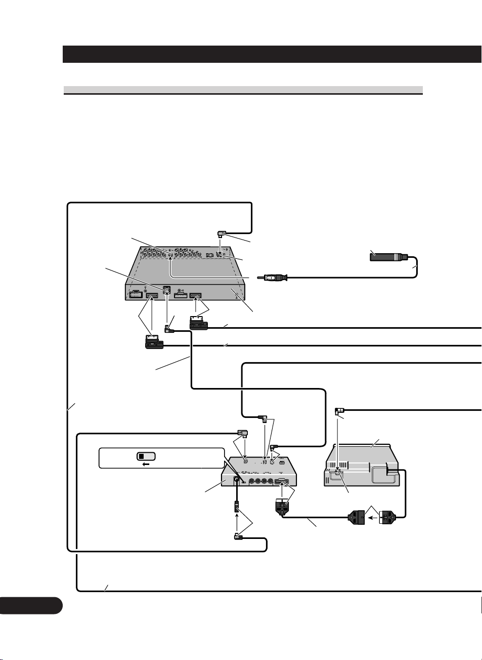
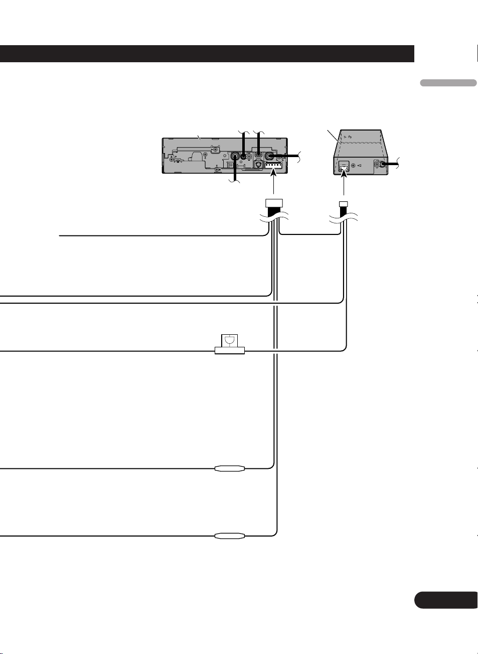
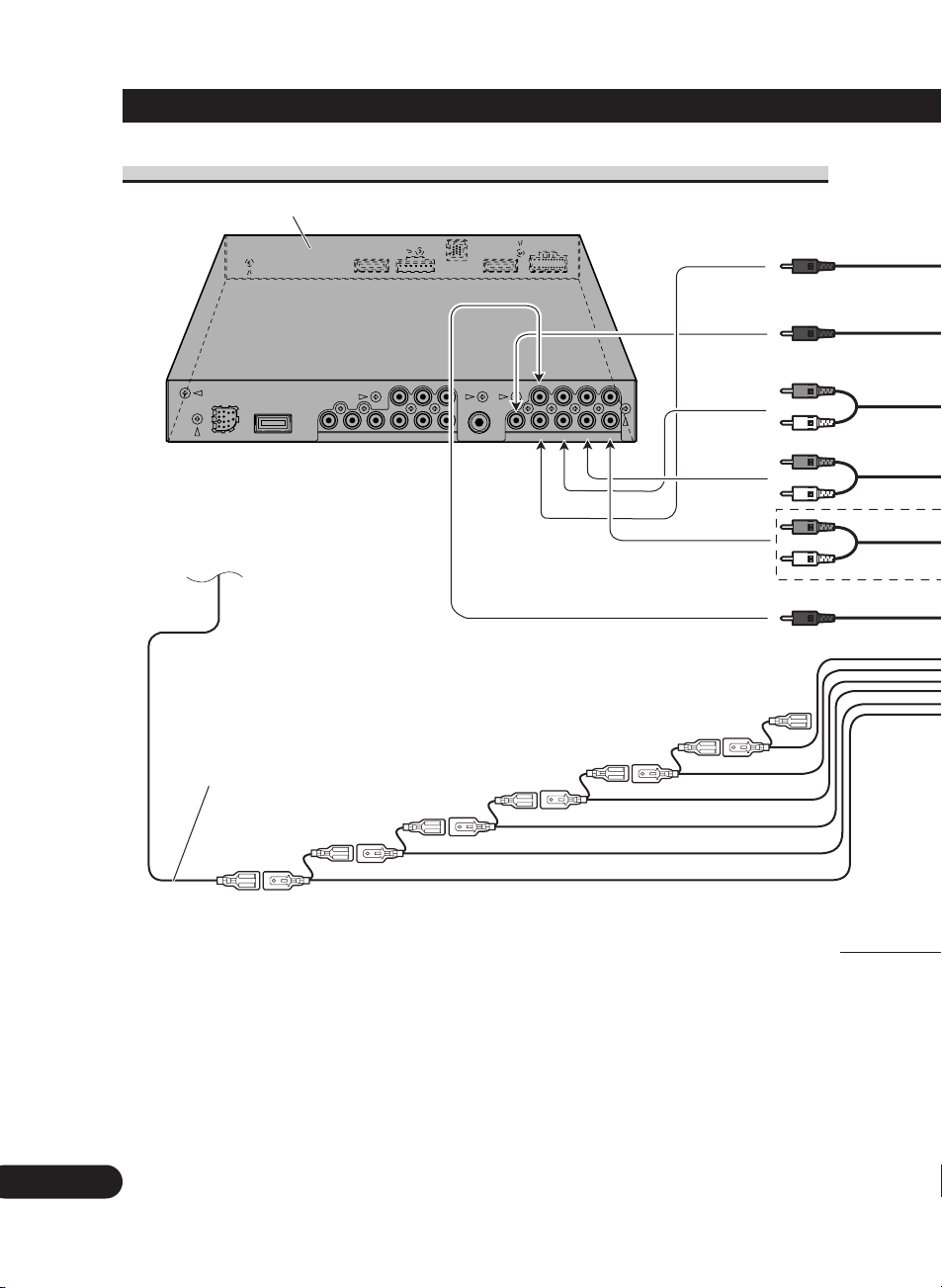
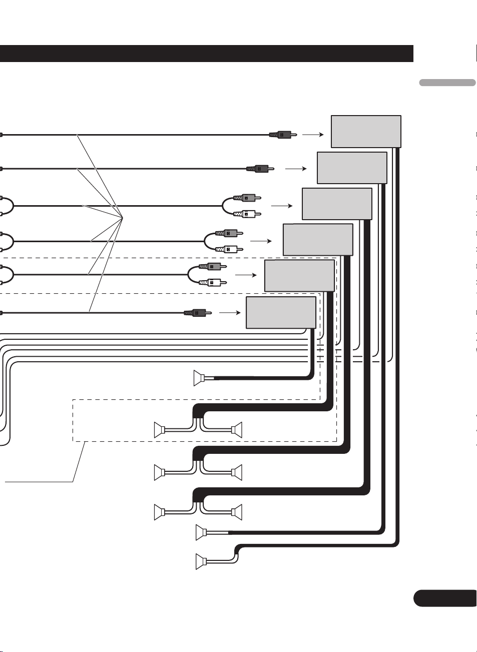
Connecting the system
Blue
Violet
6 m
6 m
Hide-away unit (supplied)
Black
Black
STAND ALONEIP BUS
25 pin cable (supplied with XDV-P650)
Depending on where you install,
this cable is not used.
Black
Black
AV-BUS cable (supplied
with XDV-P650)
Black
Black
IP-BUS input
(Blue)
AV-BUS cable (supplied
with TV tuner)
Blue
Antenna jack
Antenna cable (supplied)
6 m
AV-BUS input (Blue)
IP-BUS cable
(supplied with XDV-P650)
Blue
Blue
Blue
Hide-away unit
(supplied with XDV-P650)
XDV-P650
(sold separately)
<CRD4229-A> 5
English
Español
Deutsch
Français
Italiano
Nederlands
PyТТНЛИ
Fig. 2
4
ENG/MASTER 96 INST
Black
Blue
Black
Violet
Blue
40 cm
15 cm
40 cm
1 m
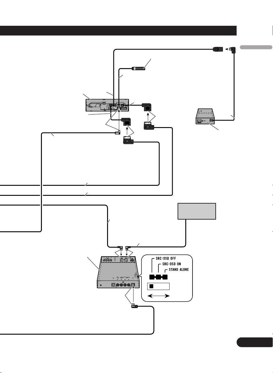
This product
Power supply box
(supplied)
Blue
IP-BUS cable
Multi-CD player
(sold separately)
Hide-away TV tuner
(e.g. GEX-P5750TV(P))
(sold separately)
IP-BUS cable (supplied
with TV tuner)
Microphone/auxiliary input jack (3.5 ø)
(MIC/AUX IN)
1.5 m
30-pin cable (supplied)
30-pin cable (supplied)
Optical cable
(e.g. CD-AD600)
(sold separately)
Before installing this unit to your
vehicle, pull out the jack to the place
where you can easily plug in/out the
microphone or stereo mini plug cable.
Use a stereo mini plug cable to connect
with auxiliary equipment.
5
Connecting the Units
Connecting the power cord (1)
If this unit is used with more than a 6-ch speaker system, be sure to connect the yellow
lead to the battery terminal directly.
ENG/MASTER 96 INST
6
<CRD4229-A> 6
Yellow
After making all other connections to this unit,
connect this to the positive + terminal of the battery.
CAUTION
Attach a 20 A fuse immediately prior to the battery.
Also, use heat resistant battery cable with more
than 5 mm2 sectional area.
Black (chassis ground)
Connect to a clean, paint-free metal location.
Red
Connect to terminal controlled by
ignition switch (12 V DC).
Orange/white
Connect to lighting switch terminal.
6
ENG/MASTER 96 INST
English
Español
Deutsch
Français
Italiano
Nederlands
PyТТНЛИ
<CRD4229-A> 7
Fig. 3
Fuse resistor
Fuse resistor
Fuse (7.5 A)
This product
Power supply box
(supplied)
Yellow/black
If you use equipment with Mute function, wire
this lead to the Audio Mute lead on that piece of
equipment. If not, keep the Audio Mute lead free
of any connections.
7
Connecting the Units
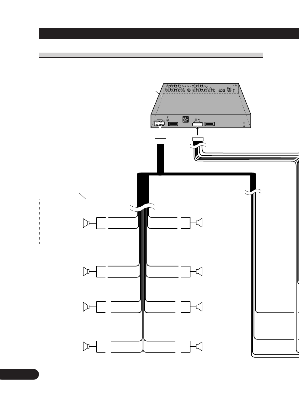
Connecting the power cord (2)
If this unit is used with more than a 6-ch speaker system, be sure to connect the yellow
lead to the battery terminal directly.
ENG/MASTER 96 INST
8
<CRD4229-A> 8
Front speaker
(MID/FRONT
OUTPUT)
Rear speaker
Front speaker
(MID/FRONT
OUTPUT)
Rear speaker
White
White/black
Gray
Gray/black
Green
Green/black
Violet
Violet/black
Hide-away unit (supplied)
+
≠
+
≠
+
≠
+
≠
+
≠
+
≠
+
≠
+
≠
Left Right
Left Right
Left Right
Tweeter
(FRONT HIGH
OUTPUT)
Front center speaker
(FRONT CENTER
OUTPUT)
Rear center speaker
(REAR CENTER
OUTPUT)
Tweeter
(FRONT HIGH
OUTPUT)
White
White/black
Gray
Gray/black
Black/white
Black
Black/white
Black
Connect when the audio settings of this
product are used in the network mode.
8
ENG/MASTER 96 INST
English
Español
Deutsch
Français
Italiano
Nederlands
PyТТНЛИ
<CRD4229-A> 9
Fig. 4
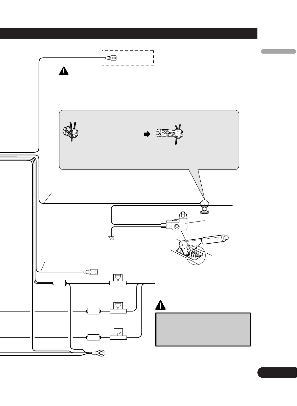
WARNING
Violet/white
See the section “When
connecting with a rear view
camera”.
Note:
• The position of the parking brake switch depends
on the vehicle model. For details, consult the
vehicle Owner’s Manual or dealer.
Connection method
1. Clamp the lead. 2. Clamp firmly with
needle-nosed
pliers.
Light green
Used to detect the ON/OFF status of the parking brake.
This lead must be connected to the power supply side of the parking
brake switch.
Power supply side
Ground side
Black (chassis ground)
Connect to a clean, paint-free metal location.
Fuse (10 A)
Fuse (10 A)
Parking brake
switch
LIGHT GREEN LEAD AT POWER CONNECTOR IS DESIGNED TO DETECT
PARKED STATUS AND MUST BE CONNECTED TO THE POWER SUPPLY SIDE
OF THE PARKING BRAKE SWITCH. IMPROPER CONNECTION OR USE OF THIS
LEAD MAY VIOLATE APPLICABLE LAW AND MAY RESULT IN SERIOUS
INJURY OR DAMAGE.
Fuse (4 A)
Blue/white
Connect to system control terminal of the
power amp or auto-antenna relay control
terminal (max. 300 mA 12 V DC).
Yellow
After making all other connections to this unit,
connect this to the positive + terminal of the
battery.
CAUTION
Attach a 20 A fuse immediately prior to
the battery. Also, use heat resistant
battery cable with more than 5 mm2
sectional area.
<CRD4229-A> 10
When connecting to separately sold power amp
9
Connecting the Units
ENG/MASTER 96 INST
10
Hide-away unit (supplied)
System remote control
Connect when the audio settings of this
product are used in the network mode.
See the section “Connecting the power
cord (2)”.
Blue/white
Connect to system control terminal of the
power amp or auto-antenna relay control
terminal (max. 300 mA 12 V DC).
<CRD4229-A> 11
English
Español
Deutsch
Français
Italiano
Nederlands
PyТТНЛИ
Fig. 5
10
ENG/MASTER 96 INST
Power amp
(sold separately)
Power amp
(sold separately)
Power amp
(sold separately)
RCA cables
(sold separately)
Subwoofer
Front middle range
speaker
Rear speaker
Rear center speaker
Left Right
Power amp
(sold separately)
Power amp
(sold separately)
Power amp
(sold separately)
Front middle range
speaker
Rear speaker
Tweeter
Front center speaker
Tweeter

<CRD4229-A> 12
11
Connecting the Units
ENG/MASTER 96 INST
When connecting with a rear view camera
When using this product with a rear view camera, automatic switching to video from a
rear view camera when the gear shift is moved to REVERSE (R) position is possible.
WARNING:
• USE INPUT ONLY FOR REVERSE OR MIRROR IMAGE REAR VIEW CAMERA.
OTHER USE MAY RESULT IN INJURY OR DAMAGE.
CAUTION:
• The screen image may appear reversed.
• The rear view camera function is to be used as an aid for backing into a tight parking
spot. Do not use this function for entertainment purposes.
• Objects in the rear view may appear closer or more distant than they actually are.
 Loading...