

Muting controller
Up to Category 4, EN 954-1
PMUT X1P
Gertebild
][Bildunterschrift_Muting
Unit for the temporary suspension of
safety functions (muting)
Approvals
PMUT X1P
SÜDDEUTSCHLAND
Zulassungen
Unit features
Gertemerkmale
` Positive-guided relay outputs:
– 3 safety contacts (N/O), instanta-
neous
– 1 auxiliary contact (N/C), instan-
taneous
` 4 inputs for muting sensors
` 1 ESPE input (2channel)
` 1 input for additional safety light
barrier (dual-channel) or safety contacts
` 2 muting lamps
` Connection options for
– Reset button
– Key switch
– Feedback loop
` Monitors muting lamps
` Muting mode: sequential or parallel
` LED indicators for
– Switch status channel 1/2
– Muting sensors
– Light barrier
– Simultaneity requirement
– Muting lamp error
` Semiconductor outputs signal:
– Switch status channel 1/2
–Muting active
– One of the muting lamps defec-
tive
– Both muting lamps defective
– Light barrier (ESPE) active
` Plug-in connection terminals (either
spring-loaded terminal or screw
terminal)
` See order reference for unit types
Unit description
Bestimmung/Gertebeschreibung_Muting_PDB
The muting controller meets the requirements of EN 60204-1.
It may be used in safety circuits which
temporarily suspend safety functions
(muting), in accordance with
EN 61496-1.
Safety features
][Sicherheitseigenscha ften Schaltgerät_allgem einer Teil
The relay meets the following safety
requirements:
` The circuit is redundant with built-in
self-monitoring.
` The safety function remains effec-
tive in the case of a component failure.
` The correct opening and closing of
the safety function relays is tested
automatically in each on-off cycle.
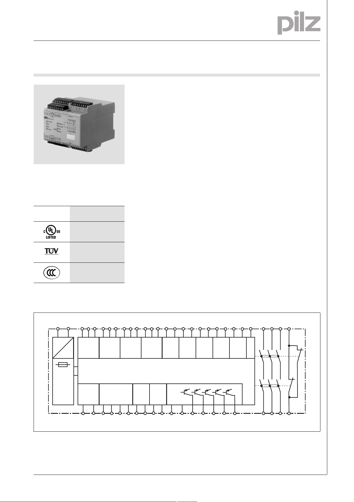
Block diagram
A1 A2
=
Power
=
S1+ S1 S1-
Input
MS1
Feed-
back
Y1 Y2
Blockschaltbild
S2+ S2 S2-
LA+ LA- LB+ LB-
Input
MS2
Lamp
S3+ S3 S3-
Input
MS3
S4+ S4 S4-
Input
MS4
Start
Reset
S33 S34 S43 S44
S11 S12
Input 1
0 V 24 V
Y30 Y31
S21 S22
S31 S32
Input 2
Input 3
Y32 Y33 Y34 Y35 Y36
S51 S52
Input 4
S61 S62
Input 5
GND
GND
K1
K2
23 33 41
13
14 24 34 42
Pilz GmbH & Co. KG, Felix-Wankel-Straße 2, 73760 Ostfildern, Germany
Telephone: +49 711 3409-0, Telefax: +49 711 3409-133, E-Mail: pilz.gmbh@pilz.de
NSG-D-2-305-2010-08
Muting controller
Up to Category 4, EN 954-1
PMUT X1P
Function description
][Funktionen_Muting
` Dual-channel operation (contact or
semiconductor outputs from ESPE)
without detection of shorts between contacts
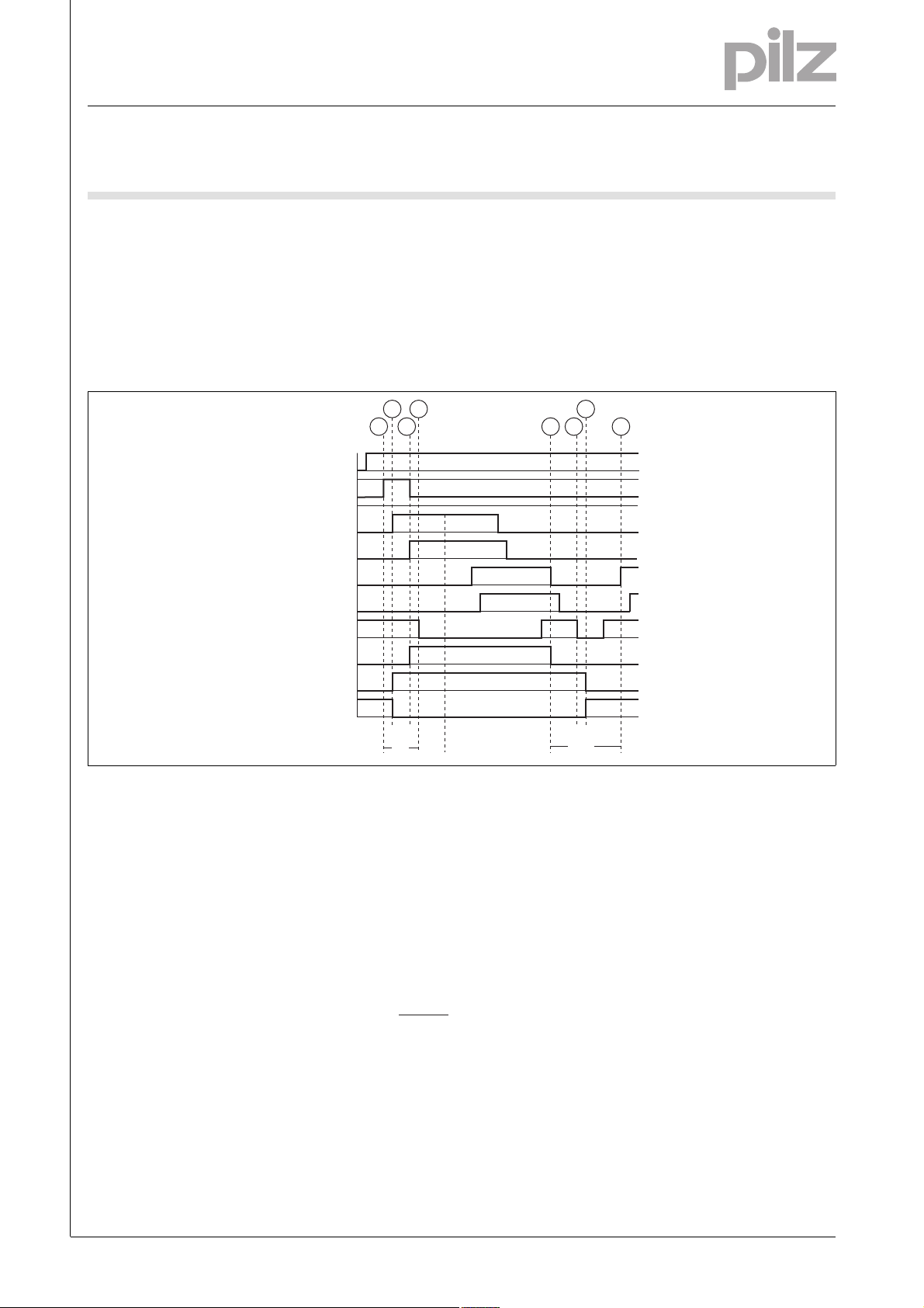
Timing diagram
POWER
Reset/Start
Output safe
` Dual-channel operation (contact or
semiconductor outputs from ESPE)
with detection of shorts between
contacts: Redundant input circuit,
earth faults in the input circuit or
shorts between the input circuits
are detected.
][Zeitdiagramm_muting
4
123
MS1
MS2
MS3
MS4
BWS
ML
5 4
` Monitored manual reset. Supply
voltage must be present before the
reset contact is closed. The unit is
not active until the reset button has
been operated.
6
3
Output aux
Key
` Power: Supply voltage
` Reset/start: Reset button
` ESPE: Light barrier
` MS1 ... MS2: Muting sensors
` ML: Muting lamps
` Output Safe: Safety contacts 13-
14, 23-24, 33-34
` Output aux: Auxiliary contact 41-42
Wiring
][Verdrahtung_Si_unverz_1Hi_unverz
Please note:
` Information given in the “Technical
details” must be followed.
` Outputs 13-14, 23-24, 33-34 are
safety contacts, output 41-42 is an
auxiliary contact (e.g. for display).
` To prevent contact welding, a fuse
should be connected before the
output contacts (see technical details).
` Calculation of the max. cable runs
in the input circuit:
l
max
t1
t3
t2
` c: Operate reset button
` d: Close safety contacts
` e: Muting on
` f: Light barrier interrupted
` g: Muting off
` h: Open safety contacts
: Switch-on delay of safety con-
` t
1
tacts
R
lmax
=
I
max
Rl / km
= max. overall cable resist-
R
lmax
ance (see technical details)
/km = cable resistance/km
R
l
` Use copper wire that can withstand
60/75 °C.
` Sufficient fuse protection must be
provided on all output contacts with
capacitive and inductive loads.
][Verdrahtung_Zusatz_Muting
t5
t4
: Minimum start pulse duration
` t
2
: Minimum period before light bar-
` t
3
rier may be interrupted
: Recovery time after muting off
` t
4
: Delay-on de-energisation
` t
5
` Mechanical and optoelectronic
sensors (safety light barriers, safety
light guards) are suitable for use.
` The safety contacts can be used to
shutdown the hazardous movement.
` Only safe contact outputs (e.g. from
safety light barriers) may be used
on S51-S52 and S61-S62. Do not
connect safety light barriers to
semiconductor outputs.
Telephone: +49 711 3409-0, Telefax: +49 711 3409-133, E-Mail: pilz.gmbh@pilz.de
NSG-D-2-305-2010-08Pilz GmbH & Co. KG, Felix-Wankel-Straße 2, 73760 Ostfildern, Germany
-2
Muting controller
Up to Category 4, EN 954-1
PMUT X1P
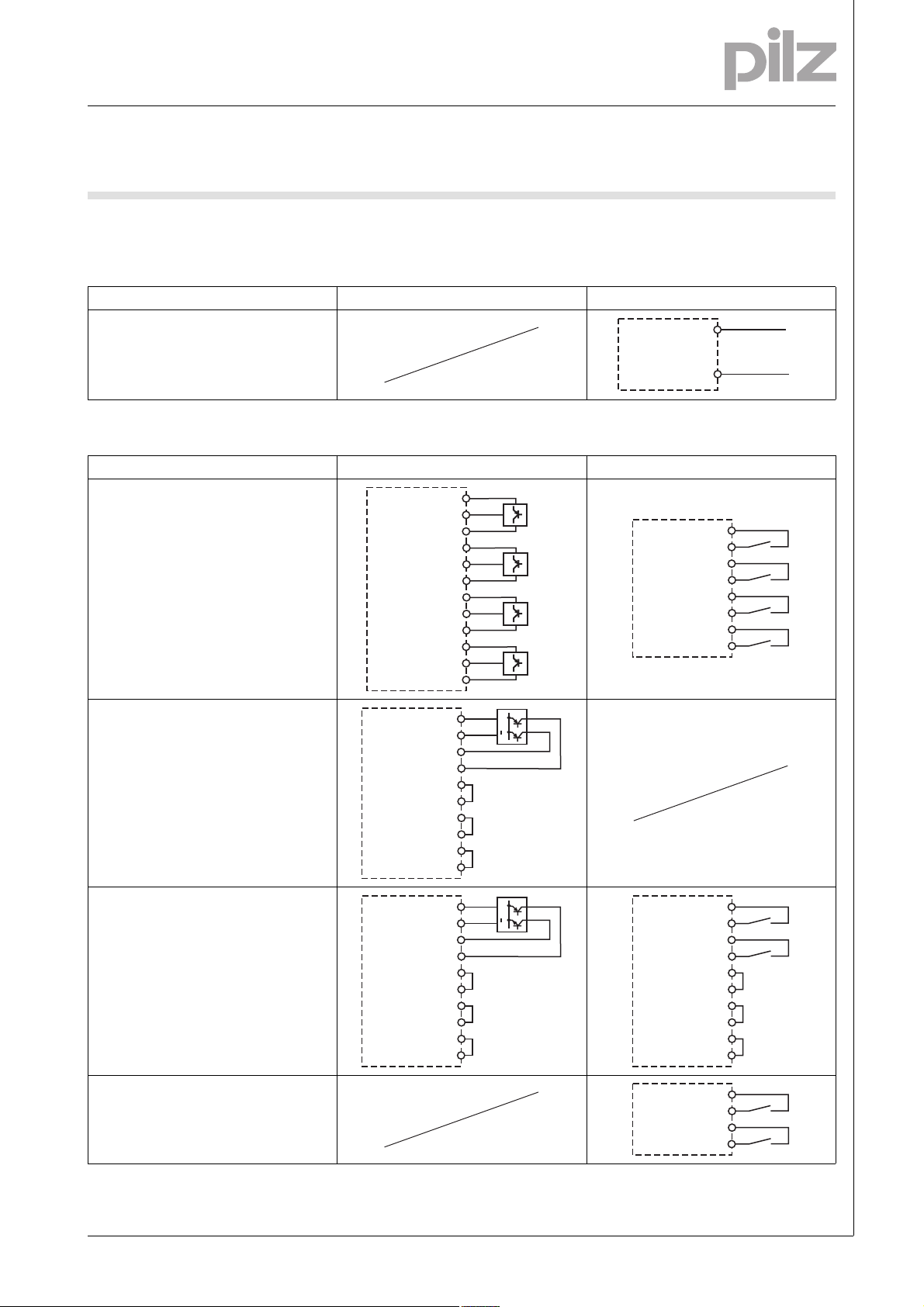
Preparing for operation
Betriebsbereitschaft her stellen
` Supply voltage
Supply voltage AC DC
` Input circuit
Input circuit Semiconductor Contacts
Muting sensors
24 V DC
Input
0 V
24 V DC
Input
0V
24 V DC
Input
0 V
24 V DC
Input
0 V
S1+
S1
S1S2+
S2
S2S3+
S3
S3S4+
S4
S4-
MS1
MS2
MS3
MS4
24 V DC
Input
24 V DC
Input
24 V DC
Input
24 V DC
Input
A1
A2
S1+
S1
S2+
S2
S3+
S3
S4+
S4
L+
L-
MS1
MS2
MS3
MS4
Light beam device (ESPE)
Semiconductor output 2 x PNP
Light beam device detects shorts across
contacts
Light beam device (ESPE)
Semiconductor output PNP/NPN
Detection of shorts across contacts;
- Semiconductor: via light beam device
- Contacts: via PMUT X1P
Additional light beam device, dual-channel,
E-STOP pushbutton
24 V DC
0 V
Input
Input
24 V DC
0 V
Input
Input
S11
GND
S22
S12
S31
S32
S51
S52
S61
S62
S11
GND
S32
S22
S11
S12
S51
S52
S61
S62
+
+
S21
S22
S31
S32
S11
S12
S51
S52
S61
S62
S51
S52
S61
S62
Pilz GmbH & Co. KG, Felix-Wankel-Straße 2, 73760 Ostfildern, Germany
Telephone: +49 711 3409-0, Telefax: +49 711 3409-133, E-Mail: pilz.gmbh@pilz.de
NSG-D-2-305-2010-08

Muting controller
Up to Category 4, EN 954-1
PMUT X1P
` Reset circuit
S1: Key switch
S3: Reset button
S33
S34
S43
S44
S3
S1
` Feedback circuit
Feedback circuit Link Contacts in series to feedback loop
Y1
Y2
Y1
Y2
13 (23, 33)
14 (24, 34)
K5
K6
K5
K6
` Semiconductor output
Y32: Light beam device active
Y33: Muting active
Y34: Muting lamp warning
Y35: Both muting lamps defective
Y36: Safety contacts closed
Y31
Y32
Y33
Y34
Y35
Y36
Y30
24 V DC
SPS Input
SPS Input
SPS Input
SPS Input
SPS Input
0 V
L1
N
Telephone: +49 711 3409-0, Telefax: +49 711 3409-133, E-Mail: pilz.gmbh@pilz.de
NSG-D-2-305-2010-08Pilz GmbH & Co. KG, Felix-Wankel-Straße 2, 73760 Ostfildern, Germany
-4

Muting controller
Up to Category 4, EN 954-1
PMUT X1P
Terminal configuration
A1
A1
S1+
S3+
POWER
S1
S2
S1+S2
S1
S1-
LA+ LA - LB+LB-
P3
S3
S3-
S33 S34
P4
PMUT X1P
S43S44
Klemmenbelegung
Output
ML Fault
CH.1
CH.2
S11 S12
OSSD
13 23 33 41
S32S31
P5
13 23 33 41
14 24 34 42
Installation
Montage_PNOZ_X
` The safety relay should be installed
in a control cabinet with a protection type of at least IP54.
` Use the notch on the rear of the unit
to attach it to a DIN rail.
` Ensure the unit is mounted securely
on a vertical DIN rail (35 mm) by using a fixing element (e.g. retaining
bracket or an end angle).
A2
S4+
S4
S4-
S2+
S2
S2-
Dimensions
Abmessungen
* with spring-loaded terminals
94 (3.70")
* 101 (3.98")
Y35
P1
Y36
S52S51
S21 S22
S61S62
GND
P5
14 24 34 42A2
Y2
P4
Y31
Y30
Y1
P3
Y34Y33Y32
121 (4.76")
90
(3.54")
Pilz GmbH & Co. KG, Felix-Wankel-Straße 2, 73760 Ostfildern, Germany
Telephone: +49 711 3409-0, Telefax: +49 711 3409-133, E-Mail: pilz.gmbh@pilz.de
NSG-D-2-305-2010-08

Muting controller
Up to Category 4, EN 954-1
PMUT X1P
Notice
][WICHTIG_PDB_al t
This data sheet is only intended for use
during configuration. For installation
and operation, please refer to the operating instructions supplied with the
Service life graph
10
AC15: 230 V
unit.
DC13: 24 V
1
D Nennbetriebstrom (A)
GB Nominal operating current (A)
F Courant coupé (A)
Technische Daten
Technical details
Electrical data
Supply voltage
Supply voltage U
DC 24 V
B
Voltage tolerance -15 %/+10 %
Power consumption at U
DC 6.0 W
B
Residual ripple DC 48 %
Voltage and current at
Input circuit DC: 24.0 V 25.0 mA
Reset circuit DC: 24.0 V 40.0 mA
Feedback loop DC: 24.0 V 40.0 mA
Muting lamp DC: 24.0 V 500 mA
Muting sensor DC: 24.0 V 40 mA
Max. power consumption
Muting sensors 5 W
Light barrier 10 W
Muting lamp 12 W
Number of output contacts
Safety contacts (S) instantaneous: 3
Auxiliary contacts (N/C): 1
Utilisation category in accordance with EN 60947-4-1
Safety contacts: AC1 at 240 V I
Safety contacts: DC1 at 24 V I
Auxiliary contacts: AC1 at 240 V I
Auxiliary contacts: DC1 at 24 V I
Utilisation category in accordance with EN 60947-5-1
Safety contacts: AC15 at 240 V I
Safety contacts: DC13 at 24 V (6 cycles/min) I
Auxiliary contacts: AC15 at 230 V I
Auxiliary contacts: DC13 at 24 V (6 cycles/min) I
Contact material AgSnO2 + 0.2 µm Au
0.1
E Corriente nominal de servicio (A)
I Corrente di esercizio nominale (A)
NL Nominale bedrijfsstroom (A)
10 100 1000 10000
D Schaltspielzahl x 10
GB Cycles x 10
F Nombre de manuvres x 10
: 0.01 A , I
min
P
: 2000 VA
max
: 0.01 A , I
min
P
: 200 W
max
: 0.01 A , I
min
: 2000 VA
P
max
: 0.01 A , I
min
P
: 200 W
max
: 5.0 A
max
: 5.0 A
max
: 5.0 A
max
: 5.0 A
max
3
3
: 8.0 A
max
max
max
max
Lebensdauerkurve
: 8.0 A
: 8.0 A
: 8.0 A
DC1: 24 V
AC1: 230 V
E Número de ciclos x 10
I Numero dei cicli di commutazione x 10
3
NL Aantal schakelingen x 10
3
3
3
Telephone: +49 711 3409-0, Telefax: +49 711 3409-133, E-Mail: pilz.gmbh@pilz.de
NSG-D-2-305-2010-08Pilz GmbH & Co. KG, Felix-Wankel-Straße 2, 73760 Ostfildern, Germany
-6

Muting controller
Up to Category 4, EN 954-1
PMUT X1P
Electrical data
External contact fuse protection (IK = 1 kA) to EN 60947-5-1
Blow-out fuse, quick
Safety contacts: 10 A
Auxiliary contacts: 10 A
Blow-out fuse, slow
Safety contacts: 6 A
Auxiliary contacts: 6 A
Circuit breaker 24 VAC/DC, characteristic B/C
Safety contacts: 6 A
Auxiliary contacts: 6 A
Semiconductor outputs (short circuit proof) 24.0 V DC, 20 mA
External supply voltage 24.0 V DC
Voltage tolerance -20 %/+20 %
Max. overall cable resistance R
input circuits, reset circuits
dual-channel without detect. of shorts across contacts at U
dual-channel with detect. of shorts across contacts at U
Min. input resistance in the starting torque 460 Ohm
Times
Switch-on delay
on monitored reset with rising edge typ. 40 ms
on monitored reset with rising edge max. 80 ms
Muting typ. 35 ms
Muting max. 80 ms
Delay-on de-energisation
with E-STOP typ. 15 ms
with E-STOP max. 30 ms
with power failure typ. 490 ms
with power failure max. 700 ms
with power failure during muting typ. 125 ms
with power failure during muting max. 180 ms
Recovery time at max. switching frequency 1/s
after E-STOP 50 ms
after power failure 720 ms
after muting sensors off 300 ms
Waiting period with a monitored reset
with rising edge 300 ms
Min. start pulse duration with a monitored reset
with rising edge 40 ms
Simultaneity, channel 1 and 2 3 s
Supply interruption before de-energisation 20 ms
Supply interruption before de-energisation in the input circuit 4.0 ms
Environmental data
EMC EN 61000-6-2, EN 61496-1
Vibration to EN 60068-2-6
Frequency 10 - 55 Hz
Amplitude 0.35 mm
Climatic suitability EN 60068-2-78
Airgap creepage in accordance with EN 60947-1
Pollution degree 2
Overvoltage category III
Ambient temperature -10 - 55 °C
Storage temperature -40 - 85 °C
Protection type
Mounting (e.g. cabinet) IP54
Housing IP40
Terminals IP20
lmax
DC 70 Ohm
B
DC 15 Ohm
B
Pilz GmbH & Co. KG, Felix-Wankel-Straße 2, 73760 Ostfildern, Germany
Telephone: +49 711 3409-0, Telefax: +49 711 3409-133, E-Mail: pilz.gmbh@pilz.de
NSG-D-2-305-2010-08

Muting controller
Up to Category 4, EN 954-1
PMUT X1P
Mechanical data
Housing material
Housing PPO UL 94 V0
Front ABS UL 94 V0
Cross section of external conductors with screw terminals
1 core flexible 0.20 - 2.50 mm² , 24 - 12 AWG No. 778010
2 core, same cross section, flexible:
with crimp connectors, without insulating sleeve 0.20 - 1.00 mm² , 24 - 16 AWG No. 778010
without crimp connectors or with TWIN crimp connectors 0.20 - 1.50 mm² , 24 - 16 AWG No. 778010
Torque setting with screw terminals 0.50 Nm No. 778010
Cross section of external conductors with spring-loaded terminals: Flexible with/without crimp connectors
Spring-loaded terminals: Terminal points per connection 2 No. 788010
Stripping length 8 mm No. 788010
Dimensions
Height 101.0 mm No. 788010
Width 90.0 mm
Depth 121.0 mm
Weight 550 g No. 788010
Technische Daten_Satz No rmen
The standards current on 2007-01 apply.
][Dauerstrom_DC
0.20 - 1.50 mm² , 24 - 16 AWG No. 788010
94.0 mm No. 778010
560 g No. 778010
Conventional thermal current
(A) at UBDC
I
th
1 contact 8.00 A
2 contacts 6.00 A
3 contacts 5.00 A
Order reference
Type Features Terminals Order no.
PMUT X1P C 24 VDC Spring-loaded terminals 788 010
PMUT X1P 24 VDC Screw terminals 778 010
Bestelldaten
Telephone: +49 711 3409-0, Telefax: +49 711 3409-133, E-Mail: pilz.gmbh@pilz.de
NSG-D-2-305-2010-08Pilz GmbH & Co. KG, Felix-Wankel-Straße 2, 73760 Ostfildern, Germany
-8
 Loading...