

Page 1
Electronic monitoring relays PMDsigma
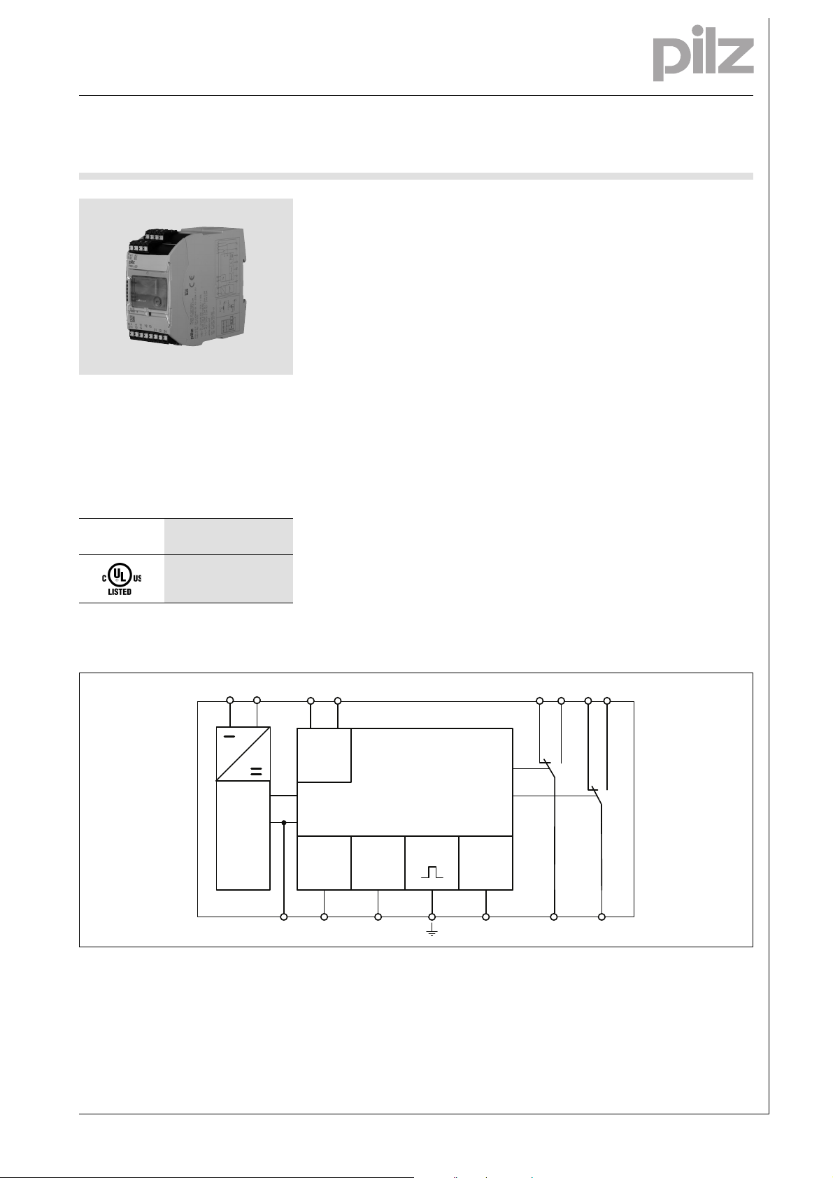
U
M
A1 A2
~
Power
B1 B2
Reset Test
G
Feedback
Earth
Y1 Y2 Y3
K1
K2
11 21
12 14 22 24
+
-
FE
Insulation monitor
PMD s20
Gertebild
Bildunterschrift
The insulation monitor monitors the insulation resistance of unearthed AC/
DC systems (IT systems). It meets the
requirements of EN 61557-8, IEC
60364-7-710 and DIN VDE 0100-710.
Approvals
PMD s20
Zulassungen
Unit features
Gertemerkmale
Relay output:
2 auxiliary changeover contacts (C/
O)
Detects symmetrical and asymmet-
rical insulation faults
Two insulation measuring circuits
Connection for external switch con-
tacts to trigger the manual reset
and for function testing
Unit parameter settings are menu-
driven and infinitely variable via a
display and rotary encoder with key
function (turn and push)
Configuration is stored on a chip
card
Status indicators (LEDs) for:
– Supply voltage (Power)
– Insulation resistance
–Fault
Unit description
Gertebeschreibung
The insulation monitor monitors the insulation resistance of unearthed AC/
DC systems (IT systems). It meets the
requirements of EN 61557-8,
IEC 60364-7-710 and DIN VDE 0100710 and may be used:
To monitor unearthed AC/DC sys-
tems (including on board ships)
In medical locations
As a trip device if insulation resist-
ances are outside the permitted
range
Block diagram
Blockschaltbild
1001753-EN-02-2011-05
Page 2
Electronic monitoring relays PMDsigma
R
an
UB
t
t
LED
t
tr
0
1
R
ab
t
R
E
t
Reset
t
tr
tr
Auto reset
Manual reset
0
1
11
-
14
21
-
24
11
14
21 24
-
-
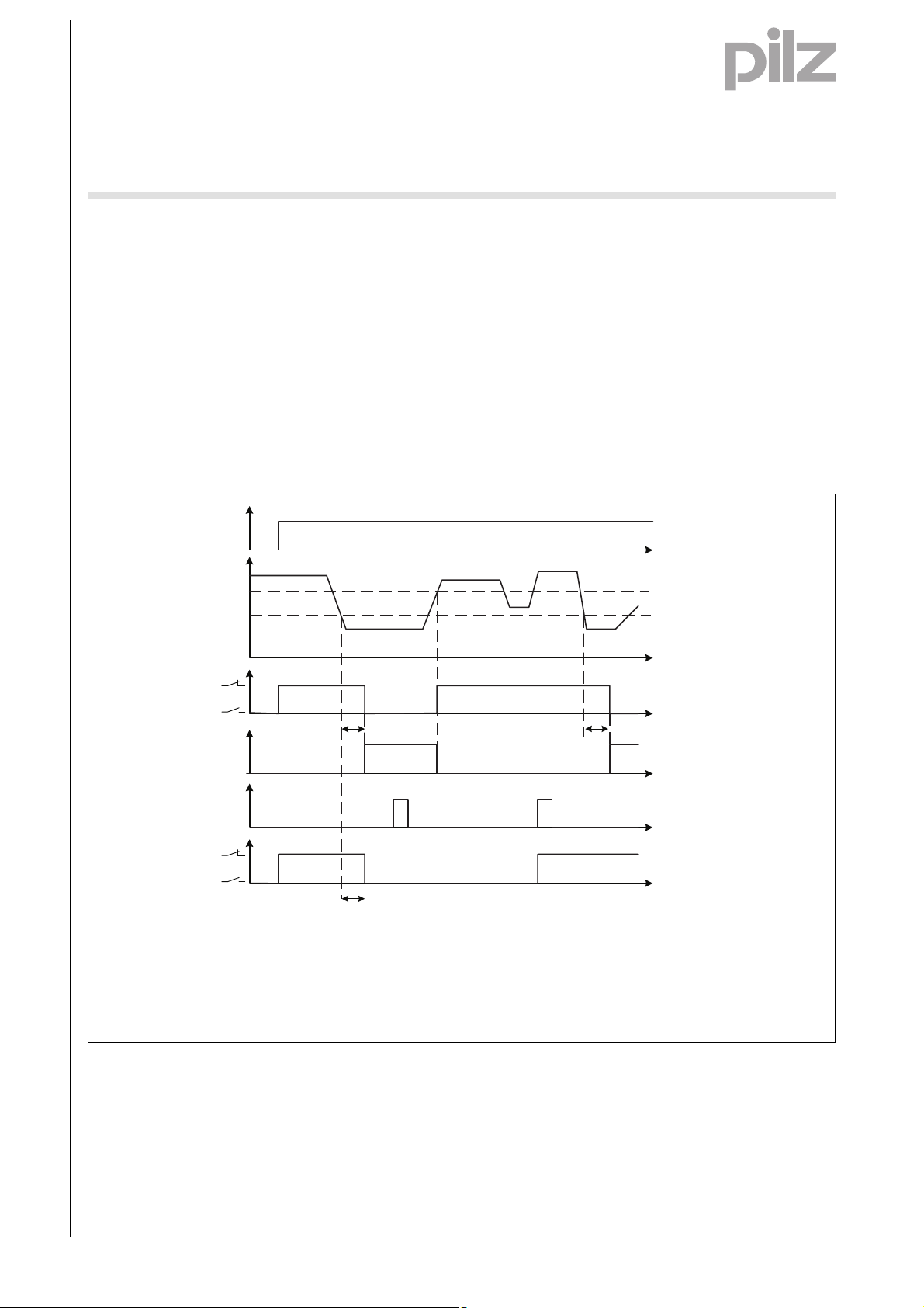
Hysteresis
UB = Versorgungsspannung/Supply voltage/Tension d'alimentation
R
an
= Ansprechwert/Response value/Seuil de déclenchement
R
ab
= Rücksetzwert/Release value/Valeur de réarment
R
E
= Isolationswiderstand/Insulation resistance/Résistance de'isolement
Insulation monitor
PMD s20
Function description
Funktionsbeschre ibung PMS s20
The insulation monitor prevents hazardous insulation faults in galvanically
separated systems. The insulation resistances are measured between the
network phases and the operating
earth. The measuring principle detects
symmetrical and asymmetrical insulation faults.
Relay outputs (K1 and K2)
K1 and K2 operate in normally energised mode. In their default state, aux-
Timing diagram
iliary contacts 11-14 and 21-24 are
closed and auxiliary contacts 11-12
and 21-22 are open. Normally energised mode is the default setting; this
setting can be changed via the menu.
Response resistance
If the insulation resistance falls below
the set response resistance R
an
ther of the two measuring circuits (R
< R
), the LED "Out 1" or "Out 2" will
an
light and the relay contacts will de-energise.
Funktionsdiagram PMD s20
in ei-
Response resistance Ran1:
Auxiliary contacts 11-14 will open
and auxiliary contacts 11-12 will
close (normally energised mode).
Response resistance Ran2:
Auxiliary contacts 21-24 will open
and auxiliary contacts 21-22 will
close (normally energised mode).
Monitoring the operating earth
E
If the connection between the operating earth and the FE terminal is broken, contacts 11-12 and 21-22 will
close (normally energised mode).
Wiring
Inbetriebnahme _Isolationswäch ter
When commissioning, please note the
following:
Output contacts 11-12-14 and 21-
22-24 are auxiliary contacts (e.g. for
a display or contactor control)
Only wire the unit when the supply
voltage is switched off!
Use copper wiring.
To prevent contact welding, a fuse
should be connected before the
output contacts (see technical details).
Ensure that the cables are laid care-
fully, because an open circuit in the
measuring circuit will cause the unit
to malfunction.
Ensure there is adequate fuse pro-
tection on the connection cables at
terminals B1 and B2.
1001753-EN-02-2011-05
Page 3
Electronic monitoring relays PMDsigma
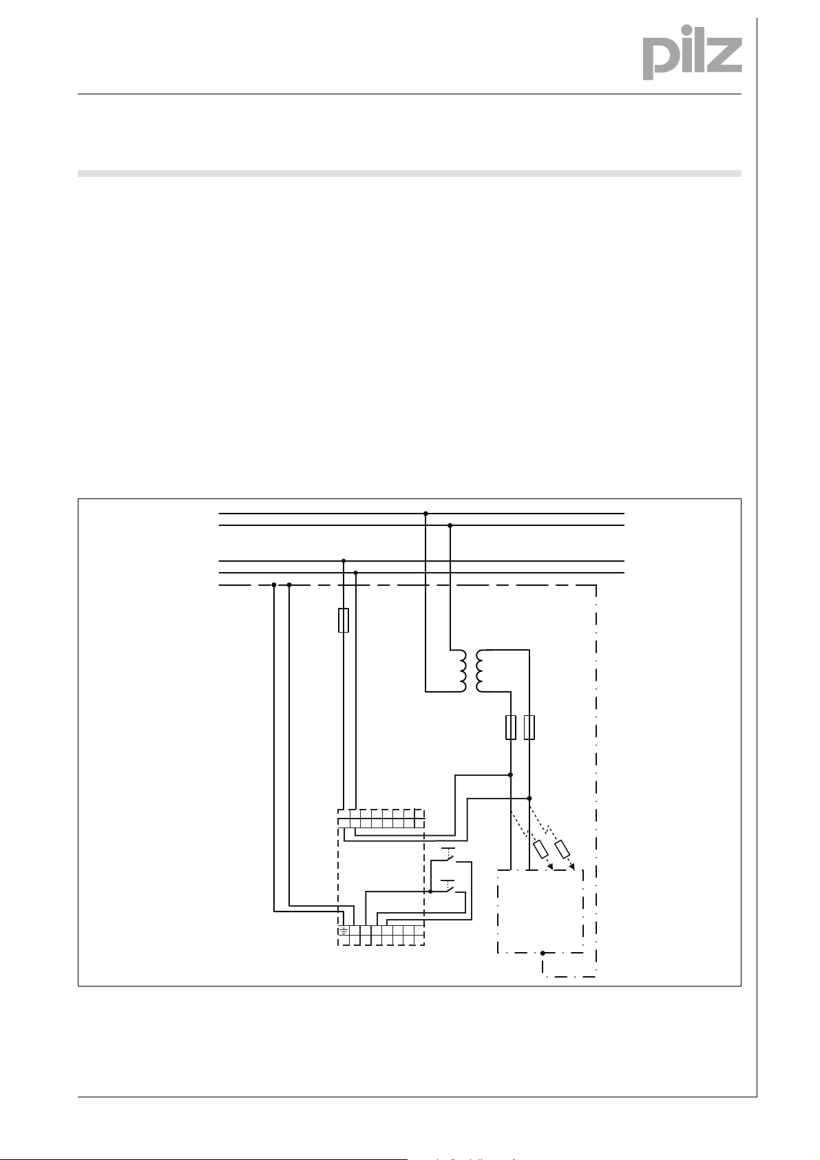
L1
N
PE
1L1
1L2
E1
R
e
R
e
F1
F2
T1
Test
Y3
Reset
12
14
11
A1
A2
24
22
21
Y1
Y2
B1
B2
FE
PMD s20
Insulation monitor
PMD s20
Only one insulation monitor should
be connected to galvanically connected systems.
Preparing for operation
Inbetriebnahme_Anschluss
Supply voltage UB:
– Connect the supply voltage UB
to A1/A2. The supply voltage UB
can also be taken from the
measuring circuit.
Measuring circuit (system to be
monitored):
– 2-phase system:
– Connect one phase of the moni-
tored system to the terminals
Application circuit AC
A function test involving a real earth
fault (resistance) must be carried
out in order to check that the unit is
properly connected.
B1/B2 respectively.
– 3-phase system:
– Link terminals B1/B2 and con-
nect them to the system's star
point.
Connect the output contacts in ac-
cordance with the relevant application circuit.
Function test:
– By pressing a button at terminals
Inbetriebnahme_Anwendung_Bild_1
Information given in the “Technical
details” must be followed.
Y1 and Y3
or
– Pressing the rotary knob for at
least 3 seconds
Leerzeilen
Inbetriebnahme
Please note:
Do not connect any cables to undesignated terminals.
1001753-EN-02-2011-05
Page 4

Electronic monitoring relays PMDsigma
L1
N
PE
E1
R
e
R
e
F1
F2
T1
~
=
G1
Test
Y3
Reset
12
14
11
A1
A2
24
22
21
Y1
Y2
B1
B2
FE
1L1
1L2
PMD s20
Insulation monitor
PMD s20
Application circuit DC
Inbetriebnahme_Anwendung_Bild_2
1001753-EN-02-2011-05
Page 5

Electronic monitoring relays PMDsigma
L1
L2
PE
1L1
1L2
E1
R
e
L3
R
e
F2
F1
T1
Test
Y3
Reset
12
14
11
A1
A2
24
22
21
Y1
Y2
B1
B2
FE
PMD s20
Insulation monitor
PMD s20
Application circuit 3 AC
Inbetriebnahme_Anwendung_Bild_3
1001753-EN-02-2011-05
Page 6

Electronic monitoring relays PMDsigma
L1
L2
1L1
1L2
E1
PE
L3
R
e
F1
F2
G1
T1
alternativ
alternative
alternatif
Test
Y3
Reset
12
14
11
A1
A2
24
22
21
Y1
Y2
B1
B2
FE
PMD s20
Insulation monitor
PMD s20
Application circuit 3 AC/DC
Inbetriebnahme_Anwendung_Bild_4
Inbetriebnahme
Parameter setting
Inbetriebnahme_Drehknop f_Funktion
The menu settings are made on the
unit's display via a rotary knob. You
have the option to make the settings
Installation
Montage_Sigma_allgemein
The unit should be installed in a
control cabinet with a protection
type of at least IP54.
Use the notch on the rear of the unit
to attach it to a mounting rail.
In environments exposed to heavy
vibration or when installing on a vertical mounting rail (35 mm), the unit
should be secured using a fixing element (e.g. retaining bracket or end
angle).
Push the unit upwards or down-
wards before lifting it from the
mounting rail.
on the knob by hand or with a screwdriver. If you make the settings with a
screwdriver, the knob can remain
within the unit.
1001753-EN-02-2011-05
Page 7

Electronic monitoring relays PMDsigma
Insulation monitor
PMD s20
Notice
][WICHTIG_PDB_alt
This data sheet is only intended for use
during configuration. For installation
and operation, please refer to the op-
Montage
Technische Daten_P MDs20
erating instructions supplied with the
unit.
Technical details
Electrical data
Supply voltage UB AC/DC 24 - 240 V
Voltage tolerance -15 %/+10 %
Power consumption at U
Power consumption at U
Frequency range AC 50 - 60 Hz
Residual ripple DC 20 %
Utilisation category in accordance with EN 60947-4-1
Auxiliary contacts: AC1 at 240 V I
Auxiliary contacts: DC1 at 24 V I
Utilisation category in accordance with EN 60947-5-1
Auxiliary contacts: AC15 at 230 V I
Auxiliary contacts: DC13 at 24 V (6 cycles/min) I
Contact material AgCdO + 3.0 µm Au
External contact fuse protection (I
Blow-out fuse, quick
Auxiliary contacts: 6 A
Blow-out fuse, slow
Auxiliary contacts: 4 A
Measuring circuit
Rated mains voltage 0 ... 400 V
Rated mains voltage in according with UL 0 ... 300 V
Max. external voltage 460 V
Max. measuring voltage U
Max. measuring current I
Min. measuring circuit impedance 250 kOhm
Response value R
an
Max. response error in accordance with EN 61557-8 ±15 % ±1kOhm
Max. leakage capacitance 20 µF
Environmental data
EMC EN 61000-6-2, EN 61000-6-4
Vibration to EN 60068-2-6
Frequency 10 - 55 Hz
Amplitude 0.35 mm
Climatic suitability EN 60068-2-78
Airgap creepage in accordance with EN 60664-1
Pollution degree 2
Overvoltage category III
Rated insulation voltage 250 V
Rated impulse withstand voltage
Auxiliary contacts for the remaining circuits 6.00 kV
Supply voltage, measuring circuit for the remaining circuits 4.0 kV
Ambient temperature -10 - 55 °C
Storage temperature -40 - 85 °C
AC 5.0 VA
B
DC 2.5 W
B
min
P
min
P
max
max
= 1 kA) to EN 60947-5-1
K
M
M
±16 V
1 mA
10 ... 200 kOhm
: 0.10 A , I
: 1200 VA
max
: 0.10 A , I
: 120 W
max
: 3.0 A
: 2.0 A
max
max
: 5.0 A
: 5.0 A
1001753-EN-02-2011-05
Page 8

Electronic monitoring relays PMDsigma
Insulation monitor
PMD s20
Environmental data
Protection type
Mounting (e.g. cabinet) IP54
Housing IP40
Terminals IP20
Condensation and ice formation not permitted
Mechanical data
Housing material
Housing PC
Front PC
Cross section of external conductors with screw terminals
1 core flexible 0.25 - 2.50 mm² , 24 - 12 AWG No. 760120
with crimp connectors, without insulating sleeve 0.25 - 1.00 mm² , 24 - 16 AWG No. 760120
without crimp connectors or with TWIN crimp connectors 0.20 - 1.50 mm² , 24 - 16 AWG No. 760120
Torque setting with screw terminals 0.50 Nm
Cross section of external conductors with spring-loaded termi-
nals: Flexible with/without crimp connectors
Stripping length 9 mm No. 761120
Dimensions
Height 98.0 mm
Width 45.0 mm
Depth 120.0 mm
Weight 270 g
Technische Daten
0.20 - 2.50 mm² , 24 - 12 AWG No. 761120
Cable capacitance Measuring time
0.5 µF 5 s
1 µF 10 s
5 µF 50 s
20 µF 240 s
Bestelldaten
Order reference
Type Features terminals Order no.
PMD s20 24 - 240 V AC/DC with screw terminals 760 120
PMD s20 C 24 - 240 V AC/DC with spring-loaded terminals 761 120
1001753-EN-02-2011-05
-8
 Loading...