

Page 1

22135-02
PMD s20
4 D Betriebsanleitung
4 GB Operating instructions
4 F Manuel d'utilisation
22135-01PMD s20
Isolationswächter PMD s20
1125729675
Der Isolationswächter überwacht den Isolationswiderstand von ungeerdeten AC/DCStromnetzen (IT-Netzen). Er erfüllt die Forderungen der EN 61557-8, IEC 60364-7-710 und
DIN VDE 0100-710 und darf eingesetzt werden:
` zur Überwachung von ungeerdeten AC/DC-
Stromnetzen (auch auf Schiffen)
` in medizinisch genutzten Bereichen
` als Auslöseeinrichtung bei Erreichen von un-
zulässigen Isolationswiderständen
Sicherheitsbestimmungen
1042910475
` Das Gerät darf nur von einer Elektrofachkraft
oder unterwiesenen Personen installiert und
in Betrieb genommen werden, die mit dieser
Betriebsanleitung und den geltenden Vorschriften über Arbeitssicherheit und Unfallverhütung vertraut sind. Beachten Sie die
VDE- sowie die örtlichen Vorschriften, insbesondere hinsichtlich Schutzmaßnahmen.
` Das Gerät ist ausschließlich für den Einsatz
in Industrieumgebung bestimmt. Beim Einsatz im Wohnbereich können Funkstörungen
entstehen.
` Halten Sie beim Transport, der Lagerung und
im Betrieb die Bedingungen nach EN 600682-6 ein (siehe technische Daten). Entsorgen
Sie das Gerät nach Ablauf seiner Lebensdauer sachgerecht.
` Durch Öffnen des Gehäuses oder eigen-
mächtige Umbauten erlischt die Gewährleistung.
` Sorgen Sie an allen Ausgangskontakten bei
kapazitiven und induktiven Lasten für eine
ausreichende Schutzbeschaltung.
` Diese Betriebsanleitung dient der Instruktion
und ist für künftige Verwendung aufzubewahren.
Gerätemerkmale
1125731595
` Relaisausgang:
2 Hilfskontakte umschaltbar (U)
` Erkennung von symmetrischen und unsym-
metrischen Isolationsfehlern
` zwei Isolationsmesskreise
` Anschluss für externe Schaltkontakte zum
Auslösen des manuellen Starts und zur
Funktionsprüfung
` Geräteparameter sind menügesteuert stu-
fenlos einstellbar über Display und Drehgeber mit Tastfunktion (Turn and Push)
` Konfiguration wird auf einer Chipkarte ge-
speichert
` Statusanzeige (LEDs) für:
– Versorgungsspannung (Power)
– Isolationswiderstand
– Störung (Fault)
Insulation monitor PMD s20
The insulation monitor monitors the insulation
resistance of unearthed AC/DC systems
(IT systems). It meets the requirements of
EN 61557-8, IEC 60364-7-710 and
DIN VDE 0100-710 and may be used:
` To monitor unearthed AC/DC systems (in-
cluding on board ships)
` In medical locations
` As a trip device if insulation resistances are
outside the permitted range
Safety regulations
The unit may only be installed and commis-
`
sioned by a competent, qualified electrician
or personnel instructed accordingly, who are
familiar with both these operating instructions and the current regulations for health
and safety at work and accident prevention.
Ensure VDE and local regulations are met,
especially those relating to safety.
` The device is exclusively designed for use in
an industrial environment. It is not suitable
for use in a domestic environment, as this
can lead to interferences.
` Transport, storage and operating conditions
should all conform to EN 60068-2-6 (see
"Technical details"). The unit must be disposed of properly when it reaches the end of
its service life.
` The guarantee is rendered invalid if the hous-
ing is opened or unauthorised modifications
are carried out.
` Sufficient fuse protection must be provided
on all output contacts with capacitive and inductive loads.
` These operating instructions should be re-
tained for future reference.
Unit features
Relay output:
`
2 auxiliary changeover contacts (C/O)
` Detects symmetrical and asymmetrical insu-
lation faults
` Two insulation measuring circuits
` Connection for external switch contacts to
trigger the manual reset and for function testing
` Unit parameter settings are menu-driven and
infinitely variable via a display and rotary encoder with key function (turn and push)
` Configuration is stored on a chip card
` Status indicators (LEDs) for:
– Supply voltage (Power)
– Insulation resistance
–Fault
Contrôleur d'isolement PMD s20 :
Le contrôleur d'isolement surveille la résistance
d'isolement des réseaux électriques AC/DC
(réseaux IT) sans mise à la terre. Il satisfait aux
exigences de l'EN 61557-8, de la CEI 60364-7710 et de DIN VDE 0100-710 et peut être
utilisé
:
` pour la surveillance de réseaux électriques
AC/DC sans mise à la terre (même sur des
bateaux)
` dans les domaines médicaux
` comme dispositif de protection en cas de va-
leurs résistives d'isolement non autorisées
Consignes de sécurité
L'installation et la mise en œuvre de l'appa-
`
reil doivent être effectuées par un électricien
ou une personne spécialisée en installations
électriques qui s'est familiarisé(e) avec le
présent manuel d'utilisation et avec les prescriptions relatives à la sécurité du travail et à
la prévention des accidents. Respectez les
normes locales ou VDE, particulièrement en
ce qui concerne la sécurité.
` L'appareil est uniquement conçu pour fonc-
tionner dans un environnement industriel.
Son utilisation dans une habitation privée
peut entraîner des perturbations radioélectriques.
` Pour le transport, le stockage et l'utilisation,
respectez les exigences de la norme EN
60068-2-6 (voir les caractéristiques techniques). Recycler l'appareil au bout de sa durée de vie conformément aux règles en
vigueur.
` L'ouverture du boîtier de l'appareil ou sa mo-
dification annule la garantie.
` Assurez-vous du pouvoir de coupure des
contacts de sortie en cas de charges capacitives ou inductives.
` Ce manuel d'utilisation sert à la formation et
doit être conservé pour une utilisation future.
Caractéristiques de l'appareil
Sortie relais :
`
2 contacts d'information commutables (U)
` Détection des défauts d'isolement symétri-
ques et asymétriques
` Deux circuits de mesure d'isolement
` Raccordement pour les contacts externes
servant au déclenchement du réarmement
manuel et du contrôle du fonctionnement
` Les paramètres peuvent être configurés
dans le menu, en permanence, à l'aide d'un
afficheur et d'un codeur avec touches de
fonction (Turn and Push)
` La configuration est enregistrée sur une carte
à puce
` Affichage de l'état (LEDs) pour les éléments
suivants :
– tension d'alimentation (Power)
– résistance d'isolement
– défaut (Fault)
- 1 -
Page 2
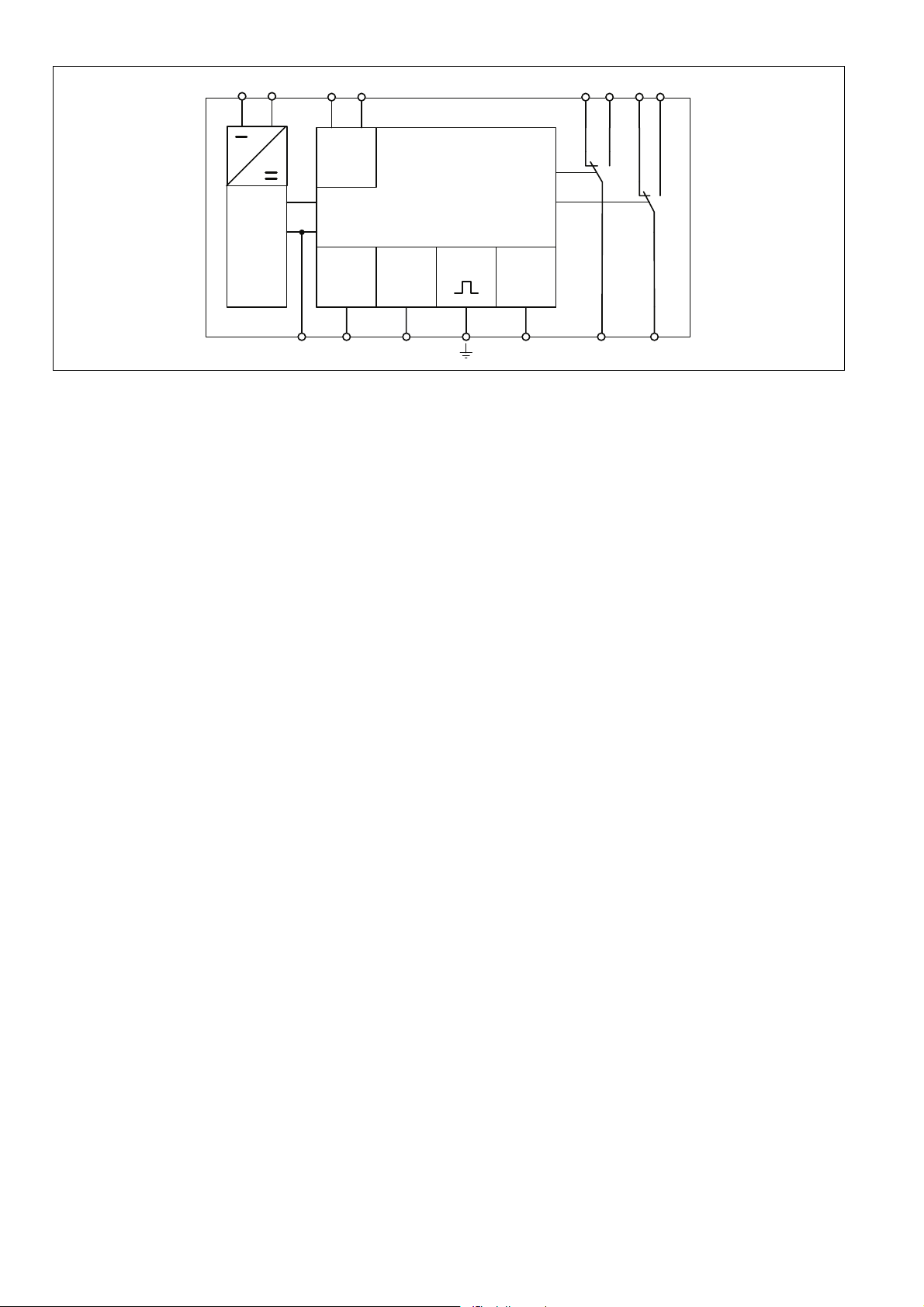
Blockschaltbild Block diagram Schéma de principe
A1 A2
~
-
+
Power
Y1 Y2 Y3
Funktionsbeschreibung
1181046155
Der Isolationswächter verhindert das Entstehen
gefahrbringender Isolationsfehler in galvanisch
getrennten Spannungsnetzen. Dazu werden
die Isolationswiderstände zwischen den Phasen des Netzes und der Betriebserde gemessen. Das Messprinzip erkennt symmetrische
und unsymmetrische Isolationsfehler.
Relaisausgänge (K1 und K2)
K1 und K2 arbeiten nach dem Ruhestromprinzip. Dabei sind im Grundzustand die Hilfskontakte 11-14 und 21-24 geschlossen und die
Hilfskontakte 11-12 und 21-22 geöffnet. Das
Ruhestromprinzip ist die Default-Einstellung,
diese Einstellung ist im Menü änderbar.
Ansprechwiderstand
Wenn der Isolationswiderstand den eingestellten Ansprechwiderstand R
den Messkreise unterschreitet (R
leuchtet die LED "Out 1" oder "Out 2" und die
Relaiskontakte fallen ab.
` Ansprechwiderstand Ran1:
Die Hilfskontakte 11-14 öffnen und die Hilfskontakte 11-12 schließen. (Ruhestromprinzip).
` Ansprechwiderstand Ran2:
Die Hilfskontakte 21-24 öffnen und die Hilfskontakte 21-22 schließen. (Ruhestromprinzip).
Überwachung der Betriebserde
Wenn die Verbindung zwischen der Betriebserde und der Klemme FE unterbrochen wird,
dann schließen die Kontakte 11-12 und 21-22
(Ruhestromprinzip).
in einem der bei-
an
< R
E
an
),
B1 B2
U
M
K1
K2
G
Reset Test
Feedback
Earth
FE
Function description
The insulation monitor prevents hazardous insulation faults in galvanically separated systems. The insulation resistances are measured
between the network phases and the operating
earth. The measuring principle detects symmetrical and asymmetrical insulation faults.
Relay outputs (K1 and K2)
K1 and K2 operate in normally energised mode.
In their default state, auxiliary contacts 11-14
and 21-24 are closed and auxiliary contacts 1112 and 21-22 are open. Normally energised
mode is the default setting; this setting can be
changed via the menu.
Response resistance
If the insulation resistance falls below the set
response resistance R
measuring circuits (R
or "Out 2" will light and the relay contacts will
in either of the two
an
< R
), the LED "Out 1"
E
an
de-energise.
` Response resistance Ran1:
Auxiliary contacts 11-14 will open and auxiliary contacts 11-12 will close (normally energised mode).
` Response resistance Ran2:
Auxiliary contacts 21-24 will open and auxiliary contacts 21-22 will close (normally energised mode).
Monitoring the operating earth
If the connection between the operating earth
and the FE terminal is broken, contacts 11-12
and 21-22 will close (normally energised mode).
12 14 22 24
11 21
Description du fonctionnement
Le contrôleur d'isolement permet d'éviter les
dangers liés à un défaut d'isolement dans des
réseaux isolés galvaniquement. À cet effet, les
résistances d'isolement entre les phases du réseau et la terre sont mesurées. Le principe de
mesure détecte les défauts d'isolement symétriques et asymétriques.
Sorties relais (K1 et K2)
K1 et K2 fonctionnent suivant le principe de
l'action positive. À l'état initial, les contacts
d'information 11-14 et 21-24 sont fermés et les
contacts d'information 11-12 et 21-22 sont
ouverts. Le principe de l'action positive est le
réglage par défaut. Ce réglage peut être modifié dans le menu.
Impédance
Si la résistance d'isolement est inférieure (R
) à l'impédance paramétrée R
R
an
des deux circuits de mesure, la LED « Out 1 »
dans l'un
an
<
E
ou « Out 2 » s'allume et les contacts relais retombent.
` Impédance Ran1 :
Les contacts d'information 11-14 s'ouvrent
et les contacts d'information 11-12 se ferment (principe de l'action positive).
` Impédance Ran2 :
Les contacts d'information 21-24 s'ouvrent
et les contacts d'information 21-22 se ferment (principe de l'action positive).
Surveillance de la terre
Si la liaison entre la terre et la borne FE est interrompue, les contacts 11-12 et 21-22 se ferment (principe de l'action positive).
- 2 -
Page 3
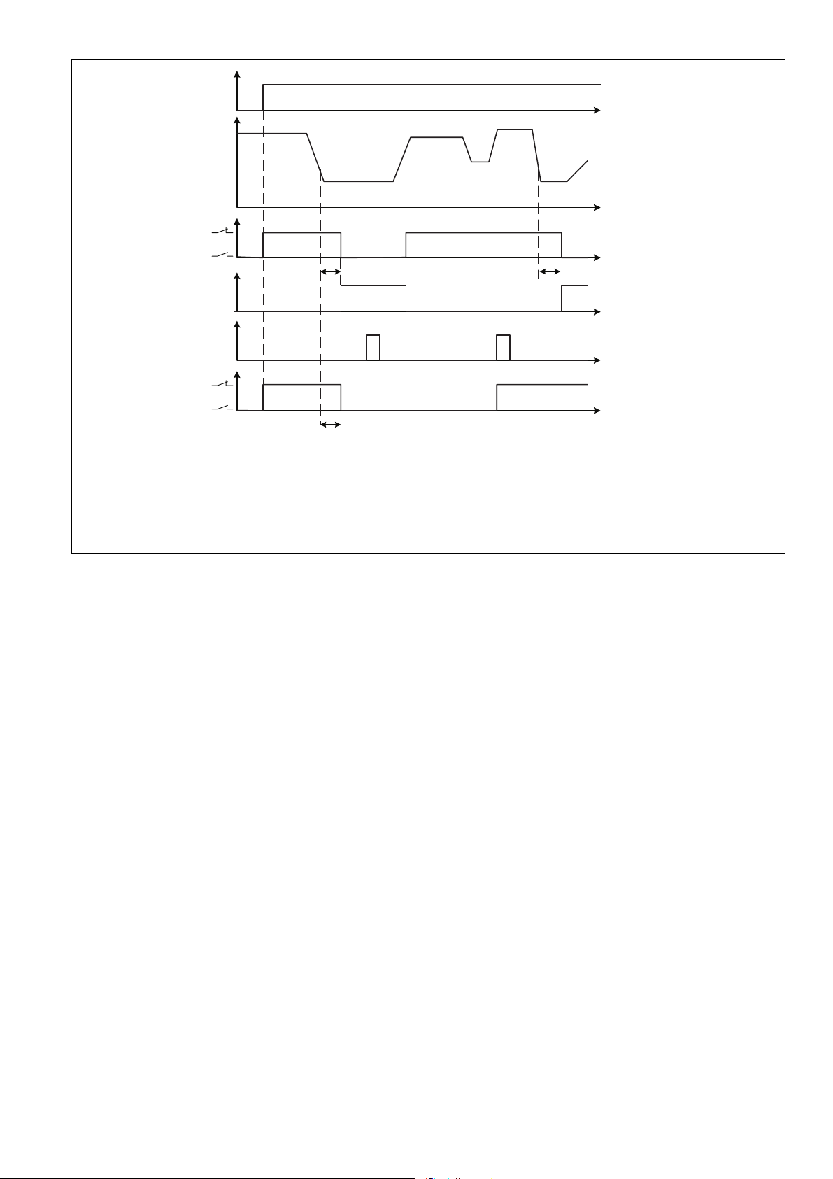
Funktionsdiagramm Timing diagram Diagramme fonctionnel
UB
R
E
R
ab
R
an
-
11
14
-
21 24
tr
tr
Reset
11
21
LED
-
14
-
24
1
0
1
0
UB = Versorgungsspannung/Supply voltage/Tension d'alimentation
R
= Ansprechwert/Response value/Seuil de déclenchement
an
R
= Rücksetzwert/Release value/Valeur de réarment
ab
= Isolationswiderstand/Insulation resistance/Résistance de'isolement
R
E
t
Hysteresis
t
Auto reset
tr
t
t
t
Manual reset
t
Montage
1042929547
` Montieren Sie das Gerät in einen Schalt-
schrank mit einer Schutzart von mindestens
IP54.
` Befestigen Sie das Gerät mit Hilfe des Rast-
elements auf der Rückseite auf einer Montageschiene.
` Sichern Sie das Gerät auf einer senkrechten
Montageschiene (35 mm) durch ein Halteelement (z. B. Endhalter oder Endwinkel).
` Vor dem Abheben von der Montageschiene
Gerät nach oben oder unten schieben.
Inbetriebnahme
1182220427
Beachten Sie bei der Inbetriebnahme:
` Die Ausgangskontakte 11-12-14 und 21-22-
24 sind Hilfskontakte (z. B. für Anzeige oder
Schützansteuerung)
` Gerät nur im spannungslosen Zustand ver-
drahten!
` Leitungsmaterial aus Kupferdraht verwen-
den.
` Vor die Ausgangskontakte eine Sicherung (s.
techn. Daten) schalten, um das Verschweißen der Kontakte zu verhindern.
` Auf eine sorgfältige Leitungsverlegung ach-
ten, da eine Unterbrechung im Messkreis
zum Ausfall der Gerätefunktion führt.
` Auf eine ausreichende Absicherung der An-
schlussleitungen an den Klemmen B1 und
B2 achten.
` An galvanisch zusammenhängenden Span-
nungsnetzen nur ein Isolationsüberwachungsgerät anschließen.
` Zur Kontrolle des richtigen Anschlusses des
Gerätes eine Funktionsprüfung mit echtem
Erdschluss (widerstand) durchführen.
` Angaben im Abschnitt „Technische Daten“
unbedingt einhalten.
Installation
The unit should be installed in a control cab-
`
inet with a protection type of at least IP54.
` Use the notch on the rear of the unit to attach
it to a mounting rail.
` Ensure the unit is mounted securely on a ver-
tical mounting rail (35 mm) by using a fixing
element (e.g. retaining bracket or an end angle).
` Push the unit upwards or downwards before
lifting it from the mounting rail.
Commissioning
When commissioning, please note the following:
` Output contacts 11-12-14 and 21-22-24 are
auxiliary contacts (e.g. for a display or contactor control)
` Only wire the unit when the supply voltage is
switched off!
` Use copper wiring.
` To prevent contact welding, a fuse should be
connected before the output contacts (see
technical details).
` Ensure that the cables are laid carefully, be-
cause an open circuit in the measuring circuit
will cause the unit to malfunction.
` Ensure there is adequate fuse protection on
the connection cables at terminals B1 and
B2.
` Only one insulation monitor should be con-
nected to galvanically connected systems.
` A function test involving a real earth fault (re-
sistance) must be carried out in order to
check that the unit is properly connected.
` Information given in the “Technical details”
must be followed.
Montage
Installez l'appareil dans une armoire ayant un
`
indice de protection d'au moins IP54.
` Montez l'appareil sur un rail de montage à
l'aide du système de fixation situé au dos de
l'appareil.
` Fixez l'appareil sur un rail de montage verti-
cal (35 mm) à l'aide d'un élément de retenue
(par exemple, une console ou une équerre
terminale).
` Avant de retirer l'appareil du rail de montage,
poussez l'appareil ve rs le haut ou vers le bas.
Mise en service
Veuillez tenir compte des points suivants lors
de la mise en service :
` Les contacts de sortie 11-12-14 et 21-22-24
sont des contacts d'information (exemple :
pour l'affichage ou la commande des contacteurs)
` Ne raccorder l'appareil que lorsqu'il est hors
tension !
` Utiliser uniquement des fils de câblage en
cuivre.
` Protection des contacts de sortie par des fu-
sibles (voir les caractéristiques techniques)
pour éviter leur soudage.
` Poser attentivement les câbles car une inter-
ruption dans le circuit de mesure entraîne
une panne du fonctionnement de l'appareil.
` Prévoir une protection adéquate sur le circuit
relié aux bornes B1 et B2.
` Ne brancher qu'un seul relais de surveillance
d'isolement aux réseaux reliés galvaniquement entre eux.
` Pour vérifier qu'un appareil est correctement
raccordé, procéder à un contrôle du fonctionnement avec une véritable mise à la terre
(résistance).
` Respecter impérativement les données indi-
quées dans la partie « Caractéristiques techniques ».
- 3 -
Page 4
Isolationwächter konfigurieren
1075320075
Die Menüeinstellungen werden am Display des
Geräts mit Hilfe eines Drehknopfs vorgenommen. Sie haben die Möglichkeit, Einstellungen
am Drehknopf von Hand oder mit einem
Schraubendreher vorzunehmen. Bei Einstellungen mit einem Schraubendreher kann der
Drehknopf im Gerät verbleiben.
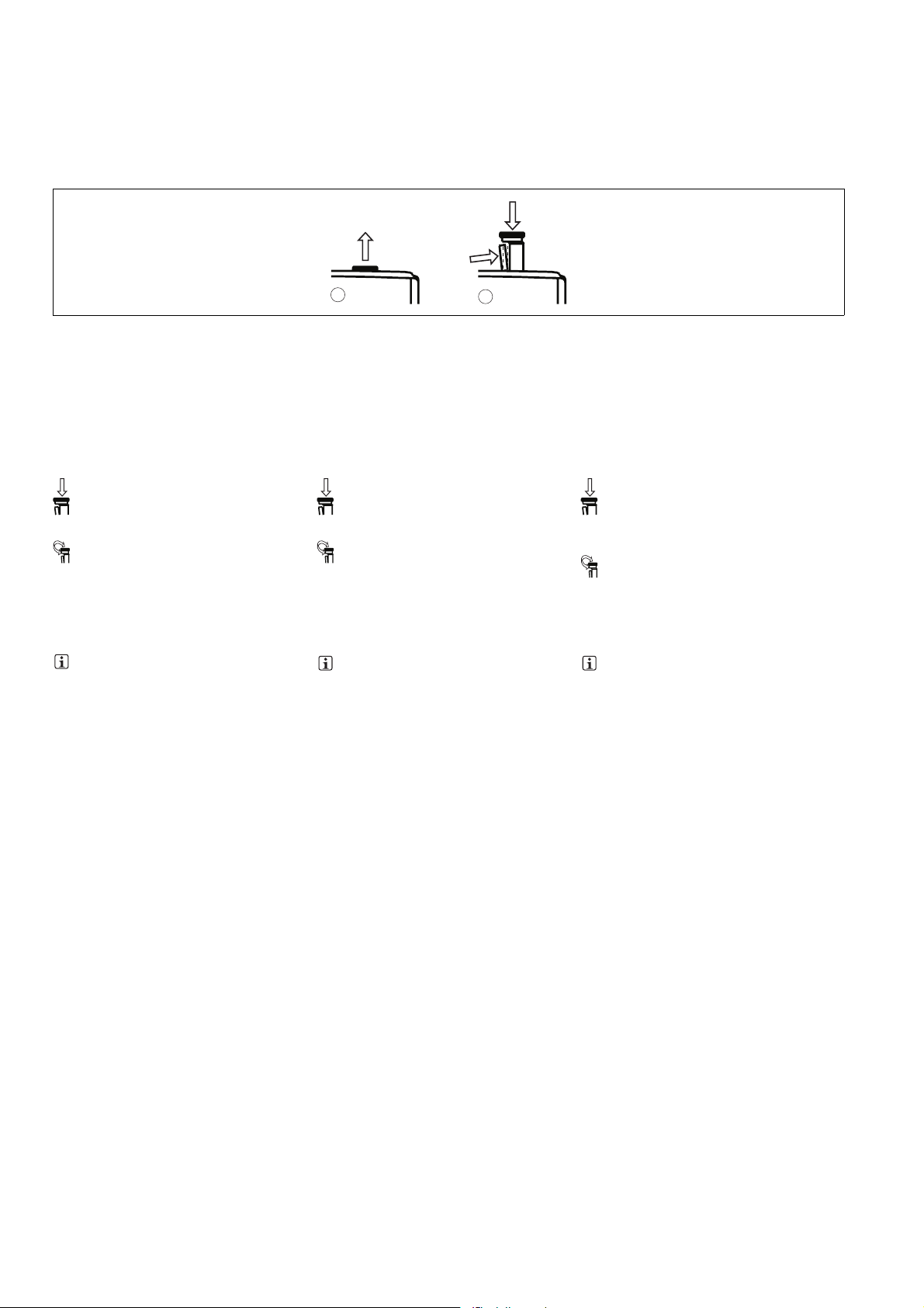
` Drehknopf herausziehen und zurückschie-
ben
Configuring the insulation monitor
The menu settings are made on the unit's display via a rotary knob. You have the option to
make the settings on the knob by hand or with
a screwdriver. If you make the settings with a
screwdriver, the knob can remain within the
unit.
` Pull out and retract the knob ` Retirer le bouton rotatif et le reculer
2.
1.
Configurer le contrôleur d'isolement
Les paramétrages des menus sont effectués
sur l'écran de l'appareil à l'aide d'un bouton rotatif. Vous pouvez effectuer des modifications
manuellement à l'aide du bouton rotatif ou à
l'aide d'un tournevis. Si les réglages sont effectués à l'aide d'un tournevis, le bouton rotatif
peut rester dans l'appareil.
1042955147
Den Drehknopf:
` (A) herausziehen, bis dieser einrastet
` (B) entriegeln und in das Gerät zurückschie-
ben:
– Riegel an der Seite des Drehknopfs (1) zur
Mitte des Drehknopfs hin drücken. Drehknopf ist entriegelt
– Drehknopf nach unten drücken (2) und
gleichzeitig Riegel gedrückt halten
` Einstellungen vornehmen
1043019915
Drücken
` Anwahl/Einstellung bestätigen
` In Menü wechseln
1155335435
` Parameter/Zahlenwert einstellen
1042984075
Drehen
` Menüpunkt wählen
` Parameter/Zahlenwert mit folgender
Drehgeschwindigkeit einstellen:
Langsam: Einerstellen
Schnell: Zehnerstellen
Sehr schnell: Hunderterstellen
1042949259
INFO
Wird nach einer Aktion im Menü innerhalb
von 30 s kein Wert eingestellt oder verändert, wechselt die Anzeige zurück zur Standardanzeige. Die aktuelle Einstellung bleibt
unverändert.
A
B
The rotary knob:
` (A) should be pulled out until it clicks into po-
sition
` (B) then released and retracted back into the
unit:
– Press the latch on the side of the rotary
knob (1) towards the centre of the knob.
This releases the rotary knob.
– Press the knob downwards (2) while keep-
ing the latch held down.
` Making the settings
Press
` Confirm selection/setting
` Switch to menu
` Set the parameter/numeric value
Rotate
` Select menu option
` Set the parameter/numeric value with
the following rotational speed:
Slow: Unit's digits
Fast: Ten's digits
Very fast: Hundred's digits
INFORMATION
Once an action has been taken in the
menu, the display switches back to the default display if a value is not set or modified
within 30 s. The current setting remains unchanged.
Le bouton rotatif :
` (A) doit être retiré jusqu'à l'enclenchement
` (B) doit être déverrouillé et repoussé dans
l'appareil :
– Pousser le verrou sur le côté du bouton ro-
tatif (1) au centre du bouton rotatif. Le bouton rotatif est déverrouillé
– Pousser le bouton rotatif vers le bas (2) et
maintenir parallèlement le verrou enfoncé
` Effectuer les réglages
Appuyer
` confirmer la sélection / le réglage
` Passer dans le menu
` Configurer le paramètre / la valeur numéri-
que
Tourner
` Sélectionner le point de menu
` Configurer le paramètre / la valeur numé-
rique avec la vitesse suivante :
lente : unités
rapide : dizaines
très rapide : centaines
INFORMATION
Après une action dans le menu, si aucune
valeur n'est configurée ou modifiée en l'espace de 30 s, l'afficheur retourne à l'affichage standard. Le réglage actuel reste
inchangé.
- 4 -
Page 5

` Menüeinstellungen ` Menu settings ` Paramétrages des menus
` Parameter ablesen und einstellen
1183013387
Für den Betrieb sind Einstellungen im Menü des
Geräts notwendig.
` Parameter einstellen Menü "Settings" ` Set parameters, "Settings" menu ` Réglage des paramètres, menu « Réglages »
Default Wert/
Default value/
Valeur par défaut
Ran 1
50 kΩ
Ran 2
100 kΩ
tStart
0.0 s
tr
0.0 s
Reset
auto
Parameter einstellbar von ... bis/
Parameters selectable from ... to/
Paramètres configurables de ... à
-> Ran 1
10 kΩ
-> Ran 2
10 kΩ
-> tStart
0.0 s
-> tr
0.0 s
-> Reset
auto
` Read and set parameters
Some settings are required in the unit's menu in
order to operate the unit.
-> Ran 1
200 kΩ
-> Ran 2
200 kΩ
-> tStart
30.0 s
-> tr
30.0 s
-> Reset
manual
` Lire et configurer les paramètres
Des réglages sont nécessaires au fonctionnement de l'appareil.
Unverändert verlassen/
Leave unchanged/
Laisser inchangé
-> Ran 1
Escape
-> Ran 2
Escape
-> tStart
Escape
-> tr
Escape
-> Reset
Escape
Settings
Escape
1181276555
` Ansprechwert (Ran1)
Ansprechwert des Isolationswiderstands.
Schaltet die Hilfskontakte 11-12-14.
` Ansprechwert (Ran2)
Ansprechwert des Isolationswiderstands.
Schaltet die Hilfskontakte 21-22-24
` Startunterdrückung (t
Nach Einschalten der Versorgungsspannung
wird die Messung für die eingestellte Zeit
unterdrückt.
t
start
` Reaktionszeit (t
Unterschreitet der Isolationswiderstand R
)
r
den eingestellten Ansprechwert Ran1 oder
Ran2, dann schalteten die Hilfskontakte
nach einer eingestellten Reaktionszeit (t
und die LED "Out 1" oder "Out 2" leuchtet.
` Rücksetzmodus (Reset)
1181231627
` Reset auto
Das Gerät startet selbst, sobald sich der Isolationswiderstand wieder auf den Rücksetzwert vergrößert hat (R
` Reset manual
Wenn sich der Isolationswiderstand wieder
auf den Rücksetzwert vergrößert hat (R
), starten Sie den Isolationswächter
≥R
ab
durch:
– durch Betätigen eines Tasters an den
Klemmen Y1 und Y2
start
E
≥R
)
ab).
` Response value (Ran1)
Response value of insulation resistance.
Switches the auxiliary contacts 11-12-14.
` Response value (Ran2)
Response value of insulation resistance.
Switches the auxiliary contacts 21-22-24
` Start suppression (t
After the supply voltage is switched on,
measurement is suppressed for the preset
time t
start
` Reaction time (t
,
If the insulation resistance R
E
set response value Ran1 or Ran2, the auxiliary contacts will switch over after a preset
) um
r
reaction time (t
2" will light.
` Reset mode
` Reset auto
The unit starts automatically as soon as the
insulation resistance has increased back to
the release value ((R
` Reset manual
Once the insulation resistance has increased
E
back to the release value (R
the insulation monitor by:
– pressing a button at terminals Y1 and Y2
)
start
.
)
r
) and the LED "Out 1" or "Out
r
E
≥R
off).
falls below the
E
.
≥R
E
), restart
off
` Seuil de déclenchement (Ran1)
Seuil de déclenchement de la résistance
d'isolement. Commute les contacts d'information 11-12-14.
` Seuil de déclenchement (Ran2)
Seuil de déclenchement de la résistance
d'isolement. Commute les contacts d'information 21-22-24
` Suppression au démarrage (t
Après la mise sous tension, la mesure de
l'heure réglée t
` Temps de réponse (t
Si la résistance d'isolement R
au seuil de déclenchement réglé Ran1 ou
est supprimée.
start
)
r
)
start
est inférieure
E
Ran2, les contacts d'information commutent
vers le temps de réponse réglé (t
« Out 1 » ou « Out 2 » s'allume.
) et la LED
r
` Mode de réarmement (reset)
` Réarmement automatique
Dès que la résistance d'isolement a de nouveau atteint la valeur de réarmement (R
≥R
ab), le relais se réarme automatiquement.
` Réarmement manuel
Si la résistance d'isolement a de nouveau atteint la valeur de réarmement (R
mez le contrôleur d'isolement :
– en actionnant un bouton-poussoir sur les
bornes Y1 et Y2
≥Rab), réar-
E
E
- 5 -
Page 6

` Parameter einstellen Menü "Advanced Set-
tings"
Default Wert/
Default value/
Valeur par défaut
Hyst.
15 % Ran
Ce max.
0.5 μF
Rel. K1
norm. on
Rel. K2
norm. on
Load
Default
1181290635
` Schalthysterese (Hyst.)
Wert für automatisches Zurücksetzen des
Fehlerzustands (siehe Funktionsdiagramm)
Parameter einstellbar von ... bis/
Parameters selectable from ... to/
Paramètres configurables de ... à
-> Hyst.
0 % Ran
-> Ce max.
1.0 μF
-> Rel. K1
norm. on
-> Rel. K2
norm. on
-> Load
Def. Esc
` Netzableitkapazität (Ce max.)
Kapazität zwischen IT-Netz und Betriebserde
` Schaltrichtung (Rel. K1)
Arbeits- oder Ruhestromprinzip für Hilfskontakt K1
` Schaltrichtung (Rel. K2)
Arbeits- oder Ruhestromprinzip für Hilfskontakt K2
` Defaultwerte laden
(Load Default)
Zurücksetzen aller Parameter auf Werkseinstellungen
` Parameter ablesen "Menü Info"
1182332427
` Betriebsstunden (t
Betriebsstundenzähler
Operate
)
` Ansprechwert Ran 1 oder Ran 2 unterschrit-
Alarm
)
ten (t
` Schaltspiele Relais K1 (K1 cycle)
` Schaltspiele Relais K2 (K2 cycle)
` Software Version (Software)
` Set parameters, "Advanced Settings" menu ` Réglage des paramètres, menu « Réglages
avancés »
Unverändert verlassen/
Leave unchanged/
Laisser inchangé
-> Hyst.
50 % Ran
-> Ce max.
20.0 μF
-> Rel. K1
norm. off
-> Rel. K2
norm. off
-> Load
Def. yes?
` Switching hysteresis (Hyst.)
Value for automatic reset of the fault status
(see timing diagram)
` Leakage capacitance (Ce max.)
Capacitance between IT system and operating earth
` Switching direction (Rel. K1)
Normally energised or de-energised mode
for auxiliary contact K1
` Switching direction (Rel. K2)
Normally energised or de-energised mode
for auxiliary contact K2
` Load default values
(Load Default)
Reset all parameters to the factory default
settings
` Read "Menu Info" parameter
` Operating hours (t
Operating hours counter
Operate
)
` Value below response value Ran 1 or Ran 2
)
(t
Alarm
` Cycles for relay K1 (K1 cycle)
` Cycles for relay K2 (K2 cycle)
` Software version (Software)
-> Hyst.
Escape
-> Ce max.
Escape
-> Rel. K1
Escape
-> Rel. K2
Escape
-> Default
Loaded
Adv. Set.
Escape
` Hystérésis de commutation (Hyst.)
Valeur pour le réarmement automatique de
l'état d'erreur (voir le diagramme fonctionnel)
` Capacité d'évacuation d'un réseau (Ce max.)
Capacité entre un réseau IT et la mise à la
terre
` Sens de commutation (Rel. K1)
Mode excitation ou mode retombée pour le
contact d'information K1
` Sens de commutation (Rel. K2)
Mode excitation ou mode retombée pour le
contact d'information K2
` Charger les valeurs par défaut
(Load Default)
Réinitialisation de tous les paramètres sur les
réglages d'usine
` Relever le paramètre « Menu info »
` Durée de fonctionnement (t
Compteur d'heures de fonctionnement
Operate
)
` Seuil de déclenchement Ran 1 ou Ran 2 infé-
Alarm
)
rieur (t
` Manœuvres relais K1 (cycle K1)
` Manœuvres relais K2 (cycle K2)
` Version logicielle (logiciel)
- 6 -
Page 7

` Schematische Darstellung (Menü "Settings",
"Advanced Settings" und "Info"
` Schematic representation ("Settings", "Ad-
vanced Settings" and "Info" menu)
` Représentation schématique (menu
« Réglages », « Réglages avancés » et
« Information »)
Re
100 k
Ω
Settings
Advanced
Settings
Ran 1
50 k
Ran 2
100 k
tStart
0.0 s
tr
0.0 s
Reset
auto
Settings
Escape
Hyst.
15% Ran
Ce max.
0.5 µF
Ω
Ω
-> Ran 1
10 k
Ω
-> Ran 2
10 k
Ω
->tStart
0.0 s
-> tr
0.0 s
-> Reset
auto
-> Hyst.
0 % Ran
-> Ce max.
0.5 µF
-> Ran 1
Escape
-> Ran 2
Escape
->tStart
Escape
-> tr
Escape
-> Reset
Escape
-> Hyst.
Escape
-> Ce max.
Escape
Info
Menue
Escape
Rel. K1
norm on
Rel. K2
norm on
Load
Default
Adv.Set.
Escape
tOperate
Info
Escape
-> Rel. K1
norm on
-> Rel. K2
norm on
-> Load
Def. yes?
-> Rel. K1
norm off
-> Rel. K2
norm off
...
Escape
-> Rel. K1
Escape
-> Rel. K2
Escape
-> Load
Def. Esc
- 7 -
Page 8

Chipkarte verwenden
1043129739
Auf der Chipkarte können die auf einem Gerät
eingestellten Parameter gespeichert werden.
Die Daten werden zusammen mit einer Gerätekennung abgelegt. Wir empfehlen, das Gerät
immer mit Chipkarte zu betreiben.
` Wurden bei einem Gerät die Parameter
durch einen Fehler verändert, können sie mit
einer Sicherungskopie auf Chipkarte wiederhergestellt werden.
` Muss ein Gerät gewartet oder ausgetauscht
werden, können Sie mit der Chipkarte diese
Geräteparameter auf ein anderes Gerät übertragen.
INFO
Betreiben Sie das Gerät ohne Chipkarte,
leuchtet die LED „Fault“ und es erscheint
einmalig die Meldung Insert SIM Card.
Wenn Sie Parameter verändern, erscheint
erneut die Meldung .
Wenn sich die Chipkarte im Gerät befindet,
` wird die Chipkarte auf Gerätekennung und
auf identische Daten geprüft.
` werden während des Betriebs Gerätepara-
meter automatisch auf die Chipkarte gesichert. Auf der Chipkarte befindet sich somit
immer eine Kopie der aktuellen internen Daten des Geräts. Ausnahme: wenn Sie Write
SIM? no wählen.
Use chip card
The parameters that are set on a unit can be
stored on the chip card. The data is stored
along with a device identifier. We recommend
that you always operate the unit with a chip
card.
` If the parameters on a device have been
changed due to an error, they can be restored using the backup copy on the chip
card.
` If a unit requires maintenance or needs to be
exchanged, the chip card can be used to
download the parameters to another unit.
INFORMATION
If you operate the unit without a chip card,
the "Fault" LED will light and the following
message will appear once only: Insert SIM
Card. If you change the parameters, the
message will reappear.
When the chip card is inside the unit:
` The chip card is checked to verify the device
identifier and ensure that the data is identical.
` Unit parameters are automatically saved to
the chip card during operation. As a result,
the chip card always contains a copy of the
unit's current internal data. Exception: If you
select Write SIM? no.
Utiliser la carte à puce
Les paramètres configurés sur un appareil peuvent être enregistrés sur la carte à puce. Les
données sont enregistrées avec une reconnaissance d'appareil. Nous recommandons de tou-
jours utiliser l'appareil avec la carte à puce.
` Si les paramètres configurés sur un appareil
ont été modifiés du fait d'une erreur, ils peuvent être restaurés à l'aide d'une copie de
sauvegarde sur la carte à puce.
` Si un appareil doit être réparé ou remplacé,
vous pouvez utiliser la carte à puce pour
transférer ces paramètres sur un autre appareil.
INFORMATION
Si vous utilisez l'appareil sans carte à puce,
la LED « Fault » s'allume et le message In-
sert SIM Card apparaît une première fois.
Si vous modifiez des paramètres, le message apparaît à nouveau.
Si la carte à puce se trouve dans l'appareil,
` la reconnaissance de l'appareil et la similitu-
de des données de la carte à puce sont contrôlées.
` les paramètres de l'appareil sont enregistrés
automatiquement sur la carte à puce durant
le fonctionnement. Ainsi, une copie des données internes actuelles de l'appareil se trouve toujours sur la carte à puce. Exception : si
vous sélectionnez l'option Write SIM? no.
` Chipkarte einsetzen
1043139467
WICHTIG
Die Kontaktierung der Chipkarte ist nur gewährleistet, wenn die Kontaktfläche sauber
und unbeschädigt ist. Schützen Sie deshalb die Kontaktfläche der Chipkarte vor
` Verunreinigung
` Berührung
` mechanischer Einwirkung, wie z. B. Krat-
zern.
WICHTIG
Schalten Sie das Produkt vor dem Einset-
zen oder Wechseln der Chipkarte aus.
Achten Sie darauf, dass sich die Chipkarte
nicht verkantet, wenn Sie die Chipkarte in den
Chipkartenschacht schieben.
` Insert chip card
NOTICE
The chip card contact is only guaranteed if
the contact surface is clean and undamaged. For this reason please protect the
chip card's contact surface from
` Contamination
` Contact
` Mechanical impact, such as scratches.
NOTICE
Switch off the product before inserting or
exchanging the chip card.
Make sure that you do not bend the chip card
as you insert it into the chip card slot.
` Insérer la carte à puce
IMPORTANT
Le bon contact de la carte à puce est uniquement garanti si les surfaces de contact
sont propres et intactes. Il convient donc
de protéger les surfaces de contact de la
carte à puce contre
` les impuretés
` les contacts
` les actions mécaniques, telles que, par
exemple, les rayures.
IMPORTANT
Éteignez le produit avant d'insérer ou de
remplacer la carte à puce.
Faites attention à ce que la carte à puce ne se
coince pas lorsque vous l'insérez dans la fente.
- 8 -
Page 9

` Daten auf Chipkarte schreiben
1043149963
Setzen sie eine Chipkarte ein, die noch nicht
von einem PMD s20 beschrieben wurde, haben
Sie die Option:
` Write data to chip card
If you are inserting a chip card which has not
yet been written by a PMD s20, you have the
option to:
` Inscrire des données sur la carte à puce
Si vous insérez une carte à puce qui n'a pas encore été inscrite par un PMD s20, vous disposez des options suivantes :
` Schreiben der Daten auf Chipkarte zulassen ` Allow data to be written to chip card ` Autoriser l'inscription de données sur la carte
à puce
Chipkarte einsetzen/
Insert chip card/
Insérer la carte à puce
Insert
SIM Card
Write
SIM? no
` Schreiben der Daten auf Chipkarte nicht zu-
lassen
Chipkarte einsetzen/
Insert chip card/
Insérer la carte à puce
Insert
SIM Card
` Daten von Chipkarte lesen
1043163659
Setzen sie eine Chipkarte ein, die schon von einem PMD s20 beschrieben wurde, haben Sie
die Option:
Write
SIM? no
1. -> select 2. Daten werden auf Chipkarte geschrieben/
Write
SIM? yes
Data will be written to the chip card/
Inscription des données sur la carte à puce
Re
….
` Do not allow data to be written to chip card ` Empêcher l'inscription de données sur la
carte à puce
1. Daten werden nicht auf Chipkarte geschrieben/
` Read data from chip card
If you are inserting a chip card which has already been written by a PMD s20, you have the
option to:
Data will not be written to the chip card/
Les données ne sont pas inscrites sur la carte à puce
Insert
SIM Card
` Lire des données sur la carte à puce
Si vous insérez une carte à puce qui a déjà été
inscrite par un PMD s20, vous disposez des
options suivantes :
` Lesen der Daten von Chipkarte zulassen ` Allow data to be read from chip card ` Autoriser la lecture des données sur la carte
à puce
Chipkarte einsetzen/
Insert chip card/
Insérer la carte à
puce
Re
….
Daten der Chipkarte zu Gerät
unterschiedlich/
Data on chip card differs from
that on unit/
Données de la carte à puce différentes de l'appareil
Load
SIM? no
1. -> select 2. Daten werden in das Gerät gelesen/
Load
SIM? yes
Data is read into the unit/
Les données sont lues dans l'appareil
Re
….
` Lesen der Daten von Chipkarte nicht zulas-
sen
Chipkarte einsetzen/
Insert chip card/
Insérer la carte à puce
Re
….
` Geräteparameter übertragen
1043176971
Sie können Geräteparameter mit Hilfe der Chipkarte von einem Gerät auf ein anderes Gerät
übertragen.
Gehen Sie wie folgt vor:
Daten der Chipkarte zu Gerät unterschiedlich/
Data on chip card differs from that on
unit/
Données de la carte à puce différentes
de l'appareil
Load
SIM? no
` Chipkarte mit den Daten des Geräts (1) ent-
fernen.
` Chipkarte in Gerät (2) einsetzen.
` Meldung Load SIM yes? bestätigen.
Daten werden übertragen.
` Do not allow data to be read from chip card ` Empêcher la lecture des données sur la carte
à puce
1. Daten werden nicht in das Gerät gelesen, Daten werden auf
` Transfer device parameters
You can use the chip card to transfer device
parameters from one unit to another.
Proceed as follows:
` Remove the chip card containing the data
from the unit (1).
` Insert chip card into unit (2).
` Confirm the message Load SIM yes?.
The data will be transferred.
Chipkarte geschrieben/
Data will not be read into unit, data will be written to chip
card/
Les données ne sont pas lues dans l'appareil, les données
sont inscrites sur la carte à puce
Re
….
` Transférer les paramètres de l'appareil
Vous pouvez utiliser la carte à puce pour transférer des paramètres d'un appareil à un autre.
Procédez comme suit :
` Retirer la carte à puce avec les données de
l'appareil (1).
` Insérer la carte à puce dans l'appareil (2).
` Confirmer le message Load SIM yes?.
Les données sont transférées.
- 9 -
Page 10

Betriebsbereitschaft herstellen
1181317515
Hier wird der prinzipielle Ablauf der Parametrierung beschrieben. Das Vorgehen wird auf den
folgenden Seiten durch konkrete Beispiele beschrieben.
Parametrierung:
` Stellen Sie den Ansprechwert R
` Das Gerät hat eine einstellbare Ansprechto-
ein.
an
leranz (Hyst. Ran). Diese kann bei der Einstellung berücksichtigt werden, falls ein nach
Norm geforderter Wert nicht unterschritten
werden soll.
` Optionale Einstellungen:
– Startunterdrückungszeit t
Start des Gerätes wird während der eingestellten Zeit der Ansprechwert Ran nicht
ausgewertet.
– Reaktionszeit t
stellen, dass das Gerät auf kurze Über-
: Reaktionszeit tr so ein-
r
oder Unterschreitung des Isolationswiderstands nicht reagiert.
– manueller oder automatischer Reset
` Vorgehensweise (Beispiel)
1182248331
In diesem Kapitel wird die Konfiguration des
Isolationswächters am Display anhand von
zwei Beispielen gezeigt.
: Nach einem
start
` Beispiel 1:
Ran1: 80 kOhm
Preparing for operation
This section describes the main procedure for
setting the parameters. In the following pages,
the procedure is described using real examples.
Setting the parameters:
` Set the response value R
` The unit has a selectable response tolerance
.
an
(Hyst. Ran). This can be considered when
making settings, should it be necessary to
ensure that a value does not fall below a level
required by the standard.
` Optional settings:
– Start-up suppression time t
unit is started, the response value Ran is
not evaluated during the preset time.
– Reaction time t
that the unit will not react if the insulation
: Set the reaction time tr so
r
resistance briefly exceeds or falls below
the required value.
– Manual or automatic reset
: When the
start
` Procedure (example)
This section uses two examples to illustrate
how the insulation monitor is configured on the
display.
` Example 1:
Ran1: 80 kOhm
Main Menu Submenu 1
Préparation à la mise en service
Le processus principal du paramétrage est décrit ici. La procédure est décrite sur les pages
suivantes à l'aide d'exemples concrets.
Paramétrage :
` Réglez le seuil de déclenchement R
` L'appareil dispose d'une tolérance de dé-
.
an
clenchement réglable (Hyst. Ran). Il est possible de tenir compte de cette dernière lors
du réglable au cas où une valeur exigée par
une norme ne doit pas être inférieure.
` Réglages optionnels :
– Temps de suppression au démarrage t
: Suite au démarrage de l'appareil, le seuil
de déclenchement Ran n'est pas analysé
pendant la durée programmée.
– Temps de réponse t
réponse t
ne réagisse pas aux valeurs inférieures ou
de manière à ce que l'appareil
r
: Régler le temps de
r
supérieures de courte durée de la résistance d'isolement.
– Réarmement manuel ou automatique
` Procédure (exemple)
Ce chapitre présente la configuration du contrôleur d'isolement sur écran, illustrée par deux
exemples.
start
` Exemple 1 :
Ran1 : 80 kOhm
1182312331
` Beispiel 2:
Hysterese: 10%
Re
100 k
Re
100 k
` Example 2:
Hysteresis: 10%
Ω
Ω
Settings
Main Menu Submenu 1
Settings
Advanced
Settings
-> Ran 1
20 kΩ
-> Ran 1
80 kΩ
Ran 1
80 kΩ
15 % Ran
` Exemple 2 :
Hystérésis : 10%
Hyst.
-> Hyst.
10 %
- 10 -
Hyst.
10 %
Page 11

` Anschluss
1181332363
` Versorgungsspannung UB:
– Schließen Sie die Versorgungsspannung
UB an A1/A2 an. Die Versorgungsspannung UB kann auch dem Messkreis entnommen werden.
` Messkreis (zu überwachendes Netz):
– Zweiphasennetz:
– Schließen Sie jeweils eine Phase des zu
überwachenden Netzes an die Klemmen
B1/B2 an.
– Dreiphasennetz:
– Brücken Sie die Klemmen B1/B2 und
schließen Sie sie an den Sternpunkt des
Spannungsnetzes an.
` Schließen Sie die Ausgangskontakte ent-
sprechend der jeweiligen Anwendungsschaltung an.
` Funktionsprüfung:
– durch Betätigen eines Tasters an den
Klemmen Y1 und Y3
oder
– Drücken des Drehknopfs für mindestens 3
Sekunden
` Connection
` Supply voltage UB:
– Connect the supply voltage UB to A1/A2.
The supply voltage UB can also be taken
from the measuring circuit.
` Measuring circuit (system to be monitored):
– 2-phase system:
– Connect one phase of the monitored sys-
tem to the terminals B1/B2 respectively.
– 3-phase system:
– Link terminals B1/B2 and connect them to
the system's star point.
` Connect the output contacts in accordance
with the relevant application circuit.
` Function test:
– By pressing a button at terminals Y1 and
Y3
or
– Pressing the rotary knob for at least 3 sec-
onds
` Raccordement
` Tension d'alimentation (UB) :
– Raccordez la tension d'alimentation UB
sur A1/A2. La tension d'alimentation UB
peut aussi être prélevée du circuit de mesure.
` Circuit de mesure (réseau à surveiller) :
– Circuit biphasé :
– Reliez une phase du réseau à surveiller à
chaque borne B1/B2.
– Circuit triphasé :
– Pontez les bornes B1/B2 et reliez-les au
point neutre du réseau d'alimentation.
` Raccordez les contacts de sortie suivant le
schéma d'application correspondant.
` Contrôle du fonctionnement :
– en actionnant un bouton-poussoir sur les
bornes Y1 et Y2
ou
– en appuyant sur le bouton rotatif pendant
au moins 3 secondes
- 11 -
Page 12

Anwendung
1183820299
Bitte beachten Sie:
Schließen Sie an Klemmen ohne Klemmenbezeichnung keine Leitungen an.
Application
Please note:
Do not connect any cables to undesignated terminals.
Application
Tenez compte de ce qui suit :
Ne raccordez aucun câble aux bornes non
identifiées.
` Anwendungsschaltung AC ` Application circuit AC ` Schéma d'application AC
L1
N
1L1
1L2
PE
F1
T1
F2
A1
A2
B1
B2
e
e
R
PMD s20
R
Test
Reset
FE
Y3
Y2
Y1
11
14
21
22
12
24
E1
` Anwendungsschaltung DC ` Application circuit DC ` Schéma d'application DC
L1
N
1L1
1L2
PE
F1
T1
~
G1
=
A1
A2
B1
B2
PMD s20
FE
11
12
F2
e
e
R
R
Test
Reset
Y2
Y3
Y1
14
21
22
24
E1
- 12 -
Page 13

` Anwendungsschaltung 3 AC ` Application circuit 3 AC ` Schéma d'application 3 AC
L1
L2
L3
1L1
1L2
PE
F1
T1
F2
A1
A2
B1
B2
e
PMD s20
Test
e
R
R
Reset
FE
Y2
Y1
11
Y3
14
21
22
12
24
E1
` Anwendungsschaltung 3 AC/DC ` Application circuit 3 AC/DC ` Schéma d'application 3 AC/DC
L1
L2
L3
1L1
1L2
PE
alternativ
F1
A1
A2
B1
B2
alternative
alternatif
T1
F2
G1
PMD s20
FE
11
12
e
R
Test
Reset
Y2
Y1
Y3
14
21
22
24
E1
- 13 -
Page 14

Betrieb Operation Fonctionnement
Meldungen Messages Messages
` LED ` LED ` LED
LED leuchtet/lights/allumée Bedeutung/meaning/signification
Power grün/green/vert Versorgungsspannung liegt an, t
Supply voltage is present, t
La tension d'alimentation est fournie, t
Operate
Out 1 gelb/yellow/jaune Ansprechwert Ran 1 unterschritten, T
Value below response value Ran 1, T
Le seuil de déclenchement Ran 1 est inférieur, T
Out 2 gelb/yellow/jaune Ansprechwert Ran 2 unterschritten, T
Value below response value Ran 2, T
Le seuil de déclenchement Ran 2 est inférieur, T
zählt/
Operate
is counting/
Operate
Alarm
Alarm
Alarm
Alarm
fonctionne
zählt/
is counting/
Alarm
zählt/
is counting/
Alarm
fonctionne
fonctionne
Fault rot/red/rouge Fehlermeldung/
Error message/
Message d'erreur
` Fehlermeldungen ` Error messages ` Messages d'erreurs
Anzeige/
Display/
Affichage
Error
Feedback
LED leuchtet/
lights/
allumée
Fault
Ursache/Cause/Cause Abhilfe/Remedy/Remède
Betriebserde nicht an und FE angeschlos-
Betriebserde an und FE angeschließen/
sen/
Operating earth not connected to and FE/
Connect operating earth to and FE/
Mise à la terre non raccordée à et FE
Error Test Fault Funktionsprüfung des Gerätes fehlgeschlagen/
Unit function test failed/
Le contrôle du fonctionnement de l'appareil a
échoué
Mise à la terre raccordée à et FE
Versorgungsspannung aus- und
wieder einschalten und Funktionsprüfung wie-
derholen; gegebenenfalls Gerät tauschen./
Switch supply voltage off and on again, then re-
peat function test; Change unit if necessary./
Couper la tension d'alimentation puis la remettre
en marche et renouveler le contrôle du
fonctionnement ; remplacer l'appareil le cas
échéant
Insert
SIM Card
Fault Chipkarte nicht eingesetzt, nicht beschreibbar
oder defekt/
Chip card not inserted, not writable or defective/
Chipkarte einsetzen oder tauschen/
Insert or exchange chip card/
Insérer ou remplacer la carte à puce
La carte à puce n'est pas insérée, est protégée
en écriture ou défectueuse
- Power leuchtet nicht/
Power is not lit/
Power n'est pas allu-
Keine Versorgungsspannung/
No supply voltage/
Pas de tension d'alimentation
Versorgungsspannung prüfen/
Check supply voltage/
Contrôler la tension d'alimentation
mé
Technische Daten Technical details Caractéristiques techniques
Technische Daten Technical details Caractéristiques techniques
Elektrische Daten Electrical data Données électriques
Versorgungsspannung UBAC/DC Supply voltage UB AC/DC Tension d'alimentation UBAC/DC 24 - 240 V
Spannungstoleranz Voltage tolerance Plage de la tension d'alimentation -15 %/+10 %
Leistungsaufnahme bei U
Leistungsaufnahme bei U
Frequenzbereich AC Frequency range AC Plage de fréquences AC 50 - 60 Hz
Restwelligkeit DC Residual ripple DC Ondulation résiduelle DC 20 %
Gebrauchskategorie nach
EN 60947-4-1
Hilfskontakte: AC1 bei 240 V Auxiliary contacts: AC1 at 240 V Contacts d'information : AC1
Hilfskontakte: DC1 bei 24 V Auxiliary contacts: DC1 at 24 V Contacts d'information : DC1
Gebrauchskategorie nach
EN 60947-5-1
Hilfskontakte: AC15 bei 230 V Auxiliary contacts: AC15 at 230 V Contacts d'information : AC15
Hilfskontakte: DC13 bei 24 V (6
Schaltspiele/min)
Kontaktmaterial Contact material Matériau des contacts AgCdO + 3,0 µm Au
AC Power consumption at UB AC Consommation UBAC 5,0 VA
B
DC Power consumption at UB DC Consommation UBDC 2,5 W
B
Utilisation category in accordance
with EN 60947-4-1
Catégorie d'utilisation selon
EN 60947-4-1
pour 240 V
I
min
P
I
pour 24 V
min
P
Utilisation category in accordance
with EN 60947-5-1
Auxiliary contacts: DC13 at 24 V (6
cycles/min)
Catégorie d'utilisation selon
EN 60947-5-1
pour 230 V
Contacts d'information : DC13
pour 24 V (6 manœuvres/min)
I
I
max
max
: 0,10 A , I
: 1200 VA
max
: 0,10 A , I
: 120 W
max
: 3,0 A
: 2,0 A
max
max
: 5,0 A
: 5,0 A
- 14 -
Page 15

Elektrische Daten Electrical data Données électriques
Kontaktabsicherung, extern
= 1 kA) nach EN 60947-5-1
(I
K
External contact fuse protection
(IK = 1 kA) to EN 60947-5-1
Protection des contacts en externe
(IK = 1 kA) selon EN 60947-5-1
Schmelzsicherung flink Blow-out fuse, quick Fusible rapide
Hilfskontakte: Auxiliary contacts: Contacts d'information : 6 A
Schmelzsicherung träge Blow-out fuse, slow Fusible normal
Hilfskontakte: Auxiliary contacts: Contacts d'information : 4 A
Messkreis Measuring circuit Circuit de mesure
Netznennspannung Rated mains voltage Tension nominale 0 ... 400 V
Netznennspannung nach UL Rated mains voltage in according
Tension nominale selon UL 0 ... 300 V
with UL
Max. Fremdspannung Max. external voltage Tension externe max. 460 V
Max. Messspannug U
Max. Messstrom I
M
M
Max. measuring voltage U
Max. measuring current I
M
M
Tension max. mesurée U
Intensité max. mesurée I
M
M
±16 V
1 mA
Min. Impedanz des Messkreises Min. measuring circuit impedance Impédance min. du circuit de mesu-re250 kOhm
Ansprechwert R
an
Max. Ansprechfehler nach
EN 61557-8
Response value R
an
Max. response error in accordance
with EN 61557-8
Max. Netzableitkapazität Max. leakage capacitance Capacité max. de décharge du ré-
Seuil de déclenchement R
an
Erreur max. d'enclenchement selon
l'EN 61557-8
10 ... 200 kOhm
±15 % ±1kOhm
20 µF
seau
Umweltdaten Environmental data Données sur l'environnement
EMV EMC CEM EN 61000-6-2, EN 61000-6-4
Schwingungen nach EN 60068-2-6 Vibration to EN 60068-2-6 Vibrations selon EN 60068-2-6
Frequenz Frequency Fréquence 10 - 55 Hz
Amplitude Amplitude Amplitude 0,35 mm
Klimabeanspruchung Climatic suitability Sollicitations climatiques EN 60068-2-78
Luft- und Kriechstrecken nach Airgap creepage in accordance with Cheminement et claquage selon EN 60664-1
Verschmutzungsgrad Pollution degree Niveau d'encrassement 2
Überspannungskategorie Overvoltage category Catégorie de surtensions III
Bemessungsisolationsspannung Rated insulation voltage Tension assignée d'isolement 250 V
Bemessungsstoßspannungsfestig-
keit
Hilfskontakte zu restlichen Strom-
kreisen
Versorgungsspannung, Messkreis
zu restlichen Stromkreisen
Rated impulse withstand voltage Tension assignée de tenue aux
chocs
Auxiliary contacts for the remaining
circuits
Supply voltage, measuring circuit
for the remaining circuits
des contacts d'information par rapport aux autres circuits
de la tension d'alimentation, du circuit de mesure par rapport aux
6,00 kV
4,0 kV
autres circuits
Umgebungstemperatur Ambient temperature Température d'utilisation -10 - 55 °C
Lagertemperatur Storage temperature Température de stockage -40 - 85 °C
Schutzart Protection type Indice de protection
Einbauraum (z. B. Schaltschrank) Mounting (e.g. cabinet) Lieu d'implantation (par exemple :
IP54
armoire électrique)
Gehäuse Housing Boîtier IP40
Klemmenbereich Terminals Borniers IP20
Betauung und Vereisung Condensation and ice formation Condensation et givrage unzulässig/not permitted/non
valable
Mechanische Daten Mechanical data Données mécaniques
Gehäusematerial Housing material Matériau du boîtier
Gehäuse Housing Boîtier PC
Front Front Face avant PC
Querschnitt des Außenleiters bei
Schraubklemmen
Cross section of external conductors with screw terminals
Capacité de raccordement des borniers à vis
1 Leiter flexibel 1 core flexible 1 câble flexible 0,25 - 2,50 mm² , 24 - 12 AWG
No. 760120
mit Aderendhülse, ohne Kunststoffhülse
ohne Aderendhülse oder mit TWIN
Aderendhülse
Anzugsdrehmoment bei Schraubklemmen
Querschnitt des Außenleiters bei
Federkraftklemmen: flexibel mit/
ohne Aderendhülse
with crimp connectors, without in-
avec embout, sans cosse plastique 0,25 - 1,00 mm² , 24 - 16 AWG
sulating sleeve
without crimp connectors or with
sans embout ou avec embout TWIN 0,20 - 1,50 mm² , 24 - 16 AWG
TWIN crimp connectors
Torque setting with screw terminals Couple de serrage des borniers à
vis
Cross section of external conductors with spring-loaded terminals:
Flexible with/without crimp connec-
Capacité de raccordement des borniers à ressort : flexible avec/sans
embout
No. 760120
No. 760120
0,50 Nm
0,20 - 2,50 mm² , 24 - 12 AWG
No. 761120
tors
Abisolierlänge Stripping length Longueur dénudation 9 mm No. 761120
Abmessungen Dimensions Dimensions
Höhe Height Hauteur 98,0 mm
Breite Width Largeur 45,0 mm
Tiefe Depth Profondeur 120,0 mm
Gewicht Weight Poids 270 g
- 15 -
Page 16

Leitungskapazität/Line capacitance/Capacité du câblage Messzeit /Time of measurement/Temps de mesure
0,5 µF 5 s
1 µF 10 s
5 µF 50 s
20 µF 240 s
Es gelten die 2010-06 aktuellen Ausgaben der
Normen.
The standards current on 2010-06 apply. Les versions actuelles 2010-06 des normes
s'appliquent.
Bestelldaten Order reference Références
Typ/Type/Type Merkmale/Features/ Caractéri-
stiques
PMD s20 24 - 240 V AC/DC mit Schraubklemmen/with screw termi-
PMD s20 C 24 - 240 V AC/DC mit Federkraftklemmen/with spring-
Klemmen/terminals/ borniers Bestell-Nr./Order
no./Référence
760 120
nals/avec borniers à vis
761 120
loaded terminals/avec borniers à ressort
EG-Konformitätserklärung
1139424011
Diese(s) Produkt(e) erfüllen die Anforderungen
der Richtlinie 2006/42/EG über Maschinen des
europäischen Parlaments und des Rates. Die
vollständige EG-Konformitätserklärung finden
Sie im Internet unter www.pilz.com.
Bevollmächtigter: Norbert Fröhlich, Pilz GmbH
& Co. KG, Felix-Wankel-Str. 2, 73760 Ostfildern, Deutschland
22135-022011-05Printed in Germany
EC Declaration of Conformity
This (these) product(s) comply with the requirements of Directive 2006/42/EC of the European
Parliament and of the Council on machinery.
The complete EC Declaration of Conformity is
available on the Internet at www.pilz.com.
Authorised representative: Norbert Fröhlich,
Pilz GmbH & Co. KG, Felix-Wankel-Str. 2,
73760 Ostfildern, Germany
Déclaration de conformité CE
Ce(s) produit(s) satisfait (satisfont) aux exigences de la directive 2006/42/CE relative aux machines du Parlement Européen et du Conseil.
Vous trouverez la déclaration de conformité CE
complète sur notre site internet www.pilz.com.
Représentant : Norbert Fröhlich, Pilz GmbH &
Co. KG, Felix-Wankel-Str. 2, 73760 Ostfildern,
Allemagne
Originalbetriebsanleitung/Original instructions/Notice originale
22135-02, 2011-05 Printed in Germany Printed in Germany
 Loading...