

Page 1
Electronic monitoring relays PMDsigma
True power monitoring
PMD s10
Gertebild
Bildunterschrift
True power converter for single and
three-phase electrical machinery
Approvals
PMD s10
Zulassungen
Unit features
Gertemerkmale PMD s10_Text_1
` Relay output:
2 auxiliary changeover contacts (C/
O)
` Analogue output for current and
voltage
` Galvanic isolation of the analogue
outputs
` Measuring range set automatically
for current and voltage
Gertemerkmale
` Menu-driven parameter setting
Gertemerkmale PMD s10_Text_3
` Status indicators (LEDs) for:
– Supply voltage (Power)
– Switching threshold for overload
(> max)
– Switching threshold for under-
load (< min)
– Output 1 (Out 1)
– Output 2 (Out 2)
–Fault
` Display for measured value indica-
tor, diagnostics and menu navigation
` Operating cycle counter for K1 and
K2
` Diagnostics: U
max
and I
max
` Display of operating hours and load
hours (resettable)
` Device parameters can be saved to
chip card (write)
` Device parameters can be restored
from the chip card (load)
` Suitable for use with frequency-
controlled drives
` Suitable for current transformers
Unit description
Gertebeschreibung PMD s10
The true power converter PMD s10 is
used to measure and monitor the true
power drawn and output by electrical
loads.
The PMD s10 is designed for use as a:
` True power converter for single and
three-phase electrical machines
` Trip device for underload and over-
load
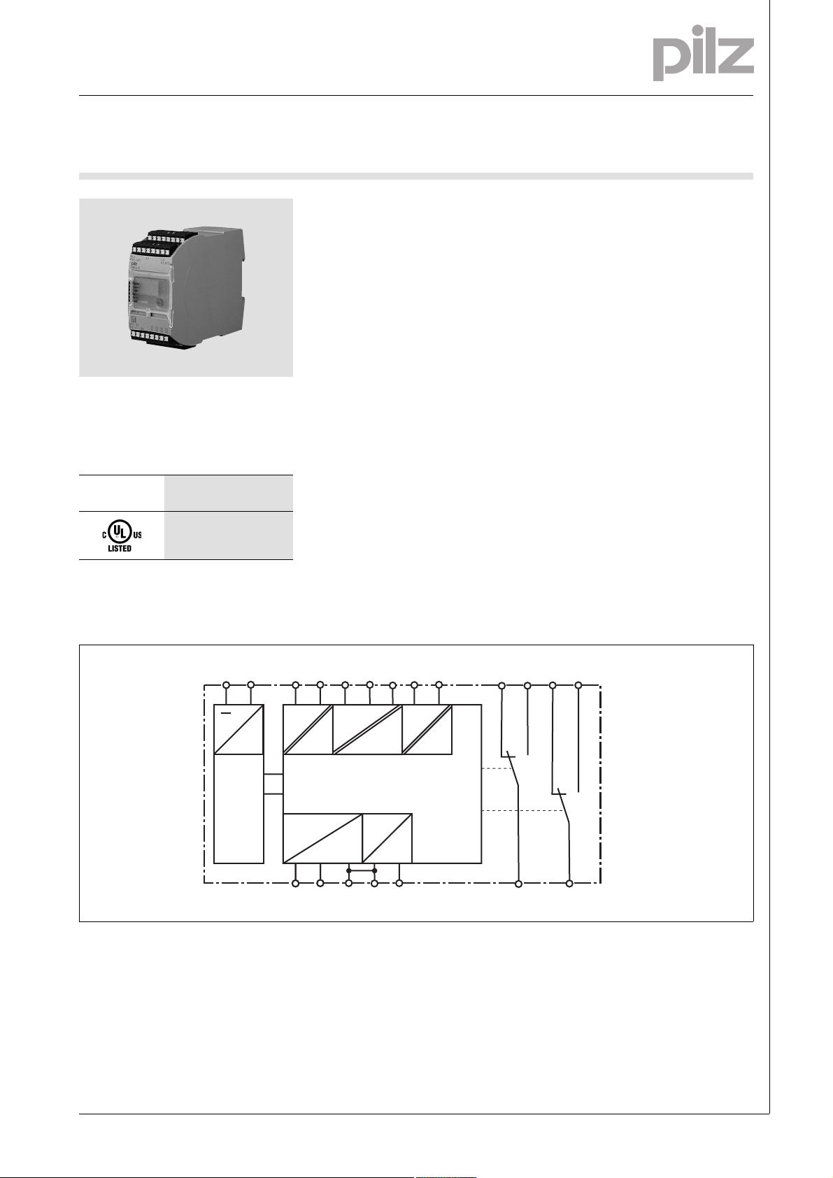
Block diagram
A1 A2
~
Power
Power
Blockschaltbild
K1 U/I1 24
I
M1
L1 L2 L3
U
M
K3 W/I3
I
M3
12
=
K1
P
U
out Iout
U I 0 V
Reset
Y2 Y1
K2
11
14
22
21
NSG-D-2-422-2010-11
Page 2
Electronic monitoring relays PMDsigma
True power monitoring
PMD s10
Function description
Funktionsbeschreibung_Text_1
The PMD s10 monitors the true power
on a single, three phase or DC supply
to ensure it doesn't exceed or drop
below a certain value. The unit operates in accordance with the Aron circuit principle.
Relay outputs (K1 and K2)
K1 and K2 operate in normally energised mode. In their default state, auxiliary contacts 11-14 and 21-24 are
closed and auxiliary contacts 11-12
and 21-22 are open. Normally energised mode is the default setting; this
setting can be changed via the menu.
Analogue outputs (U
out
and I
out
):
The unit forms two output signals
which are proportional to the true
power. The limit value corresponds to
(see timing diagram). The status
P
max
of the threshold monitoring function is
displayed at the auxiliary contacts and
LEDs, along with the analogue output
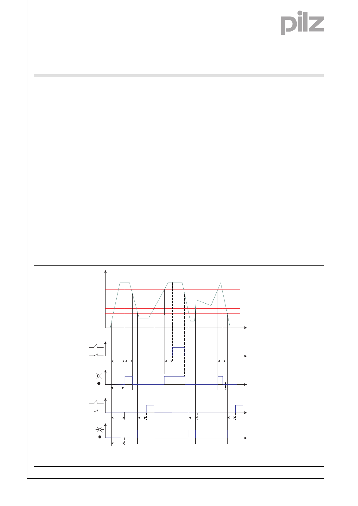
Timing diagram
signals. The hysteresis of the switching thresholds can be set between 0 %
... 50 %.
Current transformer CT:
With continuous currents > 12 A, the
measuring current must be measured
via an external current transformer.
Po function (K1 overload):
If the measured true power exceeds
the switching threshold Po, the ">
max" LED is lit. Once the response
time has elapsed (t
), the auxiliary con-
r
tact switches (default: relay K1) and
the "Out 1" LED is lit.
Pwo function (overload warning
threshold):
Serves as a warning; for function description, see Po function (K1 overload)
Funktionsbeschreibung_Text_2
Pu function (K2 underload):
If the measured true power drops below the switching threshold PU, the "<
min" LED is lit. Once the response time
has elapsed (t
), the auxiliary contact
r
switches (default: relay K2) and the
"Out 2" LED is lit.
Pwu function (underload warning
threshold):
Serves as a warning; for function description, see Pu function (K2 underload)
Start suppression time (t
Start
):
The measurement is suppressed during the machine's start-up phase, in
order to avoid spurious output signals.
The start suppression time t
Start
is infi-
nitely variable.
Response time (t
):
r
With transient load fluctuations, the
switching threshold can be suppressed. The response time t
is infi-
r
nitely variable.
Reset mode:
The fault status (value below Pu or
above Po) can be reset automatically
or via an external reset button.
P
100%
Po
Pu
5%
0%
OUT1
LED >max
OUT2
LED <min
Zeitdiagramm
ts tr tr
tr
ts
ts
tr tr
tr
Hysterese/
Hysteresis/
Hystérésis
Hysterese/
Hysteresis/
Hystérésis
t
t
t
t
P tatsächliche Wirkleistung/Actual true power/puissance active réelle
t
s Startunterdrückungszeit/Start suppression time/Temps de suppression au démarrage
t
r Reaktionszeit/Response time/Temps de résponse
ts
t
NSG-D-2-422-2010-11
-2
Page 3
Electronic monitoring relays PMDsigma
True power monitoring
PMD s10
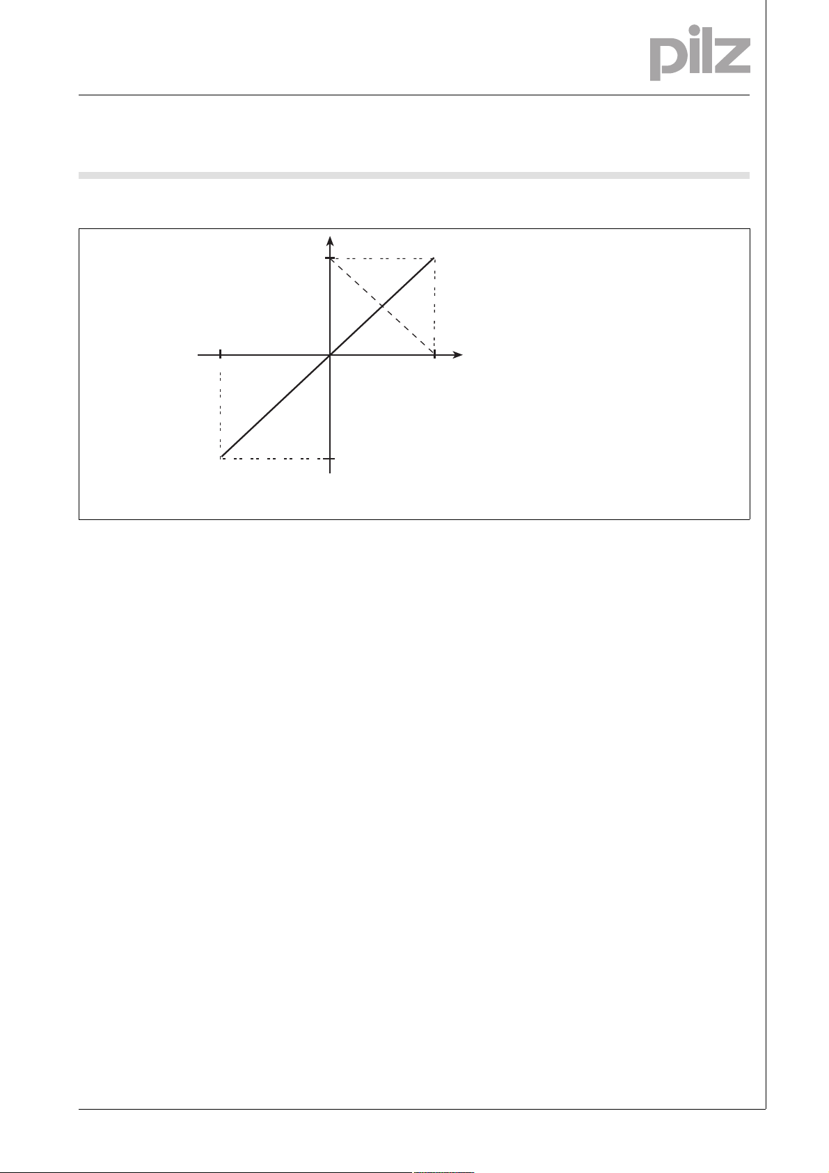
Timing diagram
Zeitdiagramm
Generatorbetrieb/
Generator/
Fonctionnement
avec générateur
-P
max
U
P tatsächliche Wirkleistung/Actual true power/puissance active réelle
U/I analoges Ausgangssignal, Spannung oder Strom/Analogue output signal, voltage or current/
signal de sortie analogique, intensité ou tension
Wiring
Inbetriebnahme_fuer_PDB
Note:
` Only wire the unit when the supply
voltage is switched off!
` Use copper wiring.
` To prevent contact welding, a fuse
should be connected before the
output contacts (see technical details).
10 V
20 mA
4 mA
0
1* U bei/at/à 10 ... 0 V
1*
V
-10 V
U/I
Motorbetrieb/
Motor/
Fonctionnement
avec moteur
P
max
` Ensure that the cables are laid care-
fully, because an open circuit in the
measuring circuit will cause the unit
function to fail.
` Information given in the “Technical
details” must be followed.
P
W
NOTICE
Ensure that there is adequate fuse
protection on the connection cables to
terminals L1, L2, L3, K1, K3, A1 and
A2!
Preparing for operation
Inbetriebnahme_Anschluss
` Connect the supply voltage UB to
A1/A2.
` Single-phase:
– Measuring voltage U
: Connect
M
to terminals L1 and L2
– Link terminals L1-K1
– Measuring circuit: Connect
phase L1 of the motors to termi-
nal U/I1
` Three-phase:
– Measuring voltage U
: Connect
M
to terminals L1, L2 and L3
– Link terminals L1-K1, L3-K3
– Measuring circuit: Connect
phase L1 of the motor to terminal
U/I1, phase L2 to terminal L2 and
L3 to W/I3
` Please refer to the connection dia-
grams for details of how to connect
external current transformers
and an external reset (see "Application").
` Connect the output contacts in ac-
cordance with the relevant application circuit.
Leerzeilen
Inbetriebnahme_Anwendung
NOTICE
Only connect the unit as shown in the
examples below! Do not connect unlabelled terminals.
The following circuit examples show
typical applications for the true power
converter PMD s10.
With continuous currents > 12 A, the
measuring current must be measured
via an external current transformer.
NSG-D-2-422-2010-11
Page 4

Electronic monitoring relays PMDsigma
True power monitoring
PMD s10
Circuit for three-phase motor
Inbetriebnahme_Anwendung_Bild_1
L1
L2
L3
N
24V
0V
I
N
PE
K1
M1
< 12A
UVW
M3~
U/I1
Y2
I
A
V
L2
PMD s10
0V
L3
W/I3
K3
Reset
extern
A1
12 14
11
A2
22
24
21
K1
H2
L1
K1
Y1
U
NSG-D-2-422-2010-11
-4
Page 5

Electronic monitoring relays PMDsigma
True power monitoring
PMD s10
Circuit for three-phase motor with CT
Inbetriebnahme_Anwendung_Bild_2
L1
L2
L3
N
24V
0V
k
K
L
k
K
L
l
l
L1
K1
U/I1
L2
PMD s10
L3
W/I3
K3
Reset
extern
I
N
PE
K1
M1
> 12A
UVW
M3~
Y1
Y2
U
I
A
V
11
0V
21
12 14
22
A1
A2
24
K1
H2
NSG-D-2-422-2010-11
Page 6

Electronic monitoring relays PMDsigma
True power monitoring
PMD s10
Circuit for motor (1 AC)
Inbetriebnahme_Anwendung_Bild_3
L1
N
24V
0V
I
N
PE
K1
M1
< 12A
U/I1
Y2
I
A
V
L2
PMD s10
0V
L3
W/I3
K3
Reset
extern
A1
12 14
11
A2
22
24
21
K1
H2
L1
K1
Y1
U
U2
U1
M1~
NSG-D-2-422-2010-11
-6
Page 7

Electronic monitoring relays PMDsigma
True power monitoring
PMD s10
Circuit for motor (1 AC) with CT
Inbetriebnahme_Anwendung_Bild_4
L1
Inbetriebnahme
U/I1
L2
PMD s10
L3
W/I3
K3
Reset
extern
L1
K1
24V
N
0V
k
K
L
l
K1
U2
U1
M1
M1~
I
> 12A
N
PE
Parameter setting
Funktionsbeschreibung
Parameters such as switching thresholds, start-up suppression time, reaction time and rest mode, for example,
are set via a rotary knob.
Installation
Montage_Sigma_allgemein
` The unit should be installed in a
control cabinet with a protection
type of at least IP54.
` Use the notch on the rear of the unit
to attach it to a mounting rail.
` In environments exposed to heavy
vibration or when installing on a vertical mounting rail (35 mm), the unit
should be secured using a fixing element (e.g. retaining bracket or end
angle).
` Push the unit upwards or down-
wards before lifting it from the
mounting rail.
Y1
Y2
U
I
A
V
11
0V
21
12 14
22
A1
A2
24
K1
A display indicates the current values
plus the set values.
The parameters can be saved on a
chip card. This chip card can be used
H2
as a backup copy of the parameters or
can be used to transfer the parameters
to another unit.
NSG-D-2-422-2010-11
Page 8

Electronic monitoring relays PMDsigma
True power monitoring
PMD s10
Notice
][WICHTIG_PDB_alt
This data sheet is only intended for use
Montage
during configuration. For installation
and operation, please refer to the operating instructions supplied with the
unit.
Technical details
Electrical data
Supply voltage UB AC/DC 24 - 240 V
Voltage tolerance -20 %/+10 %
Power consumption at U
Power consumption at U
Frequency range AC 50 - 60 Hz
Utilisation category in accordance with EN 60947-4-1
Auxiliary contacts: AC1 at 240 V I
Auxiliary contacts: DC1 at 24 V I
Utilisation category in accordance with EN 60947-5-1
Auxiliary contacts: AC15 at 230 V I
Auxiliary contacts: DC13 at 24 V (6 cycles/min) I
Contact material AgNi10
External contact fuse protection (I
Blow-out fuse, quick
Auxiliary contacts: 6 A
Blow-out fuse, slow
Auxiliary contacts: 4 A
Circuit breaker 24 VAC/DC, characteristic B/C
Auxiliary contacts: 4 A
Safety-related characteristic data
PL in accordance with EN ISO 13849-1 PL c (Cat. 1)
Category in accordance with EN 954-1 Cat. 1
SIL CL in accordance with EN IEC 62061 SIL CL 1
PFH in accordance with EN IEC 62061 6.05E-07
SIL in accordance with IEC 61511 SIL 1
PFD in accordance with IEC 61511 5.30E-02
t
in years 20
M
Times
Typ. response time of analogue output at DC 20 ms
Response time of analogue output at 15 ... 60 Hz 70 - 16 ms
Response time of analogue output at 60 ... 400 Hz 16 ms
Response time t
of auxiliary contact (selectable) 0.01 - 30.00 s
r
Start suppression time t
Measuring circuit
Measuring voltage UM (AC/DC) 100 - 550 V
Measuring current I
Frequency range 0, 15 - 400 Hz
Measuring range limit value (selectable) 1.0 W - 11.5 kW
Measuring range limit value P
Performance range of 1 A current transformer 1.5 - 7.5 VA
Performance range of 5 A current transformer 2.5 - 15.0 VA
Current transformer class 3
Max. measuring current AC/DC 12 A
Temperature coefficient 0.10 %/K
AC 5.0 VA
B
DC 3.0 W
B
min
P
max
min
P
max
max
max
= 1 kA) to EN 60947-5-1
K
(selectable) 0.0 - 30.0 s
start
(AC/DC) 1 - 12 A
M
with external current transformer 100.0 W - 11.5 MW
max
: 0.10 A , I
: 1200 VA
: 0.10 A , I
: 120 W
: 5.0 A
: 2.0 A
max
max
Technische Daten PMD s1 0
: 5.0 A
: 5.0 A
NSG-D-2-422-2010-11
-8
Page 9

Electronic monitoring relays PMDsigma
True power monitoring
PMD s10
Output signals during motor operation
Output voltage U
Output voltage U
Terminating impedance (apparent ohmic resistance) R
Output current I
Output current I
Terminating impedance (apparent ohmic resistance) R
Output signals during generator operation
Output voltage U
Terminating impedance (apparent ohmic resistance) R
Output current I
Terminating impedance (apparent ohmic resistance) R
Environmental data
EMC EN 61000-6-2, EN 61000-6-4
Vibration to EN 60068-2-6
Frequency 10 - 55 Hz
Amplitude 0.35 mm
Climatic suitability EN 60068-2-78
Airgap creepage in accordance with IEC 60664-1
Pollution degree 2
Overvoltage category III
Rated insulation voltage 300 V
Rated impulse withstand voltage
Measuring circuit 6.0 kV
Supply voltage, auxiliary contacts, analogue output 4.0 kV
Ambient temperature -10 - 55 °C
Storage temperature -25 - 85 °C
Protection type
Mounting (e.g. cabinet) IP54
Housing IP40
Terminals IP20
Mechanical data
Housing material
Housing PC
Front PC
Cross section of external conductors with screw terminals
1 core flexible 0.25 - 2.50 mm² , 24 - 12 AWG No. 760100
with crimp connectors, without insulating sleeve 0.25 - 1.00 mm² , 24 - 16 AWG No. 760100
without crimp connectors or with TWIN crimp connectors 0.20 - 1.50 mm² , 24 - 16 AWG No. 760100
Torque setting with screw terminals 0.50 Nm No. 760100
Cross section of external conductors with spring-loaded terminals: Flexible with/without crimp connectors
Stripping length 9 mm No. 761100
Dimensions
Height 100.0 mm No. 761100
Width 45.0 mm
Depth 120.0 mm
Weight 370 g
0... 10 V 0 - 10 V
out
10 ... 0 V 10 - 0 V
out
4 ... 20 mA 4 - 20 mA
out
0 ... 20 mA 0 - 20 mA
out
out
0 - -20 mA
out
Bestelldaten
min. 1 kOhm
out
max. 0.5 kOhm
out
0 - -10 V
min. 1 kOhm
out
max. 0.5 kOhm
out
0.20 - 2.50 mm² , 24 - 12 AWG No. 761100
98.0 mm No. 760100
Order reference
Type Features Terminals Order no.
PMD s10 24 - 240 V AC/DC With screw terminals 760 100
PMD s10 C 24 - 240 V AC/DC With cage clamp terminals 761 100
NSG-D-2-422-2010-11
 Loading...