

Page 1

Artisan Technology Group is your source for quality
new and certied-used/pre-owned equipment
• FAST SHIPPING AND
DELIVERY
• TENS OF THOUSANDS OF
IN-STOCK ITEMS
• EQUIPMENT DEMOS
• HUNDREDS OF
MANUFACTURERS
SUPPORTED
• LEASING/MONTHLY
RENTALS
• ITAR CERTIFIED
SECURE ASSET SOLUTIONS
SERVICE CENTER REPAIRS
Experienced engineers and technicians on staff
at our full-service, in-house repair center
Instra
Remotely inspect equipment before purchasing with
our interactive website at www.instraview.com
Contact us: (888) 88-SOURCE | sales@artisantg.com | www.artisantg.com
SM
REMOTE INSPECTION
View
WE BUY USED EQUIPMENT
Sell your excess, underutilized, and idle used equipment
We also offer credit for buy-backs and trade-ins
www.artisantg.com/WeBuyEquipment
LOOKING FOR MORE INFORMATION?
Visit us on the web at www.artisantg.com for more
information on price quotations, drivers, technical
specications, manuals, and documentation
Page 2

Motion Control PMC
PMCprimo Drive2
Installation Manual – Item No. 21 486-02
Artisan Technology Group - Quality Instrumentation ... Guaranteed | (888) 88-SOURCE | www.artisantg.com
Page 3

1 General conditions
1.1 Copyright
Copyright 2005 Pilz GmbH & Co. KG
All rights reserved. No part of this document may be reproduced in any form (print, photocopy,
microfilm or any other format), or modified, duplicated by electronic means, without written
authorization by Pilz GmbH & Co. KG.
1.2 Notes
Pilz GmbH & Co. KG reserves the right to make amendments to this document at any time.
The examples given serve only as illustrations. No guarantee is given for their suitability in
particular applications. Although the utmost care has been taken in the production of this document,
no liability can be accepted for any mistakes that it may contain. We welcome any suggestions for
the improvement of our products, or documentation.
We reserve the right to make technical changes, which lead to the improvement of the product!
1 General conditions
1.3 Previous editions
Edition Comments
V1 Initial release
V2 Revision
Page 2 Installation manual PMCprimo Drive2
Artisan Technology Group - Quality Instrumentation ... Guaranteed | (888) 88-SOURCE | www.artisantg.com
Page 4

2 Table of contents
2 Table of contents
1 General conditions ........................................................................................... 2
1.1 Copyright ................................................................................................................. 2
1.2 Notes ....................................................................................................................... 2
1.3 Previous editions ..................................................................................................... 2
2 Table of contents.............................................................................................. 3
3 Type key ............................................................................................................ 6
4 Safety instructions ........................................................................................... 7
5 European directives and standards................................................................ 8
6 Abbreviations and symbols............................................................................. 10
7 General .............................................................................................................. 11
7.1 About this manual.................................................................................................... 11
7.2 Requirements .......................................................................................................... 11
7.3 Prescribed use (Use as directed) of the control....................................................... 11
7.4 Instrument description .............................................................................................13
7.4.1 Scope of delivery.............................................................................................. 13
7.4.2 Accessories ...................................................................................................... 13
7.4.3 The PMCprimo Drive2 family............................................................................ 14
7.4.3.1 Performance data ....................................................................................14
7.4.3.2 Fieldbus Interface ....................................................................................14
7.4.3.3 Soft-PLC CoDeSys®................................................................................ 14
7.4.3.4 Interfaces ................................................................................................. 14
7.4.3.5 Power supplies ........................................................................................ 14
7.4.3.6 Power section ..........................................................................................15
7.4.3.7 Electrical supply.......................................................................................15
7.4.3.8 Power input filter ...................................................................................... 15
7.4.3.9 Operation and programming .................................................................... 15
7.4.3.10 Integrated safety.....................................................................................15
7.5 Connection to different mains supply networks .......................................................16
7.6 Block diagram – part 1............................................................................................. 17
7.7 Block diagram – part 2............................................................................................. 18
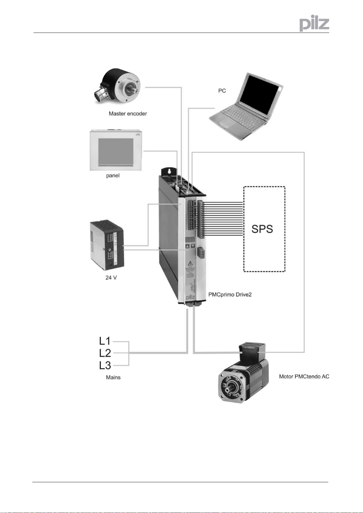
7.8 Components of a servo system ............................................................................... 19
7.9 Technical data .........................................................................................................20
7.9.1 External fusing.................................................................................................. 21
7.9.2 Permissible ambient conditions ventilation, mounting position ......................... 21
7.9.3 Conductor cross-sections ................................................................................. 22
7.9.4 LED-Display .....................................................................................................22
7.10 Grounding system ................................................................................................... 23
7.11 Control for motor-holding brake .............................................................................. 23
7.12 Regen circuit ........................................................................................................... 25
7.13 Switch-on and switch-off behaviour......................................................................... 26
7.13.1 Stop function to EN 60204 (VDE 0113) .......................................................... 26
7.13.2 Emergency Stop strategies ............................................................................ 27
7.13.2.1 Category 0.............................................................................................. 27
7.13.2.2 Category 1.............................................................................................. 27
7.14 Option -AS .............................................................................................................. 28
7.14.1 General........................................................................................................... 28
7.14.2 Prescribed use................................................................................................ 28
7.14.3 Functional description..................................................................................... 29
7.14.4 Block diagram.................................................................................................30
7.14.5 Signal diagram ............................................................................................... 30
7.14.6 Installation and Commissioning......................................................................31
7.14.6.1 Safety instructions ..................................................................................31
7.14.6.2 Application example................................................................................ 31
7.14.6.3 Connection diagram................................................................................ 31
8 Installation......................................................................................................... 32
8.1 Important instructions .............................................................................................. 32
Installation manual PMCprimo Drive2 Page 3
Artisan Technology Group - Quality Instrumentation ... Guaranteed | (888) 88-SOURCE | www.artisantg.com
Page 5

2 Table of contents
8.2 Assembly.................................................................................................................33
8.3 Dimensions.............................................................................................................. 34
8.4 Wiring ......................................................................................................................35
8.4.1 Connection diagram PMCprimo Drive2 - part 1................................................37
8.4.2 Connection diagram PMCprimo Drive2- part 2.................................................38
8.4.3 Pin assignments overview ................................................................................ 39
8.4.4 Pin assignments - details.................................................................................. 40
8.4.5 Pin assignments Modbus/Profibus ...................................................................41
8.4.6 Notes on connection techniques....................................................................... 42
8.5 Key operation for parameter setting ........................................................................43
8.5.1 Comparison to the key operation with PMCtendo DD4 .................................... 43
8.5.2 Basic key operation .......................................................................................... 43
8.5.3 Menu operation................................................................................................. 43
8.5.4 LED Display...................................................................................................... 44
8.5.5 Automatic detection in PMCprimo ....................................................................44
9 Interfaces........................................................................................................... 45
9.1 Power supply...........................................................................................................45
9.1.1 Mains supply (X0)............................................................................................. 45
9.1.2 24V-auxiliary supply (X4).................................................................................. 46
9.1.3 24V-Supply (X10) ............................................................................................. 47
9.1.4 Master encoder supply (X10) .......................................................................... 48
9.1.5 DC-link (X7)......................................................................................................49
9.2 Motor connection with brake (X9)............................................................................49
9.2.1 Lead length < 25m............................................................................................ 49
9.2.2 Lead length > 25m............................................................................................ 50
9.3 External regen resistor (X8)..................................................................................... 51
9.4 Feedback................................................................................................................. 52
9.4.1 Resolver connection (X2) ................................................................................. 52
9.4.2 HIPERFACE Encoder (X1)...............................................................................53
9.5 Encoder emulations.................................................................................................54
9.5.1 Incremental encoder emulation ROD (X5)........................................................ 54
9.5.2 Application example .........................................................................................54
9.5.3 SSI emulation (X5) ...........................................................................................55
9.5.4 Application example .........................................................................................55
9.6 RS232 interface, PC interface (X6) .........................................................................56
9.6.1 General............................................................................................................. 56
9.6.2 Pin assignment of the null-modem cable..........................................................57
9.7 Digital signals ..........................................................................................................59
9.7.1 Digital inputs I1:1 - I1:8 (X10) ........................................................................... 59
9.7.2 Digital inputs I2:1 - I2:4 (X3) ............................................................................. 60
9.7.3 Digital ENABLE input (X3)................................................................................61
9.7.4 Digital outputs O1:1 - O1:8 (X10) ....................................................................62
9.7.5 Digital outputs Digital-Out 1+2 (X3) .................................................................. 63
9.7.6 Relay output (X3)..............................................................................................64
9.8 Analog signals ......................................................................................................... 65
9.8.1 Analog outputs AO2 and AO3 (X3)................................................................... 65
9.8.2 Analog inputs AI1 and AI2 (X3) ........................................................................66
9.9 CAN bus interface (X11/2 and X11/1) .....................................................................67
9.9.1 General............................................................................................................. 67
9.9.2 Connecting PMCprimo Drive2 systems............................................................67
9.9.3 CAN bus cable.................................................................................................. 68
9.9.4 Speciality 1st node ...........................................................................................68
9.9.5 Speciality last node........................................................................................... 68
9.9.6 Fault detection..................................................................................................68
9.9.7 Connecting external CANopen bus devices ..................................................... 68
9.10 Master encoder interface / CAN2 (X11/4) ...............................................................69
9.10.1 CAN 2 interface .............................................................................................. 70
9.10.2 Jumper settings .............................................................................................. 71
9.10.3 Incremental encoder.......................................................................................72
9.10.4 Absolute encoder (SSI) ..................................................................................73
9.11 Bus interface (X11/3) ..............................................................................................74
9.11.1 General........................................................................................................... 74
9.11.2 MODBUS Interface......................................................................................... 74
9.11.3 Profibus interface (Option).............................................................................. 75
9.11.4 Using the MODBUS / Profibus interface with PMCprimo................................ 75
9.11.5 Example: Profibus DP slave module ..............................................................75
9.12 Virtual inputs and outputs........................................................................................ 77
9.12.1 Terms ............................................................................................................. 77
9.12.2 Application example .......................................................................................77
Page 4 Installation manual PMCprimo Drive2
Artisan Technology Group - Quality Instrumentation ... Guaranteed | (888) 88-SOURCE | www.artisantg.com
Page 6

2 Table of contents
10 Commissioning................................................................................................. 78
10.1 Important notes ....................................................................................................... 78
10.2 Setup software PDRIVE..........................................................................................80
10.2.1 Use as directed............................................................................................... 80
10.2.2 Software description....................................................................................... 80
10.2.3 Hardware requirements .................................................................................. 80
10.2.4 Minimum requirements for the PC:.................................................................80
10.2.5 Installation under WINDOWS 95 / 98 / NT / 2000 / XP................................... 80
10.2.6 Working with PDRIVE..................................................................................... 80
10.3 Parametrization of the PMCprimo Drive2................................................................81
10.4 Programming of the PMCprimo Drive2 ................................................................... 81
10.5 Error messages....................................................................................................... 82
10.5.1 Error messages PMCprimo ............................................................................82
10.5.2 Error messages amplifier................................................................................ 83
10.6 Warnings.................................................................................................................84
10.7 Status messages..................................................................................................... 85
10.7.1 Status messages PMCprimo .......................................................................... 85
10.7.2 Status messages drive ................................................................................... 85
11 Appendix ........................................................................................................... 86
11.1 Notes on EMC problems ......................................................................................... 86
11.1.1 Cable screening.............................................................................................. 86
11.1.2 Metallic, large area connections ..................................................................... 87
11.1.3 PE connection, earthing, grounding................................................................ 87
11.1.4 Motor choke.................................................................................................... 87
11.1.5 Expansion board............................................................................................. 88
11.1.6 Ethernet interface of the expansion board X11/5 ........................................... 88
11.1.6.1 General...................................................................................................88
11.1.6.2 Interface.................................................................................................. 89
11.1.6.3 Configuration IP address ........................................................................90
11.2 Change of the buffer battery ...................................................................................92
11.3 Transport, storage, maintenance, disposal ............................................................. 93
11.4 Removing faults ......................................................................................................94
11.5 Index ....................................................................................................................... 96
Installation manual PMCprimo Drive2 Page 5
Artisan Technology Group - Quality Instrumentation ... Guaranteed | (888) 88-SOURCE | www.artisantg.com
Page 7
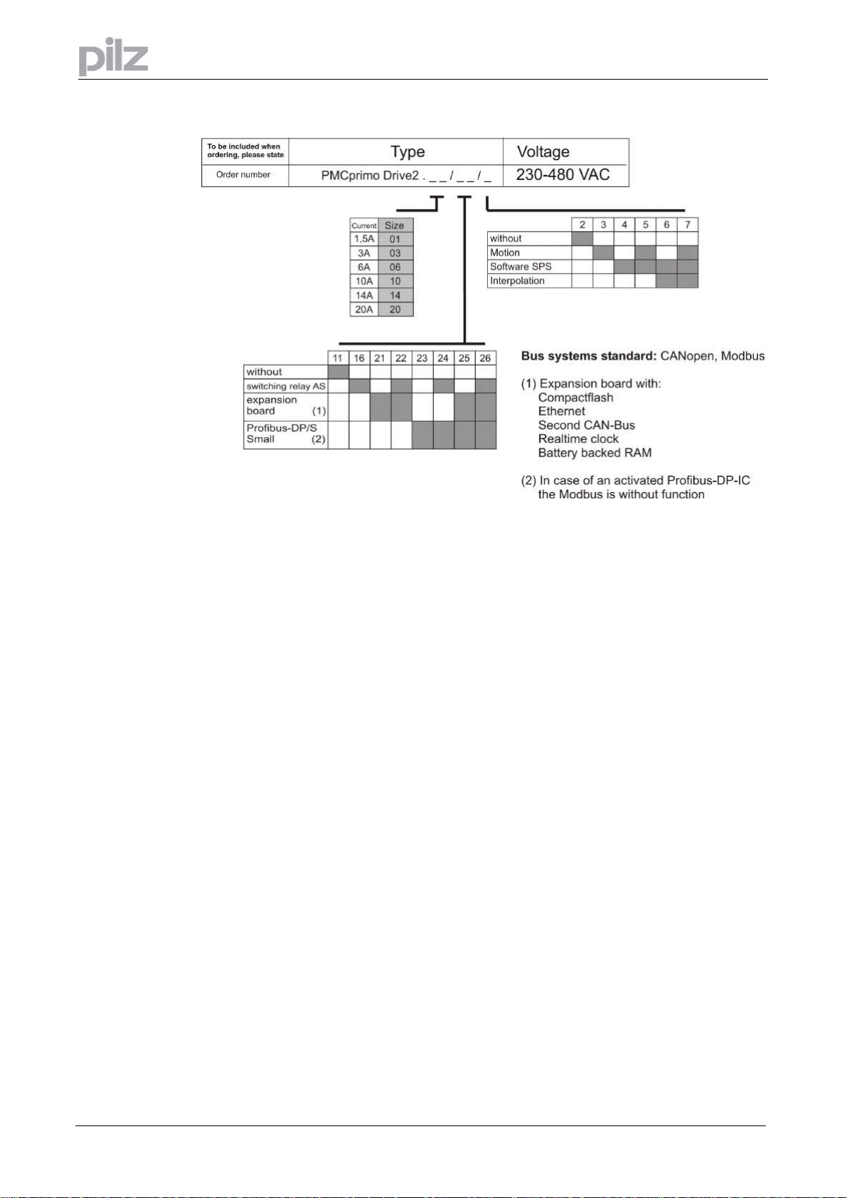
3 Type key
3 Type key
Page 6 Installation manual PMCprimo Drive2
Artisan Technology Group - Quality Instrumentation ... Guaranteed | (888) 88-SOURCE | www.artisantg.com
Page 8

4 Safety instructions
4 Safety instructions
Only properly qualified personnel are permitted to perform activities such as
transport, installation, commissioning and maintenance. Properly qualified
persons are those who are familiar with the transport, assembly, installation,
commissioning and operation of the product, and who have the appropriate
qualifications for their job. The qualified personnel must know and observe:
IEC 364 and CENELEC HD 384 or DIN VDE 0100
IEC-Report 664 or DIN VDE 0110
National Accident Prevention Regulations or BGV A2
Read this documentation before carrying out installation and commissioning.
Incorrect handling of the PMCprimo Drive
damage. It is vital that you keep to the technical data and information on
connection requirements (on the nameplate and in the documentation).
The PMCprimo Drive2
be damaged by incorrect handling. Discharge your body before touching the
PMCprimo Drive2. Avoid contact with highly insulating materials (synthetic fibre,
plastic film etc.). Place the PMCprimo Drive2
Do not open the units. Keep all covers and switchgear cabinet doors closed during
operation. Otherwise there are deadly hazards, with the possibility of severe
danger to health or material damage.
During operation, PMCprimo Drives, according to their degree of enclosure
protection, may have uncovered live components. Control and power connections
may be live, even if the motor is not rotating.
PMCprimo Drives
used for cooling, it can reach temperatures above 80°C.
Never undo the electrical connections to the PMCprimo Drive2
is a danger of electric arcing with damage to contacts and danger to persons.
Wait at least five minutes after disconnecting the PMCprimo Drive2
supply voltage before touching live sections of the equipment (e.g. contacts) or
undoing connections. Capacitors can still have dangerous voltages present up to
five minutes after switching off the supply voltages. To be sure, measure the
voltage in the DC-link circuit and wait until it has fallen below 40V.
Based on the guideline 94/9/EC (ATEX guideline) this product is not suitable for the
application in potential explosive areas without evaluation of the conformity.
contains electrostatically sensitive components which may
may have hot surfaces during operation. Since the front panel is
can lead to personal injury or material
on a conductive surface.
while it is live. There
from the mains
Installation manual PMCprimo Drive2 Page 7
Artisan Technology Group - Quality Instrumentation ... Guaranteed | (888) 88-SOURCE | www.artisantg.com
Page 9

5 European directives and standards
Servo amplifiers are components that are intended to be incorporated into electrical plant and
machines forindustrial use. When the servoamplifiers are built into machines or plant, the intended
operation of the amplifier is forbidden until it has been established that the machine or plant fulfills
the requirements of the EC Machinery Directive 98/37/EG and the EC Directive on EMC
(89/336/EEC).
To fulfill the EC Machinery directive (98/37/EG), the following standards have to be applied: EN
60204-1 (Safety and electrical equipment of machines) EN 292 (Safety of machines)
The manufacturer of the machine must produce a hazard analysis for the machine and take
appropriate measures to ensure that unforeseen movements do not result in personal injury
or material damage.
To fulfill the Low Voltage Directive 73/23/EEC, the following standards have to be applied:
EN 60204-1 (Safety and electrical equipment of machines)
EN 50178 (Equipment of high voltage plant with electronic devices)
EN 60439-1 (Low-voltage switchgear and controlgear assemblies)
To fulfill the EC EMC regulations (89/336/EEC), the following standards have to be applied:
EN 61000-6-1 or EN 61000-6-2 (noise immunity within the domestic range/industrial range)
EN 61000-6-3 or EN 61000-6-4 (noise emission within the domestic range/industrial range)
The manufacturer of the machine or plant is responsible for ensuring that they meet the limits
required by the EMC regulations. Advice on the correct installation for EMC – such as shielding,
grounding, arrangement ofconnectors and cable routing – can be found in this documentation.
The machine / plant manufacturer must examine whether with its machine / plant still further
or other standards or EEC guidelines are to be used.
5 European directives and standards
ce- conformance
Conformity with the EC Directive on EMC 89/336/EEC and the Low Voltage Directive 73/23/EEC is
mandatory for servoamplifiers supplied within the European Union. To fulfill the EMC directive, the
standard EN 61800-3 is applied.
In the reference to noise immunity and noise emission the servoamplifier fulfills the requirement to
the category second environment (industrial environment).
The servo amplifiers have been tested by an authorized testing laboratory in a defined configuration
with the system components which are described in this documentation. Any divergence from the
configuration and installation described in this documentation means that you will be responsible for
carrying out new measurements to ensure that the regulatory requirements are fulfilled.
To fulfill the Low Voltage Directive, the standard EN 50178 has to be applied.
Page 8 Installation manual PMCprimo Drive2
Artisan Technology Group - Quality Instrumentation ... Guaranteed | (888) 88-SOURCE | www.artisantg.com
Page 10

5 European directives and standards
UL and cUL- Conformance
UL (cUL)-certified servo amplifiers (Underwriters Laboratories Inc.) fulfil the relevant U.S. and
Canadian standard (in this case UL 840 and UL 508C).
This standard describes the fulfillment by design of minimum requirements for electrically operated
power conversion equipment, such as frequency converters and servo amplifiers, which is intended
to eliminate the risk of fire, electric shock, or injury to persons, being caused by such equipment.
The technical conformance with the U.S. and Canadian standard is determined by an independent
UL (cUL) fire inspector through the type testing and regular check-ups.
Apart from the notes on installation and safety in the documentation, the customer does not have to
observe any other points in direct connection with the UL (cUL)-certification of the equipment.
UL 508C
UL 508C describes the fulfillment by design of minimum requirements for electrically operated
power conversion equipment, such as frequency converters and servo amplifiers, which is intended
to eliminate the risk of fire being caused by such equipment.
UL 840
UL 840 describes the fulfillment by design of air and insulation creepage spacings for electrical
equipment and printed circuit boards.
Installation manual PMCprimo Drive2 Page 9
Artisan Technology Group - Quality Instrumentation ... Guaranteed | (888) 88-SOURCE | www.artisantg.com
Page 11
6 Abbreviations and symbols
The abbreviations used in this manual are explained in the table below.
Abbrev. Meaning
AGND Analog ground
BTB/RTO Ready to operate
CAN Controller area network- Bus system
CE Communité Europeenne
CLK Clock
COM Serial interface of a PC-AT
DGND Digital ground
DIN Deutsches Institut für Normung
Drive Servo amplifier
EGND Ground for PMCprimo Drive2, RS232 and encoder
EMC Electromagnetic compatibility
EN Europäische Norm
ESD Electrostatic discharge
IEC International Electrotechnical Commission
IGBT Insulated Gate Bipolar Transistor
ISO International Standardization Organization
MODBUS Serial protocol for operator manuals
NI Zero pulse
RBallast Regen resistor
RBext External regen resistor
RBint Internal regen resistor
RES Revolver
PLC Programmable logic controller
SRAM Static RAM
SSI Synchronous serial interface
TN/TT-Netz Mains standard DIN 57100 T310
UL Underwriter Laboratories
V AC AC voltage
V DC DC voltage
VDE Verein deutscher Elektrotechniker
VGA Grafical display with min. 640x480 pixels
XGND Ground for the 24V supply
6 Abbreviations and symbols
Meaning/Description
This symbol indicates the possibility of a danger, risk to life and/or health.
Ignorance may seriously affect health and cause dangerous injuries.
This symbol indicates the possibility of a danger, risk to life and/or health from
electricity and its effects.
•
⇒
This symbol indicates important instructions regarding the correct use of the
product. Ignorance may affect the performance of the machinery and/or the
connected system.
This symbol indicates special user tips and/or important useful information.
These will support optimum use of the product and functions.
Emphasis
see page (or cross reference)
Page 10 Installation manual PMCprimo Drive2
Artisan Technology Group - Quality Instrumentation ... Guaranteed | (888) 88-SOURCE | www.artisantg.com
Page 12

7 General
7 General
7.1 About this manual
This manual describes the digital control system PMCprimo Drive2.
Here you can find information about:
• Technical data of the PMCprimo Drive2 from page 20
• Assembly and installation from page 32
• Interfaces from page 45
• Commissioning of the PMCprimo Drive2 from page 78
The programming of the PMCprimo-motion control-systems is described explicitely in the
PMCprimo programming manual.
Useful hints about linking controls and CANopen devices via CAN bus can be found in the
manual „PMCprimo CAN network“.
Both manuals are part on the CD-ROM PMCprimo Motion Control Tools.
7.2 Requirements
Transport: only by personnel with knowledge in handling electrostatically
sensitive components.
Installation: only by electrically qualified personnel
Commissioning: only by personnel with extensive knowledge of electrical
engineering technology
7.3 Prescribed use (Use as directed) of the control
The servo amplifiers are components which are built into electrical equipment or machines, and can
only be used as integral components of such equipment.
The manufacturer of the machine must generate a hazard analysis for the machine, and take
appropriate measures to ensure that unforeseen movements cannot cause injury or damage to any
person or property.
The PMCprimo Drive2 family of servo amplifiers can be connected directly to symmetrically earthed
(grounded) three-phase industrial mains supply networks [TN-system, TT-system with earthed
(grounded) neutral point, not more than 5000 rms symmetrical amperes, 480 VAC maximum].
The servo amplifiers must not be operated directly on power supply networks >230 V without an
earth (ground) or with an asymmetrical earth (ground).
Connection to different mains supply networks (with additional isolating transformer) (page 16).
Periodic overvoltages between outer conductor (L1, L2, L3) and housing of the servo amplifier may
not exceed 1000 V (peak value).
Transient overvoltages (< 50µs) between the outer conductors may not exceed 1000 V.
Transient overvoltages (< 50µs) between outer conductors and housing may not exceed 2000 V.
If the servo amplifiers are used in residential areas, or in business or commercial premises, then
additional filter measures must be implemented by the user.
The PMCprimo Drive2 family of servo amplifiers is intended to drive specific brushless synchronous
servomotors, with closed-loop control of torque, speed and/or position. Asynchronous and linear
motors can also be used. The rated voltage of the motors must be at least as high as the DC-link
voltage of the servo amplifier.
The servo amplifiers may only be operated in a closed switchgear cabinet, taking into account the
ambient conditions defined on page 21 and the dimensions shown on page 34. Ventilation or
cooling may be necessary to prevent enclosure ambient from exceeding 45 °C (113 °F).
Installation manual PMCprimo Drive2
Artisan Technology Group - Quality Instrumentation ... Guaranteed | (888) 88-SOURCE | www.artisantg.com
Page 11
Page 13

Use only copper wire. Wire size may be determined from EN 60204 (or table 310-16 of the NEC
60 °C or 75 °C column for AWG size).
We only guarantee the conformance of the servo amplifiers with the standards for industrial areas,
if the components (motors, cables, amplifiers etc) are delivered by Pilz GmbH & Co. KG.
7 General
Page 12
Installation manual PMCprimo Drive2
Artisan Technology Group - Quality Instrumentation ... Guaranteed | (888) 88-SOURCE | www.artisantg.com
Page 14

7 General
7.4 Instrument description
7.4.1 Scope of delivery
When you order a PMCprimo Drive2 from us, you will receive:
• PMCprimo Drive2 - size 01..20
• Mating connectors X3, X4, X0A, X0B, X7, X8
The mating motor connector X9 is not part of the package!
• Assembly, installation- and commissioning instructions
• Setup software package PMCprimo Motion Control Tools on CD-ROM
• Software manual PDrive and PMCprimo programming manual on CD-ROM
7.4.2 Accessories
• Servo motor PMCtendo AC1 or PMCtendo AC2
• Motor cable (pre-assembled), or both motor connectors separately with motor cable as cut-off
length
• Feedback cable (pre-assembled) or both feedback connectors separately with feedback cable
as cut-off length
• External regen resistor
• Communication cable to the PC for parameterisation (Null modem cable)
• MODBUS panel and communication cable; Panel (2 line till Touch screen)
• CAN cables
• Software keys for Motion Generator or Soft-PLC
• Ethernet cables
• Adapter cable Modbus/Profibus
• Expansion card (page 88)
• CompactFlash Cards
• Profibus DPS-small IC
• Master encoder
• Expansion board (page 88)
Installation manual PMCprimo Drive2
Artisan Technology Group - Quality Instrumentation ... Guaranteed | (888) 88-SOURCE | www.artisantg.com
Page 13
Page 15

7 General
7.4.3 The PMCprimo Drive2 family
7.4.3.1 Performance data
• Position controller with 1 ms cycle time
• Digital current controller (space vector, pulse-width modulation, 62,5 µs)
• Evaluation of the resolver signals or sine-cosine signals of a HIPERFACE encoder
• 9 axes in system: 1 Motor direct, as well as 8 other axes channels for controlling further axes
• Each axis can operate in virtual motor mode
• Software gearbox
• Software differential and clutch
• Internal map generator (motion generator) as an option
• Product referencing
• Tension control
• Up to 8 cam
• Soft positioning („s-curves“)
7.4.3.2 Fieldbus Interface
• CAN-Bus with 500 kBit/s or 1 MBit/s (CANopen) – linking up to 60 PMCprimo-motion controlsystems
• Modbus interface - devices like panels
• Option: Profibus DP (small) – easy communication with SoftPLC
• Option: Ethernet 10/100 Mbit/s
• Option: second CAN interface
7.4.3.3 Soft-PLC CoDeSys®
• Soft-PLC CoDeSys® as an option
• Fully PLC functionality specified in IEC 61131-3
• PLC and PMCprimo - combined in one system
7.4.3.4 Interfaces
• 12 digital inputs, 24 V, electrically isolated
• 8 digital outputs, 24 V, short circuit protected and electrically isolated
• 2 analog outputs with ± 10 V output range
• 2 analog inputs with ± 10 V input range
• 1 input for master encoder (incremental / SSI)
7.4.3.5 Power supplies
• 24 V power supply
• Common power supply for all master encoders
Page 14
Installation manual PMCprimo Drive2
Artisan Technology Group - Quality Instrumentation ... Guaranteed | (888) 88-SOURCE | www.artisantg.com
Page 16

7 General
7.4.3.6 Power section
• Power supply: B6 rectifier bridge, directly off 3-phase earthed supply system,
integral power input filter and inrush circuit
• All shielding connections directly on the amplifier
• Output stage: IGBT- module with isolated current measurement
• Regen circuit: with dynamic distribution of the regen power between several
amplifiers on the same DC-link circuit. Internal regen resistor as
standard, external regen resistors if required
• DC-link voltage 260 — 900 V DC, can be paralleled
7.4.3.7 Electrical supply
• Directly off grounded 3 phase system,
230V-10% ... 480V +10% ,50 Hz,
208V-10% ... 480V +10% ,60 Hz
TN-system or TT-system with grounded neutral point, not more than 5000 rms
symmetrical amperes
• 6 current ratings (1.5 A , 3 A , 6 A , 10 A , 14 A, 20 A)
• single-phase supply (e.g. for commissioning or setting-up) is possible
7.4.3.8 Power input filter
• Interference suppression filter for the supply input (to Class A) is integrated)
• Interference suppression filter for the 24V aux. supply (to Class A) is integrated
7.4.3.9 Operation and programming
• Comfortable programming with the software package PMCprimo Motion Control Tools under
Windows 98/NT/2000/XP.
• Fully programmable with any ASCII-Terminal
7.4.3.10 Integrated safety
• Safe electrical separation to EN 50178 between the power input / motor connections and the
signal electronics, provided by appropriate insulation/creepage distances and complete
electrical isolation
• Softstart, overvoltage recognition, short-circuit protection, phase-failure monitoring
• Temperature monitoring of PMCprimo Drive2 and motor (when using motors from the
PMCtendo AC series with our pre-assembled cables)
• -AS- built-in safety relay (personnel-safety starting lock-out).
Installation manual PMCprimo Drive2
Artisan Technology Group - Quality Instrumentation ... Guaranteed | (888) 88-SOURCE | www.artisantg.com
Page 15
Page 17

7 General
7.5 Connection to different mains supply networks
On this page you'll find all possible connection variations to different mains supply networks.
An isolating transformer is always required for 400...480V mains networks without
earth(ground) and for networks with asymmetrical earth(ground).
Page 16
Installation manual PMCprimo Drive2
Artisan Technology Group - Quality Instrumentation ... Guaranteed | (888) 88-SOURCE | www.artisantg.com
Page 18
7 General
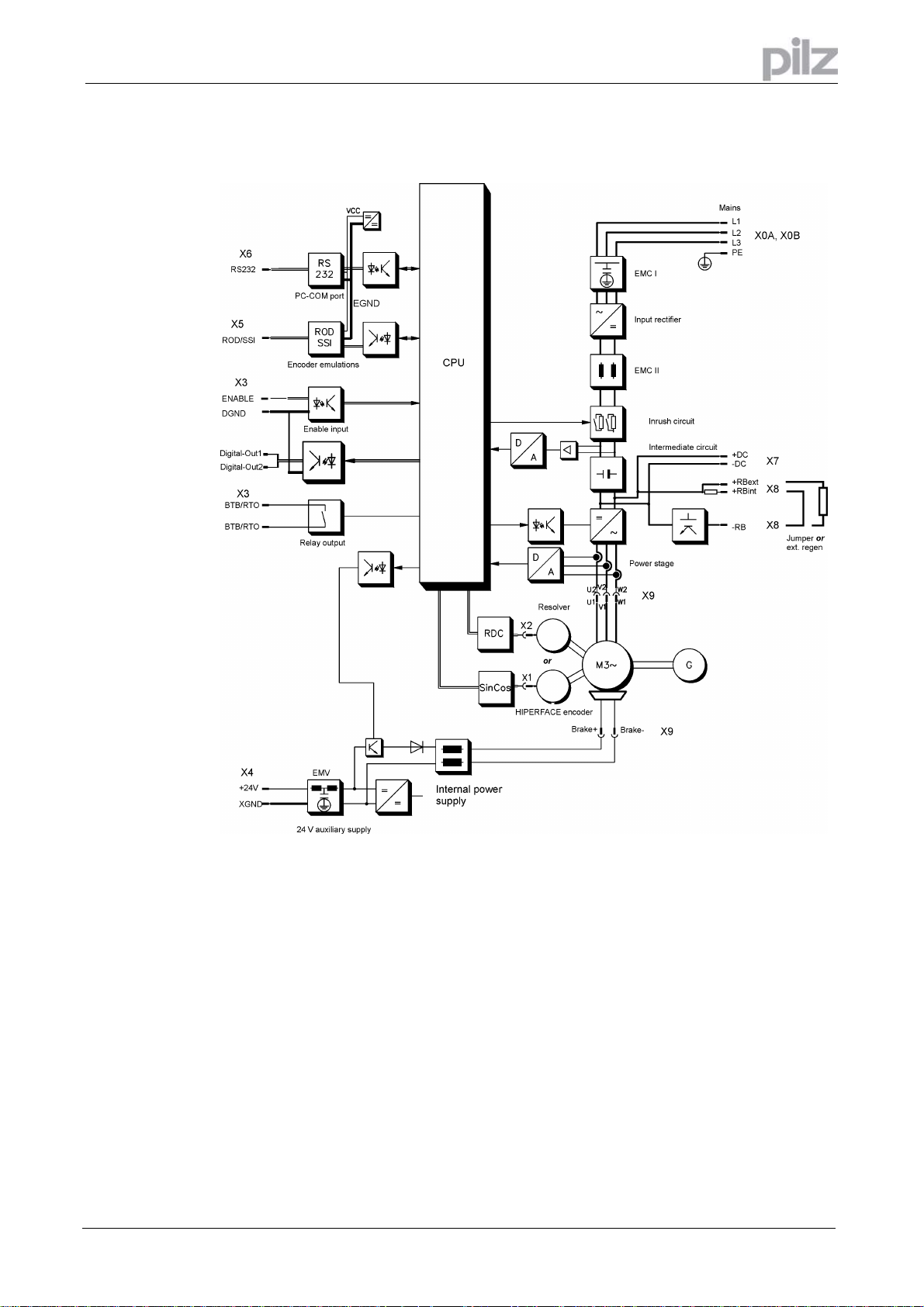
7.6 Block diagram – part 1
Installation manual PMCprimo Drive2
Page 17
Artisan Technology Group - Quality Instrumentation ... Guaranteed | (888) 88-SOURCE | www.artisantg.com
Page 19
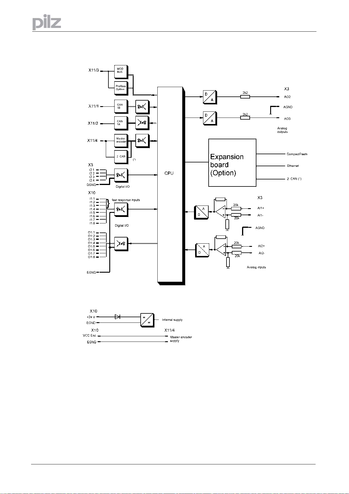
7 General
7.7 Block diagram – part 2
Page 18
Installation manual PMCprimo Drive2
Artisan Technology Group - Quality Instrumentation ... Guaranteed | (888) 88-SOURCE | www.artisantg.com
Page 20
7 General
7.8 Components of a servo system
Installation manual PMCprimo Drive2
Artisan Technology Group - Quality Instrumentation ... Guaranteed | (888) 88-SOURCE | www.artisantg.com
Page 19
Page 21

7 General
7.9 Technical data
Rated data DIM
Rated supply voltage V~ 3 x 230V-10% ... 480V+10%, 50 ... 60 Hz
Rated installed load for S1 operation kVA 1 2 4 7 10 14
Rated DC-link voltage V= 310 - 675
Rated output current (rms value, ± 3%)
Peak output current (max. ca. 5s, ± 3%)
Clock frequency of the output stage kHz 8
Technical data for regen circuit —
Overvoltage protection threshold V 450...900
Form factor of the output current
(at rated data and min. load inductance)
Bandwidth of subordinate current controller kHz > 1,2
Residual voltage drop at rated current V 5
Quiescent dissipation, output stage disabled W 15
Dissipation at rated current (incl. power
supply losses, without regen dissipation)
Internal fusing (external fusing ⇒ page 21)
Auxiliary supply 24V — internal 3.15 AT
Regen resistor — internal electronic
Inputs
Analog inputs (X3), resolution 14bit (AI1) and
12bit (AI2)
Common-mode voltage max. V ±10
Input resistance
Digital inputs (X3) according to IEC 1131
Digital inputs (X10) according to IEC 1131
Outputs
Output current digital outputs (X10), each
channel
Output current digital outputs (X3) mA max 10 (open collector)
Voltage range analog outputs (X3) ,
resolution 10 Bit
Output resistance
Max. output current, brake A 2
Master encoder PMCprimo Drive2
Input resistance
Transfer rate MHz 1
Pulse width (Z-track incremental encoder) ns mind. 200
Power dissipation
without brake, no load
with brake, no load
Encoder supply - 5-24 V, see datasheet encoder
12V supply CAN mA 10 each client
Arms 1,5 3 6 10 14 20
Arms 3 6 12 20 28 40
01 03 06 10 14 20
— 1.01
W 30 40 60 90 160 200
V ±10
kΩ
mA max. 100 (overload protection)
V ± 10
kΩ
Ω
V 24 (-0% +15%) 24 V supply supply, electrically isolated
mA 1000
V 24 (-0% +15%) 24 V supply supply, electrically isolated
mA 3000
PMCprimo Drive2
⇒ S. 24
20
2.2
200
Page 20
Installation manual PMCprimo Drive2
Artisan Technology Group - Quality Instrumentation ... Guaranteed | (888) 88-SOURCE | www.artisantg.com
Page 22

7 General
Connections DIM
Control signals (X3) — Combicon 5.08 / 18pole , 2,5mm²
24 V supply (X4) — Combicon 5.08 / 4 pole , 2,5mm²
24 V supply (X10) — Combicon 3.5 / 11 pole , 1mm²
Encoder supply (X10) — Combicon 3.5 / 11 pole , 1mm²
Digital inputs (X10) — Combicon 3.5 / 11 pole , 1mm²
Digital outputs (X10) — Combicon 3.5 / 8 pole , 1mm²
Power signals (X0,X7,X8,X9) — Power Combicon 7.62 / 4x4 + 1x6-pole, 4mm²
Resolver input (X2) — SUB-D 9pol. (plug)
HIPERFACE input (X1) — SUB-D 15pol. (plug)
PC interface (X6) — SUB-D 9pol. (socket)
Encoder emulation, ROD/SSI (X5) — SUB-D 9pole (plug)
Master encoder (X11/4) / CAN2 (Option) — SUB-D 9pole (socket)
MODBUS (X11/3) / Profibus (Option) — RJ45
CAN-1A (X11/2) — SUB-D 9pole (plug)
CAN-1B (X11/1) — SUB-D 9pole (socket)
Mechanical
Weight kg 4 5 7,5
Height without connectors mm 275
Width mm 70 100 120
Depth without connectors mm 265
01 03 06 10 14 20
PMCprimo Drive2
7.9.1 External fusing
Fusible cutouts or similay
AC supply FN1/2/3 6 AT 10 AT 20 AT
24V supply FH1/2 max. 16 AF
Regen resistor FB1/2 4 AF 6 AF 6 AF
PMCprimo Drive2
01 / 03
PMCprimo Drive2
06 / 10
7.9.2 Permissible ambient conditions ventilation, mounting position
Storage temperature/humidity,duration
Transport temperature / humidity
Supply voltage tolerances
Input power
Aux. power supply
Ambient temperature in operation
Humidity in operation rel. humidity 85%, no condensation
Site altitude up to 1000m a.m.s.l. without restriction
Pollution level Pollution level 2 to EN60204/EN50178
Enclosure protection IP 20
Mounting position
Ventilation built-in fan
Vibration Vibration: 1g sinuid according to 60068-2-Fc
⇒ S. 93
⇒ S. 93
min 3x230V
24 V DC (-0% +15%)
0...+45°C at rated data
1000...2500m a.m.s.l. with power derating 1.5%/100m
generally vertical. ⇒S. 33
Shock: 15g, 11ms, 60068-27-Ea
-10%
AC / max 3x 480V
+10%,
50 ... 60 Hz
Make sure that there is sufficient forced ventilation within the switchgear cabinet!
PMCprimo Drive2
14 / 20
Installation manual PMCprimo Drive2
Artisan Technology Group - Quality Instrumentation ... Guaranteed | (888) 88-SOURCE | www.artisantg.com
Page 21
Page 23

7 General
7.9.3 Conductor cross-sections
Following EN 60204 (for AWG: table 310-16 of the NEC 60°C or 75°C column), we recommend:
AC connection PMCprimo Drive2 sz. 01-10 : 1,5 mm²
DC-link PMCprimo Drive2 sz. 01-10 : 1,5 mm²
Motor cables up to 25 m length PMCprimo Drive2 sz. 01-10 : 1 - 1,5mm²
Motor cables 25 to 100 m length
Resolver, thermostat-motor 8x0.25 mm² twisted pairs, shielded, max.100m,
HIPERFACE Encoder, thermostatmotor
Analog In- and outputs, AGND 0.25 mm² , twisted pairs, shielded
Control signals, BTB, DGND 0.5 mm²
Holding brake (Motor) min. 0.75 mm², shielded, check voltage drop
+24 V / XGND max. 2.5 mm², check voltage drop
24 V (X10) EGND / VCC Enc. Max. 1 mm2, check voltage drop
PMCprimo Drive2 sz. 14/20 : 4 mm²
PMCprimo Drive2 sz 14/20 : 4 mm²
PMCprimo Drive2 sz. 14/20 : 2,5 mm²
PMCprimo Drive2 sz. 01-10 : 1 mm²
PMCprimo Drive2 sz. 14/20 : 2,5 mm²
capacitance <120pF/m
10x0.14 mm² twisted pairs, shielded, max.100m,
capacitance <120pF/m
600V, 105°C, twisted
shielded for length >
20 cm
shielded,
capacitance<150pF/m
shielded with motor
choke MD400
7.9.4 LED-Display
A 3-character LED displays the servo amplifiers firmware version after switching on the 24V supply
for two seconds (e.g. “2.46”).
Afterwards the status of up to 10 axes is shown (or just “run”).
When an error occurs the error number is displayed (⇒ S. 83 ).
Page 22
Installation manual PMCprimo Drive2
Artisan Technology Group - Quality Instrumentation ... Guaranteed | (888) 88-SOURCE | www.artisantg.com
Page 24
7 General
7.10 Grounding system
AGND
DGND
XGND
EGND
ground for analog inputs and outputs, internal analog ground
ground for digital inputs and outputs ( X3), optically isolated
ground for 24V aux. supply (X4)
ground for encoder-emulation, RS232, digital In-and outputs (X10); power supply PMCprimo
Drive2 and master encoder, optically and inductively isolated
The potential isolation is shown in the block diagram (⇒ S. 17/18).
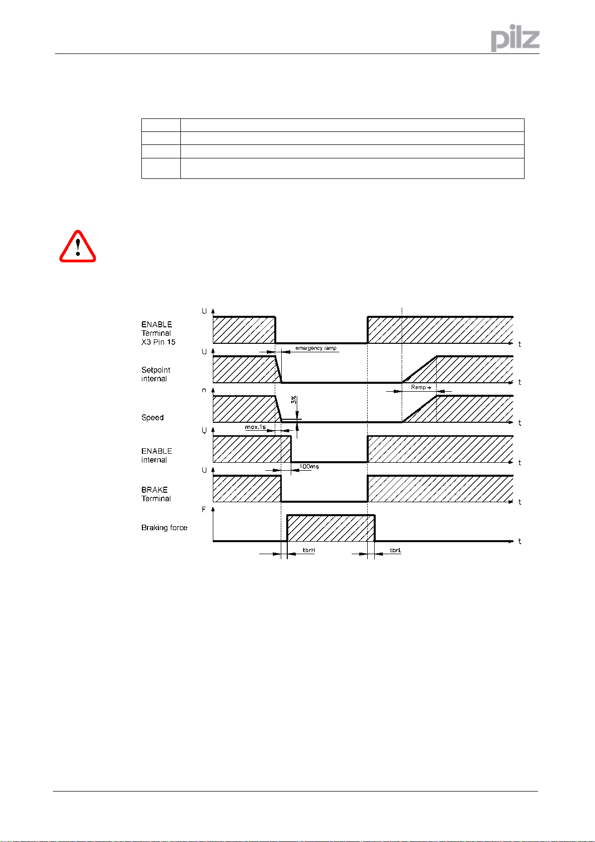
7.11 Control for motor-holding brake
A 24V / max. 2A holding brake in the motor can be controlled directly by the PMCprimo Drive2.
This function does not ensure personnel safety! (s. Option –AS- page 28)
The brake function must be enabled through the setup software PDRIVE with the parameter
„brake“.
In the diagram below you can see the time and functional relationships between the ENABLE
signal, speed setpoint, speed and braking force.
Installation manual PMCprimo Drive2
Artisan Technology Group - Quality Instrumentation ... Guaranteed | (888) 88-SOURCE | www.artisantg.com
Page 23
Page 25

During the internal ENABLE delay time of 100ms the speed setpoint of the PMCprimo Drive2 is
internally driven down a 10ms ramp to 0V. The brake output is switched on when 3% of the final
speed is reached. The rise (fbrH) and fall (fbrL) times of the holding brake which is built into the
motors are different for the various types of motor (see motor manual). A description of the interface
can be found on page 49.
A safe (for personnel) operation of the holding brake requires an additional “make” (n.o.) contact in
the brake circuit and a suppressor device (varistor) for the recommended brake circuit diagram
7 General
Page 24
Installation manual PMCprimo Drive2
Artisan Technology Group - Quality Instrumentation ... Guaranteed | (888) 88-SOURCE | www.artisantg.com
Page 26

7 General
7.12 Regen circuit
During braking with the aid of the motor, energy is fed back to the PMCprimo Drive2. This energy is
converted into heat in the regen resistor. The regen circuit (thresholds) are adjusted to the supply
voltage with the help of the setup software PDRIVE.
Our applications department can help you with the calculation of the regen power which is required.
A description of the interface can be found on page 50 .
Internal regen resistor: PMCprimo Drive2 sz. 01/03 66 Ohm
PMCprimo Drive2 sz. 06-20 33 Ohm
External regen resistor: PMCprimo Drive2 sz. 01-20 33 Ohm
Functional description:
1. Individual amplifiers, not coupled through the DC-link (DC+, DC-)
The circuit starts to respond at a DC-link voltage of 400V, 720V or 840V (depending on the supply
voltage). If the energy which is fed back from the motor, as an average over time or as a peak
value, is higher than the preset regen power, then the PMCprimo Drive2 will output the status
“regen power exceeded” and the regen circuit will be switched off. At the next internal check of the
DC-link voltage (after a few ms) an overvoltage will be detected and the PMCprimo Drive2 will be
switched off with the error message “Overvoltage” (⇒ page 82).
BTB/RTO contact (terminal X3, Pin2+3) will be opened at the same time (⇒page 64)
2. Several servo amplifiers coupled through the DC-link circuit (DC+, DC-)
Thanks to the built-in regen circuit with its patented w-characteristic, several amplifiers (even with
different current ratings) can be operated off a common DC-link, if they have a common supply
voltage. This is achieved by an automatic adjustment of the regen thresholds (which vary, because
of tolerances). The regen energy is distributed equally among all the amplifiers. The combined
power of all the amplifiers is always available, as continuous or peak power. The switch-off takes
place as described under 1. (above) for the PMCprimo Drive2 with the lowest switch-off threshold
(resulting from tolerances). The RTO (BTB) contact of this amplifier (terminals X3, Pin2+3) will be
opened at the same time (⇒ S. 64).
Regen circuit: technical data
Supply voltage
3 x 230 V Upper switch-on level of regen circuit V 400 – 430
Switch-off level of regen circuit V 380 – 410
Continuous power of regen circuit (RBint) W 80 200
Continuous power of regen circuit (RBext) max. kW 0,25 0,75
Pulse power, internal (RBint max. 1s) kW 2,5 5
Pulse power, external (RBext max. 1s) kW 5
3 x 400 V Upper switch-on level of regen circuit V 720 – 750
Switch-off level of regen circuit V 680 – 710
Continuous power of regen circuit (RBint) W 80 200
Continuous power of regen circuit (RBext) max. kW 0,4 1,2
Pulse power, internal (RBint max. 1s) kW 8 16
Pulse power, external (RBext max. 1s) kW 16
3 x 480 V Upper switch-on level of regen circuit V 840 – 870
Switch-off level of regen circuit V 800 – 830
Continuous power of regen circuit (RBint) W 80 200
Continuous power of regen circuit (RBext) max. kW 0,5 1,5
Pulse power, internal (RBint max. 1s) kW 10,5 21
Pulse power, external (RBext max. 1s) kW 21
Rated data
PMCprimo Drive2
DIM 01 - 03 06 - 20
Installation manual PMCprimo Drive2
Artisan Technology Group - Quality Instrumentation ... Guaranteed | (888) 88-SOURCE | www.artisantg.com
Page 25
Page 27
7 General
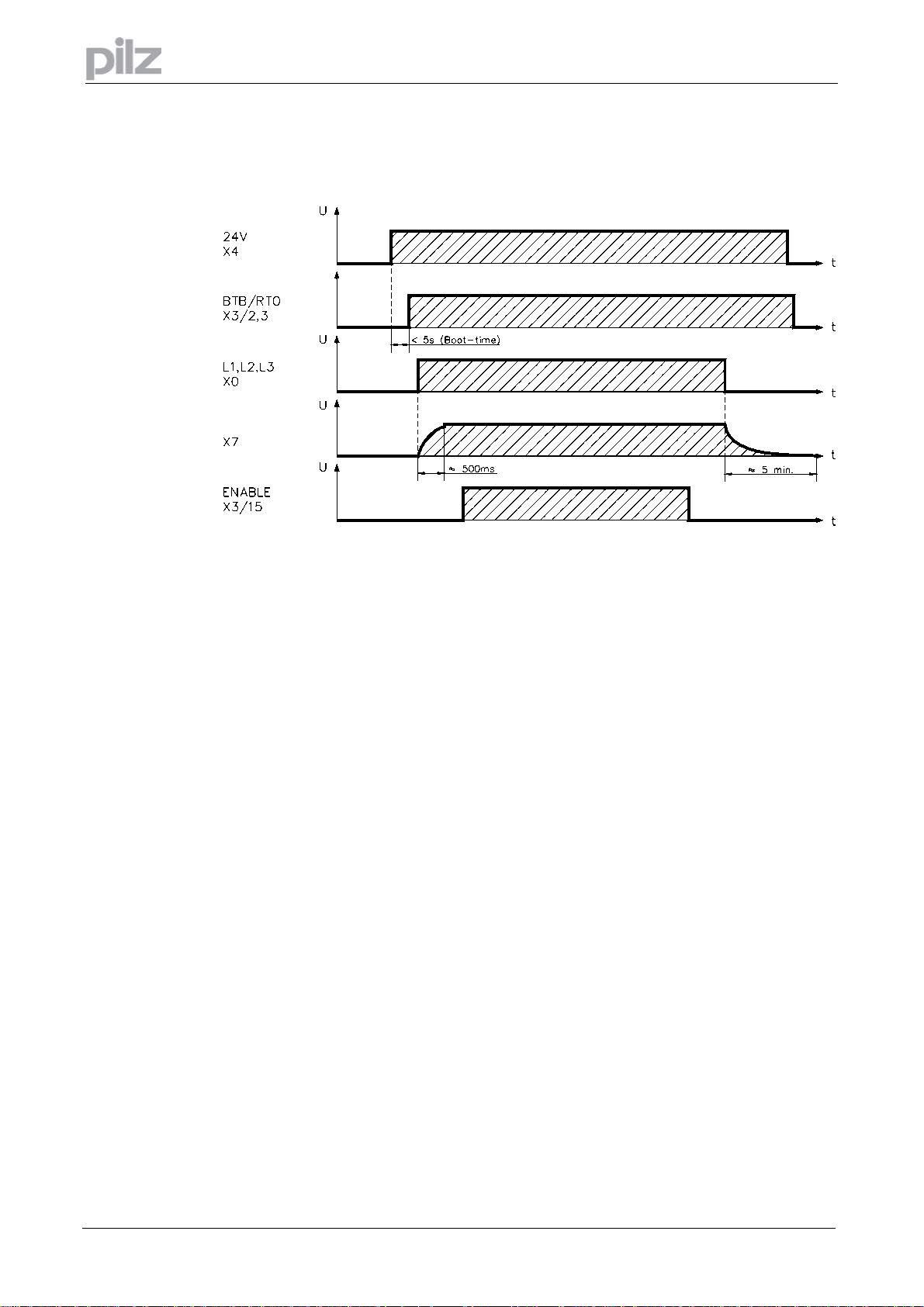
7.13 Switch-on and switch-off behaviour
The diagram below illustrates the correct functional sequence for switching the PMCprimo Drive2
on and off.
7.13.1 Stop function to EN 60204 (VDE 0113)
If a fault occurs (⇒ S. 81) ) the output stage of the PMCprimo Drive2 is switched off and the
BTB/RTO contact is opened. Instruments which are equipped with a selected “Brake” function use
a special sequence for switching off the output stage (⇒ S. 49).
The -AS- option can be used to switch off the drive via a positive-action (BG-approved) safety relay,
so that personnel safety is ensured at the drive shaft.
The stop functions are defined in EN 60204 (VDE 0113), Para. 9.2.2, 9.2.5.3.
There are three categories of stop functions:
Category 0: Shut down by immediately switching off the supply of energy to the drive
machinery (i.e. an uncontrolled shut-down);
Category 1: A controlled shut-down, during which the supply of energy to the drive
machinery is maintained to perform the shut-down, and where the energy
supply is only interrupted when the shut-down has been completed;
Category 2: A controlled shut-down, where the supply of energy to the drive machinery
is maintained.
Every machine must be equipped with a stop function to Category 0. Stop functions to Categories 1
and/or 2 must be provided if the safety or functional requirements of the machine make this
necessary.
Page 26
Installation manual PMCprimo Drive2
Artisan Technology Group - Quality Instrumentation ... Guaranteed | (888) 88-SOURCE | www.artisantg.com
Page 28

7 General
7.13.2 Emergency Stop strategies
The Emergency Stop function is defined in EN 60204 (VDE 0113), Para. 9.2.5.4.
You can find wiring recommendations in our application note “Stop and Emergency Stop
functions with PMCtendo DD4”.
7.13.2.1 Category 0
The controller is switched to “disable”, the electrical supply (400VAC) is disconnected. The drive
must be held by an electromagnetic holding device (brake).
In multiaxis systems with connected DC-link bus (intermediate circuit) the motor leads have to be
disconnected by a changeover switch (contactor, e.g. Siemens 3RT1516-1BB40) and shortcircuited
by resistors connected in a star configuration
7.13.2.2 Category 1
If hazardous conditions can result from an emergency stop switch-off with an unbraked rundown,
then the drive can be switched off by a controlled shut-down.
Stop Category 1 permits electromotive braking with a switch-off when zero speed has been
reached.
Safe shutdown can be achieved, when the loss of the mains supply is not rated as a fault and the
control takes over the disabling of the PMCprimo Drive2.
In the normal situation, only the supply power is switched off in a safe manner.
The 24V auxiliary supply remains switched on.
Installation manual PMCprimo Drive2
Artisan Technology Group - Quality Instrumentation ... Guaranteed | (888) 88-SOURCE | www.artisantg.com
Page 27
Page 29

7 General
7.14 Option -AS
7.14.1 General
A frequently required application task is the protection of personnel against the restarting of drives.
This can not be achieved by an electronic inhibit, but must be implemented with mechanical
elements (positively driven relay contacts).
To get round this problem, up to now either the main contactor in the mains supply line was
switched off, or another contactor was used to disconnect the motor from the PMCprimo Drive2.
The disadvantages of this method are:
• the DC-link has to be charged up again at restart
• wear on the contacts of the contactors, caused by switching under load
• extensive wiring required, with additional switching components
The -AS- option avoids these disadvantages. A safety relay in the servo amplifier is activated either
by the PLC or manually. Positively driven contacts provide a safe disconnection of the PMCprimo
Drive2, the setpoint input of the PMCprimo Drive2 is inhibited, and a signal is sent to the safety.
The advantages of the Option -AS-:
• the DC-link remains charged up, since the mains supply line remains active
• only low voltages are switched, so there is no contact wear
• very little wiring is required
• the functionality and the personnel safety when using the circuit recommendations in this
documentation have been approved by the trade liability association
7.14.2 Prescribed use
The -AS- restart lock is exclusively intended to provide safety for personnel, by preventing the
restart of a system.
To achieve this personnel safety, the wiring of the safety circuits must meet the safety requirements
of EN60204, EN292 and VDI 2853.
The -AS- restart lock must only be activated,
• when the motor is no longer rotating (speed = 0 rpm).
Drives with a suspended load must have an additional safe mechanical blocking (e.g. by a
motor-holding brake).
• when the monitoring contacts (KSO1/2 and BTB/RTO) for all PMCprimo Drives are wired into
the control signal loop (to recognize a cable break).
The -AS- restart lock may only be controlled by a CNC if the control of the internal safety relay is
arranged for redundant monitoring
The -AS- restart lock must not be used if the drive is to be made inactive for the following reasons:
1. - cleaning, maintenance and repair operations
- long inoperative periods
In such cases, the entire system should be disconnected from the supply by the personnel,
and secured (main switch).)
2. - emergency-stop situations
In an emergency-stop situation, the main contactor is switched off (by the emergency-stop
button or the BTB-contact in the safety circuit).)
Page 28
Installation manual PMCprimo Drive2
Artisan Technology Group - Quality Instrumentation ... Guaranteed | (888) 88-SOURCE | www.artisantg.com
Page 30
7 General
7.14.3 Functional description
An additional connector (X12) is mounted on the front panel of the PMCprimo Drive2. The coil
connections and a make (n.o.) contact of a safety relay are made available through 4 terminals on
this connector.
The 24V DC safety relay in the servo amplifier (TÜV approved) is controlled externally. All the relay
contacts have positive action.
Two contacts switch off the driver supply of the output stage in the PMCprimo Drive2, and short the
internal setpoint signal to AGND (0 V).
The make (n.o.) contact used for monitoring is looped into the control circuit.
If the safety relay is not energized, then the monitoring contact is open and the PMCprimo Drive2 is
ready for operation.
If the drive is electronically braked, the PMCprimo Drive2 is disabled and the motor-holding brake is
on, then the safety relay is energized (manually or by the controls).
The supply voltage for the driver circuit of the output stage is switched off in a safe manner, the
internal setpoint is shorted to 0V, and the monitoring contact bridges the safety logic in the control
circuit of the system (monitoring of protective doors etc.)
Even if the output stage or driver is destroyed, it is impossible to start the motor.
If the safety relay itself is faulty, then the monitoring contact cannot bridge the safety logic of the
system. Opening the protective devices will then switch off the system.
Installation manual PMCprimo Drive2
Artisan Technology Group - Quality Instrumentation ... Guaranteed | (888) 88-SOURCE | www.artisantg.com
Page 29
Page 31

7 General
7.14.4 Block diagram
7.14.5 Signal diagram
Page 30
Installation manual PMCprimo Drive2
Artisan Technology Group - Quality Instrumentation ... Guaranteed | (888) 88-SOURCE | www.artisantg.com
Page 32

7 General
7.14.6 Installation and Commissioning
7.14.6.1 Safety instructions
• Observe "Use as directed" on page 11.
• The monitoring contacts (KSO1/2) for each PMCprimo Drive2 with an -AS- option must be
looped into the control circuit. This is vital, so that a malfunction of the internal safety relay or a
cable break can be recognized.
• If the -AS- option is automatically activiated by a control system (KSI1/2), then make sure that
the output of the control is monitored for possible malfunction. This can be used to prevent a
faulty output from activating the -AS- option while the motor is running.
7.14.6.2 Application example
The following application example describes the function of the –AS- option. A PLC is controlling
the function:
1. The PLC sets the signal „activate AS“ with a digital output to a digital input of the PMCprimo
Drive2
2. The PMCprimo Drive2 triggers a program which stops the motor and goes in the motor-off
state (MO).
3. The ENABLE-signal (X3/pin 15) has to go low (0V).
4. The motor brake is activated from the PMCprimo Drive2
5. Now another PMCprimo Drive2 program sets an output and activates the option –AS
6. The PLC will get the message „AS activated“ via the monitoring contacts KSO1/2
If the PLC doesn’t gets the message „AS activated“ after setting „activate –AS“ to PMCprimo Drive2
there is a malfunction in the system.
The master contactor should be opened in this case.
7.14.6.3 Connection diagram
Installation manual PMCprimo Drive2
Artisan Technology Group - Quality Instrumentation ... Guaranteed | (888) 88-SOURCE | www.artisantg.com
Page 31
Page 33

8 Installation
8 Installation
8.1 Important instructions
• Protect the PMCprimo Drive2 from impermissible stresses. In particular, do not let any
components become bent or any insulation distances altered during transport and handling.
Avoid contact with electronic components and contacts.
• Check the combination of PMCprimo Drive2 and motor. Compare the rated voltage and current
of the units. Carry out the wiring according to the connection diagram on page 31.
• Make sure that the maximum permissible rated voltage at the terminals L1, L2, L3 or +DC,
–DC is not exceeded by more than 10% even in the most unfavourable case (see EN 60204-1
Section 4.3.1). An excessive voltage on these terminals can lead to destruction of the regen
circuit and the PMCprimo Drive2.
Use the PMCprimo Drive2 only on an earthed 3-phased supply system, to drive a synchronous
servomotor of the PMCtendo AC1 or PMCtendo AC2 series.
• The fusing of the AC supply input and the 24V supply is installed by the user (⇒ page 21).
• Take care that the PMCprimo Drive2 and motor are earthed properly. Do not use painted (non-
conductive) mounting plates.
• Route power and control cables separately. We recommend a separation of at least 20 cm.
This improves the interference immunity required by EMC regulations. If a motor power cable
is used which includes cores for brake control, the brake control cores must be separately
shielded. Earth the shielding at both ends (⇒ page 49).
• Install all heavy-current cables with an adequate cross-section, as per EN 60204.
• Wire the BTB/RTO contact in series into the safety circuit of the installation. Only in this way is
the monitoring of the PMCprimo Drive2 assured.
• Install all shielding with large areas (low impedance), with metallized connector housings or
shield connection clamps where possible.
• Ensure that there is an adequate flow of cool, filtered air into the bottom of the switchgear
cabinet. See page 21.
• It is permissible to alter the PMCprimo Drive2 settings by using the setup software.
Any other alterations will invalidate the warranty.
Caution
Never disconnect the electrical connections to the PMCprimo Drive2 while it is live. In un-
favourable circumstances this could result in destruction of the electronics.
Residual charges in the capacitors can have dangerous levels up to 300 seconds after
switching off the mains supply voltage. Measure the bus voltage at the DC-link pins (+DC/-
DC), and wait until the voltage has fallen below 40V.
Control and power connections can still be live, even when the motor is not rotating.
Page 32
Installation manual PMCprimo Drive2
Artisan Technology Group - Quality Instrumentation ... Guaranteed | (888) 88-SOURCE | www.artisantg.com
Page 34

8 Installation
8.2 Assembly
Material: 2 or 4 hexagon socket screws to DIN 912, M5
Tool required: 4 mm Allen key
Installation manual PMCprimo Drive2
Artisan Technology Group - Quality Instrumentation ... Guaranteed | (888) 88-SOURCE | www.artisantg.com
Page 33
Page 35

8 Installation
8.3 Dimensions
Page 34
Installation manual PMCprimo Drive2
Artisan Technology Group - Quality Instrumentation ... Guaranteed | (888) 88-SOURCE | www.artisantg.com
Page 36

8 Installation
-
8.4 Wiring
Only professional staff who are qualified in electrical engineering are allowed to install the
PMCprimo Drive2.
The installation procedure is described as an example. A different procedure may be sensible or
necessary, depending on the application of the equipment.
Caution !
Only install and wire up the equipment when it is not live, i.e. when neither the mains
power supply nor the 24 V auxiliary voltage nor the operating voltages of any other
connected equipment is switched on.
Take care that the cabinet is safely disconnected (with a lock-out, warning signs etc.).
The individual voltages will be switched on for the first time during commissioning.
Note !
The ground symbol ;, which you will find in all the wiring diagrams, indicates that
you must take care to provide an electrically conductive connection with the largest
possible area between the unit indicated and the mounting plate in the switchgear cabinet.
This connection is for the effective grounding of HF interference, and must not be confused
with the PE- symbol : (a protective measure to EN 60204).
Use the following connection diagrams:
— Power and control connections: page 37
— Resolver: page 52
— HIPERFACE encoder: page 53
— Encoder emulation ROD: page 54
— Encoder emulation SSI: page 55
— RS232 / PC: page 56
— Power supply: page 45
— Digital signals: page 59
— Analog signals: page 65
— Master encoder: page 69
— Panel/Profibus: page 74
— CAN bus: page 67
Installation manual PMCprimo Drive2
Artisan Technology Group - Quality Instrumentation ... Guaranteed | (888) 88-SOURCE | www.artisantg.com
Page 35
Page 37

g
The following notes should assist you to carry out the installation in a sensible sequence, without
overlooking anything important.
In a closed switchgear cabinet. Observe page 21 .
The site must be free from conductive or corrosive
ma materials.
For the mounting position in the cabinet ⇒ page 33
Assemble the PMCprimo Drive2 and power supply close
together on the conductive, earthed mounting plate in the
cabinet.
Select cables according to EN 60204 ⇒ page 22.
Site
Ventilation
Assembly
Cable selection
Check that the ventilation of the PMCprimo Drive2 is
unimpeded and keep within the permitted ambient
temperature ventilation ⇒ page 21.
Keep the required space clear above and below the
PMCprimo Drive2 ⇒ page 33.
8 Installation
EMC-compliant shielding and grounding (⇒ page 86).
Earth the mounting plate, motor housing and CNC-GND
of the controls.
Grounding
Shieldin
Wiring
— Route power leads and control cables separately.
— Wire the BTB/RTO contact in series into the
safety loop of the installation.
— Connect the digital control inputs to the PMCprimo
Drive2.
— Connect up AGND.
— Connect the analog signals, if required.
— Connect up the feedback unit (resolver or
HIPERFACE encoder).
— Connect the input and output signals.
— Connect the motor leads.
Connect shielding to EMC connectors at both ends
Use motor choke on length >25m (MD400)
— Connect motor-holding brake, connect shielding to
EMC connectors at both ends.
— If required, connect the external regen resistor (with
fusing.
— Connect aux. supply (24 V).
(for max. permissible voltage values⇒ page 20)
— Connect main power supply.
(for max. permissible voltage values⇒ page 20)
Page 36
— Connect PC (⇒ page 80).
Final check
— Final check of the implementation of the wiring,
according to the wiring diagrams which have been
used.
Installation manual PMCprimo Drive2
Artisan Technology Group - Quality Instrumentation ... Guaranteed | (888) 88-SOURCE | www.artisantg.com
Page 38

8 Installation
8.4.1 Connection diagram PMCprimo Drive2 - part 1
Installation manual PMCprimo Drive2
Artisan Technology Group - Quality Instrumentation ... Guaranteed | (888) 88-SOURCE | www.artisantg.com
Page 37
Page 39

8 Installation
8.4.2 Connection diagram PMCprimo Drive2- part 2
Page 38
Installation manual PMCprimo Drive2
Artisan Technology Group - Quality Instrumentation ... Guaranteed | (888) 88-SOURCE | www.artisantg.com
Page 40

8 Installation
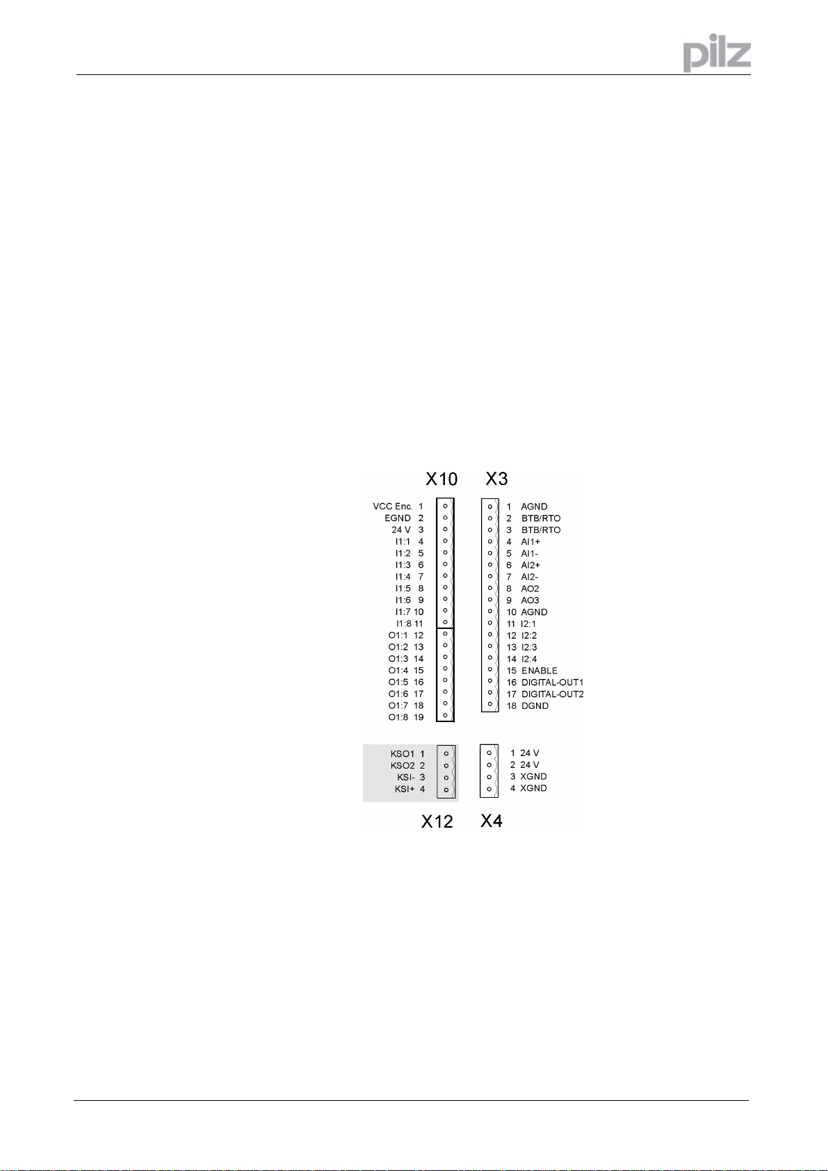
8.4.3 Pin assignments overview
Installation manual PMCprimo Drive2
Artisan Technology Group - Quality Instrumentation ... Guaranteed | (888) 88-SOURCE | www.artisantg.com
Page 39
Page 41

8 Installation
8.4.4 Pin assignments - details
Page 40
Installation manual PMCprimo Drive2
Artisan Technology Group - Quality Instrumentation ... Guaranteed | (888) 88-SOURCE | www.artisantg.com
Page 42

8 Installation
8.4.5 Pin assignments Modbus/Profibus
Note: It is not possible to use Modbus and Profibus the same time. For usage an adapter cable is
needed.
RJ 45
Note: Adapter cable RJ45 D-Sub9 is available.
RJ 45 Signal
Modbus
1 GND DP-GND 5
2 9
3 4
4 /RxD DP- 8
5 RxD DP+ 3
6 /TxD 7
7 TxD 2
8 5V/100mA 6
- 1
Signal
Profibus
D-Sub9
Installation manual PMCprimo Drive2
Artisan Technology Group - Quality Instrumentation ... Guaranteed | (888) 88-SOURCE | www.artisantg.com
Page 41
Page 43

8 Installation
8.4.6 Notes on connection techniques
Shielding connection to the front panel:
Remove the outer covering of the
cable and the shielding braid from
the cores for the required length.
Secure the cores with a cable tie.
Remove the outer covering of the
cable over a length of about
30mm, without damaging the
shielding braid.
Pull a cable tie through the slot in
the shielding rail (front panel) of
the PMCprimo Drive2.
Use the cable tie to clamp the
shielding braid of the cable firmly
to the shielding rail.
Page 42
Installation manual PMCprimo Drive2
Artisan Technology Group - Quality Instrumentation ... Guaranteed | (888) 88-SOURCE | www.artisantg.com
Page 44

8 Installation
8.5 Key operation for parameter setting
8.5.1 Comparison to the key operation with PMCtendo DD4
The key operation for PMCprimo Drive2 is like the key operation for PMCtendo DD4 (see
installation manual for PMCtendo DD4). This means that the two keys are used in the same way
and also the menus are named similarly.
8.5.2 Basic key operation
The two keys can be used to perform the following functions:
Key symbol Functions
press once: go up one menu item, increase number by one
press twice in rapid succession: increase number by ten
press once: go down one menu item, decrease number by one
press twice in rapid succession: decrease number by ten
Press and hold right key, then press left key as well:
enter a number, return function name
8.5.3 Menu operation
For accessing the menu press the right key while switching on the 24 V power supply. Then
this parameters can be set with the menu:
• The operating mode
(0: Standalone, 2 Node and 3 Host+Node)
When changing the operate mode between 2 and 3 then the application program in the
flash memory is not erased. The memory is even not erased if mode 0 is selected by a
mistake.
• The CAN node number depending from the operating mode:
Standalone: from 1 to 127
Node: from 1 to 60
Host+Node: Not available because node number is fixed
• The CAN baud rate. For similar settings as for the PMCtendo DD4 only two settings are
supported: 7 (500Kbit/s) and 10 (1Mbit/s). The other baud rates as for the PMCtendo DD4
(0 to 6 and 8 to 9) are not available
• The proportional Gain Kp (GV command) for the velocity loop of the drive.
• Save parameters.
After changing the parameter and returning from the function the changed parameter have
to be saved with the menu for saving. Then the system has to be switched off and on to
enable the changed settings.
Installation manual PMCprimo Drive2
Artisan Technology Group - Quality Instrumentation ... Guaranteed | (888) 88-SOURCE | www.artisantg.com
Page 43
Page 45

8 Installation
8.5.4 LED Display
The LED display will show the menu for changing the parameters:
Operating mode
CAN node number
Baud rate
KP speed control
to
to
to
to
to
to
Save parameters in Flash
8.5.5 Automatic detection in PMCprimo
For automatic detection of a new drive no special change in the firmware is necessary.
Inside the autostart sequence it is determined if a new drive is in the cabinet.
This can be done for example with reading the serial number of the drive.
Example:
AS AUTOSTART
ES AUTOSTART
CH0.1
$SER1="SERIALNO"
IF($SER1!=$SER1ACTUAL);XS DRIVE_0;$SER1ACTUAL=$SER1;SP2
NS
The sequence gets the actual serial number and compares it with the last saved number. If there is
a difference then it calls the drive sequence which adjusts all parameters. Then it stores the new
serial number. Therefore the drive parameters are stored only once.
Page 44
Installation manual PMCprimo Drive2
Artisan Technology Group - Quality Instrumentation ... Guaranteed | (888) 88-SOURCE | www.artisantg.com
Page 46

9 Interfaces
9 Interfaces
All important interfaces of the PMCprimo Drive2 are shown in this chapter. The precise location of
the connectors and terminals can be seen on page 39.
9.1 Power supply
9.1.1 Mains supply (X0)
• Direct to earthed 3~ supply, 230V
• Fusing (e.g. fusible cut-outs) provided by the user ⇒ page 21
• For single phase operation use L1 and L2!
-10%
... 480V
+10%,
50 ... 60 Hz, integrated filter
Installation manual PMCprimo Drive2
Artisan Technology Group - Quality Instrumentation ... Guaranteed | (888) 88-SOURCE | www.artisantg.com
Page 45
Page 47

9 Interfaces
9.1.2 24V-auxiliary supply (X4)
• Electrically isolated, external 24V DC supply, e.g. with insulating transformer
• Required current rating⇒ page 20
• Integrated EMC filter for the 24V auxiliary supply
• See important notes to commissioning ⇒ page 78
Page 46
Installation manual PMCprimo Drive2
Artisan Technology Group - Quality Instrumentation ... Guaranteed | (888) 88-SOURCE | www.artisantg.com
Page 48

9 Interfaces
9.1.3 24V-Supply (X10)
• Electrically isolated, external 24V DC supply, e.g. with insulating transformer
• You can take 24 V from terminal X4
• Required current rating ⇒ page 20
• See important notes to commissioning ⇒ page 78
Installation manual PMCprimo Drive2
Artisan Technology Group - Quality Instrumentation ... Guaranteed | (888) 88-SOURCE | www.artisantg.com
Page 47
Page 49

9 Interfaces
9.1.4 Master encoder supply (X10)
• Common power supply for all connected encoders
• Voltage range: See encoder datasheet
• Reference ground is EGND
• External fusing provided by the user
Page 48
Installation manual PMCprimo Drive2
Artisan Technology Group - Quality Instrumentation ... Guaranteed | (888) 88-SOURCE | www.artisantg.com
Page 50

9 Interfaces
9.1.5 DC-link (X7)
Can be connected in parallel. A patented circuit distributes the regen power among all the
amplifiers connected to the same DC-link circuit
9.2 Motor connection with brake (X9)
9.2.1 Lead length < 25m
Installation manual PMCprimo Drive2
Artisan Technology Group - Quality Instrumentation ... Guaranteed | (888) 88-SOURCE | www.artisantg.com
Page 49
Page 51

9 Interfaces
9.2.2 Lead length > 25m
For lead lengths above 25m the choke box MD400 must be wired into the motor lead, close to the
PMCprimo Drive2.
Page 50
Installation manual PMCprimo Drive2
Artisan Technology Group - Quality Instrumentation ... Guaranteed | (888) 88-SOURCE | www.artisantg.com
Page 52

9 Interfaces
9.3 External regen resistor (X8)
Remove the plug-in link between the terminals X8, Pin 1 (-RB) and X8, Pin 2 (+Rbint).
Installation manual PMCprimo Drive2
Artisan Technology Group - Quality Instrumentation ... Guaranteed | (888) 88-SOURCE | www.artisantg.com
Page 51
Page 53

9 Interfaces
9.4 Feedback
9.4.1 Resolver connection (X2)
The motors of the PMCtendo AC1 and PMCtendo AC2 series have 2-pole hollow-shaft resolvers
built in as a standard. It is possible to connect 2...36-pole resolvers to the PMCprimo Drive2.
If lead lengths of more than 100m are planned, please contact our application department. The
thermostat contact in the motor is connected via the resolver cable to the PMCprimo Drive2 and
evaluated there.
Page 52
Installation manual PMCprimo Drive2
Artisan Technology Group - Quality Instrumentation ... Guaranteed | (888) 88-SOURCE | www.artisantg.com
Page 54

9 Interfaces
9.4.2 HIPERFACE Encoder (X1)
As an option, the motors can be fitted with a single-turn or multiturn sine-cosine encoder
(HIPERFACE).
This encoder is used by the PMCprimo Drive2 as a feedback device for drive tasks which require
highly precise positioning or extremely smooth running.
If lead lengths of more than 50m are planned, please consult our applications department.
The thermostat contact in the motor is connected via the encoder cable to the PMCprimo Drive2
and evaluated there.
Installation manual PMCprimo Drive2
Artisan Technology Group - Quality Instrumentation ... Guaranteed | (888) 88-SOURCE | www.artisantg.com
Page 53
Page 55

9 Interfaces
9.5 Encoder emulations
The encoder emulations are normally not used. Nevertheless there are applications which use this
emulations (e.g. linking the actual position to another PMCprimo Drive2 on channel 2.
9.5.1 Incremental encoder emulation ROD (X5)
The incremental-encoder interface is part of the package supplied. In the PMCprimo Drive2, the
position of the motor shaft is calculated from the cyclic-absolute signals of the resolver or
HIPERFACE encoder.
Incremental-encoder compatible pulses are generated from this information.
You can change the resolution with the parameter „Resolution“ (s. setup software PDRIVE, window
„Encoder“ ):
Resolution encoder Feddback system
256/512/1024 Resolver
2048/4096 HIPERFACE
8192 HIPERFACE up to 3000 rpm
16384 HIPERFACE up to 1500 rpm
You can also adjust and store the position of the zero pulse within one mechanical turn (parameter
„NI-Offset“, window „Encoder“ in PDRIVE ). Because of the compatibility with normal commercial
pulse encoders, you can only set the zero pulse when A=B=1.
The drivers are supplied from an internal supply voltage.
9.5.2 Application example
Page 54
Installation manual PMCprimo Drive2
Artisan Technology Group - Quality Instrumentation ... Guaranteed | (888) 88-SOURCE | www.artisantg.com
Page 56

9 Interfaces
9.5.3 SSI emulation (X5)
The SSI interface (synchronous serial absolute-encoder emulation) is part of the delivered package,
too.
In the PMCprimo Drive2, the position of the motor shaft is calculated from the cyclic-absolute
signals of the resolver or HIPERFACE encoder. A position output is generated from this
information, compatible with the data format of normal commercial SSI absolute encoders. This
synchronous, serial, cyclic-absolute 12-bit (singleturn) or 24-bit (multiturn) information is output on
the SUB-D-Connector X5.
The signal sequence can be output in Gray code (standard) or in binary code (Parameter „SSICode“, window „Encoder“ in PDRIVE ).
A serial signal is read out from the control, with a synchronous clock frequency of max. 1.5 MHz.
The servo amplifier can be adjusted to the clock frequency of your SSI-evaluation with the SSICLOCK parameter (200 kHz or 1.5MHz and inverted).
The drivers are supplied from an internal supply voltage.
9.5.4 Application example
The count direction for the SSI interface is upwards when the motor shaft is rotating clockwise
(looking at the shaft end).
Installation manual PMCprimo Drive2
Artisan Technology Group - Quality Instrumentation ... Guaranteed | (888) 88-SOURCE | www.artisantg.com
Page 55
Page 57

9 Interfaces
9.6 RS232 interface, PC interface (X6)
9.6.1 General
The programming of the PMCprimo Drive2 is very easy with the setup software PMCprimo Motion
Control Tools on a Personal Computer (PC).
PDrive and PTerm are part of the PMCprimo Motion Control Tools on the supplied CD-ROM.
Connect the PC interface (X6) of the servo amplifier via a normal commercial 3-core null-modem
cable to a serial interface on the PC. You can select the port (COM1 or COM2) with the setup
software.
Further details can be found in the software manual for PDrive and PTerm.
The interface is electrically isolated through an optocoupler.
Page 56
Installation manual PMCprimo Drive2
Artisan Technology Group - Quality Instrumentation ... Guaranteed | (888) 88-SOURCE | www.artisantg.com
Page 58

9 Interfaces
9.6.2 Pin assignment of the null-modem cable
View:
Looking at the face of the built-in SUB-D connectors, this corresponds to the solder side of the
SUB-D sockets on the cable.
Caution!
Do not connect more cores than shown: X6 (Pin 2,3,5)!
The interface may be damaged!
Installation manual PMCprimo Drive2
Artisan Technology Group - Quality Instrumentation ... Guaranteed | (888) 88-SOURCE | www.artisantg.com
Page 57
Page 59

Connection via RS232
The following parameters are used (standard):
• 9600 Baud
• 8 data bits
• 1 stop bit
• No parity
• XOn/XOff-Software-Handshake
With the command BD the communication rate can be changed (see PMCprimo programming
manual).
Set these parameters with PTerm (see PTerm programming manual):
9 Interfaces
Page 58
After clicking on
the connection will be made and programming can be started.
Installation manual PMCprimo Drive2
Artisan Technology Group - Quality Instrumentation ... Guaranteed | (888) 88-SOURCE | www.artisantg.com
Page 60

9 Interfaces
9.7 Digital signals
9.7.1 Digital inputs I1:1 - I1:8 (X10)
All digital inputs are electrically isolated through optocouplers
• Reference ground is EGND (terminal X10, Pin 2)
• Logic is PLC compatible
• H-level: +11..24V / 10 mA
• L-level: 0 V .. 11 V/ 0 mA
• The inputs I1:1 to I1:4 are „fast“ inputs (< 1 us) for e.g. product referencing
• I1:1 and I1:2 will be additionally mapped to both inputs E2:7 and E2:8
Installation manual PMCprimo Drive2
Artisan Technology Group - Quality Instrumentation ... Guaranteed | (888) 88-SOURCE | www.artisantg.com
Page 59
Page 61

9 Interfaces
9.7.2 Digital inputs I2:1 - I2:4 (X3)
All digital inputs are electrically isolated through optocouplers
• Reference ground is DGND (terminal X3, Pin 18)
• Logic is PLC compatible
• H-level: +12 … 30V / 7mA
• L-level: 0 … 7V / 0 mA
Page 60
Installation manual PMCprimo Drive2
Artisan Technology Group - Quality Instrumentation ... Guaranteed | (888) 88-SOURCE | www.artisantg.com
Page 62

9 Interfaces
9.7.3 Digital ENABLE input (X3)
The output stage of the PMCprimo Drive2 is activated by the enable signal (terminal X3, Pin 15,
input 24V, active high).
In the inhibited state (low signal) the motor which is attached does not have any torque.
• Reference ground is digital-GND (DGND, terminal X3, Pin 18)
• Logic is PLC compatible
• H-level: +12 … 30V / 7 mA
• L-level: 0 … 7V / 0 mA
• The digital input is electrically isolated through optocoupler
Installation manual PMCprimo Drive2
Artisan Technology Group - Quality Instrumentation ... Guaranteed | (888) 88-SOURCE | www.artisantg.com
Page 61
Page 63

9 Interfaces
9.7.4 Digital outputs O1:1 - O1:8 (X10)
• Reference ground is EGND (terminal X10, Pin 3)
• All digital outputs are electrically isolated and shortcircuit protected
• „high-side“-outputs: 24V /0,1 A each output
Page 62
Installation manual PMCprimo Drive2
Artisan Technology Group - Quality Instrumentation ... Guaranteed | (888) 88-SOURCE | www.artisantg.com
Page 64

9 Interfaces
9.7.5 Digital outputs Digital-Out 1+2 (X3)
• Reference ground is DGND (terminal X3, Pin 18)
• All digital outputs are electrically isolated
• „Open-Collector“-outputs: 24V /10 mA each output
The both digital outputs DIGITAL-OUT 1+2 can not be used with the PMCprimo programming
language.
But you can select with PDrive, screen window “I/O Digital“, a predefined output function ,
e.g. „regen resistor threshold exceeded“.
More information can be found in the PDrive user manual.
Installation manual PMCprimo Drive2
Artisan Technology Group - Quality Instrumentation ... Guaranteed | (888) 88-SOURCE | www.artisantg.com
Page 63
Page 65

9 Interfaces
9.7.6 Relay output (X3)
• BTB/RTO: Relay output, max. 30V DC or 42V AC, 0.5A
• Ready-to-operate contact NO (Terminal X3, Pin 2 and X3, Pin 3 )
Operational readiness (terminals X3, Pin 2 and X3, Pin 3 ) is signalled by a floating relay contact.
The contact is closed when the servo amplifier is ready for operation, the signal is not influenced by
the enable signal, the I²t- limit, or the regen threshold.
Faults with error number xF20 or higher cause the BTB/RTO contact to open and the switch
off of the output stage.
A list of the error messages can be found on page 81.
Page 64
Installation manual PMCprimo Drive2
Artisan Technology Group - Quality Instrumentation ... Guaranteed | (888) 88-SOURCE | www.artisantg.com
Page 66

9 Interfaces
9.8 Analog signals
9.8.1 Analog outputs AO2 and AO3 (X3)
• Reference ground is AGND (Terminal X3 Pin1 and X3 Pin10)
• Output resistance: 2,2 kΩ
• Output voltage range: ± 10 V
• Resolution: 10 Bit
Installation manual PMCprimo Drive2
Artisan Technology Group - Quality Instrumentation ... Guaranteed | (888) 88-SOURCE | www.artisantg.com
Page 65
Page 67

9 Interfaces
9.8.2 Analog inputs AI1 and AI2 (X3)
• Reference ground is AGND (Terminal X3 Pin1 and X3 Pin10)
• Input resistance: 20 kΩ
• Differential-input voltage max: ± 10 V
• Resolution AI1: 14 Bit
• Resolution AI2: 12 Bit
The analog inputs AI1 and AI2 are internal additionally mapped on the digital inputs E2:5 and E2:6.
If the value of the applied voltage is beyond 7,5 V, it will be regarded as HIGH-Signal. By this
means, there are two more digital inputs available, if needed.
Attention: The maximum permitted input voltage range may not be exceeded (±10V). See
page 20). The inputs are not divided gavalnic!
Page 66
Installation manual PMCprimo Drive2
Artisan Technology Group - Quality Instrumentation ... Guaranteed | (888) 88-SOURCE | www.artisantg.com
Page 68

9 Interfaces
9.9 CAN bus interface (X11/2 and X11/1)
9.9.1 General
With the CAN bus interfaces CAN-1B (X11/1) and CAN-1A (X11/2) multible PMCprimo-motion
control-systems can be connected together.
The bus speed is 500kBaud or 1Mbit/s.
Additional safety signals provide fault detection.
Much more details about connection systems via CAN are included in the manual „PMCprimo
CAN network“. The manual is part of the enclosed CD-ROM „PMCprimo Motion Control Tools“.
9.9.2 Connecting PMCprimo Drive2 systems
On each system CAN-1A (X11/2) and CAN-1B (X11/1) of the next system are joined together in the
way as shown below.
Installation manual PMCprimo Drive2
Artisan Technology Group - Quality Instrumentation ... Guaranteed | (888) 88-SOURCE | www.artisantg.com
Page 67
Page 69

9 Interfaces
9.9.3 CAN bus cable
The interface cable is a 1:1 connection (9-pole SUB-D socket to 9-pole SUB-D plug).
• Characteristic impedance: 120 Ω
• Cable capacitance : max. 60 nF/km
• Lead resistance (loop):: 159,8 Ω/km
• Max. cable length : 70 m (1
st
to last node )
For EMC reasons, the SUB-D connector housing must fulfill the following conditions:
• metal or metallized housing provision for cable shielding connection in housing,
• large-area connection.
You have to terminate the first and the last node (120 Ω ).
9.9.4 Speciality 1st node
• The 1st node is supplied at CAN-1A (X11/2, Pin 9) with +12V , at Pin 3 CAN-GND (0V).
• Minimum power dissipation of the power supply unit: 1 VA each node.
• An additional resistor 10 kΩ (250 mW, metal 1%) between Pin 1 and Pin 4 is necessary.
9.9.5 Speciality last node
• The last node needs a jumper bridge (0 Ω) at CAN-1B between Pin 4 and Pin 9.
You can order pre-assembled cables with the following Art.No.:
Position Art.No
CAN bus cable (1:1) 250 mm 1803136
CAN bus cable (1:1) 700 mm 1803117
CAN feedlead 0802951
CAN termination 0802950
Power supply 12 V 4803002
9.9.6 Fault detection
The following faults will be detected:
• Missing or defect +12V-CAN power supply
• Malfunction of a bus node
• Break of the CAN bus cable
9.9.7 Connecting external CANopen bus devices
It is possible to connect external CANopen devices with PMCprimo-motion control-systems.
With e.g. a CAN-I/O module you can increase the number of inputs and outputs in the system.
A CANopen encoder or CANopen panel can also be used.
Much more examples and hints can be found on the manual „PMCprimo CAN network“ on the
enclosed CD-ROM.
Page 68
Installation manual PMCprimo Drive2
Artisan Technology Group - Quality Instrumentation ... Guaranteed | (888) 88-SOURCE | www.artisantg.com
Page 70

9 Interfaces
9.10 Master encoder interface / CAN2 (X11/4)
The PMCprimo Drive2 is designed for use with incremental or SSI encoders. The encoder type can
easily be changed with the FS command.
With SSI encoders the number of data bits can be set with NB.
The logical sense of each encoder input can be changed with the command CW. Setting the
direction bit reverses the direction of the encoder without wiring.
If a reference signal occurs, the actual encoder position is stored (see reference inputs page 59).
This is useful for product referencing. For further details see PMCprimo programming manual.
A master encoder is normally connected at the encoder input of channel 2. But with the FC
command the encoder signals can be redirected.
All encoders have a common power supply with connector X10 (Pin 1+2). See also page 48.
If encoders with different supply voltages should be connected, the encoder cables have to
be modified. The two wires for supply voltage are connected with an external power supply
(X11/4: Pin 4+9).
The input configuration is designed for 5 V logic level. Exceeding this range will damage the
input logic.
Installation manual PMCprimo Drive2
Artisan Technology Group - Quality Instrumentation ... Guaranteed | (888) 88-SOURCE | www.artisantg.com
Page 69
Page 71

9 Interfaces
9.10.1 CAN 2 interface
The interface X11/4 can be used, with the expansion board (page 88), as second
CAN interface (CAN-2).
With the used CANopen protocol, other CAN-Bus devices can be integrated in the network. You
can increase the number of inputs and outputs, with a CAN-I/O module. CANopen encoders or a
CANopen panel can be included also.
Pin Description
2CAN-L
3CAN-GND
7CAN-H
Note:
The termination (120 Ω) for CAN-2 is activated with a DIP-switch. For that switch the DIP-switch to
“ON”.
The 12 VDC feed is not necessary with this kind of networking. For wiring of the CAN bus, cables of
our standard delivery program can be used (see page 68).
Page 70
Installation manual PMCprimo Drive2
Artisan Technology Group - Quality Instrumentation ... Guaranteed | (888) 88-SOURCE | www.artisantg.com
Page 72

9 Interfaces
9.10.2 Jumper settings
A manual for installation of the PMCprimo-board is available.
ESD!
ESD : electrostatic discharge
ESDS : electrostatic sensitive devices
Motion control units contain electrostatic sensitive devices which will be damaged by
electrostatic discharge. Therefore servicing shall only be performed in ESD safe areas
and by ESD protected personnel.
Installation manual PMCprimo Drive2
Artisan Technology Group - Quality Instrumentation ... Guaranteed | (888) 88-SOURCE | www.artisantg.com
Page 71
Page 73

9 Interfaces
9.10.3 Incremental encoder
• Reference ground is EGND (terminal X10 Pin 2)
• For encoders with differential line drivers – track A, B and Z (0-Index)
• Quadrature encoder x1, x2 and x4
• Maximum input frequency: 1 MHz
• Minimum track width Z-track: 200 ns
• Maximum voltage range ref. to EGND: 5 V DC
The maximum input frequency is 2.5 MHz, this means 10 million counts per second (x4) .
Resolution encoder max. encoder speed
4096 36621 U/min
10000 15000 U/min
Page 72
Installation manual PMCprimo Drive2
Artisan Technology Group - Quality Instrumentation ... Guaranteed | (888) 88-SOURCE | www.artisantg.com
Page 74

9 Interfaces
9.10.4 Absolute encoder (SSI)
• Reference ground is EGND (terminal X10 Pin 2)
• Number of bits: 13..32
• Format: Binary or Gray
• Clock frequency SSI-Clock: 100 kHz or 300 kHz (set with command FS)
• Maximum voltage range ref. to EGND: 5 V DC
Installation manual PMCprimo Drive2
Artisan Technology Group - Quality Instrumentation ... Guaranteed | (888) 88-SOURCE | www.artisantg.com
Page 73
Page 75

9 Interfaces
9.11 Bus interface (X11/3)
9.11.1 General
You can directly connect MODBUS-panels (e.g. our PMI 315). To connect, an adapter cable is
need (see page 41). You can order a cable from us.
The PMCprimo Drive2 is equipped alternative with Profibus DP-S small. The connection is done
always by the connector X11/3. When using the option Profibus DP-S, the MODBUS is out of
service.
In Standalone mode (see PMCprimo programming manual) at every control a panel can be
connected.
In networked systems (CAN) the panel has to be connected to the host system. Only the host’s
Bus-interface is active in this mode.
9.11.2 MODBUS Interface
The communication uses a 5-core cable (RS422 full duplex). The communication parameters are:
• 9600 Baud, 8N1, no handshake
With the command BM the baud rate can be changed (see PMCprimo programming manual)
Page 74
No termination required!
Installation manual PMCprimo Drive2
Artisan Technology Group - Quality Instrumentation ... Guaranteed | (888) 88-SOURCE | www.artisantg.com
Page 76

9 Interfaces
9.11.3 Profibus interface (Option)
The setting for the Profibus (slave address) can be done with the “CD“ command (see PMCprimo
programming manual).
The needed GSD-file (HMS_1810.GSD) is located on the CD-ROM.
External termination required!
9.11.4 Using the MODBUS / Profibus interface with PMCprimo
With modbus panels 108 bus variables can be used for data exchange. (See PMCprimo
programming manual „bus variables“.)
• Notation: $B1 - $B108 Bus variables MODBUS
• Notation: $B1 - $B16 Bus variables Profibus DP-S small
• Data bits : 16 Bit (=2 Bytes = 1 Word) signed.
• Range: -32768 to 32767 (Hex: 0x8000 to 0x7FFF).
Bus variables can be defined as trigger variables, so a program can be executed when the variable
is updated.
9.11.5 Example: Profibus DP slave module
After setting the slave address (command CD 11; <address>) the PMCprimo Drive2 has to be
restarted. The following message appears when the module is recognized.
S T A R T
Ser.Nr.:3094, Version 2.004d Sep 1 2004, 10:37:49
Operate Mode: STANDALONE
Profibus-DP-IC found
Channel 0.1 found
Channel 0.2 found
Channel 0.3 found
Channel 0.4 found
Channel 0.5 found
Channel 0.6 found
Channel 0.7 found
Channel 0.8 found
Channel 0.9 found
Channel 0.10 found
Installation manual PMCprimo Drive2
Artisan Technology Group - Quality Instrumentation ... Guaranteed | (888) 88-SOURCE | www.artisantg.com
Page 75
Page 77

In this example the bus variables $B1 up to $B16 are read and written (16 Words = 32 Bytes at all).
Subsequent, the Profibus-DP-Master has to be configured to IN/OUT: 32 Byte (16 word). The GSD
file is named: HSM_1810.gsd.
Example: Profibus-DP-Master simulator:
9 Interfaces
After starting the Profibus communication the bus variables can be set or read.
Example: Setting the bus variable $B1 to value 100 (0x0064):
Page 76
0.1: $B1=100 (0x00000064)
More information can be found in the technical documentation.
Installation manual PMCprimo Drive2
Artisan Technology Group - Quality Instrumentation ... Guaranteed | (888) 88-SOURCE | www.artisantg.com
Page 78

9 Interfaces
9.12 Virtual inputs and outputs
In addition to the real digital inputs and outputs there are 16 virtual inputs and 16 virtual outputs on
each PMCprimo Drive2 system.
The virtual inputs and outputs don’t have any terminals. But all input and output commands are
available (see PMCprimo programming manual).
9.12.1 Terms
Virtual inputs: E3:1 – E3:8 / E4:1 – E4:8
Virtual outputs (O2:1 – O2:8) / O3:1 – O3:8 / O4:1 – O4:8
The virtual inputs an outputs are connected (internal) together as shown below:
Outputs O2:x to input E3:x
Outputs O3:x to input E3:x
Outputs O4:x to input E4:x
9.12.2 Application example
You define a position output on the virtual output (e.g.0.3:2).
If you define an input function on input 0.3:2, this program will be executed each time the output
0.3:2 is set. You don’t need any wiring!
For further details see PMCprimo programming manual.
Installation manual PMCprimo Drive2
Artisan Technology Group - Quality Instrumentation ... Guaranteed | (888) 88-SOURCE | www.artisantg.com
Page 77
Page 79

10 Commissioning
10 Commissioning
10.1 Important notes
Only professional personnel with extensive knowledge in the fields of electrical/ drive technology
are allowed to commission the PMCprimo Drive2.
The procedure for commissioning is described as an example. Depending on the application, a
different procedure may be sensible or necessary.
Caution !
Check that all live connecting elements are protected from accidental contact.
Deadly voltages can be present, up to 900V.
Never disconnect any of the electrical connections to the PMCprimo Drive2 while it is live.
Capacitors can still have residual charges with dangerous levels up to 300 seconds after
switching off the supply power.
Heat sinks and front panels of the amplifier can reach a temperature of up to 80°C in
operation. Check (measure) the heat sink temperature. Wait until the heat sink has
cooled down below 40°C before touching it.
Warning!
If the PMCprimo Drive2 has been stored for longer than 1 year, then the DC-link capacitors
will have to be reformed.
To do this, disconnect all the electrical connections.
Supply the PMCprimo Drive2 for about 30 min. from single-phase 230V AC to the terminals
L1 / L2. This will re-form the capacitors.
Further information on commissioning:
The adaptation of parameters and the effects on the control loop behaviour are described in
the software manual PDRIVE.
Page 78
Installation manual PMCprimo Drive2
Artisan Technology Group - Quality Instrumentation ... Guaranteed | (888) 88-SOURCE | www.artisantg.com
Page 80

p
10 Commissioning
The following instructions should help you to carry out the commissioning in a sensible order,
without any hazards to people or machinery.
Check installation
Disconnect PMCprimo Drive2 from power supply.
Inhibit ENABLE input
0V (DGND) on terminal X3, Pin 15 (Enable) ⇒ page 61
24V DC on terminal X4 (Pin 1) and X10 (Pin 3),
Ground on terminal X4 (Pin 3) and X10 (Pin 4) ⇒ page 46
Switch on 24-V auxiliary
.
Both 24 V voltages must be switched on at the same time.
at the same time
After booting (ca 0,5s) the drive status is displayed (⇒ page 85)
voltages
Switch on PC
Start setup software
PRIVE
Click „PC <--> Drive connect“ the stored (PMCprimo Drive2)
parameters are loaded into the PC
(s. software manual PDrive).
Caution !
Check displayed
It is especially important to check the following
parameters.
If you do not set them properly, parts of the system can
parameters
Correct if necessary
be damaged or destroyed.
Supply voltage : set to the actual mains supply voltage
Rated motor voltage : at least as high as the DC-link voltage of the PMCprimo Drive2
Motor pole-no. : must match the motor (see motor manual)
Feedback : must match the feedback unit in the motor
: maximum is the motor standstill curent I0 (on nameplate)
I
RMS
I
: maximum is 4 x motor standstill curent I0
PEAK
Limit speed : maximum is the rated motor speed (on nameplate)
Regen power : maximum is the permitted regen resistor dissipation
Caution !
Check safety devices
Make sure that any unintended movement of the drive
cannot cause danger to machinery or personnel
Switch on supply power
Through the ON/OFF button of the contactor control
(500 ms after switching on the supply power ) 24V DC on
terminal X3, Pin 15, motor stands with standstill torque M0
ENABLE-
Optimize servo amplifier
Optimize speed and current controllers.
with PDRIVE
PMC
Optimize
rimo Drive
Optimize position controller (s. PMCprimo programming manual).
Installation manual PMCprimo Drive2
Page 79
Artisan Technology Group - Quality Instrumentation ... Guaranteed | (888) 88-SOURCE | www.artisantg.com
Page 81

10 Commissioning
10.2 Setup software PDRIVE
This chapter describes the installation of the setup software PDrive for the PMCprimo Drive2.
The parameter settings are described detailed in the software manual for PDrive.
The programming is described in the PMCprimo programming manual.
Both manuals can be found on the CD-ROM PMCprimo Motion Control Tools.
10.2.1 Use as directed
The setup software PDRIVE is intended to be used for setting up and storing the operational
parameters for the PMCprimo Drive2.
Only professional personnel who have the relevant expertise described on page 11 are
permitted to carry out online parameter setting for a drive which is running.
Sets of data which are stored on data media are not safe against unintended alteration by
other persons. After loading a set of data you must therefore check all parameters
thoroughly before enabling the PMCprimo Drive2.
10.2.2 Software description
The parameters of the PMCprimo Drive2 must be adapted to the requirements of the installation.
This parametrization is done with the setup software PDrive which provides the communication
between PC and PMCprimo Drive2.
With very little effort you can alter parameters and instantly observe the effect on the drive, since
there is a continuous (online) connection to the drive.
With the tool PSCOPE you can easily watch the drive‘s current, the speed and the position error.
Sets of data can be stored on data media (archived) and loaded again. Sets of data which are
stored on data media can be printed.
We supply you with motor-specific default sets of data for all the reasonable combinations of
PMCprimo Drive2 and motor. In most applications you will be able to use these default values to
get your drive running without any problems.
10.2.3 Hardware requirements
The PC interface (X6, RS232) of the PMCprimo Drive2 is connected to the serial interface of the
PC by a null-modem cable (⇒ page 56).
The interface in the PMCprimo Drive2 is electrically isolated by an optocoupler.
10.2.4 Minimum requirements for the PC:
Processor : Pentium or higher
Operating system : WINDOWS 95/98 , WINDOWS NT/2000/XP
Grafics adapter : 800 x 600, color
Drives : Hard disk (15 MB free)
CD-ROM drive
Main memory : at least 32MB
Interface : one free serial interface (COM1 or COM2)
10.2.5 Installation under WINDOWS 95 / 98 / NT / 2000 / XP
On the CD-ROM an installation program called SETUP.EXE can be found, which makes it easy to
install the setup software on your PC.
Start MSETUP.EXE and follow the instructions.
10.2.6 Working with PDRIVE
The parameter settings and using the tools are described detailed in the software manual for
PDRIVE.
Page 80
Installation manual PMCprimo Drive2
Artisan Technology Group - Quality Instrumentation ... Guaranteed | (888) 88-SOURCE | www.artisantg.com
Page 82

10 Commissioning
10.3 Parametrization of the PMCprimo Drive2
To facilitate the parametrization der PMCprimo Drive2, a motor database is supplied with the drive.
You can find the parameters for a lot of possible combinations between the PMCprimo Drive2 and
the motors of the PMCtendo AC1 and AC2 series.
An exact description of all parameters and the possibilities for optimizing the control loop
characteristics can be found in the software manual PDrive .
10.4 Programming of the PMCprimo Drive2
All programming of the PMCprimo Drive2 is done with a normal terminal program e.g. PTERM.
A succesful optimation of the PMCprimo Drive2 position controller is only possible after an
well done optimation of the current and speed controllers with PDRIVE.
For further details see the the PMCprimo programming manual.
Installation manual PMCprimo Drive2
Artisan Technology Group - Quality Instrumentation ... Guaranteed | (888) 88-SOURCE | www.artisantg.com
Page 81
Page 83

10 Commissioning
10.5 Error messages
PMCprimo error messages are shown as a ticker on the display.
A flashing error message is caused from the amplifier
10.5.1 Error messages PMCprimo
Errors which occur are shown in coded form by an error number in the LED display on the front
panel (ticker).
All error messages are also displayed on the connected terminal program (e.g. PTerm)
The error messages xF20 - xF39 result in the BTB/RTO contact being opened, and the output
stage of the PMCprimo Drive2 being switched off (motor looses all torque). If a motor-holding brake
is installed, it will be activated.
X=Number of axis
Number Meaning
xF01
xF03
xF04
xF05
xF06
xF07
XF13
xF20
xF21
xF22
xF23
xF24
xF25
xF26
xF27
xF28
xF29
xF30
xF31
xF32
xF33
xF34
xF35
xF36
xF37
xF38
xF39
xF40
Example of an error message (ticker):
With the command “CD17,1” (as of firmware version 2.004) the 7 segment display can be
configured, to just show “run” when there is no error. With “CD17,0” the previous display will be
activated.
Position error
High position limit
Low position limit
Reference timeout
Reference out of limits
Reference overrun
Motor timeout
Heat sink temperature too high (limit is set by manufacturer to 80°C)
Overvoltage in DC-link
Feedback error (cable break, short circuit, short to ground)
Undervoltage in DC-link
Motor temperature too high (limit is set by manufacturer to145°C)
Aux. voltage not OK
Overspeed (motor running away, speed is too high)
EEprom checksum error
Flash-Eprom checksum error
Brake: cable break, short circuit, short to ground
Motor phase missing (cable break or similar)
Internal temperature too high
Fault in the output stage
I²t max. value exceeded
2 or 3 phases missing in the supply feed
Error in the analog-digital conversion
Regen circuit faulty or incorrect setting
A supply phase is missing (can be switched off for 2-phase operation)
System software not responding correctly
ENABLE not active
Commutation error
Error code 1F01: Position error on axis 1.
Page 82
Installation manual PMCprimo Drive2
Artisan Technology Group - Quality Instrumentation ... Guaranteed | (888) 88-SOURCE | www.artisantg.com
Page 84

10 Commissioning
10.5.2 Error messages amplifier
Errors of the amplifier are shown in coded form by an error number in the LED display on the front
panel (flashing).
In this case the error occurs before PMCprimo was active.
Number Meaning
F01
F02
F03
F04
F05
F06
F07
F08
F09
F10
F11
F12
F13
F14
F15
F16
F17
F18
F19
F20
F23
F24
F25
F26
F27
F28
F29
F32
Example of an error message (flashing):
Error code F04: Feedback error (resolver)
Heat sink temperature
Overvoltage DC link
Following error
Feedback error
Undervoltage DC link
Motor temperature
Internal aux. volage not OK
Overspeed
EEprom checksum error
Flash-Eprom checksum error
Brake
Motor phase missing
Internal temperature
Output stage
2
I
t-limit
2 or 3 phases missing
A/D-converter
Regen
Mains phase missing
Error PMCprimo
card
CAN bus error (X6)
Warning
Commutation error
Limit switch
AS-Option
Reserved
Reserved
System fault amplifier
Installation manual PMCprimo Drive2
Artisan Technology Group - Quality Instrumentation ... Guaranteed | (888) 88-SOURCE | www.artisantg.com
Page 83
Page 85

10 Commissioning
10.6 Warnings
Faults which occur, but which do not cause a switch-off of the amplifier output stage (BTB/RTO
contact remains closed) , are indicated in the LED display on the front panel by a coded warning
number.
Number Meaning
n01
n02
n04
n05
n12
n13
Example of a warning (flashing):
I²t threshold exceeded
preset regen power reached
response monitoring (watchdog) is active
supply phase missing
HIPFERFACE: motor default values were loaded
mc1p card not functioning correctly
warning n01:
I²t threshold exceeded
Page 84
Installation manual PMCprimo Drive2
Artisan Technology Group - Quality Instrumentation ... Guaranteed | (888) 88-SOURCE | www.artisantg.com
Page 86

10 Commissioning
10.7 Status messages
10.7.1 Status messages PMCprimo
The LED-Display shows the actual state of the 3 channels.
Display Meaning Command
Position control mode PC
P
Motor off mode MO
0
Velocity control mode VC
1
Moving to new position MA, MR
2
Executing a position mapping XM
4
Stopping under normal deceleration ST
5
Initializing to reference position IN, IB
6
Torque control mode AM, XM
7
Waiting WA, WB, WI, etc.
9
Alignment move XM
A
Software clutch XM, ST
C
Example of a status message:
Channel 3: Executing a position mapping
Channel 2: Executing a position mapping
Channel 1: Position control mode
10.7.2 Status messages drive
When a malfunction of the PMCprimo-card occurs, the actual drive status can be read:
Further information can be found in the installation manual of the PMCtendo DD4 drive.
Installation manual PMCprimo Drive2
Artisan Technology Group - Quality Instrumentation ... Guaranteed | (888) 88-SOURCE | www.artisantg.com
Page 85
Page 87

11 Appendix
11 Appendix
11.1 Notes on EMC problems
This chapter will give you useful information to avoid EMC problems when installing the PMCprimo
Drive2.
Especially when using long motor cable (>25m) the noise immunity will increase.
11.1.1 Cable screening
• Run as many as possible of the cables that are connected to the equipment as screened
cables
• Make a wide-area grounding (earth) of the screen at both ends. The screen braid should
provide at least 85% coverage
• Ground any unused cores of the motor cable to the PE at both ends
• Route all control, bus and signal cables with at least 20 cm separation from the screened motor
cable
• Route all the cables inside the switchgear cabinet as close as possible to the reference ground
- cables in free air act simultaneously as transmitting and receiving antennae
The cables listed below must be screened. Screen terminal clamps must be installed as close to
the equipment as possible
Cable Screening
Resolver Connect the screen to the connectors at both ends
Motor cable/
Brake cable
Ballast cable
Power supply cable No screen required (built in filter)
24 V cable No screen required (built in filter)
Analog signals
Digital signals No screen required
Master encoder
signals
CAN bus Connect the to the connectors at both ends
Connect the screen to the connector or PG screw gland on the motor,
and to ground at the PMCprimo Drive 2 end
Connect the screen to the PG screw gland on the external ballast
resistor, to ground at the PMCprimo Drive 2 end
Connect the screen to the analog reference ground at the PLC, to
ground at the PMCprimo Drive2 end
Connect the screen to the connectors at both ends
Page 86
Installation manual PMCprimo Drive2
Artisan Technology Group - Quality Instrumentation ... Guaranteed | (888) 88-SOURCE | www.artisantg.com
Page 88

11 Appendix
11.1.2 Metallic, large area connections
• Make a large-area, electrically conductive connection between all metallic components
(equipment housing of the PMCprimo Drive2, filter housing, motor housing, screen braid of the
cables) and a star point (mounting plate).)
• Avoid using coated surfaces such as Eloxal or yellow-chroming (rails, screws). These can have
very high frequency-dependent impedances (skin effect).
11.1.3 PE connection, earthing, grounding
PE connections as per VDE 0100 or EN 60204 are dimensioned purely for the protection against
contact voltage and dangerous body currents.
• Connect the PMCprimo Drive2 to the EMC ground by a short connection with a large surface
area (braided band) to ensure low lead inductance.
• Wire the PE connection for the individual system components in a star connection to the
potential equalization rail
• Connect all metal parts with the PE rail
11.1.4 Motor choke
A motor choke damps the slew rate of the motor current (reducing the speed of the switching
edges), thus reducing the current that is produced in the screen
• motor chokes makes it possible to use longer motor cables
• reduced load on the PMCprimo Drive2 output stages and rectifiers
• reduced stress on the insulation of the motor windings
You can order a special motor choke from us.
Installation manual PMCprimo Drive2
Artisan Technology Group - Quality Instrumentation ... Guaranteed | (888) 88-SOURCE | www.artisantg.com
Page 87
Page 89

11 Appendix
11.1.5 Expansion board
The new expansion board offers 2 new additional interfaces. On the board you can find a slot for
compact-flash cards (up to 1 GB) and an Ethernet interface. There is also a second CAN interface
on the board. The connector for this CAN interface is located on the PMCprimo-card.
The Ethernet interface can be used as alternative, or additionally, to the serial connection.
Further hardware on the expansion board are battery backed RAM memory (8kB) and a real-time
clock.
Note:
It is not possible to use the CAN-2 interface with a incremental or SSI encoder at the same
time. The configuration is made via jumpers (see page 71)
11.1.6 Ethernet interface of the expansion board X11/5
11.1.6.1 General
The Ethernet interface of the expansion board (RJ45, X11/5) is a fast alternative to the RS232
transfer.
With the terminal software PTerm data can transmitted with a speed of 100 Mbit/s.
The PMCprimo Drive2 can also be programmed and monitored locally in a Ethernet-network,
without direct presence of a programmer.
Page 88
Installation manual PMCprimo Drive2
Artisan Technology Group - Quality Instrumentation ... Guaranteed | (888) 88-SOURCE | www.artisantg.com
Page 90

11 Appendix
11.1.6.2 Interface
Pin Description
1
2
3
6
Note!
For direct connection of the Ethernet interface with a PC you must use a crossover cable.
The shown cable here is only for use with a hub.
TxD (send data)
/TxD (send data inverted)
RxD (receive data)
/RxD (receive data inverted)
Installation manual PMCprimo Drive2
Artisan Technology Group - Quality Instrumentation ... Guaranteed | (888) 88-SOURCE | www.artisantg.com
Page 89
Page 91

11 Appendix
11.1.6.3 Configuration IP address
To establish a connection to a PMCprimo Drive2, an IP address must configured for the control.
This is done with the “CD“ command (see PMCprimo programming manual).
1.1: CD
Actual configuration:
Operate Mode: HOST+NODE
Actual IP address 10.10.180.180
Actual Netmask 255.255.0.0
Fieldbus Address 0
Fieldbus In/Out length 50 words
Fieldbus In/Out offset 0
RS-232 Software-Handshake Xon/Xoff
RS-422 point to point
RS422 used for Modbus
CAN baudrate: 500 KBit
Startup delay 0s
Display mode channel state
*************************************
0: Exit menu
1: Change operating mode
2: Delete application data
3: Change CANbus configuration
4: Change Ethernet
5: Change in/out length for Fieldbus
6: Change offset for Fieldbus
11: Change Fieldbus address
12: Change number of channels
13: Change time and date
14: Change RS-232 configuration
15: Change RS-422 configuration
16: Change startup delay
17: Change display mode
18: Change usage RS422 for PLC
Choice [Return; ESC exits menu]: 4
New IP address (10.10.180.112) ? 10.10.180.21
New Netmask (255.255.0.0) ?
*************************************
0: Exit menu
1: Change operating mode
2: Delete application data
3: Change CANbus configuration
4: Change Ethernet
5: Change in/out length for Fieldbus
6: Change offset for Fieldbus
11: Change Fieldbus address
12: Change number of channels
13: Change time and date
14: Change RS-232 configuration
15: Change RS-422 configuration
16: Change startup delay
17: Change display mode
18: Change usage RS422 for PLC
Choice [Return; ESC exits menu]: 0
1.1:
Page 90
Installation manual PMCprimo Drive2
Artisan Technology Group - Quality Instrumentation ... Guaranteed | (888) 88-SOURCE | www.artisantg.com
Page 92

11 Appendix
Now you can establish an Ethernet connection:
After confirmation of the dialog with the
Button, you can start with the programming.
Installation manual PMCprimo Drive2
Artisan Technology Group - Quality Instrumentation ... Guaranteed | (888) 88-SOURCE | www.artisantg.com
Page 91
Page 93

11 Appendix
11.2 Change of the buffer battery
The buffer battery must be replaced when “BATT” in the display appears. With present 24 V supply
voltage, the buffer memory remains intact.
Type of battery: CR1225
Procedure:
1. Remove all connectors.
2. Unscrew both M3 screws.
3. Remove the PMCprimo-board.
4. Connect the 24 V power supply (X10, pin 2+3)
5. Change the battery, observe polarity
6. Unconnect the 24 V
7. Reinstall the PMCprimo-board, and screw both M3 screws
8. Connect all connectors
9. Check: The display “BATT” expires and shows the actual status of the control
ESD!
ESD : electrostatic discharge
ESDS : electrostatic sensitive devices
Motion control units contain electrostatic sensitive devices which will be damaged by
electrostatic discharge. Therefore servicing shall only be performed in ESD safe areas and
by ESD protected personnel.
Page 92
Installation manual PMCprimo Drive2
Artisan Technology Group - Quality Instrumentation ... Guaranteed | (888) 88-SOURCE | www.artisantg.com
Page 94

11 Appendix
11.3 Transport, storage, maintenance, disposal
Transport: — only by qualified personnel
— only in the manufacturer’s original recyclable packaging
— avoid shocks
— temperature –25 to +70°C, max. 20°C / hour rate of change
— humidity max. 95% relative humidity, no condensation
— the PMCprimo Drive2 contains electrostatically sensitive components which can
be damaged by incorrect handling
Discharge yourself before touching the PMCprimo Drive2. Avoid contact with
highly insulating materials (artificial fabrics, plastic films etc.).
— Place the PMCprimo Drive2 on a conductive surface.
— if the packaging is damaged, check the unit for visible damage.
— In this case, inform the shipper and the manufacturer.
Storage : — only in the manufacturer’s original recyclable packaging
— the PMCprimo Drive2 contain electrostatically sensitive components which can be
damaged by incorrect handling
Discharge yourself before touching the PMCprimo Drive2. Avoid contact with
highly insulating materials (artificial fabrics, plastic films etc.),
Place the PMCprimo Drive2 on a conductive surface.
— max. stacking height 8 cartons
— storage temperature –25 to +55 o C, max. 20°C/hr. rate of change
— humidity relative humidity max. 95%, no condensation
— storage duration < 1 year without restriction
> 1 year : capacitors must be re-formed before
the PMCprimo Drive2 is commissioned.
To re-form, remove all electrical connections, and
supply the PMCprimo Drive2 for about 30 min. from
230V AC, single-phase, on terminals L1 / L2.
Maintenance: — the instruments do not require any maintenance
— opening the enclosure invalidates the warranty
Cleaning : — if the casing is dirty, clean with Isopropanol or similar cleaning agent
Do not immerse or spray.
— dirt inside the unit must be cleaned by the manufacturer
— dirty protective grill (fan) may be cleaned with a dry brush
Disposal : — the PMCprimo Drive2 can be reduced to its principal components by removing
the screws (aluminium heat sink and front panel steel housing sections,
electronics boards)
— disposal should be carried out by a certified disposal company.
Installation manual PMCprimo Drive2
Artisan Technology Group - Quality Instrumentation ... Guaranteed | (888) 88-SOURCE | www.artisantg.com
Page 93
Page 95

11 Appendix
11.4 Removing faults
The table below should be regarded as a “First-aid” box. Depending on the conditions in your
installation, there may be a wide variety of reasons for the fault.
Error messages of the PMCprimo Drive2 are described detailed in the PMCprimo programming
manual. Our applications department can give you further assistance with problems.
Fault possible causes Measures to remove the cause of the
message:
communication
fault
message:
undervoltage
message:
overvoltage
message:
mains BTB/RTO
message:
brake
message:
output stage fault
message:
heat sink
temperature
message:
aux. voltage
— wrong cable used
— cable plugged into wrong position in
PMCprimo Drive2
— wrong COM port selected
— supply voltage not present or too low
when PMCprimo Drive2
— regen power is insufficient. regen power
limit was reached and the regen resistor
was switched off. This causes excessive
voltage in the DC-link circuit.
— supply voltage too high
— enable was applied, although the supply
voltage was not present.
— at least 2 supply phases are missing
— short-circuit in the supply cable for the
motor-holding brake
— motor-holding brake is faulty
— fault in brake cable
— no brake connected, although the
brake parameter is set to "WITH"
— motor cable has short-circuit/ground short
— motor has short-circuit / ground short
— output module is overheated
— output stage is faulty
— short-circuit / short to ground in the
external regen resistor
— permissible heat sink temperature
exceeded
— the aux. voltage produced by the servo
amplifier is incorrect
or PC
is enabled
fault
— use null-modem cable
— plug cable into the correct sockets on
the PMCprimo Drive2 and PC
— select correct interface
— only enable the PMCprimo Drive2
when the mains supply voltage has
been switched on delay > 500 ms
— shorten the braking time RAMP or
shorten the braking time RAMP or
with a higher power rating and adjust
the regen power parameter
— use mains transformer
— only enable the servo amplifier when
the mains supply voltage has been
switched on
— check electrical supply
— remove short-circuit
— replace motor
— check shielding of brake cable
— brake parameter set to "WITHOUT"“
— replace cable
— replace motor
— improve ventilation
— return the servo amplifier to the
manufacturer for repair
— remove short-circuit / ground short
— improve ventilation
— return the servo amplifier to the
manufacturer for repair
Page 94
Installation manual PMCprimo Drive2
Artisan Technology Group - Quality Instrumentation ... Guaranteed | (888) 88-SOURCE | www.artisantg.com
Page 96

11 Appendix
Fault possible causes Measures to remove the cause of the
message:
feedback unit
message:
internal temperature
message
motor temperature
motor does not
rotate
motor runs away
(overspeed)
motor oscillates — gain too high (speed controller)
drive reports
following error
motor overheating — Irms/Ipeak is set to high — Ireduce rms/Ipeak
drive too soft — Kp (speed controller) too low
drive runs roughly — Kp (speed controller) too high
— feedback connector not properly inserted
— feedback cable is broken, crushed or
otherwise damaged
— permissible internal temperature exceeded — improve ventilation
— motor thermostat has been activated
— feedback connector is loose or break
— PMCprimo Drive2 not enabled
— break in setpoint cable
— motor phases swapped
— brake not released
— drive is mechanically blocked
— no. of motor poles set incorrectly
— feedback set up incorrectly
— motor phases swapped
— feedback set up incorrectly
— shielding in feedback cable has a break
— AGND not wired up
— Irms or. Ipeak is set to high
— setpoint ramp is too long
— Tn (speed controller) too high
— PID-T2 too high
— T-Tacho too high
— Tn (speed controller) too low
— PID-T2 too low
— T-Tacho too low
fault
— check connector
— check cable
— wait until motor has cooled down,
then check why it became so hot
— tighten connector or use new
feedback cable
— apply enable signal
— check setpoint cable
— correct motor phase sequence
— check brake control
— check mechanism
— set no. of motor poles
— set up feedback correctly
— correct motor phase sequence
— set up correct offset angle
— reduce Kp (speed controller)
— replace feedback cable
— join AGND to CNC-GND
— increase Irms or. Ipeak (keep within
motor data !)
— shorten setpoint ramp +/-
— increase Kp (speed controller)
— use motor default value for Tn
(speed controller)
— reduce PID-T2
— reduce T-Tacho
— reduce Kp (speed controller)
— use motor default value for Tn
(speed controller)
— increase PID-T2
— increase T-Tacho
Installation manual PMCprimo Drive2
Artisan Technology Group - Quality Instrumentation ... Guaranteed | (888) 88-SOURCE | www.artisantg.com
Page 95
Page 97

11 Appendix
11.5 Index
A
Ambient conditions..................................................... 21
AS-Option
advantages............................................................. 28
application example ............................................... 31
block diagram......................................................... 30
connection diagram................................................ 31
functional description ............................................. 29
installation .............................................................. 31
safety instructions .................................................. 31
signal diagram........................................................ 30
Assembly.................................................................... 33
C
CAN
bus cable................................................................ 68
bus speed............................................................... 67
CANopen devices .................................................. 68
capacitance ............................................................ 68
encoder .................................................................. 68
fault detection......................................................... 68
I/O module.............................................................. 68
impedance.............................................................. 68
max. cable length ................................................... 68
ce- conformance .......................................................... 8
CoDeSys.................................................................... 14
Commissioning........................................................... 78
Conductor cross-sections........................................... 22
Connection diagram
part 1...................................................................... 37
part 2...................................................................... 38
Connection techniques............................................... 42
Copyright...................................................................... 2
D
Dimensions ................................................................ 34
E
EMC
cable screening ...................................................... 86
Emergency Stop strategies ........................................ 27
EMV
metallic connections............................................... 87
motor choke ........................................................... 87
PE connection, earthing, grounding ....................... 87
Encoder
incremental............................................................. 72
signal level ............................................................. 69
SSI ......................................................................... 73
Encoder emulations ................................................... 54
ROD ....................................................................... 54
SSI ......................................................................... 55
Error messages
primo ...................................................................... 82
Error messages.......................................................... 82
G
Grounding system ......................................................23
I
Inputs
analog..................................................................... 66
digital ................................................................ 59, 60
ENABLE ................................................................. 61
virtual......................................................................77
Installation .................................................................. 32
important instructions .............................................32
Interfaces
24V auxiliary supply X4 .......................................... 46
24V- Supply X10 .................................................... 47
absolute encoder....................................................73
analog inputs .......................................................... 66
analog outputs........................................................ 65
Bus interface .......................................................... 74
CAN bus ................................................................. 67
DC-link.................................................................... 49
digital inputs ........................................................... 59
digital outputs ...................................................62, 63
ENABLE ................................................................. 61
external regen resistor............................................ 51
HIPERFACE Encoder............................................. 53
incremental encoder............................................... 72
mains supply .......................................................... 45
master encoder supply ........................................... 48
motor connection.................................................... 49
PC interface............................................................ 56
relay output............................................................. 64
resolver connection ................................................52
RS232 interface...................................................... 56
Interfaces.................................................................... 45
J
Jumper settings .......................................................... 71
L
LED-Display ...............................................................22
M
Master encoder
power supply .......................................................... 48
MODBUS.................................................................... 74
bus variables ..........................................................75
interface.................................................................. 74
Motor choke................................................................ 87
Motor connection
< 25m .....................................................................49
> 25m .....................................................................50
Mounting position .......................................................21
O
F
Fuse ........................................................................... 21
Page 96
Installation manual PMCprimo Drive2
Artisan Technology Group - Quality Instrumentation ... Guaranteed | (888) 88-SOURCE | www.artisantg.com
Outputs
analog..................................................................... 65
digital ................................................................ 62, 63
relay BTB/RTO ....................................................... 64
Page 98

11 Appendix
virtual...................................................................... 77
P
Removing faults.......................................................... 94
RS232
parameter ............................................................... 58
Parametrization .......................................................... 81
PDRIVE...................................................................... 80
PDRIVE
requirements .......................................................... 80
software description ............................................... 80
working with PDRIVE ............................................. 80
Pin assignments
details..................................................................... 40
overview................................................................. 39
PLC ............................................................................ 14
Power supply
24V auxiliary supply X4.......................................... 46
24V supply X10...................................................... 47
mains supply .......................................................... 45
master encoder ...................................................... 48
Prescribed use ........................................................... 11
Profibus
bus variables .......................................................... 75
Profibus interface ....................................................... 75
PSCOPE .................................................................... 80
PTERM................................................................. 81, 82
R
Regen circuit .............................................................. 25
S
Safety instructions ........................................................ 7
Status messages........................................................85
Stop function ..............................................................26
Switch-on and switch-off behaviour............................ 26
T
Type key....................................................................... 6
U
UL and cUL- Conformance...........................................9
V
Ventilation................................................................... 21
W
Warnings .................................................................... 84
Wiring ......................................................................... 35
Installation manual PMCprimo Drive2
Artisan Technology Group - Quality Instrumentation ... Guaranteed | (888) 88-SOURCE | www.artisantg.com
Page 97
Page 99

Artisan Technology Group - Quality Instrumentation ... Guaranteed | (888) 88-SOURCE | www.artisantg.com
21 486-02, 2007-06 Printed in Germany
Page 100

Artisan Technology Group is your source for quality
new and certied-used/pre-owned equipment
• FAST SHIPPING AND
DELIVERY
• TENS OF THOUSANDS OF
IN-STOCK ITEMS
• EQUIPMENT DEMOS
• HUNDREDS OF
MANUFACTURERS
SUPPORTED
• LEASING/MONTHLY
RENTALS
• ITAR CERTIFIED
SECURE ASSET SOLUTIONS
SERVICE CENTER REPAIRS
Experienced engineers and technicians on staff
at our full-service, in-house repair center
Instra
Remotely inspect equipment before purchasing with
our interactive website at www.instraview.com
Contact us: (888) 88-SOURCE | sales@artisantg.com | www.artisantg.com
SM
REMOTE INSPECTION
View
WE BUY USED EQUIPMENT
Sell your excess, underutilized, and idle used equipment
We also offer credit for buy-backs and trade-ins
www.artisantg.com/WeBuyEquipment
LOOKING FOR MORE INFORMATION?
Visit us on the web at www.artisantg.com for more
information on price quotations, drivers, technical
specications, manuals, and documentation
 Loading...