

Page 1

PMotion
Motion Control PMC
User Manual – No. 21472-EN-11
Page 2

V
1 General Information
1.1 Copyright
Copyright 2012 Pilz GmbH & Co.KG. All rights reserved.
All rights reserved. The implementation of technical changes which improve the performance of
the product is subject to change without prior notification! The product or parts of the content
may be reproduced or transmitted in any form (by printing, photocopying, microfilm or any other
method) or stored, processed, copied or distributed by electronic means without the written
permission of Pilz GmbH & Co. KG.
1.2 Notice
Pilz GmbH & Co. KG reserves the right to make amendments to this document at any time.
The examples given serve only as illustrations. No guarantee is given for their suitability in
particular applications. Although the utmost care has been taken in the production of this
document, no liability can be accepted for any mistakes that it may contain. We welcome any
suggestions for the improvement of our products, or documentation.
We reserve the right to make technical changes, which lead to the improvement of the product!
1 General Information
1.3 Previously published editions
ersion Notes
V1-28-06-2002 Initial version: valid from software version 2.03
V2-06-12-2002 Revised version: valid from software version 2.04
V3-10-06-2003 Revised version: valid from software version 2.05
V4-12-05-2004 Revised version: valid from software version 2.06
V5-23-02-2005 Revised version: valid from software version 2.07
V6-23-08-2005 Revised version: valid from software version 2.08
V7-15-11-2005 Revision
V8-11-10-2007 Revised version: valid from software version 3.1
V9-05-02-2008 Revised version: valid from software version 3.2
V10-02-03-2010 Revised version: valid from software version 3.3
V11-02-04-2012 Revised version: valid from software version 3.4
Page 2 User Manual for PMotion
Page 3

2 Contents
2 Contents
1 General Information 2
1.1 Copyright ................................................................................................ 2
1.2 Notice ..................................................................................................... 2
1.3 Previously published editions ................................................................. 2
2 Contents 3
3 Abbreviations and Symbols 5
3.1 Abbreviations .......................................................................................... 5
3.2 Symbols .................................................................................................. 5
4 Safety Guidelines 6
5 About this manual 7
6 Introduction 8
6.1 Installation under Microsoft Windows ..................................................... 8
6.2 Hardware requirements .......................................................................... 8
6.3 General Description ................................................................................ 9
6.3.1 Designations ........................................................................................... 9
6.3.2 Motion Generator Overview .................................................................... 10
User Manual
7 PC based Motion Generator PMotion 12
7.1 Introduction ............................................................................................. 12
7.2 Menus ..................................................................................................... 13
7.2.1 Menu "File" ............................................................................................. 13
7.2.2 Menu "Edit" ............................................................................................. 13
7.2.3 Menu "View" ........................................................................................... 14
7.2.4 Menu "Create" ........................................................................................ 15
7.2.5 Menu "Programs" ................................................................................... 16
7.2.6 Menu "Window" ...................................................................................... 16
7.3 Toolbar ................................................................................................... 17
7.4 Map Settings ........................................................................................... 18
7.4.1 Property Page „Map“ .............................................................................. 18
7.4.2 Property Page “Master” .......................................................................... 19
7.4.3 Property Page “Slave” ............................................................................ 20
7.4.4 Property Page "Machine Parameters" .................................................... 21
7.5 Edit Segment parameters ....................................................................... 22
7.6 Create a map .......................................................................................... 24
7.6.1 Map Table .............................................................................................. 24
7.6.2 Map Sequence ....................................................................................... 24
7.7 Example of using the PC based Motion Generator PMotion .................. 25
8 Internal Motion Generator 28
8.1 Commands for Internal Motion Generator .............................................. 28
8.2 Messages displayed in terminal and in status variable $MSTATUS ....... 29
8.3 Example of using the internal Motion Generator ..................................... 30
9 Segment Types 32
9.1 Segment Type "Constant Position" ......................................................... 33
9.2 Segment Type "Constant Velocity" ......................................................... 34
9.3 Segment Type "Constant Acceleration" .................................................. 35
9.4 Segment Type "Sine-Squared Velocity" and "Cycloidal" ........................ 36
9.5 Segment Type "Modified Trapezoidal" ................................................... 37
9.6 Segment Type "Modified Sine" ............................................................... 38
9.7 Segment Type "Triple Harmonic" ........................................................... 39
9.8 Segment Type "Sinusoidal" .................................................................... 40
9.9 Segment Type "Polynomial" ................................................................... 41
9.10 Segment Type "Ramp" ........................................................................... 43
for PMotion
Page 3
Page 4

2 Contents
9.11 Segment Type "Throw" ........................................................................... 44
9.12 Segment Type "Quadratic Spline" .......................................................... 45
9.13 Segment Type "Cubic Spline" ................................................................. 46
9.14 Segment Type "Sine-Constant-Cosine" .................................................. 47
9.15 Segment Type "Simple Harmonic" ......................................................... 48
10 Motion Generator: Features and Functions 49
10.1 Start and End Percentages of a Segment .............................................. 49
10.2 Summary of Segment Constraints .......................................................... 50
10.3 Summary of Segment Types and their Parameters ................................ 52
10.4 Technical Information about the Motion Generator ................................. 53
10.4.1Maximum number of segments .............................................................. 53
10.4.2Variable names used by the internal Motion Generator ......................... 53
11 Index 55
Page 4 User Manual for PMotion
Page 5
3 Abbreviations and Symbols
3 Abbreviations and Symbols
3.1 Abbreviations
Meaning
CE Communité Europeenne
COM Serial interface for a PC
DIN Deutsches Institut für Normung
ISO International Standardization Organization
MB Megabyte
PC Personal Computer
RAM Volatile memory
UL Underwriter Laboratory
VDE Verband der Elektrotechnik Elektronik Informationstechnik e.V.
3.2 Symbols
Meaning
This symbol indicates a possible danger, hazard, risk to life and/ or
health. Ignorance may seriously affect health and cause dangerous
injuries.
•
This symbol indicates an important hint regarding the correct use
of the product. Ignorance may affect the performance of the
machinery and/or the surrounding.
This symbol indicates special user tips and/or important useful
information. These will support optimum use of the product and
functions.
Emphasis indicator
See page (cross reference)
⇒
User Manual
for PMotion
Page 5
Page 6

A
4 Safety Guidelines
Caution!
When commissioning, you must ensure that neither the controllers nor the amplifiers present
any risk to persons, plant or machinery.
ppropriate protection and precautionary measures must be put in place.
To avoid personal injury and material damage, only qualified, trained personnel should work on
the devices.
Only specialist staff with extensive knowledge of drive technology and control engineering
should be permitted to program a running drive online.
Data stored on data media is not protected from unintended changes by third parties. Data
must be checked for accuracy before it is loaded on to the hardware.
Attention!
The installation and operating instructions must be read carefully and all safety
regulations observed before installation and initial operation as danger to personnel and
damage to machinery may be caused.
• Only qualified and well-trained specialists who are familiar with the transportation,
installation, initial operation, maintenance and operation of the units as well as with the
relevant standards may carry out the corresponding works.
• Technical data and indications (Type tag and documentation) are to be kept absolutely.
4 Safety Guidelines
Page 6 User Manual for PMotion
Page 7

5 About this manual
5 About this manual
This manual explains how to use the PMotion program, a software tool used to generate
motion curves for the control systems
• PMCprimo 16+,
• PMCprimo C,
• PMCprimo Drive2 and
• PMCprimo Drive3
from Pilz. The Motion Generator, which operates internally within the control systems, is also
described.
Knowledge of the Microsoft Windows operating system and the use of a PC is assumed.
You must follow the safety, installation and commissioning instructions in the installation
manual for the servo amplifier that is used.
User Manual
for PMotion
Page 7
Page 8

6 Introduction
6.1 Installation under Microsoft Windows
The software is installed using the installation program on the "Motion Control Tools".
The CD-ROM contains an installation program which makes it easier for you to install the
software on your PC. The CD-ROM also has an "AutoPlay" function: once the CD-ROM has
been inserted, a dialogue box will open automatically, showing various selection options
(program installation, manuals, etc.). This function can also be started manually by calling up
the program minstall.exe.
Install:
Place the CD-ROM in the CD-ROM drive of your computer. After a few seconds the setup
function starts automatically, if "Autoplay" is enabled. Otherwise please start minstall.exe.
Choose "Install Motion Control Tools" and follow the on-screen instructions.
6 Introduction
6.2 Hardware requirements
Minimum specification for the PC:
Operating system
Hardware
Interface
Windows 2000, XP, Vista or 7
Minimum requirements of operating system
one free serial interface
Ethernet interface (optional)
Page 8 User Manual for PMotion
Page 9

6 Introduction
6.3 General Description
The Motion Generator is a software tool which allows the machine designer to create, modify
and implement custom positional mapping between two machine axes. It can be used as a tool
to design and implement machine cams, but without the limitations of a mechanical cam.
When using the Motion Generator each custom machine motion is called "Map" (one axis is
mapped to another). There are a number of terms and phrases associated with the Motion
Generator which have specific meanings. Look at the following description (Chapter 6.3.1).
This manual describes the Motion Generator, which operates internally within the controllers,
and the PC-based motion generator PMotion, a tool available with the "Motion Control Tools".
• The motion generator interface PMotion runs on the PC and is part of the "Motion Control
Tools" software package that operates under Windows. This component was developed to
enable the graphical generation of movements between two axes for a machine on which
the controllers’ axes are regulated. This graphical construction of a motion curve can be
loaded and stored on control systems in the form of position mapping (a table of
Master/Slave positions). The position mapping can also be loaded into control systems as
an executable program (sequence) and can be calculated there using the internal motion
generator.
• The motion generator that operates internally within the control systems can be purchased as
an accessory. This internal motion generator is a program which reads information about
defined variables from special map sequences and can use the values from these
variables to calculate tabular values for position mapping in the controller.
6.3.1 Designations
Map Shape The name for the curves displayed on the monitor, for the data stored on the PC and the list of
variables for the internal controller calculation. A map shape is the description of a Master/Slave
relationship consisting of a series of segments with the relevant additional parameters for each
segment. The data from a map shape can be used to calculate the corresponding slave position
for each stated master position.
Map Table The name for a series of position co-ordinates (for Master and Slave), which correspond to the
curves on the PC and originate from the motion generator. The controller uses the position coordinates to set up the relative positional relationship between Master and Slave (the points
between the co-ordinates are calculated through linear interpolation).
Map Sequence The name for a sequence with which a map can be calculated by the internal Motion Generator
of the controller.
Segment A single section of the map shape. A segment will have a type to define its shape and may
have certain additional parameters which affect its shape.
User Manual
for PMotion
Page 9
Page 10

6.3.2 Motion Generator Overview
The Motion Generator provides the ability for the user to create complex position mappings
between one axis and another. Before using the Motion Generator a number of issues need to
be understood:
• You are designing a map shape which relates the position of the slave axis to the position
of the master axis at any point along the master axis. This is essentially a cam, although
you can do things that a cam could not. During the design of the map shape you will
determine the map shape using segments, and setting parameters for these segments.
• Certain restrictions have been applied, by default, to the segment to segment boundaries
to ensure that the generated map shape is physically achievable:
Default segment boundary conditions:
Slave Derivative Segment nn to Segment nn+1 boundary conditions (defaults)
Position
Velocity
Acceleration
Jerk
Match with previous: The start position of segment nn+1 will match
the end position of segment nn. This cannot be altered.
Match with previous: The start velocity of segment nn+1 will
automatically be adjusted to match the end velocity of segment nn.
This may have the effect of modifying the shape of segment nn+1
which can lead to unexpected segment shapes. (For certain segment
types it is possible, but not advisable, to break this matching.)
No value specified: For all segment types excluding polynomial and
cubic spline acceleration at the beginning of segment nn+1 is
determined by the segment type. Therefore there may be a step
change in acceleration across the nn to nn+1 segment boundary.
Match with previous: A polynomial segment and the cubic spline
segment automatically matches their start acceleration to the end
acceleration of segment nn. For the polynomial segment alone this
matching can be broken.
No value specified: The jerk value at the beginning of segment nn+1
is determined by the segment type. Therefore there may be a step
change in jerk across the nn to nn+1 segment boundary.
For the polynomial segment alone it is possible to change this to
match with previous or specify the required value.
6 Introduction
Page 10 User Manual for PMotion
Page 11

6 Introduction
• The map shape wraps round. In other words the last segment connects to the first
segment. However the continuity laws across this segment to segment boundary are, by
default, different from those on all other segment to segment boundaries:
Last to first default segment boundary conditions:
Slave Derivative Last segment to first segment boundary conditions (defaults)
Position
Velocity
Acceleration
Jerk
• At no instance does a map shape or map table contain any time dependent information.
The velocity and acceleration of the slave axis at any point will depend upon the velocity of
the master axis.
For the PC based Motion Generator PMotion only: to enable you to develop a map shape
that is within the physical constraints of your machinery it is possible to enter the number of
cycles per minute required. This sets the master velocity at a constant value and allows the
motion generator to put figures on the slave velocity and acceleration shapes.
• The default segment type is polynomial. This segment type is the most configurable of all
the available types and should be used in preference to another type whenever possible.
With the exception of the start of segment position parameter (which must always match
the end of the previous segment) it is possible to modify the boundary constraints for all the
derivatives at both the start and end of the segment. This means that it can be configured
to provide a smooth transition between known points.
Specified value: The end position of the last segment and the start
position of the first segment can both be specified. Therefore there can
be a step change in position across this boundary. You can manually
align the end position of the last segment to match the start position of
the first segment if required (linear slave axis).
Match with previous: Normally the start velocity of the first segment
will be automatically adjusted to match the end velocity of the last
segment.
The one exception to this rule is when all segments inherit their
velocity from the previous segment: the first segment will then start
with zero velocity. In this case use a constant velocity segment to
create any required velocity offset.
No value specified: For all segment types excluding polynomial and
cubic spline the acceleration at the beginning of the first segment is
determined by the segment type.
Match with previous: If the first segment is either a polynomial or
cubic spline segment then it automatically matches it's start
acceleration with the last segment's end acceleration. For the
polynomial segment alone this matching can be broken.
No value specified: The jerk value at the beginning of the first
segment is determined by the segment type. For the polynomial
segment alone this can be changed to matching or start jerk specified.
User Manual
for PMotion
Page 11
Page 12
7 PC based Motion Generator PMotion
7 PC based Motion Generator PMotion
7.1 Introduction
PMotion is part of Motion Control Tools, which can be used for graphically design of custom
machine motions between two machine axes.
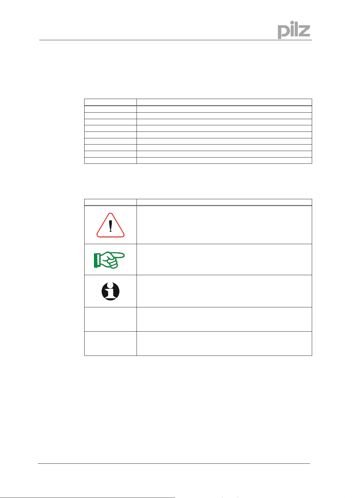
Screen layout:
The Motion Generator window presents the current map shape as a series of segments. In the
above picture position, velocity, acceleration and jerk are being viewed. The currently selected
segment is highlighted in red and the position of the mouse pointer is given in map coordinates
in the status bar.
When PMotion is first started a map consisting of a single segment is displayed. This map can
then be edited as required, or a previous session can be loaded from the PC disk.
The following sections detail all the menus, dialogue boxes and actions associated with the
Motion Generator.
Page 12 User Manual for PMotion
Page 13

7 PC based Motion Generator PMotion
7.2 Menus
7.2.1 Menu "File"
New Creates a new map with the default segment type "Polynomial".
Open Loads a map from the PC disk.
Close Closes the current map file. If the file has been changed, the user will
be indicated to save the changes.
Save Saves the current map to the PC disk.
Save as Saves the current map on using a different file name.
Print Prints the current map. In a dialogue box you can choose the printer.
Print Preview Preview a print – see what your program will look like when printed.
Printer Setup Printer configuration.
Send Send the current map via email.
Exit Quits PMotion.
7.2.2 Menu "Edit"
Undo You can undo the last change of your map you are working on.
Segment left Selects the segment on the left side of the currently selected segment.
Segment right Selects the segment on the right side of the currently selected
segment.
Insert Segment Inserts a segment to the left of the currently selected segment. The
new segment will be 1000 counts long and of a polynomial type. The
master cycle length will be stretched automatically.
Split Segment Splits a Segment into two parts.
Append Segment Adds a segment to the end of your map shape. The new segment will
be 1000 counts long and of a polynomial type. The master cycle length
will be stretched automatically.
Delete Segment Deletes the currently selected segment. You cannot delete the
segment if it is the only one in a map shape.
Segment parameters Opens a dialogue bar on the left side of the view, where you can
configure the currently selected segment settings.
User Manual
for PMotion
Page 13
Page 14
7 PC based Motion Generator PMotion
Map Settings Opens a dialogue box, where you can configure the map shape
settings.
Map variables Shows a dialogue box in which you can edit the map variables.
Colours and Lines Adjustment of colours and lines for the motion view.
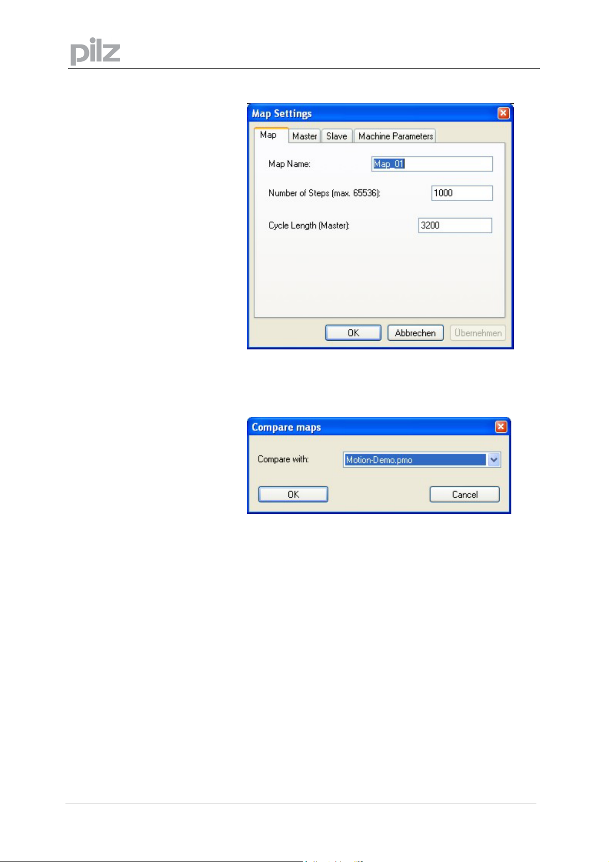
Show comparison map Show/Hide a further map in the motion view. Select a map in the
following dialog to compare it to the current map.
7.2.3 Menu "View"
Position Shows or hides the view „Position“.
Velocity Shows or hides the view „Velocity“.
Acceleration Shows or hides the view „Acceleration“.
Jerk Shows or hides the view „Jerk“.
Toolbar Shows or hides the toolbar.
Status bar Shows or hides the status bar.
Page 14 User Manual for PMotion
Page 15
7 PC based Motion Generator PMotion
7.2.4 Menu "Create"
Create Map Table Creates the current map shape as a map table in a ptf-file (ptf = PMC
text file). With the text editor PEdit you can download this map to the
controller.
Create Map Sequence Creates the current map shape as a map sequence in a ptf-file (ptf =
PMC text file). With the text editor PEdit you can download this
sequence to the controller. The internal Motion Generator on the
controller is able to generate maps from this sequence during runtime.
Download map table Downloads the current map shape as a map table directly to the
controller.
Download map sequence
Downloads the current map shape as a controller sequence directly to
the controller. The internal Motion Generator on the system is able to
generate maps from this sequence during runtime.
Import map
Active map from system
Imports the last map sequence to be executed (XS command) from
the connected controller.
Map sequence from system
Imports a map from a map sequence saved on a controller.
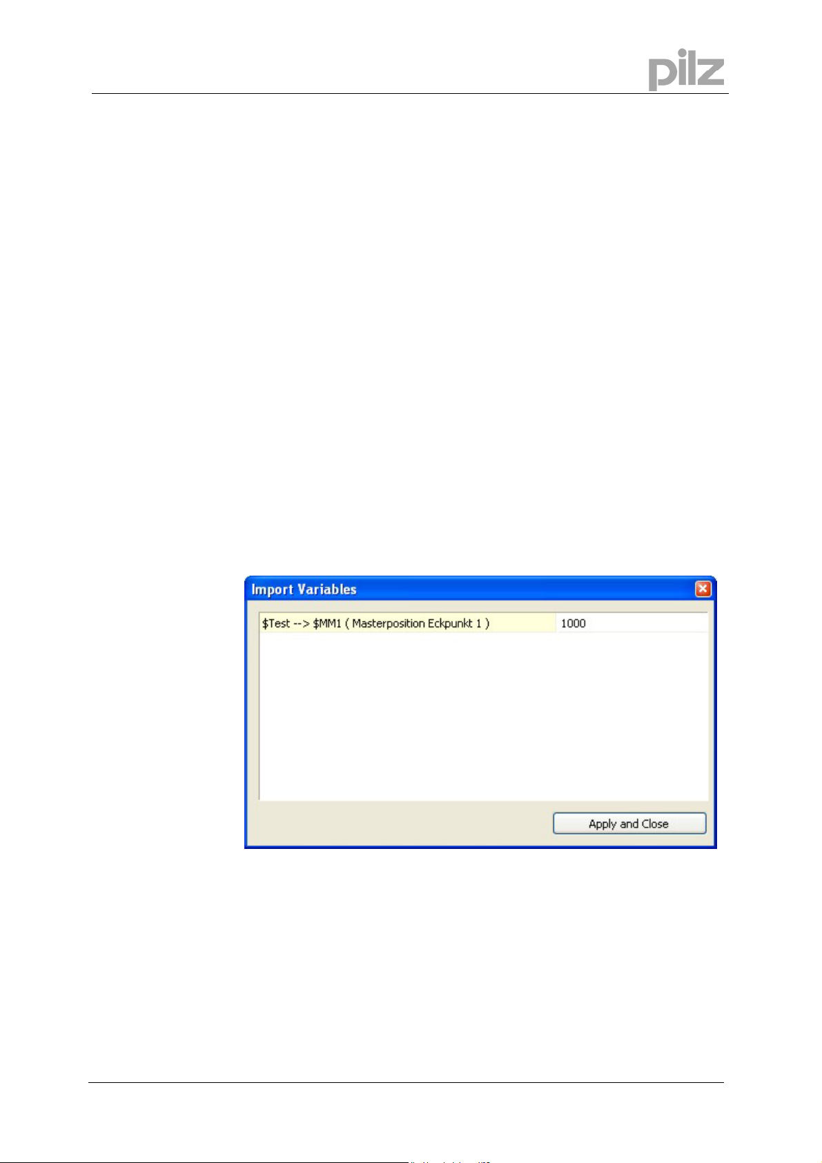
Map sequence from file
Imports a map from a map sequence saved in a ptf file.
If values in the map sequence are defined as variables, you can
enter a value for these during import for showing the map.
User Manual
Export map as FB for SoftPLC
for PMotion
Exports the current map (map table or map sequence) as a function
block for the system integrated Software PLC.
Page 15
Page 16

7.2.5 Menu "Programs"
PTerm Starts the terminal program PTerm.
PDrive Starts the setup software PDrive.
PScope Starts the scope function PScope.
PEdit Starts the text editor PEdit.
7.2.6 Menu "Window"
New window Opens a further window for the current document.
Cascade Arranges all the windows you are editing in a neat, cascaded, pile.
Tile Tiles all the windows you are editing horizontally across the screen.
Arrange icons Arranges all icons in the bottom area of the window.
7 PC based Motion Generator PMotion
Page 16 User Manual for PMotion
Page 17
7 PC based Motion Generator PMotion
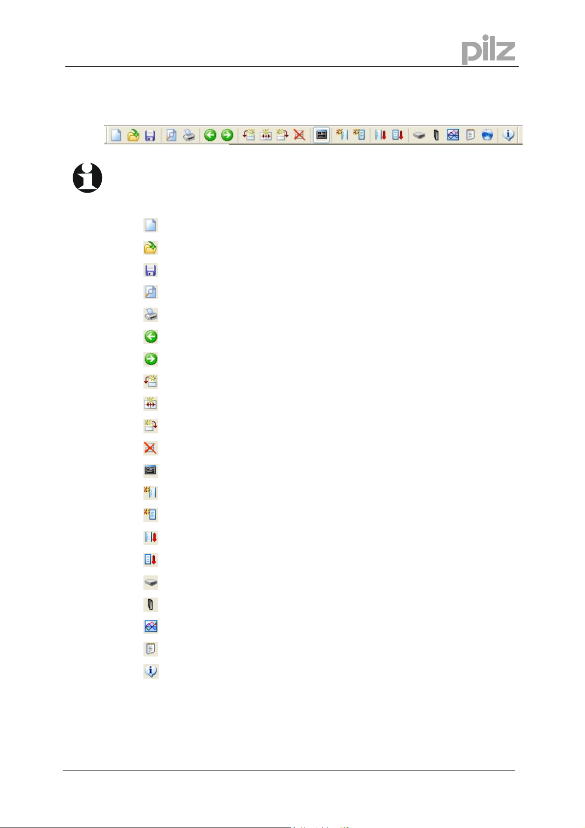
7.3 Toolbar
With the toolbar you have direct access to important functions of the program.
Creates a new map.
Opens an existing map.
Saves the current map file.
Displays full pages of the current map before printing.
Prints the current map.
Selects the segment on the left side of the currently selected segment.
Selects the segment on the right side of the currently selected segment.
Inserts a new segment to the left side of the currently selected segment.
Splits a segment into two parts.
Adds a segment to the end of your map shape.
Deletes the currently selected segment.
Opens a dialogue bar on the left side of the view to configure the segment settings.
Creates a map table in a ptf-file (ptf = PMC text file).
Creates a map sequence in a ptf-file (ptf = PMC text file).
Downloads a map table to the controller.
Downloads a map sequence to the controller.
Starts the terminal program PTerm.
Starts the setup software PDrive.
User Manual
for PMotion
Starts the scope function PScope.
Starts the text editor PEdit.
Opens the “About” dialog.
Page 17
Page 18

7.4 Map Settings
The map settings dialogue is presented when the menu option "Edit" -> "Map Settings"
is chosen.
The dialogue consists of four property pages:
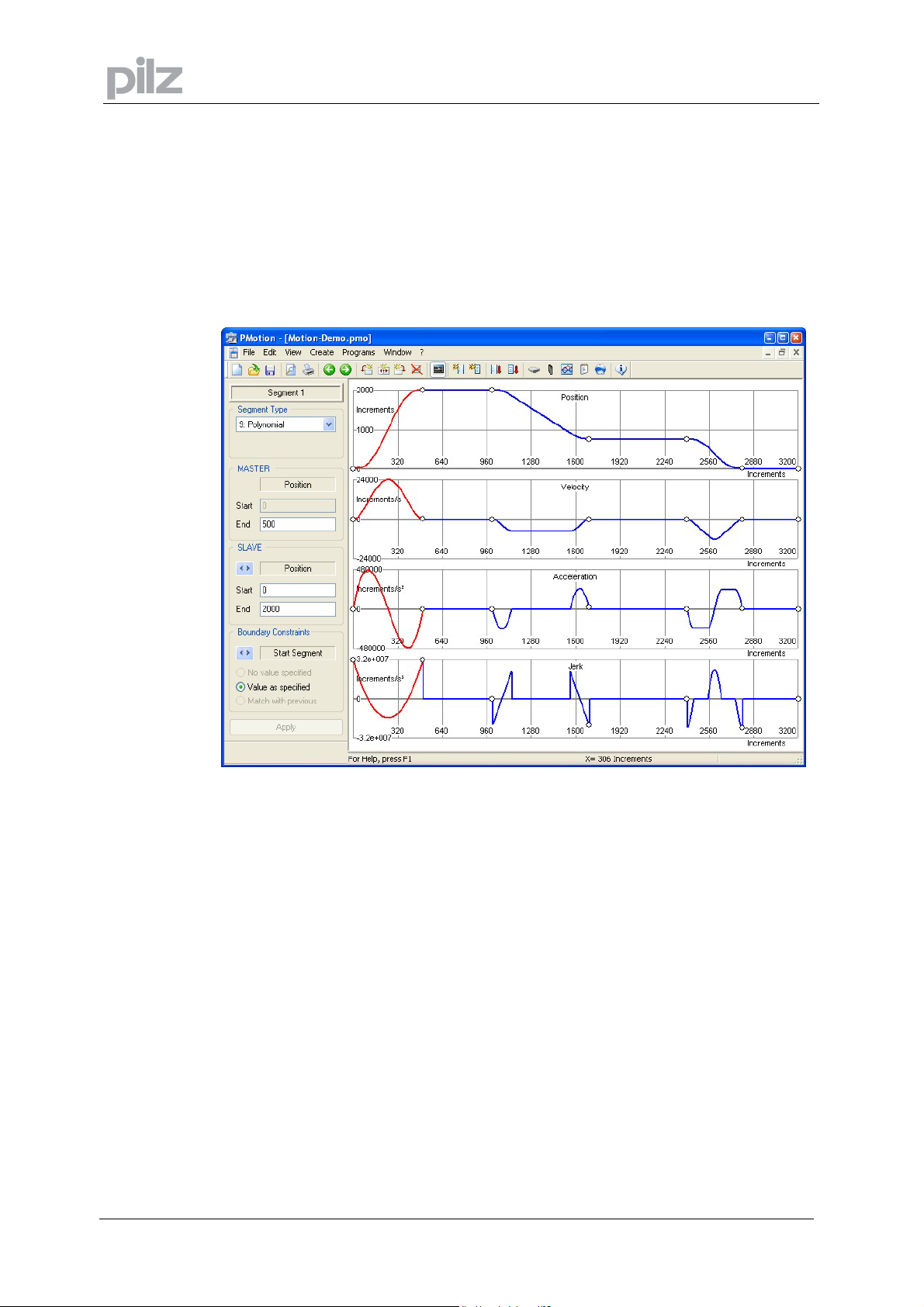
7.4.1 Property Page „Map“
7 PC based Motion Generator PMotion
Map Name:
Number of
Steps:
Cycle Length
(Master):
Each map has its unique name on the controller. The name consists of an alphanumeric
expression with a maximum of 20 characters. This identifier will be used for the map table
when it is downloaded into the controller.
When a map shape is turned into a map table the Motion Generator needs to know what
resolution you require. The more map steps the greater the resolution of the map table, but
also the larger the memory space for saving the table in the Flash EPROM. The maximum
number of steps is 65536.
The master length is the length of the map shape along the master axis (horizontal) in position
units. If this value is changed the whole map is scaled and all the master and slave positions
are affected. The length of the master axis and the machine’s cycle speed are used to calculate
the curves.
Page 18 User Manual for PMotion
Page 19

7 PC based Motion Generator PMotion
7.4.2 Property Page “Master”
Scaling / Unit
Offset
PMotion can work with user defined units. Therefore it needs the name of the chosen unit and
the scaling factor (numerator and denominator) for the conversion between the new unit and
the standard encoder counts. This factor is necessary, because the internal position values of
the controller must be defined in increments (encoder counts).
A offset of master position can be entered to shift the map horizontally.
Attention: The offset will not be transmitted to the motion control system. Use the command
“MB” to shift a map on the system.
User Manual
for PMotion
Page 19
Page 20

7.4.3 Property Page “Slave”
7 PC based Motion Generator PMotion
Scaling / Unit
Show
maximum
values
Like the master axis user defined units are also possible on the slave axis. Therefore PMotion
needs the name of the chosen unit and the scaling factor (numerator and denominator) for the
conversion between the new unit and the standard encoder counts. This factor is necessary,
because the internal position values of the controller must be defined in increments (encoder
counts).
The maximum values for position, velocity, acceleration and jerk can be defined. These
maximum values will be displayed as horizontal lines in the diagrams. The colour can be
changed in the dialog box “Colours and lines”.
Page 20 User Manual for PMotion
Page 21

7 PC based Motion Generator PMotion
7.4.4 Property Page "Machine Parameters"
Cycles/Minute
A map shape does not contain any time information. For a correct calculation of the derivations
and considering the mechanical limits of the machine you can set the machine cycles per
minute in this property page. This determines the constant velocity of the master axis and
allows PMotion to put a scale to the slave velocity, acceleration and jerk.
User Manual
for PMotion
Page 21
Page 22

7.5 Edit Segment parameters
The parameters of a segment are shown in the toolbar
on the left side of the PMotion window. This toolbar can
be toggled by using the button „Segment parameters“ in
the menu „Edit“.
The parameter bar is used to set all the parameters for
the selected segment. If you change segment selection
the parameter bar is updated automatically.
The toolbar remains on the screen while editing the map
or using other menu commands. This feature allows you
to perform quickly changes of the map shape and
analyse certain points.
Parameter changes can be applied by pressing the
“Return” button or the “Apply” button on the bottom of
the parameter bar. With this update method it is possible
to analyse the current segment and make quickly
changes.
7 PC based Motion Generator PMotion
Segment ...
Segment Type
Start / End
Master position
The available setting options are divided into various
subsections by borders and title descriptions.
Number of the current selected segment in the motion view.
In the „Segment type“ box you can select the mathematical function for the segment. It is
possible to choose from up to 16 different mathematical functions, which are described in
chapter 9 („Segment types).
There are extra settings for some segment types when pressing the button „Type parameters“.
These parameters depend on the selected segment type and can define the mathematical
function in more detail.
The default segment type is polynomial, which has no extra parameter settings.
The length of a segment is specified by the absolute start and end master position values.
The master start position corresponds to the end position of the previous segment. If you
change the start position of a segment, the end position of the previous segment will be
updated automatically.
Equally changing the master end position of a segment will influence the start position of the
next segment.
Attention: If the next segment is not able to accommodate the position change, a message box
appears indicating that the values have to be entered again.
Page 22 User Manual for PMotion
Page 23

7 PC based Motion Generator PMotion
Start / End
Slave
Passage
conditions
Apply
Depending on the current selected derivative of mathematical function the slave display refer to
position, velocity, acceleration or jerk. You can change from one derivative to another by
pressing the horizontal arrow buttons. If the text entry boxes are activated it is possible to
specify new slave values. This is especially the case if the passage condition „value as
specified“ is selected.
Altering slave positions modifies the current segment and the next segment.
Attention: If the next segment is not able to accommodate the changes, a message box
appears indicating that the values have to be entered again.
The available passage conditions at the start and the end of a segment depend on the selected
segment type. You can toggle between “Start Segment” and “End Segment” by pressing the
horizontal arrow buttons. The following passage conditions can be selected:
No value specified:
The value is fixed by the selected segment type.
Value as specified:
The value can be altered in a text entry box.
Match with previous:
The start value of the current selected segment corresponds to the end value of the previous
segment.
The changes are applied. The map shape is updated.
User Manual
for PMotion
Page 23
Page 24

7.6 Create a map
The number of steps is an important factor for creating a map. This parameter sets the
resolution of a map table (maximum 65536 steps). The higher the resolution of the table, the
smoother the motion will be, the more memory space is allocated in the flash EPROM of the
system. The number of map steps can be altered in the dialog box “Map Settings”. Furthermore
there are some relevant parameters for the creation of a map like master cycle length and
complexity of the calculated map.
There are two possibilities to create a map, to generate a map table or a map sequence
(sequence for internal calculation of a map).
7.6.1 Map Table
A map table can be created by pressing the button „Create map table“ in the menu „Create”.
This function generates an ASCII table of position values and saves it into a text file (extension
ptf = PMC text file). This file can be opened in the text editor PEdit and transmitted to the
controller.
7 PC based Motion Generator PMotion
7.6.2 Map Sequence
A map sequence can be created by pressing the button „Create map sequence“ in the menu
„Create”. This function generates a sequence with special variables, which represent all
relevant map parameters and saves it into a file. The controller can generate map tables at
runtime by executing this sequences. The generated ASCII file can be opened in the text editor
PEdit and transmitted to the controller.
Page 24 User Manual for PMotion
Page 25

7 PC based Motion Generator PMotion
7.7 Example of using the PC based Motion Generator PMotion
In the following example representing a printing machine a web is drawn through the machine
by using tension control. It is required to print on the web in dependence of existing print marks.
The circumference of the printing drum is not the same as the distance between the marks. The
speed of the drum has to match with the speed of the web while printing and to accelerate or
decelerate for the rest of the cycle for compensating the deviation between the drum
circumference and the print mark distance. The position data of the web is measured by an
encoder and of the drum by the encoder emulation of the motor amplifier.
A typical map for the print drum (Y-axis is slave) dependent on the web (X-axis is master) is:
User Manual
for PMotion
Page 25
Page 26

7 PC based Motion Generator PMotion
Segment 1 and 3 are constant velocity segments to reach an exact printing result, segment 2 is
a sine-squared velocity segment for catching up or pausing. The master cycle length is 23874
increments (300 mm with a resolution of 79.58 inc. per mm). The print area is 80 mm either side
of zero from position 17508 to 6336. The circumference of the print drum is 374 mm and the
encoder resolution is 27.76 inc. per mm. This indicates that the cycle length of the slave axis is
10382 inc. and the printing area of slave axis is from position 8155 through zero to 2210 inc.
How to create the map:
• Start the motion design tool PMotion. A default map with a polynomial segment appears in
the motion screen.
• Insert two segments by using the function „Append Segment“ in the menu „Edit“. The new
segments are polynomials, the default length is 1000 inc. The master cycle length is
matched automatically when inserting new segments.
• Open the dialog box “Map Settings“ in the menu „Edit“ or press „CTRL+M“. Type in a name
for the map in the text box „Map Name” or retain the default name. The default value of
number of steps (1000) can be kept on. Enter the master cycle length of 23874 increments.
When applying the new value a message box appears with the question, if the map should
be extended or the last segment has to be adapted. Please choose “Yes” for extending the
map.
• In the toolbar „Segment parameters“ on the left side of the window the segments can be
configured. Choose the segment types and edit the required master and slave values. To
change selection of segments click with the left mouse button into the area of a segment or
use the arrow buttons in the toolbar for segment navigation.
The velocity of slave axis in the area “Constant velocity” is calculated from the master
velocity (0.349 * V
). The result is 8328 increments per second.
master
Segment 1:
- Select segment type „Constant velocity“
- Enter master end position: 6336 inc.
- Select „Slave velocity“ by switching the right arrow button in the dialog „Slave“, select
„Value as specified“ for „Start segment“ in the dialog „Passage Conditions“ and enter
the slave velocity of 8328 inc./sec. in the text entry box „Slave start“. To apply the
changes press enter or the button “Apply” on the bottom of the segment parameters
toolbar.
Segment2:
- Select segment type „Sine-squared velocity“
- Enter master end position: 17508 inc. (start printing)
- Enter slave end position: 8155 inc. (start printing)
Segment3:
- Select segment type „ Constant velocity “
- Enter master end position: 23874 inc. (= master cycle length)
- Select „Slave velocity“ by switching the right arrow button in the dialog „Slave“, select
„Value as specified“ for „Start segment“ in the dialog „Passage Conditions“ and enter
the slave velocity of 8328 inc./sec. in the text entry box „Slave start“. To apply the
changes press enter or the button “Apply“ on the bottom of the segment parameters
toolbar.
Page 26 User Manual for PMotion
Page 27

7 PC based Motion Generator PMotion
• Save the map into a pmo-file.
• Create the map by using the functions „Create map table“ or „Create map sequence“ in the
menu „Create“. Open the generated file with the text editor PEdit and download it to the
controller.
For testing, execute the map on the system using two axes in virtual mode. For analysing
the movement, the scope function PScope can be used.
Example to start the map:
CH0.2;VM1;SB23874;SV20000;SA300000;DC300000;PC;VC+ (master axis)
CH0.1;VM1;SB10376;ML0.2;MW01000001;TMMap_01;XMMap_01 (slave axis)
The scope function can be used to show channel 1 demand position, channel 2 demand
position and channel 1 demand speed.
• If the map was created as a sequence, it can be calculated on the controller at runtime by
executing the map sequence as followed: CH0.1;XS map_01.
User Manual
for PMotion
Page 27
Page 28

8 Internal Motion Generator
The controller internal motion generator is a calculation engine for map tables. The map is
defined using specific variables (see chapter 10.4.2). The internal motion generator reads these
variables and calculates the corresponding map.
For initially creation of a map the PC based motion generator PMotion should be used. For
generating a map by the internal motion generator, a map sequence has to be created and
downloaded to the controller. If the sequence is present in the system, the calculation routine of
the internal motion generator has to be started. This is done using the command $MSTART=1
(often the last line in the map sequence). A message will be displayed in the terminal program
indicating that calculation process has been started. Success or failure of map creation is
indicated by further messages. If calculation has been finished successful, the new map table
will exist on the system.
An important feature of the internal motion generator is the possibility to modify the map
immediately by editing the specific variables from external systems, e. g. operators panel or
PLC. Thereby a change between master and slave positions can be realized very quickly, e. g.
to modify product lengths.
8.1 Commands for Internal Motion Generator
8 Internal Motion Generator
The following commands are significant for calculating a map in the internal motion generator:
• $MSTART is a trigger variable to start the generation of a map.
• $MRESET is a trigger variable to set all variables to their default values.
• $MNAME contains the name of the appropriate map table.
• $MREADY is a trigger variable used to indicate the end of map generation. During the map
calculation the variable is set to 0, when the map calculation is finished it is set to 1.
• $MNPT is used to define the number of map steps.
• $MSAVE is used to save the map on the controller ($MSAVE=1) after generating or not
($MSAVE=0).
Page 28 User Manual for PMotion
Page 29

8 Internal Motion Generator
8.2 Messages displayed in terminal and in status variable $MSTATUS
The internal motion generator reports progress and errors (or warnings) of map generation by
displaying messages in the terminal program. Furthermore coded message numbers are saved
in the status variable $MSTATUS.
The following error messages can occur during generation of a map:
Error
No.
0 Map generation successful.
1 Error, too less values defined.
2 Slave position information missing.
3 Segment type information missing.
4 Map name missing.
5 Map is currently active.
6 Master start value must be zero..
7 Master values are not strictly monotonic increasing.
8 Segment type index not found.
9 Variable $MWn not defined.
10
Start velocity (segment type 1) not defined.
11 Slave position at segment start must be matched.
12 Percentage for start value of a segment missing (Seg. type 2 or 3).
13 Percentage for end value of a segment missing (Seg. type 2 or 3).
14 Percentage for start value must be less than for end value (Seg. type 2 or 3).
15 Percentage for start value must be less than 50% (Seg. type 3).
16 Percentage for end value must be greater than 50% (Seg. type 3).
17 Start velocity (Seg. type 3) not defined.
18 Start acceleration (Seg. type 4) not defined.
19 Start jerk (Seg. type 4) not defined.
20 End velocity (Seg. type 4) not defined.
21 End acceleration (Seg. type 4) not defined.
22 End jerk (Seg. type 4) not defined.
23 Sine % (Seg. type 5) must be defined by $MA.
24 Constant % (Seg. type 5) must be defined by $MB.
25 Cosine % (Seg. type 5) must be defined by $MC.
26 Sum of Sine %, Constant % and Cosine % (Seg. type 5) must be 100 %.
27 $MNPT not defined.
Error messages
User Manual
for PMotion
Page 29
Page 30

8.3 Example of using the internal Motion Generator
This example refers to the example already described in section 7.7 on page 25. The internal
controller calculation of the tabular values is designed so that entries made via an operator
panel will influence the map. In this example, the print length and the distance between the print
marks are modified. It is assumed that the print length will be entered via the operator panel in
the variable $LEN in mm, and that the distance between the print markers will be entered in
variable $REG, also in mm. The dimensions stated in mm must be converted into increments.
In variables $ECM and $PCM, the conversion factors are increments/mm x 100. The
corresponding messages are output to the operator panel with the variables $MSG. The
command line for starting the motion generator is normally part of a program which is stored in
the controller’s Flash-EPROM. This program is called up when the map is to be recalculated.
The variables $REG and $LEN are written via the operator panel!
$REG=300 # Registration distance, mm
$LEN=150 # Print length, mm
$ECM=7958 # Web Encoder Counts x 100
$PCM=2776 # Print Drum Encoder Counts x 100
# Sequence for map calculation:
ES Map_01
$MSG=3 # Operators Panel Message „Calculating Map“
$MRESET=1 # Reset map variables
$MNAME=Map_01 # Map name
# Master
$MM0=0 # Master start position
$MM1=((($LEN/2+5)*$ECM)/100) # Half print distance (+5mm window)
$MM3=($REG*($ECM/100)) # Registration distance
$MM2=($MM3-$MM1) # Start of print
# Slave
$MS0=0 # Slave start position
$MS1=((($LEN/2+5)*$PCM)/100) # Half print distance (+5mm window)
$MS3=(374*($PCM/100)) # Cycle length slave
$MS2=($MS3-$MS1) # Start of print
# Segment 1: Constant Velocity
$MF1=1 # Constant velocity for printing
$MA1=348831 # Start velocity
$MW1=21000000 # Velocity matched with previous segment
# Segment 2: Sine-squared velocity
$MF2=3 # Sine-squared velocity for catching up / pausing
$MX2=0 # Start at 0%
$MY2=100000000 # End at 100%
$MW2=22001000 # End position segment 2 defined
# Segment 3: Constant velocity
$MF3=1 # Constant velocity for printing
$MW3=22000000 # Velocity matched with previous segment
$MNPT=1000 # Number of steps (points)
$MSTART=1 # Trigger internal motion generator
NS
8 Internal Motion Generator
Page 30 User Manual for PMotion
Page 31

8 Internal Motion Generator
Downloading and testing map sequence:
• Download the map sequence to a controller by using the text editor PEdit and generate
the map by entering the command line “XS Map_01” into terminal program.
The variable $MSTART=1 at the end of the sequence starts the map calculation. The
messages „Mapgenerator started!“ while generating and “Mapgenerator ready!” when
finished map generation are displayed in the terminal program.
• The generated map can be tested by using two axes in virtual mode analysed by using
scope function PScope to record movements.
Example to start the map:
CH0.2;VM1;SB$MM3;SV20000;SA300000;DC300000;PC;VC+ (master axis)
CH0.1;VM1;SB$MS3;ML0.2;MW01000001;TMMap_01;PC;XMMap_01 (slave axis)
The scope function can be used to show channel 1 demand position, channel 2 demand
position and channel 1 demand speed.
User Manual
for PMotion
Page 31
Page 32

9 Segment Types
The following segment types are available in the motion generator (The index number refers to
the value that would be saved in the map variable $MFnn):
Index
0 Constant Position
1 Constant Velocity
2 Constant Acceleration
3 Sine-Squared Velocity
4 Cycloidal
5 Modified Trapezoidal
6 Modified Sine
7 Triple Harmonic
8 Sinusoidal
9 Polynomial
10 Ramp
11 Throw
12 <reserved>
13 Quadratic Spline
14 Cubic Spline
15 Sine-Constant-Cosine
16 Simple Harmonic
9 Segment Types
Segment Type
In the following sections all segment types are described in more detail. The description
contains guidelines for using the segments and what parameters can be modified. Furthermore
a list of specific variables depending on the different segment types is given out.
The units of parameters refer to the controller internal motion generator. The following
abbreviations are used in the description:
P: Position $: Variable
V: Velocity nn: Segment number: 01 to 100 is possible
A: Acceleration [...]: Parameters not alterable
J: Jerk
$MMnn und $MSnn must be entered in increments!
Page 32 User Manual for PMotion
Page 33

9 Segment Types
9.1 Segment Type "Constant Position"
This segment type is a polynomial segment with both the
velocity and the acceleration fixed to zero. The slave position
remains constant throughout at the end value of the previous
segment. This means that only the position is matched from the
previous segment, which can lead to an instantaneous change
in velocity.
Parameters:
• Segment type $MFnn=0
• Segment start constraints: [P matched, V, A & J not defined]
• Segment end constraints: [P, V, A & J not defined]
• $MWnn=20000000
• Master end position $MMnn=<value> sets end segment master position
Slave end position $MSnn=<value> will be identical in value to $MSnn-1
User Manual
for PMotion
Page 33
Page 34

9.2 Segment Type "Constant Velocity"
This segment type is a polynomial segment with the
acceleration fixed at zero. The velocity is constant throughout
and is determined either by the end velocity of the previous
segment or by a specific value. The slave position change
depends on both the velocity value for the segment and the
value of the master increment.
Parameters:
• Segment type $MFnn=1
• Segment start constraints: [P matched], V matched ($MWnn=22000000) or specified
($MWnn=21000000), [A & J not defined]
• Segment end constraints: [P, V, A & J not defined]
• Master end position $MMnn=<value> sets end segment master position
• Slave end position $MSnn=<value> will be correct for map as saved
• Start velocity $MAnn=<value> sets start velocity if $MWnn=21000000. Scaling of $MAnn is
as a polynomial segment.
9 Segment Types
Page 34 User Manual for PMotion
Page 35

9 Segment Types
9.3 Segment Type "Constant Acceleration"
In this segment type the acceleration is fixed at a constant value.
For the first half of the segment the acceleration is positive, for
the second half it is negative. The difference between start and
end positions determines the value of the acceleration and
deceleration.
Parameters:
• Segment type $MFnn=2
• Segment start constraints: [P matched], V matched ($MWnn=22000000) or not matched
($MWnn=20000000), [A & J not defined]
• Segment end constraints: [P specified, V, A & J not defined]
• Master end position $MMnn=<value> sets end segment master position
• Slave end position $MSnn=<value> sets end segment slave position
• Percentage of segment used: Start at $MXnn=<value> & end at $MYnn=<value> (see
chapter 10.1 page 49)
User Manual
for PMotion
Page 35
Page 36

9 Segment Types
9.4 Segment Type "Sine-Squared Velocity" and "Cycloidal"
Mathematically both the “Sine-Squared Velocity” segment type and
the “Cycloidal” segment type are identical. The acceleration profile
is one cycle of a sine wave, the length is set by the master position
increment and the magnitude is set by the slave position change
across the segment.
Parameters:
• Segment type $MFnn=3 for sine-squared velocity and $MFnn=4 for cycloidal
• Segment start constraints: [P matched], V matched ($MWnn=22000000) or not specified
($MWnn=20222222), [A & J not defined]
• Segment end constraints: [P specified, V, A & J not defined]
• Master end position $MMnn=<value> sets end segment master position
• Slave end position $MSnn=<value> sets end segment slave position
• Percentage of segment used: Start at $MXnn=<value> & end at $MYnn=<value> (see
chapter 10.1 page 49)
Page 36 User Manual for PMotion
Page 37

9 Segment Types
9.5 Segment Type "Modified Trapezoidal"
For this segment type the magnitude of the acceleration profile
is set by the master position increment and the slave position
change across the segment. This type of segment is useful for
heavy, stiff systems running at low or medium speeds.
Parameters:
• Segment type $MFnn=5
• Segment start constraints: [P matched], V matched ($MWnn=22000000) or not specified
($MWnn=20000000), [A & J not defined]
• Segment end constraints: [P specified, V, A & J not defined]
• Master end position $MMnn=<value> sets end segment master position
• Slave end position $MSnn=<value> sets end segment slave position
• Percentage of segment used: Start at $MXnn=<value> & End at $MYnn=<value> (see
chapter 10.1 page 49)
User Manual
for PMotion
Page 37
Page 38

9.6 Segment Type "Modified Sine"
For this segment type the magnitude is set by the master
position increment and the slave position change across the
segment. This type of segment is useful for systems with some
backlash and for medium or high speeds.
9 Segment Types
Parameters:
• Segment type $MFnn=6
• Segment start constraints: [P matched], V matched ($MWnn=22000000) or not specified
($MWnn=20000000), [A & J not defined]
• Segment end constraints: [P specified, V, A & J not defined]
• Master end position $MMnn=<value> sets end segment master position
• Slave end position $MSnn=<value> sets end segment slave position
• Percentage of segment used: Start at $MXnn=<value> & End at $MYnn=<value> (see
chapter 10.1 page 49)
Page 38 User Manual for PMotion
Page 39

9 Segment Types
9.7 Segment Type "Triple Harmonic"
This segment will always start and finish with zero velocity and
acceleration (the possibility to match velocity has been switched
off for this segment). The acceleration profile is defined by
following parameters: Three normalised amplitudes for the
harmonics used to construct the curve. These values form the
three coefficients of a three term fourier series. Example: set the
first harmonic to 2*Pi and both the second and third harmonics
to zero, then the acceleration profile will be identical to a
cycloidal segment. Usually only the first two harmonics have to
be specified and the third is calculated to satisfy the constraints
from the neighbouring segments.
Parameters:
• Segment type $MFnn=7
• Segment start constraints: [P matched], V matched ($MWnn=22000000) or not specified
($MWnn=20000000), [A & J not defined]
• Segment end constraints: [P specified, V, A & J not defined]
• Master end position $MMnn=<value> sets end segment master position
• Slave end position $MSnn=<value> sets end segment slave position
• Amplitudes for the three harmonics are $MAnn<value>, $MBnn<value> and
$MCnn<value> in normalised units of a three term fourier series x 10
6
.
User Manual
for PMotion
Page 39
Page 40

9.8 Segment Type "Sinusoidal"
This segment type is a sine wave in master – slave position. Start position (in terms of
degrees), Amplitude (in slave axis units) and the number of sine wave cycles used for the
segment can be set.
These three parameters determine the slave end position and the velocity and acceleration
within the segment. Due to the default setting “velocity matched with previous segment“ the
curve often looks like a „S“ instead of a sine wave. This is because a sine wave doesn’t start
with zero velocity and the end velocity of other segments is zero.
Parameters:
• Segment type $MFnn=8
• Segment start constraints: [P matched], V matched ($MWnn=22000000) or not specified
($MWnn=20000000), [A & J not defined]
• Segment end constraints: [P specified, V, A & J not defined]
• Master end position $MMnn=<value> sets end segment master position
• Slave end position $MSnn=<value> sets end segment slave position, value will be ignored
by the motion generator, because end position is determined by other parameters.
• Amplitude of sine wave $MAnn<value> in encoder counts (inc.).
• Cycle start angle $MBnn<value> in degrees x 10
• Number of sine wave cycles $MCnn<value> (no units x 10
9 Segment Types
6
.
6
).
Page 40 User Manual for PMotion
Page 41

9 Segment Types
9.9 Segment Type "Polynomial"
This segment type can be used multilaterally and is the most adjustable segment. Therefore it
is the default segment type. A polynomial segment is a shape which fits various boundary
constraints.
Parameters:
• Segment type $MFnn=9
• Segment start and end constraints: The segment type „Polynomial“ determines its shape
by applying boundary constraints. The variable $MWnn is used for setting these constraints
and has the following format:
A eight digit decimal number contains the constraints for each of the four derivatives at
both ends of the segment. Each digit represents a boundary constraint and can have one
of the following three values:
0 No value specified: The boundary constraint will not be applied.
1 Value as specified: This boundary constraint will be specified by the relevant variable
(see below).
2 Matched with previous: This boundary constraint can only be used at segment start.
The start value of the segment matches equivalent with the end boundary value of the
previous segment.
$MWnn
Entry
Digit 8
Digit 7
Digit 6
Digit 5
Digit 4
Digit 3
Digit 2
Digit 1
Therefore the default setting for the variable $MWnn of a polynomial segment is 22201110.
Example: $MWnn=21101110 indicates that the start velocity and the start acceleration
along with the end velocity and acceleration have been specified. The variables $MAnn,
$MBnn, $MXnn and $MYnn contain the relevant values and need to be present for this
segment.
Segment
boundary
Start
End
Boundary Constraint Default value
Position
Velocity
Acceleration
Jerk
Position
Velocity
Acceleration
Jerk
2 (matched with previous) cannot
be changed
2 (matched with previous)
2 (matched with previous)
0 (no value specified)
1 (value as specified) cannot be
changed
1 (value as specified)
1 (value as specified)
0 (no value specified)
User Manual
The format of this constraint word applies to all segment types, though different
segments have different limitations for the boundary constraints.
for PMotion
Page 41
Page 42

9 Segment Types
• Master end position $MMnn=<value> sets end segment master position
• Slave end position $MSnn=<value> sets end segment slave position
• Derivative specification parameters are used when the segment constraint specifies that
the particular derivative is specified:
Segment
Boundary
Start
End
Derivative Variable Units:
Slave encoder counts (inc.) per
Velocity
Acceleration
Jerk
Velocity
Acceleration
Jerk
$MAnn
$MBnn
$MCnn
$MXnn
$MYnn
$MZnn
6
Master counts
1x10
8
Master counts
1x10
1x10⁹ Master counts3
1x10⁶ Master counts
8
Master counts
1x10
1x10⁹ Master counts3
2
2
Examples: For every master position count:
$MAnn=1000000 means that slave position increases by 1 count.
$MAnn=-24000000 means that slave position decreases by 24 counts.
$MAnn=50000 means that slave position increases by 0.05 counts.
$MBnn=50000000 means that slave velocity increases by 0.5 counts per master count
(equivalent to a increase in $MAnn of 500000).
$MZnn=-2000000000 means that slave acceleration decreases by 2 counts per master count
(equivalent to a decrease in $MYnn of 200000000).
Page 42 User Manual for PMotion
Page 43

9 Segment Types
9.10 Segment Type "Ramp"
The profile of a ramp segment is shown in the diagram. The
width of the acceleration and deceleration pulses can be set
(here acceleration set to 20% and deceleration set to 40%).
Parameters:
• Segment type $MFnn=10
• Segment start constraints: [P matched], V matched ($MWnn=22000000) or not specified
($MWnn=20000000), [A & J not defined]
• Segment end constraints: [P specified, V, A & J not defined]
• Master end position $MMnn=<value> sets end segment master position
• Slave end position $MSnn=<value> sets end segment slave position
• Length of acceleration pulse at segment start $MAnn<value> and of deceleration pulse at
segment end $MBnn<value> in percent x 10
100%).
6
(range 0 to 100%; $MAnn+$MBnn <=
User Manual
for PMotion
Page 43
Page 44

9.11 Segment Type "Throw"
The segment type “Throw” starts with a smooth motion profile
and ends with both velocity and acceleration at zero, with a
slave position change of zero. The magnitude of the position
change at the midpoint of the segment is changeable. The
segment is symmetrical about the midpoint and should only be
used in preference to two sequential ramp segments.
Parameters:
• Segment type $MFnn=11
• Segment start constraints: [P matched], V matched ($MWnn=22000000) or not specified
($MWnn=20000000), [A & J not defined]
• Segment end constraints: [P, V, A & J not defined]
• Master end position $MMnn=<value> sets end segment master position
• Slave end position $MSnn=<value> sets end segment slave position, value will be ignored
by the motion generator (value is identical with $MSnn-1).
• Extent of throw $MAnn<value> in slave position units.
9 Segment Types
Page 44 User Manual for PMotion
Page 45

9 Segment Types
9.12 Segment Type "Quadratic Spline"
A quadratic spline is a special case of a polynomial segment.
The position and velocity are both continuously to the previous
segment. The length and width of the segment can be defined.
A number of these segments perform a quadratic spline
between the data points (end segment coordinates).
Parameters:
• Segment type $MFnn=12
• Segment start constraints: [P und V matched, A & J not defined]
• Segment end constraints: [P specified, V, A & J not defined]
• Master end position $MMnn=<value> sets end segment master position
• Slave end position $MSnn=<value> sets end segment slave position
User Manual
for PMotion
Page 45
Page 46

9.13 Segment Type "Cubic Spline"
A cubic spline is a special case of a polynomial segment. The
position, velocity and acceleration are continuously to the
previous segment. The length and width of the segment can be
defined. A number of these segments perform a cubic spline
between the data points (end segment coordinates).
Parameters:
• Segment type $MFnn=13
• Segment start constraints: [P, V und A matched, J not defined]
• Segment end constraints: [P specified, V, A & J not defined]
• Master end position $MMnn=<value> sets end segment master position
• Slave end position $MSnn=<value> sets end segment slave position
9 Segment Types
Page 46 User Manual for PMotion
Page 47

9 Segment Types
9.14 Segment Type "Sine-Constant-Cosine"
The „Sine-Constant-Cosine“ type is a very adjustable segment
type and is often be used in place of other segment types with
sine and cosine acceleration profiles. The acceleration profile is
a sine wave followed by a constant area and a cosine wave. It
is possible to modify the segment portions by changing the
relevant percentage values and so to create very complex
shapes. The magnitude of the acceleration is set by the master
increment and the slave position change.
Parameters:
• Segment type $MFnn=14
• Segment start constraints: [P matched], V matched ($MWnn=22000000) or not defined
($MWnn=20000000), [A & J not defined]
• Segment end constraints: [P specified, V, A & J not defined]
• Master end position $MMnn=<value> sets end segment master position
• Slave end position $MSnn=<value> sets end segment slave position
6
• Length of sine acceleration at segment start $MAnn<value> in percent x 10
(range 0 to
100%).
• Length of constant acceleration in the middle of the segment $MBnn<value> in percent x
6
10
(range 0 to 100%).
6
• Length of cosine acceleration at segment end $MCnn<value> in percent x 10
(range 0 to
100%).
• Percentage of segment used: Start at $MXnn=<value> & End at $MYnn=<value> (see
chapter 10.1 page 49)
Note: $MAnn + $MBnn + $MCnn = 100%
User Manual
for PMotion
Page 47
Page 48

9 Segment Types
9.15
Segment Type "Simple Harmonic"
This segment type has an acceleration profile of the first half of
a cosine wave. The magnitude of the acceleration profile is set
by the master position increment and the slave position change.
It is possible to use only parts of the segment by entering start
and end percentage values. This segment type is useful for
systems with some backlash at low to medium speeds.
Parameters:
• Segment type $MFnn=15
• Segment start constraints: [P matched], V matched ($MWnn=22000000) or not defined
($MWnn=20000000), [A & J not defined]
• Segment end constraints: [P specified, V, A & J not defined]
• Master end position $MMnn=<value> sets end segment master position
• Slave end position $MSnn=<value> sets end segment slave position
• Percentage of segment used: Start at $MXnn=<value> & End at $MYnn=<value> (see
chapter 10.1 page 49).
Page 48 User Manual for PMotion
Page 49

10 Motion Generator: Features and Functions
10
10.1
Motion Generator: Features and Functions
This section contains detailed explanations of certain features of the motion generator and
some summaries of the information contained in the previous section (Segment types).
Start and End Percentages of a Segment
For the following segment types it is possible to define, which part of the segment is used:
2: Constant Acceleration
3: Sine-Squared Velocity
4: Cycloidal
5: Modified Trapezoidal
6: Modified Sine
10: Ramp
14: Sine-Constant-Cosine
15: Simple Harmonic
The entry of the percentage values is done by using the variables $MXnn und $MYnn for the
controller internal motion generator and in PMotion by pressing the button „Type parameters“ in
the segment parameters toolbar.
Scaling:
• PC based motion generator (PMotion):
Required percentage values, entered directly in the text entry boxes in the dialog „Type
parameters“.
• Controller internal motion generator:
Required percentage values x10
100%).
The following diagram illustrates the effect of setting both the start and end percentages to
values ≠ 0 for the segment type „Constant acceleration“.
$MXnn
Anfang [%]
$MYnn
Ende [%]
6
, into variables $MXnn and $MYnn ($MXnn+$MYnn ≤
User Manual
By changing the start and end percentage special segment profiles can be created, e. g. a
modified sine profile with no deceleration and with an acceleration ≠ 0 at the end of the
segment.
for PMotion
Page 49
Page 50

10.2 Summary of Segment Constraints
Segment Type Segment start constraints
10 Motion Generator: Features and Functions
0: Constant Position
1: Constant Velocity
2: Constant Acceleration
3: Sine-Squared Velocity
4: Cycloidal
5: Modified Trapezoidal
6: Modified Sine
7: Triple Harmonic
8: Sinusoidal
10: Ramp
11: Throw
14: Sine-Constant-Cosine
15: Simple Harmonic
9: Polynomial
12: Quadratic Spline
13: Cubic Spline
P
matched
V A J not specified
P
matched
V matched or specified,
A J
not specified
P matched
V matched or not specified
A J
not specified
P matched
V A J
matched or specified or not specified
P V matched
A J not specified
P V A matched
J not specified
Legend:
P: Position V: Velocity
A: Acceleration J: Jerk
• Matched means that the derivative value doesn’t change from the
end of one segment to the beginning of the next (matched with previous).
• Specified means that the derivative value can be set at that point
on the segment (value as specified).
• Not specified means that the derivative value cannot be altered at that point of the
segment (no value specified).
Page 50 User Manual for PMotion
Page 51

10 Motion Generator: Features and Functions
Segment Type Segment end constraints
0: Constant Position
1: Constant Velocity
8: Sinusoidal
11: Throw
2: Constant Acceleration
3: Sine-Squared Velocity
4: Cycloidal
5: Modified Trapezoidal
6: Modified Sine
7: Triple Harmonic
10: Ramp
13: Quadratic Spline
14: Cubic Spline
15: Sine-Constant-Cosine
16: Simple Harmonic
9: Polynomial
Legend:
P: Position V: Velocity
A: Acceleration J: Jerk
• Matched means that the derivative value doesn’t change from the end of one segment to
the beginning of the next (matched with previous).
P V A J not specified
P matched
V A J not specified
P matched
V A J specified or not specified
• Specified means that the derivative value can be set at that point on the segment (value
as specified).
• Not specified means that the derivative value cannot be altered at that point of the
segment (no value specified).
User Manual
for PMotion
Page 51
Page 52

10 Motion Generator: Features and Functions
10.3 Summary of Segment Types and their Parameters
The following table summaries the variables used for each segment type in the controller
internal motion generator:
Segment Type
$MMnn $MSnn $MFnn $MAnn $MBnn $MCnn $MXnn $MYnn $MZnn $MWnn
Constant Position
Constant Velocity
Constant
Acceleration
Sine-Squared
Velocity
Cycloidal
Modified
Trapezoidal
Modified Sine
Triple Harmonic
Sinusoidal
Polynomial
Ramp
Throw
>
>
> >
> >
> >
> >
> >
> >
>
r
> >
> >
> >
0
1 Start
2 Start % End %
3 Start % End %
4 Start % End %
5 Start % End %
6 Start % End %
7 1.
8 Amplitude Cycle
9 Start
10 Start % End %
11 Extent of
Velocity
Harmonic
Velocity
Throw
*
2.
Harmonic
Start
Start
Accel.
3.
Harmonic
No. of
Cycles
Start
Jerk
End
Velocity
End
Accel.
End
Jerk
>
>
>
>
>
>
>
>
>
>
>
Quadratic Spline
Cubic Spline
Sine-ConstantCosine
Simple Harmonic
> >
> >
> >
> >
13
14
15 Sin % Constant % Cosine % Start % End %
16 Start % End %
> Standard definition applies
r Variable may be present (and standard definition applies), but will not be used
<blank> The variable does not apply to the segment type
<text> Short description of the meaning of the variable specific to the segment type
* Start velocity will only be required for segment type „Constant Velocity“ if the
velocity is not matched with previous segment.
>
>
Page 52 User Manual for PMotion
Page 53

10 Motion Generator: Features and Functions
10.4
Technical Information about the Motion Generator
This section details some technical information about the motion generator.
10.4.1 Maximum number of segments
The maximum number of segments of a map is limited by memory to 100 in both the PC based
motion generator PMotion and the controller internal motion generator.
10.4.2 Variable names used by the internal Motion Generator
Map start coordinates:
• $MM0: Master position (range ±4000000 inc.)
• $MS0: Slave position (range ±4000000 inc.)
For each segment (nn is 1 to 100 inclusive, leading zero when appropriate):
• $MFnn: Segment type (range 0 to15 inclusive, no units)
• $MMnn: Master position (range ±4000000 inc.).
• $MSnn: Slave position (range ±4000000 inc.).
• $MWnn: constraint word:
$MWnn – Entry Segment boundary
Boundary constraint
Digit 8
Digit 7
Digit 6
Digit 5
Digit 4
Digit 3
Digit 2
Digit 1
Each digit can be 0 (no value specified), 1 (value as specified) or 2 (matched with previous).
Valid entries will depend on the segment type.
• $MMSB: contains the master cycle length after calculation.
• $MSSB: contains the slave cycle length after calculation.
Start
End
Position
Velocity
Acceleration
Jerk
Position
Velocity
Acceleration
Jerk
User Manual
for PMotion
Page 53
Page 54

10 Motion Generator: Features and Functions
• $MAnn, $MBnn, $MCnn, $MXnn, $MYnn & $MZnn: The meaning of the variables is
dependent on the segment type, as shown in the following table:
Segment
Variables
Description
Type
1 $MAnn Start velocity, required only when „Value as
specified“ is selected using $MWnn.
2 $MXnn & $MYnn Start & End percentages x 106
3 $MXnn & $MYnn Start & End percentages x 106
4 $MXnn & $MYnn Start & End percentages x 106
5 $MXnn & $MYnn Start & End percentages x 106
6 $MXnn & $MYnn Start & End percentages x 106
7 $MAnn, $MBnn & $MCnn Normalised amplitudes of the three harmonics of
a three term fourier series x 10
8 $MAnn, $MBnn & $MCnn Amplitude (inc.), Cycle start angle (degrees x 106)
and No. of cycles (no units x 10
9 $MAnn, $MBnn
$MCnn, $MXnn
Start & End derative values
(when applicable with $MWnn).
6
6
)
$MYnn & $MZnn
10 $MAnn & $MBnn Start & End percentages x 106
11 $MAnn Extent of throw (inc.)
13 $MAnn Slave end position (inc.)
15 $MAnn, $MBnn,
$MCnn,
$MXnn & $MYnn
Percentage x 106 of sine-, constant- or cosine
portion of the segment.
Start & End percentages x 10
6
16 $MXnn & $MYnn Start & End percentages x 106
• $MNAME specifies the name of the map.
• $MNPT specifies the number of points saved in the map table (max. 65536).
• $MSTART is a trigger variable to start calculation of a map. This variable is usually set to 1
at the end of a map sequence to start calculation.
• $MREADY is a trigger variable to indicate the status of map calculation. The variable is set
to 0 while calculating and to 1 when calculation is finished.
• $MSTATUS is a status variable used to return success or failure of map generation: Zero
indicates success, a non-zero value indicates failure (See chapter 8.2 Page 29).
• $MRESET is a trigger variable to set all variables to their default values.
• $MSAVE is used to save the map on the controller ($MSAVE=1) after generating or not
($MSAVE=0).
Page 54 User Manual for PMotion
Page 55

11 Index
11 Index
$
$MA ................................................................................. 54
$MB ................................................................................. 54
$MC ................................................................................. 54
$MF ................................................................................. 53
$MM ................................................................................. 53
$MMSB ............................................................................ 53
$MNAME ................................................................... 28, 54
$MNPT ...................................................................... 28, 54
$MREADY ................................................................. 28, 54
$MRESET .................................................................. 28, 54
$MS ................................................................................. 53
$MSAVE .................................................................... 28, 54
$MSSB ............................................................................ 53
$MSTART ........................................................................ 54
$MSTATUS ............................................................... 29, 54
$MW ................................................................................ 53
$MX ................................................................................. 54
$MY ................................................................................. 54
$MZ ................................................................................. 54
A
About this manual .............................................................. 7
C
Create a map ................................................................... 24
Map-Sequence ........................................................... 24
Map-Table .................................................................. 24
D
Designations ...................................................................... 9
E
Error messages ............................................................... 29
Example of using the internal Motion Generator ............. 30
Example of using the PC based Motion Generator ......... 25
F
Features and Functions ................................................... 49
G
General Description ........................................................... 9
Introduction ......................................................................12
M
Map-Sequence ...................................................................9
Map-Settings ....................................................................18
Map-Shape .........................................................................9
Map-Table ..........................................................................9
Maximum number of segments ........................................53
Messages displayed in the terminal .................................29
Motion Generator Overview .............................................10
P
PMotion
Introduction .................................................................12
Menus .........................................................................13
Create ....................................................................15
Edit ........................................................................13
File .........................................................................13
Programs ...............................................................16
View .......................................................................14
Window ..................................................................16
Toolbar ........................................................................17
S
Segment .............................................................................9
Segment Types
Constant Acceleration .................................................35
Constant Velocity ........................................................34
Cubic Spline ................................................................46
Modified Sine ..............................................................38
Modified Trapezoidal ..................................................37
Polynomial ..................................................................41
Quadratic Spline .........................................................45
Simple Harmonic ........................................................48
Sine-Constant-Cosine .................................................47
Sine-Squared Velocity ................................................36
Sinusoidal ...................................................................40
Throw ..........................................................................44
Triple Harmonic ..........................................................39
Segment Types ................................................................32
Constant Position ........................................................33
Segment-parameters .......................................................22
Segmenttypen
Cycloidal .....................................................................36
Start and End Percentages of a Segment ........................49
Summary of Segment Constraints ...................................50
Summary of Segment Types and their Parameters .........52
H
Hardware requirements ..................................................... 8
I
Installation ......................................................................... 8
Internal Motion Generator
Commands ................................................................. 28
Internal Motion Generator ............................................... 28
User Manual
for PMotion
T
Technical Information about the Motion Generator ..........53
Toolbar .............................................................................17
V
Variable names ................................................................53
Page 55
Page 56

© Pilz GmbH & Co. KG, 2011
21472-EN-11, 2012-04 Printed in Germany
• …
In many countries we are
represented by our subsidiaries
and sales partners.
Please refer to our homepage
for further details or contact our
headquarters.
• Technical support
+49 711 3409-444
support@pilz.com
are registered and protected trademarks
®
, the spirit of safety
®
, SafetyNET p
®
, SafetyEYE
®
, SafetyBUS p
®
, PVIS
®
, PSS
®
, PSEN
®
, Primo
®
, PNOZ
®
, PMI
®
Pilz GmbH & Co. KG
Felix-Wankel-Straße 2
73760 Ostfi ldern, Germany
Telephone: +49 711 3409-0
Telefax: +49 711 3409-133
E-Mail: pilz.gmbh@pilz.de
Internet: www.pilz.com
, PMCprotego
®
, PIT
®
, Pilz
®
InduraNET p
of Pilz GmbH & Co. KG in some countries. We would point out that product features may vary from the details stated in this document, depending on the status at the time of publication and the scope
of the equipment. We accept no responsibility for the validity, accuracy and entirety of the text and graphics presented in this information. Please contact our Technical Support if you have any questions.
 Loading...