

Page 1

Operating Manual PIT m3.1p
Operating Manual PIT m3.1p
PIT m3.1p
Operator terminals
Operating Manual — No. 1002259-EN-02
Page 2

This document is a translation of the original document.
All rights to this documentation are reserved by Pilz GmbH & Co. KG. Copies may be made
for internal purposes.
Suggestions and comments for improving this documentation will be gratefully received.
Pilz®, PIT®, PMI®, PNOZ®, Primo®, PSEN®, PSS®, PVIS®, SafetyBUS p®, SafetyEYE®,
SafetyNET p®, the spirit of safety® are registered and protected trademarks of
Pilz GmbH & Co. KG in some countries.
SD means Secure Digital.
Preface
Page 3

Contents
Contents
Contents Page
Chapter 1 Introduction
1.1 Validity of documentation 1-1
1.1.1 Retaining the documentation 1-1
1.2 Overview of documentation 1-2
1.3 Definition of symbols 1-3
Chapter 2 Overview
2.1 Features of the operating mode selector
2-2
switch
2.2 Actuator features 2-3
Chapter 3 Safety
3.1 Intended use 3-1
3.2 Safety regulations 3-2
3.2.1 Use of qualified personnel 3-2
3.2.2 Warranty and liability 3-2
3.2.3 Disposal 3-2
Chapter 4 Function description
4.1 Key ID number of the actuator 4-3
4.2 Communication with the control system 4-4
Chapter 5 Installation
5.1 General installation guidelines 5-1
5.1.1 Dimensions 5-1
5.1.2 Mounting cutout 5-3
Chapter 6 Wiring
6.1 Terminal Configuration 6-1
6.2 Connection to safety system (example) 6-2
6.3 Connection to PNOZmulti (example: PNOZ
m1p)
Chapter 7 Operation
7.1 Select operating mode 7-2
7.2 Time monitoring 7-3
7.3 Select special mode (service) 7-4
7.4 Evaluation through safety system 7-5
7.5 Troubleshooting 7-6
7.6 Diagnostics 7-7
7.6.1 Signal outputs for status information 7-7
6-3
Pilz GmbH & Co. KG, Felix-Wankel-Straße 2, 73760 Ostfildern, Germany
Telephone: +49 711 3409-0, Telefax: +49 711 3409-133, E-Mail: pilz.gmbh@pilz.de
1
Page 4

Contents
Chapter 8 Technical details
8.1 Technical details 8-1
8.2 Order reference 8-3
Pilz GmbH & Co. KG, Felix-Wankel-Straße 2, 73760 Ostfildern, Germany
2
Telephone: +49 711 3409-0, Telefax: +49 711 3409-133, E-Mail: pilz.gmbh@pilz.de
Page 5

1 Introduction
1.1 Validity of documentation
11000IntroductionIntroduction1-1.1Validity of docume ntation1100Validity of documenta tion1-Einf Gltigkeit der Dokumentation
This documentation is valid for the product PIT m3.1p. It is valid until
Einf Einleitung
1.1.1 Retaining the documentation
Retaining the documentation1-Einf Aufbewahren
new documentation is published.
This operating manual explains the function and operation, describes
the installation and provides guidelines on how to connect the product.
This documentation is intended for instruction and should be retained
for future reference.
Pilz GmbH & Co. KG, Felix-Wankel-Straße 2, 73760 Ostfildern, Germany
Telephone: +49 711 3409-0, Telefax: +49 711 3409-133, E-Mail: pilz.gmbh@pilz.de
1-1
Page 6

1 Introduction
1.2 Overview of documentation
1.2Overview of documentation1200Overview of documentation1-Einf_Uebersicht_BAWS
1 Introduction
The introduction is designed to familiarise you with the contents, structure and specific order of this manual.
2 Overview
This chapter provides information on the product's most important features.
3 Safety
This chapter must be read as it contains important information on safety
and intended use.
4 Function description
This chapter describes the product's mode of operation.
5 Installation
This chapter explains how to install the product.
6 Wiring
This chapter describes the product's commissioning and wiring.
7 Operation
This chapter describes how to operate the product and gives tips in the
case of a fault.
8 Technical Details
1-2
Pilz GmbH & Co. KG, Felix-Wankel-Straße 2, 73760 Ostfildern, Germany
Telephone: +49 711 3409-0, Telefax: +49 711 3409-133, E-Mail: pilz.gmbh@pilz.de
Page 7
1 Introduction
1.3 Definition of symbols
1.3Definition of symbols1300Definition of symbols1-Einfhrung Zeichen
Information that is particularly important is identified as follows:
DANGER!
This warning must be heeded! It warns of a hazardous situation
that poses an immediate threat of serious injury and death and
indicates preventive measures that can be taken.
WARNING!
This warning must be heeded! It warns of a hazardous situation
that could lead to serious injury and death and indicates preventive measures that can be taken.
CAUTION!
This refers to a hazard that can lead to a less serious or minor
injury plus material damage, and also provides information on
preventive measures that can be taken.
NOTICE
This describes a situation in which the unit(s) could be damaged
and also provides information on preventive measures that can
be taken. It also highlights areas within the text that are of particular importance.
INFORMATION
This gives advice on applications and provides information on
special features.
Pilz GmbH & Co. KG, Felix-Wankel-Straße 2, 73760 Ostfildern, Germany
Telephone: +49 711 3409-0, Telefax: +49 711 3409-133, E-Mail: pilz.gmbh@pilz.de
1-3
Page 8

1 Introduction
1-4
Pilz GmbH & Co. KG, Felix-Wankel-Straße 2, 73760 Ostfildern, Germany
Telephone: +49 711 3409-0, Telefax: +49 711 3409-133, E-Mail: pilz.gmbh@pilz.de
Page 9
2 Overview
24 V DC
Actuator
Evaluation device
PIT m3.1p
Higher-level
process controller
PNOZmulti
Safety system with
"1ooN" evaluation
OM1
OM2
OM3
OM4
OM5
Service
In n
In n+1
In n+2
In n+3
In n+4
SI3:0
4
ID Interface
6
PIT m3.1p
22000OverviewOverview2-Übersicht_BAWS_Einführung
The operating mode selector switch PIT m3.1p can only be operated in
conjunction with an actuator. 5 actuators are available, each with different authorisations.
Pilz GmbH & Co. KG, Felix-Wankel-Straße 2, 73760 Ostfildern, Germany
Telephone: +49 711 3409-0, Telefax: +49 711 3409-133, E-Mail: pilz.gmbh@pilz.de
2-1
Page 10

2 Overview
2.1 Features of the operating mode selector switch
2.1Features of the operating mode selector switch2100Features of the operating mode selector switch2-Merkmale BAWS
Supply voltage 24 VDC
4 buttons for switching and displaying the operating mode
Button is back-lit when operated
4 operating modes
1 special service mode
5 monitored semiconductor outputs (24 V) for each operating mode
(OM1 ... OM5)
4 signal outputs (24 V) for status information, divided into information
classes (SI0 ... SI3):
– Selected operating mode
– Set authorisation
– Messages (e.g. user error and fault)
Interface (signal outputs IDsync, IDclock, IDo0, IDo1 and inputs IDi0
and IDi1) for downloading the Key ID number of the connected actuator
2-2
Pilz GmbH & Co. KG, Felix-Wankel-Straße 2, 73760 Ostfildern, Germany
Telephone: +49 711 3409-0, Telefax: +49 711 3409-133, E-Mail: pilz.gmbh@pilz.de
Page 11
2 Overview
2.2 Actuator features
2.2Actuator features2200Actuator features2-Merkmale Betätiger BAWS
The actuator has a write-protected area in which the permitted operating modes and a Key ID number are stored.
Replaces the mechanical key
Memory for authorisations
The following coding is printed on the actuator:
Designation Marking Authorisation for operating mode
Key Mode 01 Key Mode 1 OM1
Key Mode 02 Key Mode 2 OM1+ 2
Key Mode 03 Key Mode 3 OM1+ 2 + 3
Key Mode 04 Key Mode 4 OM1+ 2 + 3 + 4
Key Mode Service Key Mode 5 OM1+ 2 + 3 + 4 + 5 (Service)
Pilz GmbH & Co. KG, Felix-Wankel-Straße 2, 73760 Ostfildern, Germany
Telephone: +49 711 3409-0, Telefax: +49 711 3409-133, E-Mail: pilz.gmbh@pilz.de
2-3
Page 12

2 Overview
2-4
Pilz GmbH & Co. KG, Felix-Wankel-Straße 2, 73760 Ostfildern, Germany
Telephone: +49 711 3409-0, Telefax: +49 711 3409-133, E-Mail: pilz.gmbh@pilz.de
Page 13

3 Safety
3.1 Intended use
33000SafetySafety3-3.1Intended use3100Intended use3-Bestimm_Verwendung_BAWS
The operating mode selector switch enables you to switch between defined operating modes such as set-up, shutdown, automatic operation
and service. An actuator is used to assign access rights and authorisation to switch operating modes.
A safety system must be used to evaluate the operating modes. Switching must not initiate a hazardous movement, nor can it cancel an existing
control command.
Pilz GmbH & Co. KG, Felix-Wankel-Straße 2, 73760 Ostfildern, Germany
Telephone: +49 711 3409-0, Telefax: +49 711 3409-133, E-Mail: pilz.gmbh@pilz.de
3-1
Page 14

3 Safety
3.2 Safety regulations
3.2Safety regulations3200Safety regulations3-
3.2.1 Use of qualified personnel
Use of qualified personnel3-Sich Qualif. Personal
The products may only be assembled, installed, programmed, commissioned, operated, maintained and decommissioned by competent persons.
A competent person is someone who, because of their training, experience and current professional activity, has the specialist knowledge required to test, assess and operate the work equipment, devices,
systems, plant and machinery in accordance with the general standards
and guidelines for safety technology.
It is the company's responsibility only to employ personnel who:
Are familiar with the basic regulations concerning health and safety /
accident prevention
Have read and understood the safety guidelines given in this descrip-
tion
Have a good knowledge of the generic and specialist standards ap-
plicable to the specific application.
3.2.2 Warranty and liability
Warranty and liability3-Sich Gewhrleistung
3.2.3 Disposal
Disposal3-Si ch Entsorgung
All claims to warranty and liability will be rendered invalid if:
The product was used contrary to the purpose for which it is intended
Damage can be attributed to not having followed the guidelines in the
manual
Operating personnel are not suitably qualified
Any type of modification has been made (e.g. exchanging compo-
nents on the PCB boards, soldering work etc.).
In safety-related applications, please comply with the mission time t
M
in the safety-related characteristic data.
When decommissioning, please comply with local regulations regard-
ing the disposal of electronic devices (e.g. Electrical and Electronic
Equipment Act).
3-2
Pilz GmbH & Co. KG, Felix-Wankel-Straße 2, 73760 Ostfildern, Germany
Telephone: +49 711 3409-0, Telefax: +49 711 3409-133, E-Mail: pilz.gmbh@pilz.de
Page 15

4 Function description
User Interface
RFID
Receiver
=
=
A1
A
2
O
M
1
Actuator
OM2
O
M
3
O
M
4
O
M
5
SI0
S
I
1
S
I
2
S
I
3
IDsync
I
Dc
l
o
c
k
I
D
o
0
I
Do
1
I
D
i
0
I
Di
1
Input
Power
44000Function descriptionFunction description4-Funktionsbeschreibung_allgemein_BAWS
The operating mode selector switch enables you to switch between 5
different operating modes. Operating modes OM1 ... OM4 plus a special
service mode (OM5.)
For OM1 ... OM4, one button each is available. For the special service
mode (OM5), button 1 must be operated for a certain time period (see
Time monitoring -> Operating time). Each button is assigned a monitored semiconductor output. Operating the button changes the semiconductor output from low to high. The semiconductor outputs must be
evaluated via a safety control system. The operating mode selector
switch guarantees that only one of the semiconductor outputs is high at
any one time.
Block diagram:
Pilz GmbH & Co. KG, Felix-Wankel-Straße 2, 73760 Ostfildern, Germany
Telephone: +49 711 3409-0, Telefax: +49 711 3409-133, E-Mail: pilz.gmbh@pilz.de
4-1
Page 16

4 Function description
The operating mode selector switch is protected against unauthorised
operation. A switch between operating modes must be enabled via an
actuator.
There are 5 actuators in total; each actuator provides authorisation to
switch up to 5 operating modes, including special authorisations:
Actuator Key Mode 01: OM 1
Actuator Key Mode 02: OM 1 and 2
Actuator Key Mode 03: OM 1 and 2 and 3
Actuator Key Mode 04: OM 1 and 2 and 3 and 4
Actuator Key Mode Service: OM 1 and 2 and 3 and 4 and 5 (Service)
When the actuator is removed, the set operating modes OM1 – OM4 are
retained.
Service mode (OM5) is an exception. When the "Service" actuator is removed, the mode switches to OM1.
4-2
Pilz GmbH & Co. KG, Felix-Wankel-Straße 2, 73760 Ostfildern, Germany
Telephone: +49 711 3409-0, Telefax: +49 711 3409-133, E-Mail: pilz.gmbh@pilz.de
Page 17

4 Function description
Bit 7 ... Bit 0
Bit 15 ... Bit 8
Bit 23 ... Bit 16
Bit 27 ... Bit 24
Key Mode
Bit 27
Bit 26
Bit 25
Bit 24
01
02
03
04
Service
0
1
0
0
0
0
0
0
1
1
0
0
0
1
1
1
1
1
0
0
consecutive number
Key-ID-Nummer: 130000044
1101
Key-ID-Nummer: 020000510
11111110
00000001
00000000
0010
00101100
00000000
00000000
(Key Mode Service)
(Key Mode 02)
4.1 Key ID number of the actuator
4.1Key ID number of the actuator4100Key ID number of the actuator4-Key_ID_Nummer
Once an actuator has been connected, the actuator's unique Key ID
number is downloaded to the higher-level process controller using a defined protocol.
The Key ID number is used to clearly identify the actuator and is unique.
It is printed on the actuator's type label as a 9-digit decimal figure.
INFORMATION
Please note that the Key ID number is not printed on the actuator packaging.
If the actuator is lost, it is impossible to supply a replacement
actuator with an identical Key ID number.
The Key ID number consists of two parts:
Bit 27 … 24 is the Key Mode
Bit 23 … 0 is the consecutive number.
Example:
Pilz GmbH & Co. KG, Felix-Wankel-Straße 2, 73760 Ostfildern, Germany
Telephone: +49 711 3409-0, Telefax: +49 711 3409-133, E-Mail: pilz.gmbh@pilz.de
4-3
Page 18

4 Function description
100 ms
IDsync
IDclock
Bi t
26
Bit
27
Bit 22 … Bi t 16
Bit 8 … Bit 2
IDo0
IDo1
IDi0
IDi1
(b) (c) (d)
T
(e)
100 ms
(a)
Bit
25
Bit
24
Bit
23
Bit
15
Bit
14
Bi t
12
Bit
13
Bit
11
Bit
10
Bit 9 Bit 1 Bit 0
Bit
26
Bit
27
Bit 22 … Bi t 16
Bit
25
Bit
24
Bi t
23
Bit
15
Bit
14
Bit 8 … Bit 2
Bit
12
Bit
13
Bit
11
Bit
10
Bit 9 Bit 1 Bit 0
4.2 Communication with the control system
4.2Communication with the control system4200Communication with the control system4-Kommunikat ion Steuerung BAWS
Key:
IDsync - The "IDsync" signal indicates that the download has started
- The "IDsync" signal is present for 100 ms
IDclock - T = 100 ms
- Duty cycle = 50 %
- The "IDclock" signal is driven by the operating mode selector switch
IDo0, IDo1 - Data output;
these signal lines are used to download the Key ID number from the operating mode selector switch to the control system.
Bit 27 … Bit 14 are sent via the data line IDo0.
Bit 13 … Bit 0 are sent via the data line IDo1.
IDi0, IDi1 - Data input;
The control system uses these signal lines to confirm receipt of the previous Key ID number
(Bit 27 … Bit 0) to the operating mode selector switch.
Bit 27 … Bit 14 are received via the data line IDi0.
Bit 13 … Bit 0 are received via the data line IDi1.
(a) The operating mode selector switch sets the "IDsync" signal, thereby signalling to the control system
that transmission is starting
(b) A rising edge at the "IDclock" signal indicates that the data ("IDo0" and "IDo1") is present and valid and
is being read in by the control system.
(c) The control system must output the data that was read in to lines "IDi0" and "IDi1" by the time there is
a falling edge at the "IDclock" signal.
(d) With a rising edge at the "IDclock" signal, the operating mode selector switch reads the feedback from
(e) Even at the end of the download, the control system must leave the data for at least 100 ms after the
the control system at IDi0 and IDi1 and checks it for equivalence.
last rising edge at the "IDclock" signal.
Download procedure:
4-4
Pilz GmbH & Co. KG, Felix-Wankel-Straße 2, 73760 Ostfildern, Germany
Telephone: +49 711 3409-0, Telefax: +49 711 3409-133, E-Mail: pilz.gmbh@pilz.de
Page 19

4 Function description
4.2 Communication with the control system
INFORMATION
If the control system does not feed back the previously read Bits
correctly, the download is aborted and restarted. The "IDsync"
signal is set once again. The download is repeated until the Key
ID number is downloaded completely.
The download of the Key ID number takes 1.4 s.
Pilz GmbH & Co. KG, Felix-Wankel-Straße 2, 73760 Ostfildern, Germany
Telephone: +49 711 3409-0, Telefax: +49 711 3409-133, E-Mail: pilz.gmbh@pilz.de
4-5
Page 20

4 Function description
4-6
Pilz GmbH & Co. KG, Felix-Wankel-Straße 2, 73760 Ostfildern, Germany
Telephone: +49 711 3409-0, Telefax: +49 711 3409-133, E-Mail: pilz.gmbh@pilz.de
Page 21

5 Installation
5.1 General installation guidelines
55000InstallationInstallation5-5.1General installation guidelines5100General installation guidelines5-Montage_Hinweise_BAWS
5.1.1 Dimensions
Dimensions5-Abmessungen BAW S
The installation site must conform to the protection type IP54.
Ensure that the operating mode selector switch has sufficient ventila-
tion.
Attach the operating mode selector switch using the brackets provid-
ed.
Make sure that the gasket is seated correctly.
Front view
Pilz GmbH & Co. KG, Felix-Wankel-Straße 2, 73760 Ostfildern, Germany
Telephone: +49 711 3409-0, Telefax: +49 711 3409-133, E-Mail: pilz.gmbh@pilz.de
5-1
Page 22

5 Installation
5.1 General installation guidelines
Side view
5-2
Plan view
Pilz GmbH & Co. KG, Felix-Wankel-Straße 2, 73760 Ostfildern, Germany
Telephone: +49 711 3409-0, Telefax: +49 711 3409-133, E-Mail: pilz.gmbh@pilz.de
Page 23

5 Installation
62,5
2.46"
87
3.43"
5.1 General installation guidelines
5.1.2 Mounting cutout
Mounting cutout5-Montageausschnitt_BAWS
Pilz GmbH & Co. KG, Felix-Wankel-Straße 2, 73760 Ostfildern, Germany
Telephone: +49 711 3409-0, Telefax: +49 711 3409-133, E-Mail: pilz.gmbh@pilz.de
5-3
Page 24

5 Installation
5-4
Pilz GmbH & Co. KG, Felix-Wankel-Straße 2, 73760 Ostfildern, Germany
Telephone: +49 711 3409-0, Telefax: +49 711 3409-133, E-Mail: pilz.gmbh@pilz.de
Page 25

6 Wiring
+
2
4
V
D
C
X
2
1
2
3
4
5
6
7
8
9
1
0
O
M
5
O
M
4
O
M
3
O
M
2
O
M
1
n
.
c
A
2
A
1
X
1
1
2
3
4
5
6
7
8
0
V
SI0
IDclock
SI1
SI2
SI3
IDsync
IDo0
IDo1
IDi0
IDi1
1
8
1
10
6.1 Terminal Configuration
66000WiringWiring6-6.1Terminal Configuration6100Terminal Configuration6-Klemmenbelegung BAWS
INFORMATION
The connection terminals are not supplied with the unit.
Connect the supply voltage X1 (A1/A2). The power supply must meet
the regulations for extra low voltages with safe separation (SELV,
PELV).
Connect the semiconductor outputs X1 (OM1 ... OM5) to a safety sys-
tem that supports a safe 1 from n evaluation.
Connect the signal outputs X2 (SI0 ... SI3) to a control system that
supports evaluation of the status information.
Connect the interface X2 (signal outputs IDsync, IDclock, IDo0, IDo1
and inputs IDi0 and IDi1) to a control system that supports the download of the Key ID number.
Functional earth connection.
Pilz GmbH & Co. KG, Felix-Wankel-Straße 2, 73760 Ostfildern, Germany
Telephone: +49 711 3409-0, Telefax: +49 711 3409-133, E-Mail: pilz.gmbh@pilz.de
6-1
Page 26

6 Wiring
PIT m3.1p
n.c.
A1
A2
X1
PLC
24V
GND
OM1
OM2
OM3
OM4
OM5
8
7
6
5
4
3
2
1
M4
X1
Input
Input
Input
Input
Input
L+
PE
L-
6.2 Connection to safety system (example)
6.2Connection to safety sys tem (example)6200Connectio n to safety system ( example)6-Verbindung Steuerung BAWS
Wiring without detection of shorts across contacts
6-2
Pilz GmbH & Co. KG, Felix-Wankel-Straße 2, 73760 Ostfildern, Germany
Telephone: +49 711 3409-0, Telefax: +49 711 3409-133, E-Mail: pilz.gmbh@pilz.de
Page 27

P N O Z m u lti C o n fig u ra to r
O perating m ode selector
sw itch block
PIT m 3.1p Process
controller
n.c.
A1
A2
X1
PNOZ m1p
A1.A1
A1.A1
A1.A2
A1.A2
X7
OM1
GND
+24V
OM2
OM3
OM4
OM5
X
5
A1.I5
A1.I4
A1.I3
A1.I1
Input
ID i1
ID i0
ID o 1
ID o 0
ID c lo c k
ID sync
SI3
SI2
SI1
SI0
X2
1
L+
A1.I0
2
3
4
5
6
7
8
9
1
0
8
7
6
5
4
3
2
1
PE
M4
Input
Input
Input
Input
Input
Input
Input
O utput
O utput
L-
X1
6 Wiring
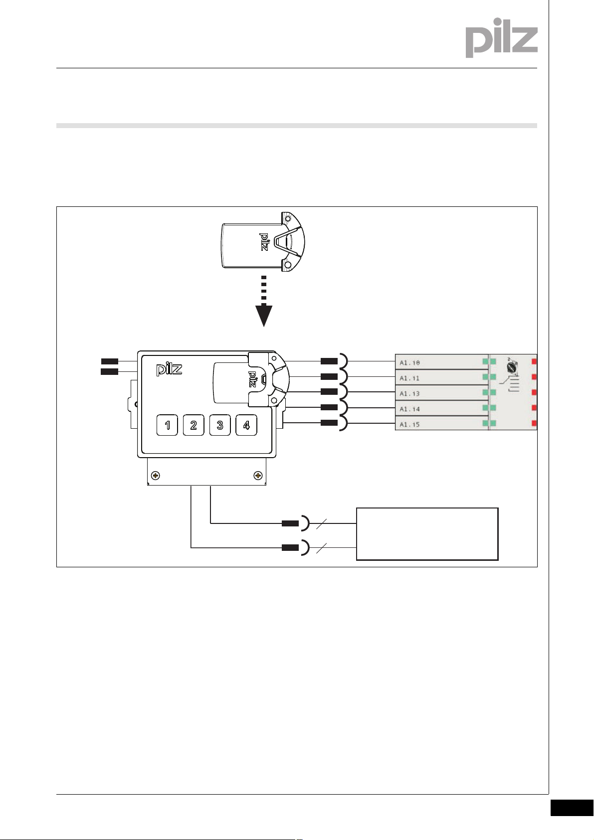
6.3 Connection to PNOZmulti (example: PNOZ m1p)
6.3Connection to PNOZmulti ( example: PNOZ m1p)6300Connection to PNOZmult i (example: PNOZ m1p )6-Verbindung PNOZ m1p BAWS
Pilz GmbH & Co. KG, Felix-Wankel-Straße 2, 73760 Ostfildern, Germany
Telephone: +49 711 3409-0, Telefax: +49 711 3409-133, E-Mail: pilz.gmbh@pilz.de
6-3
Page 28

6 Wiring
6-4
Pilz GmbH & Co. KG, Felix-Wankel-Straße 2, 73760 Ostfildern, Germany
Telephone: +49 711 3409-0, Telefax: +49 711 3409-133, E-Mail: pilz.gmbh@pilz.de
Page 29

7 Operation
77000OperationOperation7-Betrieb allgemein BAWS
CAUTION!
The operating mode selector switch PIT m3.1p may only be
used in conjunction with the actuator and a safety control system. The safety control system must enable safe "1 from n"
evaluation of the semiconductor outputs (OM1 ... OM5) on the
operating mode selector switch.
CAUTION!
If an error occurs, the unit will not change operating modes at
the semiconductor outputs (OM1 ... OM5).
INFORMATION
When voltage is reapplied, operating mode OM1 is automatically
selected, even when no actuator is connected or the actuator is
not recognised correctly.
Pilz GmbH & Co. KG, Felix-Wankel-Straße 2, 73760 Ostfildern, Germany
Telephone: +49 711 3409-0, Telefax: +49 711 3409-133, E-Mail: pilz.gmbh@pilz.de
7-1
Page 30

7 Operation
7.1 Select operating mode
7.1Select operating mode7100Select operating mode7-BA u mschalten BAW S
An operating mode can only be selected if the corresponding actuator
is recognised.
Once an operating mode is selected, the corresponding semiconductor
output OM1 ... OM4 and special service mode (OM5) are activated.
The selected operating mode is displayed via the back-lit button and is
dual-channel monitored via a safety control system.
You can switch between the individual operating modes OM1, OM2,
OM3 and OM4 as required.
7-2
Pilz GmbH & Co. KG, Felix-Wankel-Straße 2, 73760 Ostfildern, Germany
Telephone: +49 711 3409-0, Telefax: +49 711 3409-133, E-Mail: pilz.gmbh@pilz.de
Page 31

7 Operation
t1 t1
OM5
OM1
OM2
OM3
OM4
7.2 Time monitoring
7.2Time monitoring7200Time monitoring7-Zeitüberwachung BAWS
A change of operating modes is only detected once a button has been
operated for a certain time period.
Operating time:
OM1, OM2, OM3, OM4: > 50 ms and < 5 s
Special mode (service) OM5: > 5 s and < 10 s
When a button is released, the semiconductor outputs will switch once
the switchover delay t1 has elapsed (see Technical details).
When changing operating modes, the PIT m3.1p initiates a defined
pause of 50 ms to guarantee that the operating modes do not overlap.
To select an operating mode, follow the instructions below:
Select an operating mode by pressing one of the four buttons. The actuator must be connected to the operating mode selector switch for the
whole time the button is operated; it can be removed afterwards.
Pilz GmbH & Co. KG, Felix-Wankel-Straße 2, 73760 Ostfildern, Germany
Telephone: +49 711 3409-0, Telefax: +49 711 3409-133, E-Mail: pilz.gmbh@pilz.de
7-3
Page 32

7 Operation
7.3 Select special mode (service)
7.3Select special mode (service)7300Select special mode (service)7-Sonderbetriebsart BAWS
Special mode (service) OM5 can be selected from any of the operating
modes OM1 ... OM4, provided the relevant authorisation has been recognised via the "Key Mode Service" actuator.
Proceed as follows:
Slide the “Key Mode Service” actuator on to the bracket of the oper-
ating mode selector switch.
INFORMATION
The actuator must be connected to the operating mode selector
switch for the whole duration of special mode (service).
INFORMATION
Press button 1 and keep it held down for a minimum 5 s/maximum 10 s.
INFORMATION
All four buttons will flash during special mode (service).
If you remove the actuator while the machine is in special service mode
(OM5), the machine's operating mode will automatically switch to OM1.
7-4
Pilz GmbH & Co. KG, Felix-Wankel-Straße 2, 73760 Ostfildern, Germany
Telephone: +49 711 3409-0, Telefax: +49 711 3409-133, E-Mail: pilz.gmbh@pilz.de
Page 33

7 Operation
7.4 Evaluation through safety system
7.4Evaluation through safety system7400Evaluation through safety system7-Auswertung durch Steuerung BAWS
Evaluation must take place via a safe function block, which meets the
following requirements:
The function block must enable safe "1 from n" evaluation of the sem-
iconductor outputs (OM1 ... OM5) on the operating mode selector
switch.
If two or more operating modes are present at the same time, this
must be detected as an error.
The function block must bridge the t1 switchover delay.
Bridging of the switchover pause should not last longer than one sec-
ond.
Pilz GmbH & Co. KG, Felix-Wankel-Straße 2, 73760 Ostfildern, Germany
Telephone: +49 711 3409-0, Telefax: +49 711 3409-133, E-Mail: pilz.gmbh@pilz.de
7-5
Page 34

7 Operation
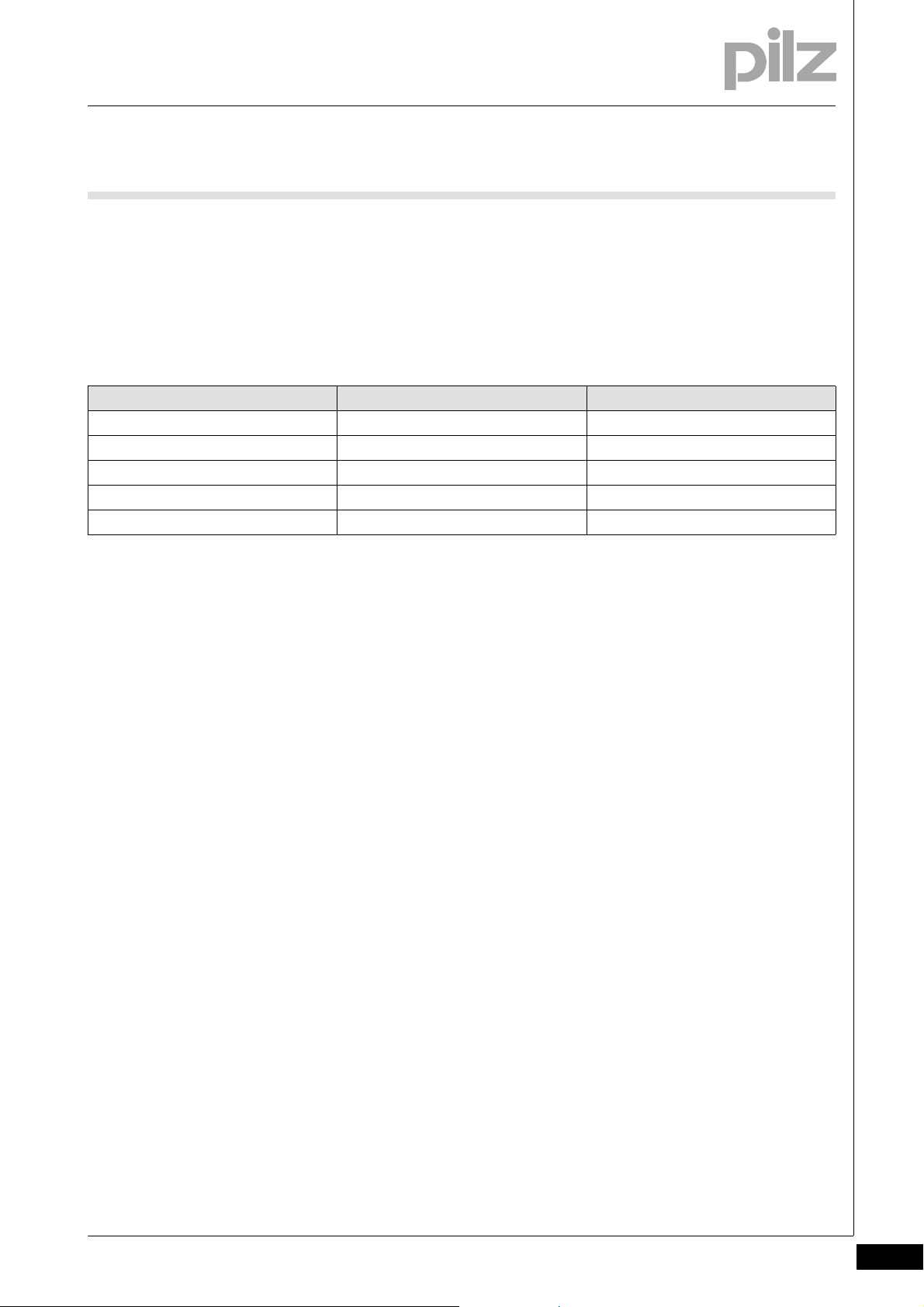
7.5 Troubleshooting
7.5Troubleshooting7500Troubleshooting7-Fehlerbehebu ng BAWS
If an error occurs on the operating mode selector switch, the last operating mode to be set will be retained.
Error Possible cause Remedy
Unable to switch the operating mode Multiple operation of buttons Make sure that only one button is op-
erated.
... Operating time too long or too short Make sure that the period of operation
is observed.
... Actuator is not detected Make sure that the actuator is con-
nected to the operating mode selector
switch correctly.
... No valid authorisation Make sure that the relevant actuator is
used.
7-6
Pilz GmbH & Co. KG, Felix-Wankel-Straße 2, 73760 Ostfildern, Germany
Telephone: +49 711 3409-0, Telefax: +49 711 3409-133, E-Mail: pilz.gmbh@pilz.de
Page 35

7 Operation
7.6 Diagnostics
7.6Diagnostics7600Diag nostics7-Diagnose BAWS
For monitoring and diagnostics of the operating mode selector switch
4 back-lit buttons and 4 signal outputs are available. The outputs report
status information, which is divided into the following information classes:
Selected operating mode
Set authorisation
Messages (e.g. user error and fault)
The status information can be evaluated through a control system.
The back-lit buttons indicate the operating mode selected on the operating mode selector switch.
7.6.1 Signal outputs for status information
Signal outputs for status information7-Meldeausgänge Statusinform ation BAWS
The status information indicates the actions performed by the operator.
These actions are: actuator connected, actuator removed and operating
mode selected.
NOTICE
If OM is selected (SI3:0=8h ... Bh) information remains active
indefinitely. All other information stays active for just 200 ms.
After that time the selected operating mode is again displayed.
Status information SI 3 (MSB) SI 2 SI 1 SI 0 (LSB) SI3:0= [hex]
Reserve 0 0 0 0 0h
Reserve 0 0 0 1 1h
Reserve 0 0 1 0 2h
Reserve 0 0 1 1 3h
Key Mode 1 - connected 0 1 0 0 4h
Key Mode 2 - connected 0 1 0 1 5h
Key Mode 3 - connected 0 1 1 0 6h
Key Mode 4 - connected 0 1 1 1 7h
OM1 selected 1 0 0 0 8h
OM2 selected 1 0 0 1 9h
OM3 selected 1 0 1 0 Ah
OM4 selected 1 0 1 1 Bh
No authorisation 1 1 0 0 Ch
Pilz GmbH & Co. KG, Felix-Wankel-Straße 2, 73760 Ostfildern, Germany
Telephone: +49 711 3409-0, Telefax: +49 711 3409-133, E-Mail: pilz.gmbh@pilz.de
7-7
Page 36

7 Operation
7.6 Diagnostics
Status information SI 3 (MSB) SI 2 SI 1 SI 0 (LSB) SI3:0= [hex]
Device error 1 1 0 1 Dh
Button operated incorrectly 1 1 1 0 Eh
Actuator removed 1 1 1 1 Fh
7-8
Pilz GmbH & Co. KG, Felix-Wankel-Straße 2, 73760 Ostfildern, Germany
Telephone: +49 711 3409-0, Telefax: +49 711 3409-133, E-Mail: pilz.gmbh@pilz.de
Page 37

8 Technical details
8.1 Technical details
81000Technical detailsTechnical details8-8.1Technical details1100Technical details8-][Technische Daten BAWS
Technical details
Sensor's mode of operation Transponder
Typ. operating distance 5.0 mm
Electrical data
Supply voltage UB DC 24 V
Voltage tolerance -15 %/+10 %
Residual ripple DC 20 %
Power consumption at U
Times
Switch-on delay after applying U
Supply interruption before de-energisation 20 ms
Switchover delay t1 50 ms
Operating time of button 1 ... 4 50 ms ... 5 s
Operating time of Service button 5 s ... 10 s
Outputs operating modes
Number of positive-switching single-pole semiconductor
outputs
Switching current per output 20 mA/24 V
Short circuit-proof yes
Residual current at "0" 0.3 mA
Signal level at "1" UB - 3.5 V DC at 20 mA
Status display LED
Signal outputs
Number 8
Switching current per output 20 mA/24 V
Short circuit-proof yes
Residual current at "0" 0.3 mA
Signal level at "1" UB - 3.5 V DC at 20 mA
Inputs
Number 2
Voltage and current at Input circuit DC: 24 V DC 1.5 mA
Galvanic isolation no
Signal level at "0" -3 - +5 V DC
Signal level at "1" 15 - 30 V DC
Safety-related characteristic data
PL in accordance with EN ISO 13849-1: 2006 PL d (Cat. 3)
Category in accordance with EN 954-1 Cat. 3
SIL CL in accordance with EN IEC 62061 SIL CL 2
PFH in accordance with EN IEC 62061 5.75E-09
SIL in accordance with IEC 61511 SIL 2
PFD in accordance with IEC 61511 3.19E-04
T
[year] in accordance with EN ISO 13849-1: 2006 20
M
Environmental data
Vibration to EN 60068-2-6
Frequency 10 - 55 Hz
Amplitude 0.35 mm
EMC EN 60947-5-1
Climatic suitability DIN IEC 60068-2-3
Airgap creepage in accordance with EN 60664-1
Overvoltage category II
Pollution degree 2
Rated insulation voltage 60 V
B
B
2.5 W
1.0 s
5
Pilz GmbH & Co. KG, Felix-Wankel-Straße 2, 73760 Ostfildern, Germany
Telephone: +49 711 3409-0, Telefax: +49 711 3409-133, E-Mail: pilz.gmbh@pilz.de
8-1
Page 38

8 Technical details
8.1 Technical details
Environmental data
Rated impulse withstand voltage 0.80 kV
Ambient temperature -10 - 55 °C
Storage temperature -40 - 85 °C
Climatic suitability in accordance with EN 60068-2-78 95 % r. F. at 40 °C
Mechanical data
Protection type
Mounting (e.g. cabinet) IP54
Housing IP20
Terminals IP20
Torque setting for the fixing screws 0.30 Nm
Housing material
Front ABS
Housing ST + 10µ Zn
Maximum cable runs 30 m
Cross section of external conductors with spring-loaded
terminals: Flexible with/without crimp connectors
Spring-loaded terminals: Terminal points per connection 1
Stripping length 9 mm
Weight 210 g
0.20 - 2.50 mm² , 24 - 12 AWG
Technische Daten_Satz No rmen
The standards current on 2010-02 apply.
8-2
Pilz GmbH & Co. KG, Felix-Wankel-Straße 2, 73760 Ostfildern, Germany
Telephone: +49 711 3409-0, Telefax: +49 711 3409-133, E-Mail: pilz.gmbh@pilz.de
Page 39

8 Technical details
8.2 Order reference
8.2Order reference8200Order reference8-Bestelldaten
Order reference
Type Features Order No.
PIT m3.1p Operating mode selector switches 402 220
Order reference: Accessories
Type Features Order No.
Spring-loaded terminals 1 set 402 301
PIT m3p key mode 1 Actuator Key Mode 01 402 211
PIT m3p key mode 2 Actuator Key Mode 02 402 212
PIT m3p key mode 3 Actuator Key Mode 03 402 213
PIT m3p key mode 4 Actuator Key Mode 04 402 214
PIT m3p key service Actuator Key Mode Service 402 215
Pilz GmbH & Co. KG, Felix-Wankel-Straße 2, 73760 Ostfildern, Germany
Telephone: +49 711 3409-0, Telefax: +49 711 3409-133, E-Mail: pilz.gmbh@pilz.de
8-3
Page 40

8 Technical details
8.2 Order reference
8-4
Pilz GmbH & Co. KG, Felix-Wankel-Straße 2, 73760 Ostfildern, Germany
Telephone: +49 711 3409-0, Telefax: +49 711 3409-133, E-Mail: pilz.gmbh@pilz.de
Page 41

...
1002259-EN-02, 2012-03 Printed in Germany
© Pilz GmbH & Co. KG, 2011
+49 711 3409-444
support@pilz.com
Pilz GmbH & Co. KG
Felix-Wankel-Straße 2
73760 Ostfildern, Germany
Telephone: +49 711 3409-0
Telefax: +49 711 3409-133
E-Mail: pilz.gmbh@pilz.de
Internet: www.pilz.com
Technical support
In many countries we are
represented by our subsidiaries
and sales partners.
Please refer to our homepage
for further details or contact our
headquarters.
InduraNET p
®
, Pilz
®
, PIT
®
, PMCprotego
®
, PMI
®
, PNOZ
®
, Primo
®
, PSEN
®
, PSS
®
, PVIS
®
, SafetyBUS p
®
, SafetyEYE
®
, SafetyNET p
®
, the spirit of safety
®
are registered and protected trademarks
of Pilz GmbH & Co. KG in some countries. We would point out that product features may vary from the details stated in this document, depending on the status at the time of publication and the scope
of the equipment. We accept no responsibility for the validity, accuracy and entirety of the text and graphics presented in this information. Please contact our Technical Support if you have any questions.
Contact address
 Loading...